CN113877269B - Sewage filtering device - Google Patents
Sewage filtering device Download PDFInfo
- Publication number
- CN113877269B CN113877269B CN202111278946.0A CN202111278946A CN113877269B CN 113877269 B CN113877269 B CN 113877269B CN 202111278946 A CN202111278946 A CN 202111278946A CN 113877269 B CN113877269 B CN 113877269B
- Authority
- CN
- China
- Prior art keywords
- sewage
- backflushing
- shell
- sleeve
- filter screen
- Prior art date
- Legal status (The legal status is an assumption and is not a legal conclusion. Google has not performed a legal analysis and makes no representation as to the accuracy of the status listed.)
- Active
Links
- 239000010865 sewage Substances 0.000 title claims abstract description 86
- 238000001914 filtration Methods 0.000 title claims abstract description 22
- XLYOFNOQVPJJNP-UHFFFAOYSA-N water Chemical compound O XLYOFNOQVPJJNP-UHFFFAOYSA-N 0.000 claims abstract description 67
- 239000008213 purified water Substances 0.000 claims abstract description 28
- 239000007788 liquid Substances 0.000 claims description 14
- 238000011010 flushing procedure Methods 0.000 claims description 10
- 239000008188 pellet Substances 0.000 claims description 4
- 238000007789 sealing Methods 0.000 claims description 4
- 239000002184 metal Substances 0.000 claims description 3
- 239000002351 wastewater Substances 0.000 claims 1
- 239000012535 impurity Substances 0.000 description 8
- 238000000034 method Methods 0.000 description 5
- 238000009825 accumulation Methods 0.000 description 2
- 230000000694 effects Effects 0.000 description 2
- 230000035699 permeability Effects 0.000 description 2
- 230000006835 compression Effects 0.000 description 1
- 238000007906 compression Methods 0.000 description 1
- 238000000151 deposition Methods 0.000 description 1
- 238000007599 discharging Methods 0.000 description 1
- 230000005484 gravity Effects 0.000 description 1
Images


Classifications
-
- B—PERFORMING OPERATIONS; TRANSPORTING
- B01—PHYSICAL OR CHEMICAL PROCESSES OR APPARATUS IN GENERAL
- B01D—SEPARATION
- B01D29/00—Filters with filtering elements stationary during filtration, e.g. pressure or suction filters, not covered by groups B01D24/00 - B01D27/00; Filtering elements therefor
- B01D29/01—Filters with filtering elements stationary during filtration, e.g. pressure or suction filters, not covered by groups B01D24/00 - B01D27/00; Filtering elements therefor with flat filtering elements
- B01D29/03—Filters with filtering elements stationary during filtration, e.g. pressure or suction filters, not covered by groups B01D24/00 - B01D27/00; Filtering elements therefor with flat filtering elements self-supporting
-
- B—PERFORMING OPERATIONS; TRANSPORTING
- B01—PHYSICAL OR CHEMICAL PROCESSES OR APPARATUS IN GENERAL
- B01D—SEPARATION
- B01D29/00—Filters with filtering elements stationary during filtration, e.g. pressure or suction filters, not covered by groups B01D24/00 - B01D27/00; Filtering elements therefor
- B01D29/50—Filters with filtering elements stationary during filtration, e.g. pressure or suction filters, not covered by groups B01D24/00 - B01D27/00; Filtering elements therefor with multiple filtering elements, characterised by their mutual disposition
- B01D29/56—Filters with filtering elements stationary during filtration, e.g. pressure or suction filters, not covered by groups B01D24/00 - B01D27/00; Filtering elements therefor with multiple filtering elements, characterised by their mutual disposition in series connection
-
- B—PERFORMING OPERATIONS; TRANSPORTING
- B01—PHYSICAL OR CHEMICAL PROCESSES OR APPARATUS IN GENERAL
- B01D—SEPARATION
- B01D29/00—Filters with filtering elements stationary during filtration, e.g. pressure or suction filters, not covered by groups B01D24/00 - B01D27/00; Filtering elements therefor
- B01D29/62—Regenerating the filter material in the filter
- B01D29/66—Regenerating the filter material in the filter by flushing, e.g. counter-current air-bumps
- B01D29/68—Regenerating the filter material in the filter by flushing, e.g. counter-current air-bumps with backwash arms, shoes or nozzles
Landscapes
- Chemical & Material Sciences (AREA)
- Chemical Kinetics & Catalysis (AREA)
- Sewage (AREA)
- Filtration Of Liquid (AREA)
Abstract
The invention relates to a sewage filtering device, which effectively solves the problem of blockage of a sewage filtering filter screen; the technical scheme includes that the sewage treatment device comprises a sewage tank, a purified water tank and a cylindrical shell, wherein a sewage inlet is formed in the left end of the shell, a purified water outlet is formed in the side wall of the shell, and the purified water outlet is spaced from the right end of the shell; a filter assembly is arranged in the shell, a backflushing sewage draining outlet is formed in the right end face of the shell, a backflow pipe is connected to the outer end of the backflushing sewage draining outlet and communicated with the sewage tank, the backflushing sewage draining outlet is opened to backflush the filter screen after the filter assembly crosses the clean water outlet, and the backflushing water flows back into the sewage tank to be filtered again; the invention backflushs the filter screen after each filtration cycle, so that the filter screen can be kept permeable all the time.
Description
Technical Field
The invention relates to the field of sewage treatment, in particular to a sewage filtering device.
Background
When sewage is filtered, impurities can be deposited on the filter screen to block the filter screen, and the filter screen is generally subjected to back flushing dredging at regular intervals at present; however, impurities can form stubborn concretion after being deposited on the filter screen for a long time, the impurities are difficult to wash away during back flushing, and before back flushing, the permeability of the filter screen is gradually reduced along with the accumulation of the impurities, the flow is reduced, and the filtering efficiency is reduced; some equipment can be provided with two groups of filtering units for switching, so that non-stop backflushing is realized, but the equipment volume is increased undoubtedly, only one filtering unit is in a working state, and the utilization rate is low; furthermore, when the existing backflushing equipment performs backflushing, the backflushing flow at each position of the filter screen is uneven, backflushing water can preferentially pass through an area with good permeability, the flow of an area with serious blockage is smaller, and backflushing and boosting are difficult.
Disclosure of Invention
The invention provides a sewage filtering device, aiming at solving the problem of blockage of a sewage filtering filter screen.
The technical scheme for solving the problem is that the sewage filtering device comprises a sewage tank, a purified water tank and a cylindrical shell, wherein the left end of the shell is provided with a sewage inlet connected with the sewage tank, the sewage inlet is provided with a water inlet one-way valve, the side wall of the shell is provided with a purified water outlet connected with the purified water tank, the purified water outlet is provided with a water outlet one-way valve, and the purified water outlet is close to the right end of the shell and is spaced from the right end of the shell; a sleeve which is attached to the inner wall of the shell and can reciprocate left and right is arranged in the shell, a filter screen and a piston positioned on the left side of the filter screen are arranged in the sleeve, a liquid passing hole is formed in the piston, a liquid passing one-way valve which enables water to flow through the liquid passing hole from left to right is arranged in the liquid passing hole, and a spring is arranged on the left side of the piston; a backflushing sewage discharge channel is formed in the side wall of the sleeve, one end of the backflushing sewage discharge channel is located on the right end face of the sleeve, and the other end of the backflushing sewage discharge channel is located on the left side of the filter screen; a backflushing sewage discharge port is formed in the right end face of the shell, a backflow pipe is connected to the outer end of the backflushing sewage discharge port and communicated with the sewage tank, and backflushing water flows into the sewage tank to be filtered again; an internal threaded pipe is rotatably installed on the right end face of the shell, a through hole is formed in the side wall of the internal threaded pipe, an external threaded pipe is installed at one end, located on the end face of the sleeve, of the backflushing sewage discharge channel, after the right end of the sleeve crosses the purified water outlet, the external threaded pipe can be inserted into the internal threaded pipe, and the external threaded pipe can drive the internal threaded pipe to rotate along with the sleeve to move rightwards continuously.
The left end of the sleeve is fixedly provided with a push rod which extends out of the shell to the left, the left side of the shell is provided with a rotary table, a short rod which is vertical to the disc surface is fixed at the non-circle center position of the disc surface of the rotary table, the left end of the push rod is fixedly provided with a sliding groove which is vertical to the push rod, and the short rod is arranged in the sliding groove.
And sealing rings are arranged on the outer wall of the sleeve and at the positions where the push rod at the left end of the shell penetrates.
The return pipe is vertically arranged at one section of the right end of the shell, and the lower end of the return pipe is provided with an openable end cover through threads.
The backflow pipe is internally provided with a small ball, the inner wall of the backflow pipe is provided with a limiting block, the small ball falls on the limiting block when no water flows in the backflow pipe, and the connecting position of the backflushing sewage discharge outlet and the backflow pipe is positioned between the limiting block and the end cover.
The diameter of the small ball is 2 to 4 mm smaller than the inner diameter of the return pipe.
The density of the pellets is between 1.1 and 1.3.
The small ball is in the form of a hollow metal ball, a threaded hole communicated with the inner cavity of the small ball is formed in the small ball, and the through hole is sealed by a screw.
The right end of the external thread pipe is provided with a rubber valve which is closed when the recoil pressure is not available and is opened under the action of the counter-pressure force when the recoil pressure is available.
The left and right sides of filter screen all install the support frame.
The invention carries out backflushing on the filter screen after each filtering cycle, can lead the filter screen to be always transparent, and has a pressure boosting and force storing process before backflushing, thus leading the pressure at all positions of the filter screen to be evenly distributed and improving the backflushing pressure difference.
Drawings
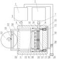
Figure 1 is a front cross-sectional view of the present invention with the sleeve at the far left end.
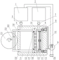
Fig. 2 is a front sectional view of the invention when the cartridge is moved to close the clean water outlet.
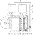
FIG. 3 is a front cross-sectional view of the present invention after completion of the pressure increasing power accumulation on the right side of the piston.
FIG. 4 is a front cross-sectional view of the invention with the sleeve moved to the far right end and the recoil completed.
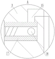
Fig. 5 is an enlarged view of the position a in fig. 1.
Fig. 6 is an enlarged view of the position B in fig. 3.
Fig. 7 is an enlarged view of the position C in fig. 4.
Fig. 8 is an enlarged view of the position D in fig. 3.
Fig. 9 is an end view of the support bracket.
Detailed Description
The following detailed description of specific embodiments of the invention refers to the accompanying drawings.
The invention comprises a sewage tank 1, a purified water tank 2 and a cylindrical shell 3, wherein the left end of the shell 3 is provided with a sewage inlet 4 connected with the sewage tank 1, the sewage inlet 4 is provided with a water inlet one-way valve 5, the side wall of the shell 3 is provided with a purified water outlet 6 connected with the purified water tank 2, the purified water outlet 6 is provided with a water outlet one-way valve 7, and the purified water outlet 6 is close to the right end of the shell 3 and is spaced from the right end of the shell 3; a sleeve 8 which is attached to the inner wall of the shell 3 and can move left and right in a reciprocating manner is arranged in the shell 3, a filter screen 9 and a piston 10 which is positioned on the left side of the filter screen 9 are arranged in the sleeve 8, a liquid passing hole 11 is formed in the piston 10, a liquid passing one-way valve which enables water to flow through the liquid passing hole 11 from left to right is arranged in the liquid passing hole 11, and a spring 13 is arranged on the left side of the piston 10; when the sleeve 8 moves leftwards, sewage on the left side of the piston 10 is pressed into the right side of the filter screen 9 through the liquid hole 11 and the filter screen 9, when the shell 3 moves rightwards, the piston 10 discharges purified water on the right side of the piston from the purified water outlet 6, meanwhile, the left side of the piston 10 sucks the sewage, and the sleeve 8 reciprocates to realize continuous filtering operation; a backflushing sewage discharge channel 14 is formed in the side wall of the sleeve 8, one end of the backflushing sewage discharge channel 14 is located on the right end face of the sleeve 8, the other end of the backflushing sewage discharge channel 14 is located on the left side of the filter screen 9, when the sleeve 8 moves on the left side of the purified water outlet 6, no matter the sleeve moves leftwards or rightwards, under the action of the right elastic force of the spring 13, the piston 10 is located at the rightmost position, the port, located on the left side of the filter screen 9, of the backflushing sewage discharge channel 14 is closed, when the sleeve 8 moves rightwards to close the purified water outlet 6, water on the right side of the piston 10 cannot be discharged any more when the sleeve 8 moves rightwards continuously, water pressure will rise, the piston 10 is pushed leftwards gradually, finally the port, located on the left side of the backflushing sewage discharge channel 14 is opened, and at the sleeve 8 continues to move rightwards to be switched into a backflushing sewage discharge passage; a backflushing sewage discharge outlet 15 is formed in the right end face of the shell 3, a backflow pipe 16 is connected to the outer end of the backflushing sewage discharge outlet 15, the backflow pipe 16 is communicated with the sewage tank 1, and backflushing water flows back into the sewage tank 1 for secondary filtration; an internal threaded pipe 17 is rotatably installed on the right end face of the shell 3, a through hole 18 is formed in the side wall of the internal threaded pipe 17, an external threaded pipe 19 is installed at one end, located on the end face of the sleeve 8, of the backflushing sewage discharge channel 14, after the right end of the sleeve 8 passes over the purified water outlet 6, the external threaded pipe 19 can be inserted into the internal threaded pipe 17, and the external threaded pipe 19 can drive the internal threaded pipe 17 to rotate as the sleeve 8 continues to move rightwards; when the external thread pipe 19 is not inserted into the internal thread pipe 17, the through hole 18 on the internal thread pipe 17 is staggered with the backflushing sewage discharge outlet 15, after the external thread pipe 19 is inserted into the internal thread pipe 17 and drives the internal thread pipe 17 to rotate for a certain angle, the through hole 18 on the internal thread pipe 17 rotates to be communicated with the backflushing sewage discharge outlet 15, and the rotation angle is more than or equal to 90 degrees and less than or equal to 180 degrees.
The left end of the sleeve 8 is fixedly provided with a push rod 20 extending out of the shell 3 to the left, the left side of the shell 3 is provided with a rotary table 21, a short rod 22 vertical to the disc surface is fixed at the non-circle center position of the disc surface of the rotary table 21, the left end of the push rod 20 is fixedly provided with a sliding groove 23 vertical to the push rod 20, the short rod 22 is arranged in the sliding groove 23, and when the rotary table 21 rotates, the push rod 20 and the sleeve 8 are pulled to reciprocate left and right through the short rod 22 and the sliding groove 23.
And sealing rings 24 are respectively arranged on the outer wall of the sleeve 8 and the position where the push rod 20 at the left end of the shell 3 penetrates, so that the sealing performance of the sliding fit position is ensured.
The return pipe 16 is vertically arranged at a section of the right end of the shell 3, an openable end cover 25 is installed at the lower end of the return pipe 16 through threads, and impurities deposited in the return pipe 16 can be discharged by opening the end cover 25.
A small ball 26 is arranged in the return pipe 16, a limiting block 27 is arranged on the inner wall of the return pipe 16, the small ball 26 falls on the limiting block 27 when no water flow exists in the return pipe 16, and the connecting position of the backflushing sewage discharge port 15 and the return pipe 16 is positioned between the limiting block 27 and the end cover 25; during backflushing, the small ball 26 is pushed by the backflushing water to move upwards, the water on the upper side of the small ball 26 is discharged into the sewage tank 1, when the backflushing is finished, the small ball 26 slowly descends, meanwhile, impurities in the backflushing water below the small ball 26 settle at the bottom of the backflow pipe 16, after the small ball 26 falls to the bottom, the water which is primarily settled is above the small ball 26, and during the next backflushing, the small ball 26 can prevent the non-settled backflushing water and the backflushing water which is settled by the upper wheel from being mixed in a large amount, so that the impurities are prevented from being flushed back into the sewage tank 1 in a large amount.
The diameter of the small ball 26 is 2 to 4 mm smaller than the inner diameter of the return pipe 16, so that the small ball 26 can float up and down freely in the return pipe 16, and the water on the upper side and the lower side of the small ball 26 can be effectively prevented from being mixed greatly.
The density of the small balls 26 is between 1.1 and 1.3, namely, the density is slightly larger than that of water, so that the small balls 26 slowly sink after the back flushing is finished, and sufficient settling time is provided for the back flushing water on the lower side.
The small ball 26 is in the form of a hollow metal ball, a threaded hole communicated with the inner cavity of the small ball 26 is formed in the small ball 26, the threaded hole is blocked by a screw, and water can be added into the inner cavity of the small ball 26 by unscrewing the screw, so that the specific gravity of the small ball 26 is adjusted, and the falling speed of the small ball is controlled.
The right end of the external thread tube 19 is provided with a rubber valve 28, the rubber valve 28 is closed when the recoil pressure is not available, and the rubber valve 28 is opened under the action of the recoil pressure when the recoil pressure is available; the rubber diaphragm 28 is closed after the external thread pipe 19 is pulled out from the internal thread pipe 17, so that the back flushing water remained in the back flushing sewage discharging channel 14 can be prevented from entering the right side of the filter screen 9.
The left side and the right side of the filter screen 9 are both provided with a support frame 29, so that the rigidity of the filter screen 9 is kept.
The specific working process of the invention is as follows:
starting the rotary table 21, wherein the rotary table 21 pulls the sleeve 8 to reciprocate left and right through the push rod 20, when the sleeve 8 moves rightwards, the left side of the piston 10 sucks sewage from the sewage tank 1, when the sleeve 8 moves leftwards, the sewage on the left side is pressed to the right side through the liquid hole 11 and the filter screen 9 to be filtered, and when the piston 10 moves rightwards again, the clean water on the right side is discharged through the clean water outlet 6; when the sleeve 8 moves on the left side of the purified water outlet 6, no matter the sleeve moves leftwards or rightwards, under the action of the right elasticity of the spring 13, the piston 10 is positioned at the rightmost position to seal the port of the backflushing sewage channel 14 on the left side of the filter screen 9.
When the sleeve 8 moves rightwards to seal the purified water outlet 6, if the sleeve continues to move rightwards, water on the right side of the piston 10 cannot be discharged any more, the water pressure will rise, the piston 10 is gradually pushed leftwards, and finally the port of the backflushing sewage discharge channel 14 on the left side of the filter screen 9 is opened; when the sleeve 8 seals the purified water outlet 6, the external threaded pipe 19 is inserted into the internal threaded pipe 17, the sleeve 8 continuously moves rightwards, the external threaded pipe 19 drives the internal threaded pipe 17 to rotate until the through hole 18 on the internal threaded pipe 17 is communicated with the backflushing sewage discharge port 15, and the thread sections on the external threaded pipe 19 and the internal threaded pipe 17 are engaged; the piston 10 moves leftwards relative to the sleeve 8 and the internal threaded pipe 17 rotates simultaneously, when the left port of the backflushing discharge channel is opened and the through hole 18 in the internal threaded pipe 17 is communicated with the backflushing sewage discharge port 15, the backflushing sewage discharge channel is communicated, and the sleeve 8 moves rightwards continuously, so that water on the right side of the filter screen 9 backflushing the filter screen 9 leftwards and then is discharged into the return pipe 16 from the backflushing sewage discharge channel 14 and the backflushing sewage discharge port 15.
In the process, when the piston 10 moves left relative to the sleeve 8, the spring 13 is compressed, the water pressure on the right side of the piston 10 is increased, the pressure of each part of the filter screen 9 is uniformly increased to a high value, which is equivalent to a boosting and force accumulating process, when the backflushing sewage discharge passage is opened, the pressure on the left side of the filter screen 9 is reduced, so that the backflushing is always maintained at a high pressure difference, and the backflushing effect is ensured.
The sleeve 8 moves to the rightmost end and then returns back to move leftwards, the piston 10 moves back to the right under the action of the spring 13 to close the port of the backflushing sewage discharge passage 14, the external threaded pipe 19 is pulled out of the internal threaded pipe 17, the internal threaded pipe 17 rotates reversely to reset, and the backflushing sewage discharge port 15 is closed.
In the end section of each filtration and drainage, the piston 10 and the threaded pipe are switched into a backflushing passage, a small part of clean water is used for backflushing the filter screen 9, so that impurities can be prevented from depositing on the filter screen 9 for a long time to form stubborn concretions, the filter screen 9 can be kept through all the time, and the filtration efficiency is improved; in addition, before backflushing, through the leftward movement of the piston 10 and the compression of the spring 13, a pressure boosting and force storing process is arranged on the right side of the piston 10, after a sewage discharge channel on the left side of the filter screen 9 is communicated, a high backflushing pressure difference is formed on two sides of the filter screen 9, pressure at all positions of the filter screen 9 is uniformly distributed, the problem that the pressure and flow at the position where the filter screen 9 is blocked are difficult to rise is avoided, and the backflushing effect is improved.
Claims (7)
1. A sewage filtering device comprises a sewage tank (1), a purified water tank (2) and a cylindrical shell (3), and is characterized in that a sewage inlet (4) connected with the sewage tank (1) is arranged at the left end of the shell (3), a water inlet one-way valve (5) is arranged on the sewage inlet (4), a purified water outlet (6) connected with the purified water tank (2) is arranged on the side wall of the shell (3), a water outlet one-way valve (7) is arranged on the purified water outlet (6), and the purified water outlet (6) is close to the right end of the shell (3) and is away from the right end of the shell (3); a sleeve (8) which is attached to the inner wall of the shell (3) and can move left and right in a reciprocating manner is arranged in the shell (3), a filter screen (9) and a piston (10) which is positioned on the left side of the filter screen (9) are arranged in the sleeve (8), a liquid passing hole (11) is formed in the piston (10), a liquid passing one-way valve which enables water to flow through the liquid passing hole (11) from left to right is arranged in the liquid passing hole (11), and a spring (13) is arranged on the left side of the piston (10); a backflushing sewage discharge channel (14) is formed in the side wall of the sleeve (8), one end of the backflushing sewage discharge channel (14) is located on the right end face of the sleeve (8), and the other end of the backflushing sewage discharge channel is located on the left side of the filter screen (9); a backflushing sewage draining outlet (15) is formed in the right end face of the shell (3), a backflow pipe (16) is connected to the outer end of the backflushing sewage draining outlet (15), the backflow pipe (16) is communicated with the sewage tank (1), and backflushing water flows back into the sewage tank (1) for secondary filtration; an internal threaded pipe (17) is rotatably mounted on the right end face of the shell (3), a through hole (18) is formed in the side wall of the internal threaded pipe (17), an external threaded pipe (19) is mounted at one end, located on the end face of the sleeve (8), of the backflushing sewage discharge channel (14), after the right end of the sleeve (8) passes over the purified water outlet (6), the external threaded pipe (19) is inserted into the internal threaded pipe (17), and the external threaded pipe (19) moves rightwards continuously along with the sleeve (8) to drive the internal threaded pipe (17) to rotate;
a small ball (26) is arranged in the return pipe (16), a limiting block (27) is arranged on the inner wall of the return pipe (16), the small ball (26) falls on the limiting block (27) when no water flows in the return pipe (16), and the connecting position of the backflushing sewage discharge outlet (15) and the return pipe (16) is positioned below the limiting block (27); the diameter of the small balls (26) is 2 to 4 mm smaller than the inner diameter of the return pipe (16), and the density of the small balls (26) is between 1.1 and 1.3.
2. The sewage filtering device according to claim 1, wherein a push rod (20) extending out of the housing (3) to the left is fixed at the left end of the sleeve (8), a rotary table (21) is arranged at the left side of the housing (3), a short rod (22) vertical to the disc surface is fixed at a non-circular center position of the disc surface of the rotary table (21), a sliding groove (23) vertical to the push rod (20) is fixed at the left end of the push rod (20), and the short rod (22) is arranged in the sliding groove (23).
3. The sewage filtering device according to claim 1, wherein the outer wall of the sleeve (8) and the position through which the push rod (20) at the left end of the housing (3) passes are provided with sealing rings (24).
4. A sewage filter unit according to claim 1, characterised in that the return pipe (16) is arranged vertically at the right end of the housing (3), and that the lower end of the return pipe (16) is threaded with an openable end cap (25).
5. A sewage filter unit according to claim 1 characterised in that said pellet (26) is in the form of a hollow metal pellet, the pellet (26) being provided with a threaded hole communicating with its inner cavity, the through hole (18) being closed off by a screw.
6. A device for filtering waste water according to claim 1, wherein the male screw-threaded pipe (19) is provided at its right end with a rubber diaphragm (28), the rubber diaphragm (28) being closed in the absence of a back flushing pressure and being opened by the back flushing pressure during back flushing.
7. A device according to claim 1, characterized in that the left and right sides of the screen (9) are provided with support frames (29).
Priority Applications (1)
| Application Number | Priority Date | Filing Date | Title |
|---|---|---|---|
| CN202111278946.0A CN113877269B (en) | 2021-10-31 | 2021-10-31 | Sewage filtering device |
Applications Claiming Priority (1)
| Application Number | Priority Date | Filing Date | Title |
|---|---|---|---|
| CN202111278946.0A CN113877269B (en) | 2021-10-31 | 2021-10-31 | Sewage filtering device |
Publications (2)
| Publication Number | Publication Date |
|---|---|
| CN113877269A CN113877269A (en) | 2022-01-04 |
| CN113877269B true CN113877269B (en) | 2022-11-11 |
Family
ID=79014569
Family Applications (1)
| Application Number | Title | Priority Date | Filing Date |
|---|---|---|---|
| CN202111278946.0A Active CN113877269B (en) | 2021-10-31 | 2021-10-31 | Sewage filtering device |
Country Status (1)
| Country | Link |
|---|---|
| CN (1) | CN113877269B (en) |
Families Citing this family (2)
| Publication number | Priority date | Publication date | Assignee | Title |
|---|---|---|---|---|
| CN115319146A (en) * | 2022-10-11 | 2022-11-11 | 镇江美杰超硬材料有限公司 | High-precision multi-groove grinding wheel hole machining assembly |
| CN117599502B (en) * | 2024-01-24 | 2024-03-26 | 山西坤杰建设工程有限公司 | Drainage pipeline filtering and impurity removing device |
Citations (6)
| Publication number | Priority date | Publication date | Assignee | Title |
|---|---|---|---|---|
| CN103115451A (en) * | 2013-03-23 | 2013-05-22 | 林辉玉 | Backflow-preventing water feeding indicating device of solar water heater |
| CN205182292U (en) * | 2015-09-06 | 2016-04-27 | 孙银焕 | Utensil backwash function's outdoor water purifier |
| CN210543661U (en) * | 2019-08-02 | 2020-05-19 | 江苏建筑职业技术学院 | Automatic back-flushing filtering device for mine water |
| CN211328402U (en) * | 2019-12-02 | 2020-08-25 | 江西先净者科技有限公司 | Filter belt cleaning device for sewage treatment |
| CN212283067U (en) * | 2020-05-12 | 2021-01-05 | 辽宁科诺环保设备有限公司 | Wisdom water utilities has anti-cleaning function's cities and towns integration sewage treatment device |
| CN212818391U (en) * | 2020-07-06 | 2021-03-30 | 宗雪谊 | Sludge discharge device for sewage treatment |
-
2021
- 2021-10-31 CN CN202111278946.0A patent/CN113877269B/en active Active
Patent Citations (6)
| Publication number | Priority date | Publication date | Assignee | Title |
|---|---|---|---|---|
| CN103115451A (en) * | 2013-03-23 | 2013-05-22 | 林辉玉 | Backflow-preventing water feeding indicating device of solar water heater |
| CN205182292U (en) * | 2015-09-06 | 2016-04-27 | 孙银焕 | Utensil backwash function's outdoor water purifier |
| CN210543661U (en) * | 2019-08-02 | 2020-05-19 | 江苏建筑职业技术学院 | Automatic back-flushing filtering device for mine water |
| CN211328402U (en) * | 2019-12-02 | 2020-08-25 | 江西先净者科技有限公司 | Filter belt cleaning device for sewage treatment |
| CN212283067U (en) * | 2020-05-12 | 2021-01-05 | 辽宁科诺环保设备有限公司 | Wisdom water utilities has anti-cleaning function's cities and towns integration sewage treatment device |
| CN212818391U (en) * | 2020-07-06 | 2021-03-30 | 宗雪谊 | Sludge discharge device for sewage treatment |
Also Published As
| Publication number | Publication date |
|---|---|
| CN113877269A (en) | 2022-01-04 |
Similar Documents
| Publication | Publication Date | Title |
|---|---|---|
| CN113877269B (en) | Sewage filtering device | |
| CN113877267B (en) | Sewage treatment filter screen recoil device | |
| CN109589670B (en) | Automatic net cleaning device for sewage filtration | |
| CN111974042B (en) | Anti-washing unit of sewage pump entry for PTA production | |
| CN112225362B (en) | Integrated water-saving full-house water purifying equipment | |
| CN1843558B (en) | Backwash filter | |
| CN114344974A (en) | Sludge filter press for sewage treatment | |
| CN211097838U (en) | Back flush filter | |
| CN113877268B (en) | Sewage treatment filtering component | |
| CN2875557Y (en) | Back flushing filter | |
| CN115920496A (en) | Booster-type permanent magnet waste liquid is filter screen cleaning machine for recovery processing | |
| CN114307307A (en) | Water purification filter and cleaning auxiliary device for water purification filter | |
| CN208791225U (en) | A kind of nanometer of sea-island fibre composite filtering material | |
| CN110566695A (en) | Check valve control structure for injection pump | |
| CN117028331B (en) | Efficient axial flow pump for sewage treatment equipment | |
| CN219050445U (en) | Self-treatment system for solid waste in polyvinyl chloride filter | |
| CN215275920U (en) | Backflushing cleaning system for filter tank of waterworks | |
| CN113387475B (en) | High-efficient antibacterial purifier | |
| CN220633181U (en) | Filter equipment for municipal administration water supply and drainage | |
| CN220364746U (en) | Water inlet and outlet integrated pipe of washing equipment | |
| CN220110576U (en) | Water conservancy is with pipeline that has filtration | |
| CN109758813B (en) | Water purifier | |
| CN213655779U (en) | Gate valve with purification function | |
| CN216604300U (en) | Bury formula integration sewage treatment device | |
| CN221372308U (en) | Desilting device for construction |
Legal Events
| Date | Code | Title | Description |
|---|---|---|---|
| PB01 | Publication | ||
| PB01 | Publication | ||
| SE01 | Entry into force of request for substantive examination | ||
| SE01 | Entry into force of request for substantive examination | ||
| TA01 | Transfer of patent application right |
Effective date of registration: 20221011 Address after: 704, Floor 7, Building 2, Yard 106, Kexing West Road, Huilongguan Town, Changping District, Beijing 102200 Applicant after: Beijing Oulile Environmental Engineering Co.,Ltd. Address before: 450000 building 3, phase I, headquarters enterprise base, No. 1, Cuizhu street, high tech Zone, Zhengzhou City, Henan Province Applicant before: Gai Mingxiu |
|
| TA01 | Transfer of patent application right | ||
| GR01 | Patent grant | ||
| GR01 | Patent grant |