CN113873902A - Inductively heatable aerosol-forming rod and forming device for producing such rod - Google Patents
Inductively heatable aerosol-forming rod and forming device for producing such rod Download PDFInfo
- Publication number
- CN113873902A CN113873902A CN202080017154.5A CN202080017154A CN113873902A CN 113873902 A CN113873902 A CN 113873902A CN 202080017154 A CN202080017154 A CN 202080017154A CN 113873902 A CN113873902 A CN 113873902A
- Authority
- CN
- China
- Prior art keywords
- aerosol
- forming
- susceptor
- core
- sleeve
- Prior art date
- Legal status (The legal status is an assumption and is not a legal conclusion. Google has not performed a legal analysis and makes no representation as to the accuracy of the status listed.)
- Pending
Links
Images


Classifications
-
- A—HUMAN NECESSITIES
- A24—TOBACCO; CIGARS; CIGARETTES; SIMULATED SMOKING DEVICES; SMOKERS' REQUISITES
- A24C—MACHINES FOR MAKING CIGARS OR CIGARETTES
- A24C5/00—Making cigarettes; Making tipping materials for, or attaching filters or mouthpieces to, cigars or cigarettes
- A24C5/01—Making cigarettes for simulated smoking devices
-
- A—HUMAN NECESSITIES
- A24—TOBACCO; CIGARS; CIGARETTES; SIMULATED SMOKING DEVICES; SMOKERS' REQUISITES
- A24B—MANUFACTURE OR PREPARATION OF TOBACCO FOR SMOKING OR CHEWING; TOBACCO; SNUFF
- A24B15/00—Chemical features or treatment of tobacco; Tobacco substitutes, e.g. in liquid form
- A24B15/10—Chemical features of tobacco products or tobacco substitutes
- A24B15/12—Chemical features of tobacco products or tobacco substitutes of reconstituted tobacco
- A24B15/14—Chemical features of tobacco products or tobacco substitutes of reconstituted tobacco made of tobacco and a binding agent not derived from tobacco
-
- A—HUMAN NECESSITIES
- A24—TOBACCO; CIGARS; CIGARETTES; SIMULATED SMOKING DEVICES; SMOKERS' REQUISITES
- A24B—MANUFACTURE OR PREPARATION OF TOBACCO FOR SMOKING OR CHEWING; TOBACCO; SNUFF
- A24B3/00—Preparing tobacco in the factory
- A24B3/14—Forming reconstituted tobacco products, e.g. wrapper materials, sheets, imitation leaves, rods, cakes; Forms of such products
-
- A—HUMAN NECESSITIES
- A24—TOBACCO; CIGARS; CIGARETTES; SIMULATED SMOKING DEVICES; SMOKERS' REQUISITES
- A24C—MACHINES FOR MAKING CIGARS OR CIGARETTES
- A24C5/00—Making cigarettes; Making tipping materials for, or attaching filters or mouthpieces to, cigars or cigarettes
- A24C5/14—Machines of the continuous-rod type
- A24C5/18—Forming the rod
- A24C5/1807—Forming the rod with compressing means, e.g. garniture
-
- A—HUMAN NECESSITIES
- A24—TOBACCO; CIGARS; CIGARETTES; SIMULATED SMOKING DEVICES; SMOKERS' REQUISITES
- A24C—MACHINES FOR MAKING CIGARS OR CIGARETTES
- A24C5/00—Making cigarettes; Making tipping materials for, or attaching filters or mouthpieces to, cigars or cigarettes
- A24C5/14—Machines of the continuous-rod type
- A24C5/18—Forming the rod
- A24C5/1821—Forming the rod containing different tobacco mixtures, e.g. composite rods
-
- A—HUMAN NECESSITIES
- A24—TOBACCO; CIGARS; CIGARETTES; SIMULATED SMOKING DEVICES; SMOKERS' REQUISITES
- A24C—MACHINES FOR MAKING CIGARS OR CIGARETTES
- A24C5/00—Making cigarettes; Making tipping materials for, or attaching filters or mouthpieces to, cigars or cigarettes
- A24C5/14—Machines of the continuous-rod type
- A24C5/18—Forming the rod
- A24C5/1892—Forming the rod with additives, e.g. binding agent, flavorants
-
- A—HUMAN NECESSITIES
- A24—TOBACCO; CIGARS; CIGARETTES; SIMULATED SMOKING DEVICES; SMOKERS' REQUISITES
- A24D—CIGARS; CIGARETTES; TOBACCO SMOKE FILTERS; MOUTHPIECES FOR CIGARS OR CIGARETTES; MANUFACTURE OF TOBACCO SMOKE FILTERS OR MOUTHPIECES
- A24D1/00—Cigars; Cigarettes
- A24D1/002—Cigars; Cigarettes with additives, e.g. for flavouring
-
- A—HUMAN NECESSITIES
- A24—TOBACCO; CIGARS; CIGARETTES; SIMULATED SMOKING DEVICES; SMOKERS' REQUISITES
- A24D—CIGARS; CIGARETTES; TOBACCO SMOKE FILTERS; MOUTHPIECES FOR CIGARS OR CIGARETTES; MANUFACTURE OF TOBACCO SMOKE FILTERS OR MOUTHPIECES
- A24D1/00—Cigars; Cigarettes
- A24D1/20—Cigarettes specially adapted for simulated smoking devices
-
- A—HUMAN NECESSITIES
- A24—TOBACCO; CIGARS; CIGARETTES; SIMULATED SMOKING DEVICES; SMOKERS' REQUISITES
- A24D—CIGARS; CIGARETTES; TOBACCO SMOKE FILTERS; MOUTHPIECES FOR CIGARS OR CIGARETTES; MANUFACTURE OF TOBACCO SMOKE FILTERS OR MOUTHPIECES
- A24D3/00—Tobacco smoke filters, e.g. filter-tips, filtering inserts; Filters specially adapted for simulated smoking devices; Mouthpieces for cigars or cigarettes
- A24D3/06—Use of materials for tobacco smoke filters
- A24D3/061—Use of materials for tobacco smoke filters containing additives entrapped within capsules, sponge-like material or the like, for further release upon smoking
-
- A—HUMAN NECESSITIES
- A24—TOBACCO; CIGARS; CIGARETTES; SIMULATED SMOKING DEVICES; SMOKERS' REQUISITES
- A24D—CIGARS; CIGARETTES; TOBACCO SMOKE FILTERS; MOUTHPIECES FOR CIGARS OR CIGARETTES; MANUFACTURE OF TOBACCO SMOKE FILTERS OR MOUTHPIECES
- A24D3/00—Tobacco smoke filters, e.g. filter-tips, filtering inserts; Filters specially adapted for simulated smoking devices; Mouthpieces for cigars or cigarettes
- A24D3/06—Use of materials for tobacco smoke filters
- A24D3/062—Use of materials for tobacco smoke filters characterised by structural features
- A24D3/063—Use of materials for tobacco smoke filters characterised by structural features of the fibers
-
- A—HUMAN NECESSITIES
- A24—TOBACCO; CIGARS; CIGARETTES; SIMULATED SMOKING DEVICES; SMOKERS' REQUISITES
- A24D—CIGARS; CIGARETTES; TOBACCO SMOKE FILTERS; MOUTHPIECES FOR CIGARS OR CIGARETTES; MANUFACTURE OF TOBACCO SMOKE FILTERS OR MOUTHPIECES
- A24D3/00—Tobacco smoke filters, e.g. filter-tips, filtering inserts; Filters specially adapted for simulated smoking devices; Mouthpieces for cigars or cigarettes
- A24D3/06—Use of materials for tobacco smoke filters
- A24D3/08—Use of materials for tobacco smoke filters of organic materials as carrier or major constituent
- A24D3/10—Use of materials for tobacco smoke filters of organic materials as carrier or major constituent of cellulose or cellulose derivatives
-
- A—HUMAN NECESSITIES
- A24—TOBACCO; CIGARS; CIGARETTES; SIMULATED SMOKING DEVICES; SMOKERS' REQUISITES
- A24D—CIGARS; CIGARETTES; TOBACCO SMOKE FILTERS; MOUTHPIECES FOR CIGARS OR CIGARETTES; MANUFACTURE OF TOBACCO SMOKE FILTERS OR MOUTHPIECES
- A24D3/00—Tobacco smoke filters, e.g. filter-tips, filtering inserts; Filters specially adapted for simulated smoking devices; Mouthpieces for cigars or cigarettes
- A24D3/06—Use of materials for tobacco smoke filters
- A24D3/14—Use of materials for tobacco smoke filters of organic materials as additive
-
- H—ELECTRICITY
- H05—ELECTRIC TECHNIQUES NOT OTHERWISE PROVIDED FOR
- H05B—ELECTRIC HEATING; ELECTRIC LIGHT SOURCES NOT OTHERWISE PROVIDED FOR; CIRCUIT ARRANGEMENTS FOR ELECTRIC LIGHT SOURCES, IN GENERAL
- H05B6/00—Heating by electric, magnetic or electromagnetic fields
- H05B6/02—Induction heating
- H05B6/10—Induction heating apparatus, other than furnaces, for specific applications
- H05B6/105—Induction heating apparatus, other than furnaces, for specific applications using a susceptor
-
- A—HUMAN NECESSITIES
- A24—TOBACCO; CIGARS; CIGARETTES; SIMULATED SMOKING DEVICES; SMOKERS' REQUISITES
- A24F—SMOKERS' REQUISITES; MATCH BOXES; SIMULATED SMOKING DEVICES
- A24F40/00—Electrically operated smoking devices; Component parts thereof; Manufacture thereof; Maintenance or testing thereof; Charging means specially adapted therefor
- A24F40/10—Devices using liquid inhalable precursors
-
- A—HUMAN NECESSITIES
- A24—TOBACCO; CIGARS; CIGARETTES; SIMULATED SMOKING DEVICES; SMOKERS' REQUISITES
- A24F—SMOKERS' REQUISITES; MATCH BOXES; SIMULATED SMOKING DEVICES
- A24F40/00—Electrically operated smoking devices; Component parts thereof; Manufacture thereof; Maintenance or testing thereof; Charging means specially adapted therefor
- A24F40/20—Devices using solid inhalable precursors
-
- A—HUMAN NECESSITIES
- A24—TOBACCO; CIGARS; CIGARETTES; SIMULATED SMOKING DEVICES; SMOKERS' REQUISITES
- A24F—SMOKERS' REQUISITES; MATCH BOXES; SIMULATED SMOKING DEVICES
- A24F40/00—Electrically operated smoking devices; Component parts thereof; Manufacture thereof; Maintenance or testing thereof; Charging means specially adapted therefor
- A24F40/30—Devices using two or more structurally separated inhalable precursors, e.g. using two liquid precursors in two cartridges
-
- A—HUMAN NECESSITIES
- A24—TOBACCO; CIGARS; CIGARETTES; SIMULATED SMOKING DEVICES; SMOKERS' REQUISITES
- A24F—SMOKERS' REQUISITES; MATCH BOXES; SIMULATED SMOKING DEVICES
- A24F40/00—Electrically operated smoking devices; Component parts thereof; Manufacture thereof; Maintenance or testing thereof; Charging means specially adapted therefor
- A24F40/40—Constructional details, e.g. connection of cartridges and battery parts
- A24F40/46—Shape or structure of electric heating means
- A24F40/465—Shape or structure of electric heating means specially adapted for induction heating
Abstract
The present invention relates to an inductively heatable aerosol-forming rod (10) for use in an aerosol-generating article (1). The aerosol-forming rod comprises at least one cylindrical core portion (30) comprising a first aerosol-forming substrate (31). The aerosol-forming rod further comprises at least one elongated susceptor (40) laterally abutting the cylindrical core portion in a non-bonded manner along a longitudinal axis of the aerosol-forming rod. Further, the aerosol-forming rod comprises a sleeve portion (20) arranged around the wick portion and the susceptor, wherein the sleeve comprises at least one of a filler material (21) and a second aerosol-forming substrate (21). The invention also relates to a forming device (100) for manufacturing such an inductively heatable aerosol-forming rod, wherein the forming device comprises a core-forming device (130), a sleeve-forming device (120) and a longitudinal guide (140).
Description
The present invention relates to an inductively heatable aerosol-forming rod comprising one or more aerosol-forming substrates capable of forming an inhalable aerosol upon heating. The invention also relates to a forming device for manufacturing such an inductively heatable aerosol-forming rod.
The generation of inhalable aerosols based on inductive heating of an aerosol-forming substrate is generally known in the art. For heating the substrate, it may be arranged in thermal proximity or in direct physical contact with a susceptor inductively heated by an alternating electromagnetic field. The field may be provided by an inductive source that is part of the aerosol-generating device. Both the susceptor and the aerosol-forming substrate may be assembled in an inductively heatable aerosol-forming rod. The rod may be an integral part of, among other elements, a rod-shaped aerosol-forming article which may be received in a cylindrical receiving chamber of an aerosol-generating device comprising an induction source. As part of the induction source, the apparatus may comprise, for example, a helical induction coil coaxially surrounding a cylindrical receiving chamber so as to provide an alternating electromagnetic field within the chamber for heating the susceptor. In operation of the device, volatile compounds are released from the heated aerosol-forming substrate in the article and become entrained in the airflow drawn through the article during user draw. As the released compound cools, the compound condenses to form an aerosol.
It is desirable to have an inductively heatable aerosol-forming rod for use in aerosol-generating articles that provide a large number of different aerosols. It is desirable that such an inductively heatable aerosol-forming rod is compatible with existing induction heating devices comprising a cylindrical receiving cavity. Furthermore, it is desirable to have a forming device for producing such aerosol-forming rods.
According to the present invention there is provided an inductively heatable aerosol-forming rod for use in an aerosol-generating article. The aerosol-forming rod comprises at least one cylindrical core portion comprising a first aerosol-forming substrate. The aerosol-forming rod further comprises at least one elongated susceptor laterally abutting the cylindrical core portion in a non-bonded manner along a longitudinal axis of the aerosol-forming rod. In addition, the aerosol-forming rod comprises a sleeve portion arranged around the wick portion and the susceptor, wherein the sleeve comprises at least one of a filler material and a second aerosol-forming substrate.
Having at least two different portions (i.e. a sleeve portion and a wick portion) within an inductively heatable aerosol-forming rod advantageously allows the diversity of aerosols that can be produced to be enhanced by using the different portions for different purposes. One object may be to provide one or more specific sensory stimuli, e.g. to provide a specific flavour, to provide a specific tobacco odour, to provide nicotine, or to provide stimuli by enhancing the visibility of the aerosolization process. Such an effect may be achieved by appropriate selection of the sensory media of the sleeve portion and the core portion, for example by appropriate selection of the first aerosol-forming substrate and the second aerosol-forming substrate. For example, the first sensory medium may be homogenized tobacco, e.g., cast tobacco leaves providing tobacco content, while the second sensory medium may be an aerosol-forming liquid to produce a large aerosol volume and additional flavor components. Other specific stimuli may, for example, relate to a specific resistance to draw or a specific tactile effect known in conventional tobacco products. Such effects may be achieved by at least one of appropriately selecting, for example, the geometry of the sleeve portion to provide a familiar tactile sensation and appropriately selecting, for example, the filler material to provide a particular resistance to draw.
When the susceptor laterally abuts the cylindrical core portion along the longitudinal axis of the aerosol-forming rod and is simultaneously surrounded by the sleeve portion, the susceptor is in thermal proximity or physical contact with both the sleeve portion and the core portion. Advantageously, this allows the use of a susceptor to heat both portions efficiently and simultaneously from a single heat source. Thus, as used herein, the term "susceptor laterally abuts a cylindrical core portion" means that the susceptor laterally abuts the core portion at the exterior of the core portion. That is, the susceptor is not surrounded by or disposed within the core portion. Thus, the susceptor does not laterally abut the inner portion of the core portion. That is, the susceptor laterally abuts the cylindrical core portion along the longitudinal axis of the aerosol-forming rod, in particular not abutting an inner portion of the core portion or not abutting the core portion inside the core portion.
Furthermore, the inductively heatable aerosol-generating rod according to the present invention may be used to manufacture rod-shaped aerosol-generating articles that are compatible with existing inductively heatable aerosol-generating devices that comprise a cylindrical receiving cavity. Thus, currently available induction heating devices can continue to be used. In particular, existing inductively heated aerosol-generating devices do not require any modification.
As used herein, the term "adjoined in a non-bonded manner" refers to an arrangement of a susceptor relative to a cylindrical core portion, wherein the susceptor and the core portion are not fixedly and not permanently attached to one another. In particular, the term "adjoined in an unbonded manner" is to be understood such that the susceptor releasably adjoins the core portion and can be removed from the core portion in a substantially non-destructive manner. In any case, the term "abutting in a non-bonded manner" excludes configurations in which one of the susceptor or core portion is applied to the respective other. In particular, "abutting in a non-bonded manner" excludes a fixed or rigid bond between the susceptor and the core portion, in particular a chemical bond or a bond caused by an adhesive that does not belong to either the core portion or the susceptor. However, abutting the susceptor to the core portion may comprise some non-permanent attraction between the core portion and the susceptor, such as some non-permanent adhesion between the core portion and the susceptor, which may for example be due to possible adhesive properties of the first aerosol-forming substrate. That is, "abutting in a non-bonded manner" may include "abutting in a non-permanently bonded manner". The lateral abutment of the susceptor in a non-bonded manner against the cylindrical core portion may be caused by placing the susceptor only beside the core portion, in particular by using a forming device according to the invention and as described in further detail below.
As used herein, the term "aerosol-forming substrate" refers to a substrate formed from or comprising an aerosol-forming material which is capable of releasing volatile compounds upon heating for use in generating an aerosol. The aerosol-forming substrate is intended to be heated, rather than combusted, to release aerosol-forming volatile compounds.
The aerosol-forming substrate may be a solid, paste-like or liquid aerosol-forming substrate. In any of these states, the aerosol-forming substrate may comprise both solid and liquid components.
The aerosol-forming substrate may comprise a tobacco-containing material containing volatile tobacco flavour compounds which are released from the substrate upon heating.
Alternatively or additionally, the aerosol-forming substrate may comprise a non-tobacco material.
In this regard, the aerosol-forming substrate may comprise, for example, one or more of a powder, granules, pellets, chips, rods, strips or sheets containing one or more of herbaceous plant leaves, tobacco vein segments, reconstituted tobacco, homogenized tobacco, extruded tobacco and expanded tobacco, and combinations thereof.
The aerosol-forming substrate may also comprise at least one aerosol-former. The at least one aerosol former may be selected from polyols, glycol ethers, polyol esters, esters and fatty acids, and may include one or more of the following compounds: glycerol, erythritol, 1, 3-butanediol, tetraethylene glycol, triethylene glycol, triethyl citrate, propylene carbonate, ethyl laurate, glyceryl triacetate, meso-erythritol, a mixture of glycerol diacetate, diethyl suberate, triethyl citrate, benzyl benzoate, benzyl phenylacetate, ethyl vanillylate, glyceryl tributyrate, lauryl acetate, lauric acid, myristic acid, and propylene glycol.
One or more aerosol-formers may be combined to take advantage of one or more properties of the combined aerosol-former. For example, glyceryl triacetate may be combined with glycerin and water to take advantage of the glyceryl triacetate's ability to deliver active ingredients as well as the humectant properties of glycerin.
The aerosol-former may also have a humectant-type characteristic which helps to maintain a desired level of moisture in the aerosol-forming substrate when the substrate is composed of a tobacco-based product comprising, in particular, tobacco particles. In particular, some aerosol-formers are hygroscopic materials that act as humectants, i.e., materials that help to keep a tobacco substrate containing the humectant moist.
In particular, the aerosol-forming substrate may comprise one or more aerosol-formers in a proportion by weight in the range 12% to 20%, preferably 16% to 20%, most preferably 17% to 18% by weight of the aerosol-forming substrate.
The aerosol-forming substrate may comprise other additives and ingredients. The aerosol-forming substrate preferably comprises nicotine. The aerosol-forming substrate may comprise flavourants, in particular additional tobacco or non-tobacco volatile flavour compounds, which are released upon heating of the aerosol-forming substrate. The aerosol-forming substrate may also contain capsules, for example comprising additional tobacco or non-tobacco volatile flavour compounds, and such capsules may be melted during heating of the solid aerosol-forming substrate. The aerosol-forming substrate may also comprise a binder material.
Preferably, the aerosol-forming substrate is an aerosol-forming tobacco substrate, i.e. a tobacco-containing substrate. The aerosol-forming substrate may contain volatile tobacco flavour compounds which are released from the substrate upon heating. The aerosol-forming substrate may comprise or consist of reconstituted tobacco (such as homogenized tobacco material). Homogenized tobacco material may be formed by agglomerating particulate tobacco. In particular, the aerosol-forming substrate may comprise or consist of a cut and mix tobacco lamina. The aerosol-forming substrate may also comprise non-tobacco materials, for example homogenized plant-based materials other than tobacco. Preferably, reconstituted tobacco is largely made from blended tobacco, particularly lamina, processed stems and veins, homogenized plant material, for example in sheet form using a casting or papermaking process. Reconstituted tobacco may also include other post-cut filler tobacco, binders, fibers, or casings. The reconstituted tobacco may comprise at least 25% plant lamina, more preferably at least 50% plant lamina, still more preferably at least 75% plant lamina, and most preferably at least 90% plant lamina. Preferably, the plant material is one of tobacco, mint, tea and clove. However, the plant material may also be another plant material having the ability to release a substance which may subsequently form an aerosol upon application of heat.
Preferably, the tobacco plant material comprises lamina of one or more of flue-cured tobacco lamina, sun-cured tobacco, oriental tobacco and filler tobacco. Flue-cured tobacco is tobacco with generally large, light-colored leaves. Throughout this specification, the term "flue-cured tobacco" is used for tobacco that has been smoked. Examples of flue-cured tobacco are chinese, brazilian, usa, such as virginia, indian, tamsannia or other african flue-cured tobacco. The flue-cured tobacco is characterized by high sugar-nitrogen ratio. From a sensory point of view, flue-cured tobacco is a type of tobacco that is accompanied by a pungent and refreshing sensation after curing. As used herein, flue-cured tobacco is tobacco having a reducing sugar content of between about 2.5% and about 20% by dry weight of tobacco leaves and a total ammonia content of less than about 0.12% by dry weight of tobacco leaves. Reducing sugars include, for example, glucose or fructose. Total ammonia includes, for example, ammonia and ammonia salts. Sun-cured tobacco is tobacco with generally large dark leaves. Throughout this specification, the term "sun-cured tobacco" is used for tobacco that has been air cured. In addition, sun-cured tobacco can be fermented. Tobacco used primarily for chewing, snuff, cigar, and pipe blends is also included in this category. Typically, these sun-cured tobaccos are air-dried and allowed to ferment. From a sensory point of view, sun-cured tobacco is a type of tobacco that is accompanied by a dark cigar-type sensation of smoky flavor after baking. Sun-cured tobacco is characterized by a low sugar nitrogen ratio. Examples of sun-cured tobacco are malavist or other african burley, dark-baked Brazil papao, sun-cured or air-cured Indonesian spider orchid (Indonesian Kasturi). As used herein, sun-cured tobacco is tobacco having a reducing sugar content of less than about 5% by dry weight of tobacco leaves and a total ammonia content of up to about 0.5% by dry weight of tobacco leaves. Oriental tobaccos are tobaccos that typically have small, light-colored leaves. Throughout the specification, the term "flavourant tobacco" is used for other tobaccos having a high aromatic content, such as essential oils. From an organoleptic point of view, aromatic tobacco is a type of tobacco that is accompanied by a sensation of pungency and aroma after curing. Examples of oriental tobaccos are greece oriental, oriental turkey, semioriental tobaccos, and cured american burley, such as perlix (pereque), yellow tobacco (Rustica), american burley, or moriland (Meriland). Filler tobacco is not a specific tobacco type, but it comprises tobacco types that are primarily used to supplement other tobacco types used in the blend and do not impart a specific characteristic aroma to the final product. Examples of filler tobacco are stems, midribs or stalks of other tobacco types. A particular example may be the smoked stem of the lower stem of brazil flue-cured tobacco.
Preferably, the aerosol-forming substrate may comprise a tobacco web, preferably a crimped web. The tobacco web may include a tobacco material, fibrous particles, a binder material, and an aerosol-forming agent. Preferably, the tobacco web is a cast leaf. The cast leaf is in the form of reconstituted tobacco formed from a slurry comprising tobacco particles. The cast leaf may also include fibrous particles or an aerosol former, or both fibrous particles and an aerosol former, and a binder and also, for example, a flavorant. Depending on the desired sheet thickness and the casting gap of the corresponding casting box, the tobacco particles may be in the form of tobacco dust having particles in the order of 10 to 250 microns, preferably 20 to 80 microns or 50 to 150 microns or 100 to 250 microns. The casting gap affects the thickness of the sheet. The fibre particles may comprise tobacco stem material, stems or other tobacco plant material, as well as other cellulose based fibres, such as plant fibres, preferably wood fibres or flax fibres. The fiber particles may be selected based on the desire to produce sufficient tensile strength of the cast leaf relative to low impurity rates (e.g., impurity rates between about 2% and 15%). Alternatively, fibers such as vegetable fibers may be used with the fiber particles described above, or in the alternative, including bamboo or a combination of various fiber types. The aerosol former included in the slurry forming the cast leaf or used in other aerosol-forming tobacco substrates may be selected based on one or more characteristics. Functionally, the aerosol-former provides a mechanism that allows the aerosol-former to volatilize and deliver nicotine or a flavoring agent or both in the aerosol when heated above a particular volatilization temperature of the aerosol-former. Different aerosol formers are typically vaporized at different temperatures. The aerosol former may be any suitable known compound or mixture of compounds which in use helps to form a stable aerosol. The stabilised aerosol is substantially resistant to thermal degradation at the operating temperature used to heat the aerosol-forming substrate. The aerosol former may be selected based on its ability to remain stable, for example at or near room temperature, but to volatilise at higher temperatures, for example between 40 and 450 degrees celsius, preferably between 40 and 250 degrees celsius.
The thickness of the crimped tobacco sheet (e.g., cast leaf) may be in a range between about 0.02 mm and about 0.5 mm, preferably in a range between about 0.08 mm and about 0.2 mm.
Preferably, in any configuration, the wick portion is always used for aerosol generation. The core portion may comprise at least one of:
-a porous tobacco fibre-based matrix or foam, wherein the tobacco fibres at least partially form the first aerosol-forming matrix;
-a porous matrix or foam based on plant fibres, wherein the plant fibres at least partially form the first aerosol-forming matrix;
-a filler comprising a cut tobacco material, wherein the cut tobacco material at least partially forms the first aerosol-forming substrate;
-a filler comprising cut plant material, wherein the cut plant material at least partially forms the first aerosol-forming substrate;
-a liquid retaining material comprising an aerosol-forming liquid, wherein the aerosol-forming liquid at least partially forms the first aerosol-forming substrate;
-a liquid retaining material comprising at least one flavouring substance, wherein the flavouring substance at least partially forms the first flavouring material;
-cellulose fibres or cellulose-based fibres comprising at least one flavouring substance, wherein the flavouring substance at least partially forms the first flavouring material.
In principle, the sleeve portion may comprise the same material construction as described above. Thus, the sleeve portion may comprise at least one of:
-a porous tobacco fibre-based substrate or foam, wherein the tobacco fibres at least partially form the second aerosol-forming substrate;
-a porous substrate or foam based on plant fibres, wherein the plant fibres at least partially form the second aerosol-forming substrate;
-a filler comprising a cut tobacco material, wherein the cut tobacco material at least partially forms the second aerosol-forming substrate;
-a charge comprising cut plant material, wherein the cut plant material at least partially forms the second aerosol-forming substrate;
-a liquid retaining material comprising an aerosol-forming liquid, wherein the aerosol-forming liquid at least partially forms the second aerosol-forming substrate;
-a liquid retaining material comprising at least one flavouring substance, wherein the flavouring substance at least partially forms the second flavouring material;
-cellulosic or cellulose-based fibres;
-cellulose fibres or cellulose-based fibres comprising a flavouring substance, wherein the flavouring substance at least partially forms the second flavouring material;
-acetate tow bulking fibers;
-plant swelling fibres; or
-paper.
As used herein, the term "liquid retaining material" refers to a high retention or High Release Material (HRM) for storing liquid. The liquid retaining material is configured to inherently retain at least a portion of the liquid, which in turn is unavailable for aerosolization prior to exit retention. Since the liquid aerosol-forming substrate is safely retained in the retaining material, the use of a liquid retaining material reduces the risk of spillage in the event of failure or rupture of the aerosol-generating article. Advantageously, this allows the aerosol-forming rod to be leak-proof.
As used herein, a cut tobacco material may comprise at least one tobacco lamina fragment, reconstituted tobacco, tobacco vein fragment, or tobacco stem fragment. Likewise, the cut plant material may comprise at least one plant leaf fragment, plant vein fragment, or plant stem fragment.
As an example, at least one of the sleeve portion and the core portion may comprise a porous matrix, such as a porous reconstituted tobacco material. Additionally, the porous matrix may include glycerin, guar gum, water, tobacco fiber, cellulose fiber, and flavors and nicotine of natural or artificial origin. The porous matrix may be initially provided as a thin sheet material and ultimately formed into the cross-sectional shape of the sleeve portion or core portion, as will be described in detail below with respect to a forming apparatus according to the present invention. Preferably, the sheet material is rolled or folded or both. The amount and density of sheet material entering the forming device can be selected, for example, to produce a sleeve portion or core portion having a particular resistance to draw.
As another example, at least one of the sleeve portion and the core portion may include a porous foam produced from fibers and materials of natural origin, such as fibers and materials derived from plants or vegetables. The foam may include tobacco or tobacco material, or alternatively be free of tobacco. The porous foam may include nicotine in its original formulation. The porous foam may comprise an aerosol-forming liquid, and in particular may be impregnated or soaked with the aerosol-forming liquid. The aerosol-forming liquid may comprise at least one of nicotine and at least one flavouring substance.
As yet another example, at least one of the sleeve portion and the core portion may include a cast leaf material that curls and gathers into the shape of the sleeve portion or the core portion, respectively.
As yet another example, the sleeve portion may comprise a low porosity material comprising at least one of acetate tow bulking fibers, plant bulking fibers, and cellulose based fibers. The fibres may be substantially oriented in one direction, in particular in a direction parallel to the longitudinal axis of the aerosol-forming rod. In the aerosol-forming rod, the fibres may be compressed, but preferably only to at most 80%, in particular at most 90%, of the volume of the fibres, prior to forming the fibres into the aerosol-forming rod. In this low compression configuration, the sleeve portion has a low resistance to suction and substantially no filtering capacity. Thus, the sleeve portion advantageously serves to influence the airflow generated by the negative pressure applied to the aerosol-generating article and into which the volatile compounds are released from the wick portion. Preferably, in this configuration, the sleeve portion does not comprise any aerosol-forming substrate. In particular, the sleeve portion does not include any tobacco or tobacco material. Thus, aerosol formation is concentrated by the aerosol-forming substrate in the wick portion. However, the sleeve portion may include a flavouring substance which may be vaporised by the susceptor and entrained into the airflow.
With regard to the enhancement of the diversity of the aerosol-generable, the second aerosol-forming substrate is preferably different from the first aerosol-forming substrate. The first aerosol-forming substrate and the second aerosol-forming substrate may differ from each other, for example in at least one of content, composition, flavour and texture. For example, the first aerosol-forming substrate may comprise a crimped cast leaf and the second aerosol-forming substrate may comprise tobacco fibres in the form of a porous substrate or a foam.
Likewise, the second flavouring material is preferably different from the first flavouring material. The first flavouring material and the second flavouring material may differ from each other, for example, in at least one of content, composition, flavour and texture.
In general, the cross-section of the cylindrical core portion may have any shape as seen in a plane perpendicular to the longitudinal axis of the aerosol-forming rod. Preferably, the cylindrical core portion has a rectangular or square cross-section or a triangular or semi-oval or semi-elliptical or semi-circular cross-section. Preferably, these cross-sectional shapes have at least one substantially straight edge. The cylindrical core thus has a planar surface, in particular a planar surface which can be used as a contact surface for the lateral abutment of the susceptor. Advantageously, this improves the efficiency of heat transfer from the susceptor to the core portion. This applies in particular if the susceptor comprises a corresponding flat surface as counterpart adjoining the flat surface of the core portion.
The cylindrical core section may also have a star-shaped or elliptical or oval or circular or polygonal cross-section. If the cross-section of the core portion comprises one or more curved edge portions to which the susceptor abuts, the susceptor may also be curved in a direction perpendicular to the longitudinal axis of the aerosol-forming rod, so as to correspond with the curved edge portions of the cross-sectional shape of the core portion, in order to maximize the contact surface between the core portion and the susceptor.
Preferably, the cross-section of the core portion is substantially constant along the longitudinal axis of the aerosol-forming rod within manufacturing tolerances. However, in some embodiments, it may be preferred to have a discontinuous cylindrical core portion, in particular to have a discontinuous susceptor. This in turn allows for the continuously formed aerosol-forming strand (the details of which are described below) to be cut into individual aerosol-forming rods without having to cut the susceptor.
Preferably, the cylindrical core is strip-shaped. The strip-like core portion not only provides the benefits of a flat contact surface for the susceptor as described above, but may be advantageous for simple manufacture by a continuous strip forming process. As used herein, the term "ribbon-like core portion" refers to a cylindrical core portion having both a length dimension and a width dimension that are greater than the thickness dimension of the element. Preferably, the length dimension is also greater than the width dimension. In the case of a strip-shaped core section, the susceptor preferably abuts the large side of the core section. Advantageously, this improves the heating efficiency. Preferably, the strip-like core portion has a rectangular or semi-oval or semi-elliptical or semi-circular cross-section. The strip-like core portion may also have a curved rectangular or curved semi-oval or curved semi-elliptical or curved semi-circular cross-section, wherein the respective susceptor (large or planar) side is curved.
As used herein, the term "susceptor" refers to an element comprising a material capable of being inductively heated within an alternating electromagnetic field. This may be the result of at least one of hysteresis losses and eddy currents induced in the susceptor, depending on the electrical and magnetic properties of the susceptor material. In ferromagnetic or ferrimagnetic susceptors, hysteresis losses occur as magnetic domains within the material are switched under the influence of an alternating electromagnetic field. Eddy currents may be induced if the susceptor is electrically conductive. In the case of an electrically conductive ferromagnetic susceptor or an electrically conductive ferrimagnetic susceptor, heat may be generated due to both eddy current and hysteresis losses. Thus, the susceptor may comprise a material having at least one of electrical conductivity and magnetism.
The susceptor may be formed from any material that is capable of being inductively heated to a temperature sufficient to generate an aerosol from the aerosol-forming substrate. Preferred susceptors include metals or carbon. Preferred susceptors may comprise or consist of ferromagnetic materials, such as ferromagnetic alloys, ferritic iron, or ferromagnetic steel or stainless steel. Another suitable susceptor may comprise or consist of aluminum. Preferred susceptors may be heated to a temperature of between about 40 degrees celsius and about 500 degrees celsius, particularly between about 50 degrees celsius and about 450 degrees celsius, preferably between about 100 degrees celsius and about 400 degrees celsius. The susceptor may also include a non-metallic core and a metallic layer disposed on the non-metallic core, such as a metallic trace formed on a surface of the ceramic core.
The susceptor may comprise an outer protective layer, for example a ceramic protective layer or a glass protective layer encapsulating the susceptor. The susceptor may comprise a protective coating formed of glass, ceramic or inert metal formed on a core of susceptor material.
The susceptor may be a multi-material susceptor. In particular, the susceptor may comprise a first susceptor material and a second susceptor material. The first susceptor material is preferably optimized with respect to heat loss and hence heating efficiency. For example, the first susceptor material may be aluminum, or a ferrous material, such as stainless steel. In contrast, the second susceptor material is preferably used as a temperature marker. For this purpose, the second susceptor material is selected so as to have a curie-temperature corresponding to a predefined heating temperature of the susceptor assembly. At its curie temperature, the magnetic properties of the second susceptor change from ferromagnetic to paramagnetic, accompanied by a temporary change in its electrical resistance. Thus, by monitoring the corresponding change in the current absorbed by the induction source, it can be detected when the second susceptor material reaches its curie temperature, and thus when it reaches the predefined heating temperature. The curie temperature of the second susceptor material is preferably below the ignition point of the aerosol-forming substrate, i.e. preferably below 500 degrees celsius. Suitable materials for the second susceptor material may include nickel and certain nickel alloys. The curie temperature of nickel is in the range of about 354 to 360 degrees celsius, depending on the nature of the impurities. A curie temperature in this range is desirable because it is about the same as the temperature to which the susceptor should be heated in order to generate an aerosol from the aerosol-forming substrate, but still low enough to avoid local overheating or burning of the aerosol-forming substrate.
The elongate susceptor may be in the form of a pin, rod, filament or strip. Preferably, the susceptor is strip or ribbon-like. The susceptor strip is advantageous in that it can be easily manufactured at low cost.
As used herein, the terms "strip-like" and "strip" refer to an element having both a length dimension and a width dimension that are greater than a thickness dimension of the element. Preferably, the length dimension is also greater than the width dimension. In particular, the susceptor strip may be a susceptor blade, a susceptor plate, a susceptor sheet, a susceptor strip or a susceptor foil.
The susceptor may have a square or rectangular or triangular or polygonal or semi-oval or semi-elliptical or semi-circular or oval or elliptical or circular cross-section as seen in a plane perpendicular to the longitudinal axis of the aerosol-forming rod. Preferably, the cross-section of the susceptor has at least one edge portion corresponding to an edge portion of the cross-section of the core portion to which the susceptor can abut. Thus, a contact surface is achieved between the susceptor and the core portion that is large enough for enhanced heat transfer.
If the susceptor has the form of a strip, in particular a blade, plate, sheet, strip or foil, the susceptor preferably has a substantially rectangular cross section. In this case, the width dimension of the susceptor is preferably greater than the thickness dimension, for example twice the thickness dimension. Advantageously, the width of the strip-like susceptor is preferably comprised between about 2 mm and about 8 mm, more preferably between about 3 mm and about 5mm, and its thickness is preferably comprised between about 0.03 mm and about 0.15 mm, more preferably between about 0.05 mm and about 0.09 mm. The length of the susceptor strip may for example be in the range 8 mm to 16 mm, in particular 10 mm to 14 mm, preferably 12 mm.
If the susceptor has the form of a strip, the susceptor is preferably arranged such that a large side of the susceptor strip adjoins the core portion, in particular a large side of the core portion if the core portion has the form of a strip. Advantageously, this ensures good heat transfer and thus improved heating efficiency.
If of circular cross-section, the susceptor preferably has a width or diameter of between about 0.5 mm and about 2.5 mm.
Preferably, the susceptor is dimensionally stable. This means that during the manufacture of the aerosol-forming rod the susceptor remains substantially undeformed, or any deformation of the susceptor required to form the aerosol-forming rod remains resilient, such that upon removal of the deforming force, the susceptor returns to its intended shape. For this purpose, the shape and material of the susceptor may be chosen so as to ensure sufficient dimensional stability. Advantageously, this ensures that the originally desired cross-sectional profile is retained throughout the manufacture of the aerosol-forming rod. High dimensional stability reduces variability in product properties. With regard to the forming device according to the invention and as described in further detail below, this means that the forming device is configured such that the susceptor remains substantially undeformed after passing through the forming device. This means that preferably any deformation of the susceptor required to form the continuous strip remains elastic, so that the susceptor returns to its intended shape when the deformation force is removed.
The susceptor may have a constant cross-section along the longitudinal axis of the aerosol-forming rod. Alternatively, the cross-section of the susceptor may vary along the longitudinal axis of the aerosol-forming rod. For example, if the susceptor has the form of a strip, at least one of the width dimension and the thickness dimension of the susceptor may vary along the length axis of the aerosol-forming rod.
Preferably, the length dimension of the susceptor substantially corresponds to the length dimension of the aerosol-forming rod as measured along the longitudinal axis of the aerosol-forming rod. The length scale of the susceptor may for example be in the range 8 mm to 16 mm, in particular 10 mm to 14 mm, preferably 12 mm. Further, the susceptor may have a length dimension equal to a length dimension of at least one of the core portion and the sleeve portion, thereby causing the core portion and the sleeve portion to heat along their length dimensions, respectively. However, as mentioned above, it may be advantageous to have a susceptor with an interrupted susceptor and thus a susceptor length dimension that is smaller than the length dimension of the aerosol-forming rod.
The susceptor may comprise or be formed from an expanded metal sheet comprising a plurality of openings through the sheet. As used herein, the term "expanded metal sheet" refers to a type of metal sheet in which a plurality of weakened areas (in particular a plurality of perforations) has been created and subsequently stretched to form a regular pattern of openings resulting from stretching the plurality of weakened areas (in particular the plurality of perforations).
The use of a susceptor comprising expanded metal sheets offers several advantages compared to other types of sheet-like susceptors. First, the ratio of the total mass of the susceptor comprising expanded metal sheet to the heat emitting surface is improved compared to a susceptor comprising metal sheet without any openings. Advantageously, this helps to save resources for manufacturing the article. In addition, the reduced mass per unit area may also be beneficial for a reduced overall mass of the article. Secondly, the specific manufacturing process of the expanded metal sheet does not involve material waste. Third, due to the openings, the susceptor of the article according to the present invention is permeable, such that the air flow drawn through the article is enhanced compared to an article comprising a non-permeable susceptor. In addition, the openings of the susceptor promote the release and entrainment of material volatilised from the heated aerosol-forming substrate into the airflow. Advantageously, both of these aspects promote aerosol formation. Fourth, the openings of the expanded metal sheet may be filled with an aerosol-forming matrix during the manufacture of the strip. Advantageously, this may support fixing the susceptor within the aerosol-forming rod. Thus, the positional accuracy and stability of the susceptor within the aerosol-forming rod is significantly improved.
As used herein, the term "opening" is understood to be an opening that extends along the thickness dimension of the expanded sheet material from one planar side of the expanded sheet material through the entire expanded sheet material to the opposite planar side. Likewise, the term "perforation" is to be understood as a perforation extending through the entire sheet material from one planar side of the sheet material to the opposite planar side along the thickness dimension of the entire sheet material. The term "weakened area" refers to an area of the metal sheet having a reduced material thickness in a direction perpendicular to the main surface of the metal sheet, i.e. along the thickness dimension of the metal. The reduction in material thickness is such that when the weakened metal sheet is stretched, the weakened area transforms along its thickness dimension into an opening through the entire expanded sheet material. Furthermore, the term "opening" may encompass both types of openings, i.e., openings with closed boundaries and openings with partially open boundaries. The opening with the closed boundary is completely delimited by the material of the expanded metal sheet along the periphery of the opening. In contrast, an opening with a partially open boundary is only partially defined by the material of the expanded metal sheet along the perimeter of the opening. One or more openings having a partially open border, if present, are located at the side edges of the expanded metal sheet. That is, such openings open laterally towards the side edges of the expanded metal sheet. If present, the one or more openings with partially open boundaries may be created by weakened areas, in particular perforations created in the metal sheet extending beyond the side edges of the metal sheet and subsequently stretched. Thus, the expanded metal sheet may comprise one of the following: a plurality of openings having closed boundaries; a plurality of openings having partially open boundaries; or one or more openings with closed boundaries and one or more openings with partially open boundaries. The plurality of openings may be arranged in a periodic pattern, in particular a periodic offset pattern. In particular, in the offset arrangement, the plurality of openings may be arranged in a plurality of rows along the first direction, wherein each row extends in a second direction perpendicular to the first direction and comprises one or more openings, and wherein one or more openings in one row are offset from one or more openings in each adjacent row.
Preferably, both the susceptor and the core portion are ribbon-like. In particular, the major side of the strip-like susceptor may adjoin the major side of the strip-like core portion. Advantageously, in this configuration the cross-sectional shape of the core portion largely overlaps with the cross-sectional heating area of the strip-shaped susceptor, which results in a higher rate of heating of the core portion. Even more preferably, at least one of the width and length dimensions of the strip-like susceptor is equal to the width and length dimensions, respectively, of the strip-like core portion. This arrangement is also advantageous for efficient heating of the core portion. It is also possible to make at least one of the width dimension and the length dimension of the strip-like susceptor smaller than the width dimension or the length dimension, respectively, of the strip-like core portion. This may help to save susceptor material. Alternatively, it is also possible to make at least one of the width dimension and the length dimension of the strip-like susceptor larger than the width dimension or the length dimension, respectively, of the strip-like core portion. This may help to increase the heating rate.
The cylindrical core portion may be arranged symmetrically with respect to the longitudinal central axis of the aerosol-forming rod. That is, the longitudinal central axis of the cylindrical wick is arranged coaxially with the longitudinal central axis of the aerosol-forming rod. Such an arrangement may be advantageous for a well-balanced mass distribution of the aerosol-forming rod.
Alternatively, the cylindrical wick may be arranged within the aerosol-forming rod such that the longitudinal centre axis of the aerosol-forming rod is in the contact plane between the cylindrical wick and the susceptor of the adjoining cylindrical wick or coaxial with the contact line between the cylindrical wick and the susceptor of the adjoining cylindrical wick. Such an arrangement may be advantageous for uniform heating of the aerosol-forming rod.
The sleeve portion preferably surrounds the wick portion and susceptor along the entire circumference of the aerosol-forming rod. Also, the sleeve portion is preferably arranged along the entire length dimension of at least one of the core portion and the susceptor, preferably along the entire length dimension of both the core portion and the susceptor. Thus, the sleeve portion may be uniformly heated by the susceptor.
In general, the cross-section of the sleeve portion may have any suitable shape as seen in a plane perpendicular to the longitudinal axis of the aerosol-forming rod. Preferably, the sleeve portion has a rectangular or square or oval or circular cross-section or a triangular or other polygonal outer cross-section. The inner cross-section is preferably adapted to the outer cross-sectional profile of the core section and the assembly of the susceptor adjoining the core section.
Preferably, the sleeve portion surrounds the susceptor and the core portion so as to form or fill, in particular completely fill, the cylindrical shape of the aerosol-forming strip. Thus, the outer cross-section of the sleeve portion preferably defines the outer cross-sectional shape of the aerosol-forming rod.
Preferably, the aerosol-forming rod has a circular or elliptical or oval cross-section. However, the aerosol-forming rod may also have a square or rectangular or triangular or other polygonal cross-section. In particular, the outer cross-sectional shape of the sleeve portion may define the outer cross-sectional shape of the aerosol-forming rod.
According to the present invention there is also provided an inductively heatable aerosol-generating article for use with an inductively heatable aerosol-generating device, wherein the article comprises an aerosol-generating rod according to the present invention and as described herein.
As used herein, the term "aerosol-generating article" refers to an article comprising at least one aerosol-forming substrate for use with an aerosol-generating device. The aerosol-generating article may be a consumable product intended for single use. The aerosol-generating article may be a smoking article. In particular, the article may be a rod-like article similar to a cigarette.
In addition to the aerosol-forming rod, the article may comprise different elements: a support element having a central air passage, an aerosol-cooling element and a filter element. Any one or any combination of these elements may be arranged sequentially to the aerosol-forming rod segment. Preferably, the aerosol-forming rod is arranged at the distal end of the article. Also, the filter element is preferably disposed at the proximal end of the article. Furthermore, these elements may have the same outer cross-section as the aerosol-forming rod segments.
The filter element is preferably used as a mouthpiece or as part of a mouthpiece together with an aerosol-cooling element. As used herein, the term "mouthpiece" refers to the portion of an article through which an aerosol exits an aerosol-generating article. The filter element preferably has an outer diameter approximately equal to the outer diameter of the aerosol-generating article. The outer diameter of the filter element may be between 5 and 10 mm, for example between 6 and 8 mm. In a preferred embodiment, the filter element has an outer diameter of 7.2 mm +/-10%, preferably +/-5%. The filter element may have a length of between 5 and 25 mm, preferably between 10 and 17 mm. In a preferred embodiment, the filter element has a length of 12 mm or 14 mm. In another preferred embodiment, the filter element has a length of 7 mm.
The support element may be located immediately downstream of the aerosol-forming rod. The support element may abut the aerosol-forming rod. The support element may be formed from any suitable material or combination of materials. For example, the support element may be formed from one or more materials selected from the group consisting of: cellulose acetate, cardboard, crimped paper, such as crimped heat-resistant paper or crimped parchment, and polymeric materials, such as Low Density Polyethylene (LDPE). In a preferred embodiment, the support element is formed from cellulose acetate. The support element may comprise a hollow tubular element. In a preferred embodiment, the support element comprises a hollow cellulose acetate tube.
Preferably, the outer diameter of the support element is approximately equal to the outer diameter of the aerosol-generating article. The outer diameter of the support element may be between 5 and 12 mm, for example between 5 and 10 mm, or between 6 and 8 mm. In a preferred embodiment, the support element has an outer diameter of 7.2 mm +/-10%, preferably +/-5%. The support element may have a length of between 5 and 15mm, in particular between 6 and 12 mm. In a preferred embodiment, the support element has a length of 8 mm.
The aerosol-cooling element may be positioned downstream of the aerosol-forming substrate element, for example immediately downstream of the support element, and may abut the support element.
The aerosol-cooling element may be located between the support element and a filter element located at the most downstream end of the aerosol-generating article.
As used herein, the term "aerosol-cooling element" is used to describe an element having a large surface area and a low resistance to draw (e.g., 15 to 20 mmWG). In use, an aerosol formed from volatile compounds released from the aerosol-forming rod is drawn through the aerosol-cooling element before being delivered to the mouth end of the aerosol-generating article.
Preferably, the aerosol-cooling element has a porosity of more than 50% in the longitudinal direction. Preferably, the airflow path through the aerosol-cooling element is relatively uninhibited. The aerosol-cooling element may be a gathered sheet or a crimped and gathered sheet. The aerosol-cooling element may comprise a sheet material selected from the group consisting of: polyethylene (PE), polypropylene (PP), polyvinyl chloride (PVC), polyethylene terephthalate (PET), polylactic acid (PLA), Cellulose Acetate (CA), and aluminum foil, or a combination thereof.
In a preferred embodiment, the aerosol-cooling element comprises a gathered sheet of biodegradable material. For example, aggregated sheets of non-porous paper or aggregated sheets of biodegradable polymeric materials, such as polylactic acid or Mater- Grade (a commercially available series of starch-based copolyesters).
The aerosol-cooling element preferably comprises a PLA sheet, more preferably a crimped gathered sheet of PLA. The aerosol-cooling element may be formed from a sheet material having a thickness of between 10 and 250 microns, in particular between 40 and 80 microns, for example 50 microns. The aerosol-cooling element may be formed from a gathered sheet of material having a width of between 150 mm and 250 mm. The specific surface area of the aerosol-cooling element may be between 300 square millimetres per millimetre of length and 1000 square millimetres per millimetre of length, between 10 square millimetres per milligram of weight and 100 square millimetres per milligram of weight. In some embodiments, the aerosol-cooling element may be formed from a gathered sheet of material having a specific surface area of about 35 square millimeters per milligram weight. The outer diameter of the aerosol-cooling element may be between 5mm and 10 mm, for example 7 mm.
In some preferred embodiments, the aerosol-cooling element has a length of between 10 mm and 15 mm. Preferably, the length of the aerosol-cooling element is between 10 and 14 mm, for example 13 mm. In an alternative embodiment, the length of the aerosol-cooling element is between 15 and 25 millimetres. Preferably, the length of the aerosol-cooling element is between 16 and 20 millimetres, for example 18 millimetres.
The article may further comprise a wrapper which surrounds at least a portion of the different elements so as to hold them together and maintain the desired cross-sectional shape of the article. Preferably, the wrapper forms at least a portion of the outer surface of the article. The wrapper may be, for example, a wrapping paper, in particular a wrapping paper made of cigarette paper. Alternatively, the package may be a foil, for example made of plastic. The wrapper may be fluid permeable so as to allow the vapourised aerosol-forming substrate to be released from the article. The fluid permeable wrapper may also allow air to be drawn into the article through its circumference. In addition, the wrapper may include at least one volatile material that is activated upon heating and released from the wrapper. For example, the package may be impregnated with a volatile flavouring substance.
Preferably, the inductively heatable aerosol-generating article according to the present invention has a circular or elliptical or oval cross-section. However, the article may also have a square or rectangular or triangular or other polygonal cross-section.
Further features and advantages of aerosol-generating articles according to the invention have been described with respect to aerosol-forming sticks and apply as such.
The present invention also relates to an aerosol-generating system comprising an inductively heatable aerosol-generating article according to the present invention and as described herein. The system also includes an inductively heated aerosol-generating device for use with the article. The aerosol-generating device comprises a receiving cavity for at least partially receiving the article therein. The aerosol-generating device further comprises an induction source comprising at least one induction coil for generating an alternating, in particular high frequency, electromagnetic field within the receiving cavity for inductively heating the susceptor of the article when the article is received in the receiving cavity. The at least one induction coil may be a helical induction coil arranged coaxially around the cylindrical receiving cavity.
The apparatus may further comprise a power supply and a controller for supplying power to and controlling the heating process. As mentioned herein, the alternating, in particular high frequency, electromagnetic field may be in the range between 500kHz and 30MHz, in particular between 5MHz and 15MHz, preferably between 5MHz and 10 MHz.
The aerosol-generating device may be, for example, a device as described in WO 2015/177256 a 1.
In use, the aerosol-generating article is engaged with the aerosol-generating device such that the susceptor assembly is located within the fluctuating electromagnetic field produced by the inductor.
Further features and advantages of the aerosol-generating system according to the invention have been described with respect to aerosol-generating articles and are equally applicable.
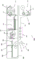
According to the present invention there is also provided a forming device for producing an inductively heatable aerosol-forming rod according to the present invention and as described herein. The forming device comprises:
-a core forming device configured to aggregate a core material comprising at least one of a first aerosol-forming substrate and a first flavouring material into a continuous core strand such that, after passing through the core forming device, the continuous core strand has a cross-sectional shape corresponding to the cross-sectional shape of the cylindrical core portion;
-a longitudinal guide for arranging the continuous susceptor profile relative to the continuous core strand so as to laterally abut the continuous core strand when passing through the core forming device, wherein the longitudinal guide extends at least downstream into an upstream section of the core forming device; and
-a sleeve forming device arranged around at least a downstream section of the wick forming device and configured for gathering sleeve material comprising at least one of the filling material, the second aerosol-forming substrate and the second flavouring material into a continuous sleeve strand surrounding the continuous wick strand and the continuous susceptor profile, such that after passing through the sleeve forming device, the continuous sleeve strand has a cross-sectional shape corresponding to a cross-sectional shape of the sleeve portion.
Advantageously, the forming device allows the different components of the aerosol-forming rod to be efficiently assembled into the desired geometry of the aerosol-forming rod to be manufactured. In particular, the forming means make it possible to ensure an accurate arrangement of each component in terms of position and shape within respective tolerances.
To gather the core material into a continuous core strand, the core forming device preferably comprises an internal funnel. In this regard, the core forming means comprises a substantially tubular body. The substantially tubular body may comprise at least one converging section, in particular at least one conical converging section. Preferably, the at least one converging section is at an upstream end of the core forming device. With respect to the longitudinal centre axis of the forming device, the axial length of the at least one converging section may be at least 10%, in particular at least 20%, preferably at least 30% of the axial length of the core forming device. The shape of the inner cross-section, in particular of the downstream section of the core forming device, preferably corresponds to the cross-sectional shape of the cylindrical core portion. Preferably, the gathering occurs in a transverse direction relative to the direction of travel of the core material through the core forming device. Depending on the radial position of the wick portion in the aerosol-forming rod, the central axis of the inner funnel may be coaxial with the longitudinal central axis of the forming device according to the invention.
The longitudinal guide advantageously facilitates the realization of a position of the susceptor profile in the final aerosol-forming rod corresponding to its predetermined position. In addition, the longitudinal guides are also advantageous in view of maintaining the dimensional stability of the susceptor profile after passing through the forming means, in particular the core forming means. Even more preferably, the longitudinal guide may be used to initially separate the susceptor profile from the core material in the upstream end of the core forming device.
The longitudinal guide may comprise a guide rail or a guide support having a flat guide surface for guiding the continuous susceptor profile. This may be advantageous in particular in the case of a continuous susceptor profile in the form of a strip. Alternatively, the longitudinal guide may comprise a guide tube. Preferably, the guide tube has an inner cross-sectional profile substantially corresponding to the outer cross-sectional profile of the susceptor profile. This may be particularly advantageous for proper guidance of the susceptor profile.
According to the invention, the longitudinal guide extends at least downstream into the upstream section of the core forming device. Advantageously, this may allow to additionally guide the susceptor profile through the forming device in a direction perpendicular to the direction of travel, in addition to the longitudinal guides. As used herein, the term "upstream section of the core forming device" refers to the first stage of the core forming device in which the core material is at least partially gathered but has not yet reached a final shape. Specifically, after passing through the upstream section of the core forming device, the core material is at least partially gathered in a loose arrangement. In this case, "loose" means that the core material has not at this point aggregated into a final, more cohesive form. The at least partially gathered core material may have any form or shape, in particular a strip, but has a lower density (or larger diameter) than the final strip after passing completely through the core forming means.
In particular, the longitudinal guide and the upstream section of the core forming device may define a guide channel or guide tube through which the susceptor profile may pass. As mentioned above, the guide channel or tube preferably has an inner cross-sectional profile which substantially corresponds to the outer cross-sectional profile of the susceptor profile. This may be particularly advantageous for proper guidance of the susceptor profile.
Preferably, the susceptor profile is not guided at the downstream end of the upstream section or further downstream of the upstream section of the core forming means. In particular, the longitudinal guides may extend downstream only into the upstream section of the core forming device. The longitudinal guides may also extend further downstream of the upstream section of the core forming device.
The downstream end of the longitudinal guide may be located upstream of the downstream end of the core forming device.
Thus, the longitudinal guide may be configured for guiding the susceptor profile along at least 25%, in particular at least 50%, preferably at least 75%, more preferably at least 90% or 100% of the length of the core forming device. For this purpose, the longitudinal guides may extend along at least 25%, in particular at least 50%, preferably at least 75%, more preferably at least 90% or 100% of the length of the core forming device. Preferably, the upstream end of the longitudinal guide is located upstream of the upstream end of the core forming device. This ensures that the susceptor profile is accurately pre-positioned in the desired final position within the aerosol-forming rod, i.e. upstream of the wick forming means, before entering the wick forming means.
Also, the core forming device may extend at least downstream into an upstream section of the sleeve forming device. Advantageously, this ensures proper placement of the core material at a predetermined location in the final aerosol-forming rod. In particular, the sleeve forming means is arranged only around the downstream section of the core forming means. Also, the downstream end of the core forming means may be located upstream of the downstream end of the sleeve forming means.
As used herein, the term "upstream section of the sleeve forming device" refers to the first stage of the sleeve forming device in which sleeve material is at least partially gathered but has not yet reached a final shape. In particular, after passing through the upstream section of the sleeve forming device, the sleeve material is gathered at least partially in a loose arrangement. In this case, "loose" means that the sleeve material has not at this point been agglomerated into a final, more cohesive form. The at least partially gathered sleeve material may have any form or shape, in particular a strip, but has a lower density (or larger diameter) than the final strip after passing completely through the sleeve forming means.
As described above in relation to the longitudinal guide, the core forming means may extend along at least 25%, in particular at least 50%, preferably at least 75%, more preferably at least 90% or 100% of the length of the sleeve forming means. The upstream end of the core forming means may be located at or upstream of the upstream end of the sleeve forming means.
In order to adjust the position of the longitudinal guides relative to the core forming device in at least one direction, the forming device may comprise a first translation stage. Preferably, the first translation stage is configured to adjust at least the axial position of the longitudinal guides with respect to the core forming device. As used herein, the term "axial" refers to the direction of travel of the susceptor profile, core material, and sleeve material through the forming device, and particularly refers to the longitudinal central axis of the forming device. The adjustability of the axial position of the longitudinal guide relative to the core forming device enables adjustment of the axial position at which the susceptor profile and the core material meet, in particular in case the longitudinal guide is configured to initially separate the susceptor profile from the core material at an upstream section of the core forming device. Additionally or alternatively, the first translation may also be configured to adjust the position of the longitudinal guide relative to the core forming device in at least one, in particular two, transverse directions perpendicular to the axial direction. The two transverse directions are preferably perpendicular to each other.
To adjust the position of the core forming device relative to the sleeve forming device, the forming device may include a second translation stage. Preferably, the second translation stage is configured to adjust the position of the core forming means relative to the sleeve forming means in at least one direction, in particular in at least one transverse direction, preferably in at least two transverse directions. The two transverse directions are preferably perpendicular to each other. As used herein, the term "transverse" refers to a direction perpendicular to the direction of travel of the susceptor profile, core material and sleeve material through the forming device, and particularly refers to the longitudinal central axis of the forming device. Additionally or alternatively, the second translation stage may also be configured to adjust the axial position of the core forming device relative to the sleeve forming device, i.e. in a direction parallel to the direction of travel, in particular parallel to the longitudinal centre axis of the forming device.
The first translation stage and the second translation stage may be part of a translation stage system of the forming apparatus.
To gather the sleeve material into a continuous sleeve strand around a continuous core strand and a continuous susceptor, the sleeve forming device may include an outer funnel. The outer funnel may be arranged around at least a downstream section of the core forming device, i.e. a section of the core forming device downstream of an upstream section of the core forming device, as further defined above.
The forming device may further comprise one or more guide fins arranged at an inner surface of the sleeve forming device, in particular at an inner surface of the outer funnel. Alternatively or additionally, the forming means may comprise one or more guide fins arranged at an outer surface of the core forming means, in particular at an outer surface of the inner funnel. The guide fins are configured to guide the sleeve material toward a downstream end of the sleeve forming device. Advantageously, the guide fins may help reduce undesirable heating of the sleeve forming device and the core forming device during sleeve formation, which may occur due to friction between the sleeve material and the inner surface of the sleeve forming device and the outer surface of the core forming device, respectively.
Preferably, the one or more guide fins are helically twisted with respect to the direction of travel of the sleeve material through the forming device. In particular, the one or more guide fins may extend along the entire length dimension of the core forming device or the sleeve forming device, respectively, preferably helically. The one or more guide fins may have a triangular cross-section or a semi-oval or semi-elliptical cross-section as seen in a cross-section perpendicular to the longitudinal axis of the forming device. In the latter two configurations, the semi-main axis of the semi-oval or semi-elliptical cross-section is preferably arranged perpendicularly with respect to the longitudinal axis of the forming device, in particular may be radially arranged with respect to the longitudinal central axis of the forming. The cross section of the one or more guide fins may vary, in particular vary in size. For example, the cross-section of one or more guide fins may decrease along the direction of travel of the sleeve material through the forming device. Likewise, the height of the one or more guide fins, i.e. the dimension of the one or more fins in the radial direction with respect to the longitudinal axis of the forming device, may vary, in particular may decrease along the direction of travel of the sleeve material through the forming device.
The one or more guide fins may be interrupted along the length dimension, i.e. substantially along the direction of travel of the sleeve material through the forming device.
In particular, two or more guide fins may be circumferentially arranged at the inner surface of the sleeve forming device. Also, two or more guide fins may be circumferentially arranged at the outer surface of the core forming device.
The one or more guide fins at the inner surface of the sleeve forming means and the one or more guide fins at the outer surface of the core forming means may be arranged at different circumferential positions. In particular, the circumferential position of the one or more guide fins at the inner surface of the sleeve forming means and the circumferential position of the one or more guide fins at the outer surface of the core forming means may be offset by a certain rotational angle, for example by 30 degrees or 60 degrees or 90 degrees or 120 degrees, relative to the longitudinal central axis of the forming means. In particular, the guide fins at the outer surface of the core forming means may be arranged at a circumferential position between, in particular centered, the circumferential positions of two adjacent fins at the inner surface of the sleeve forming means.
Alternatively or in addition to the one or more guide fins, the sleeve forming device may comprise at least one of one or more cooling ribs at an outer surface of the sleeve forming device and one or more cooling openings in a wall of the sleeve forming device. Advantageously, the one or more cooling ribs or the one or more cooling openings may help reduce undesired heating of the sleeve forming device during the sleeve forming process, which may occur due to friction between the sleeve material and the inner surface of the sleeve forming device.
The forming device may be part of an integrated manufacturing device for manufacturing aerosol-forming rods, in particular aerosol-forming rods according to the invention.
The present invention therefore also provides a manufacturing apparatus for manufacturing an aerosol-forming rod, in particular an aerosol-forming rod according to the present invention, wherein the manufacturing apparatus comprises a forming apparatus according to the present invention and as described herein.
Downstream of the forming device, the manufacturing device may further comprise a strip forming device for completing, in particular forming, the entity of the continuous core strand, susceptor profile and continuous sleeve strand into a continuous aerosol-forming strand. The strip forming means may comprise an accessory strip in the form of a continuous conveyor belt. The garniture belt preferably interacts with at least one half-funnel to form a final strip shape and preferably provides a solid wrapper around the continuous core strand, susceptor profile and continuous sleeve strand. Preferably, the garniture belt is arranged below the central axis of the strip forming device, while the at least one half-funnel is arranged above the central axis and thus above the garniture belt.
The garniture belt can support the wrappage. The packages may be supplied by a package supply device into the upstream end of the strip forming device. The package supply means may for example comprise a package bobbin. Preferably, the wrapper is supported on a surface of the garniture belt facing the central axis. Thus, in operation, the wrapper is automatically wrapped around the continuous sleeve strand. The package supply means may also add glue to at least a portion of the package to retain the package around the sleeve portion.
At its downstream end, the rod forming device provides a continuous aerosol-forming strand having a final rod shape, preferably completely surrounded by a wrapper.
Downstream of the rod forming device, the manufacturing device may further comprise a cutting device for cutting the continuous aerosol-forming strand into individual inductively heatable aerosol-forming rods according to the present invention and as described herein.
The manufacturing device may comprise susceptor supply means configured for supplying the susceptor profile to the guide means. The susceptor supply device may comprise an unwinding unit for unwinding a susceptor profile arranged on a reel.
The manufacturing apparatus may further include a sleeve material supply device configured to supply the sleeve material to the sleeve forming device. The sleeve material supply device may include an unwinding unit for unwinding the sleeve material disposed on the bobbin.
The manufacturing apparatus may further include a core material supply device configured to supply the core material to the core forming device. The core material supply device may include an unwinding unit for unwinding the core material disposed on the bobbin.
Downstream of at least one of the sleeve material supply, the susceptor supply and the core material supply, the manufacturing apparatus may further comprise one or more processing units for pre-processing the sleeve material, the susceptor profile and the core material, respectively. The processing units may be configured for physical processing of the sleeve material, the susceptor profile or the core material, respectively. For example, the processing unit may be configured for crimping a sleeve or core material, in particular a sleeve or core material comprising a cast leaf material or an acetate tow. Alternatively or additionally, the physical treatment of the sleeve or core material may comprise one or more of an ionisation treatment, a corona treatment, preheating the sleeve or core material.
The processing unit for the susceptor profile may be configured to produce a plurality of perforations in the susceptor profile and to stretch the perforated susceptor profile at least in a first direction so as to produce an expanded susceptor profile comprising a plurality of openings originating from the plurality of perforations.
The manufacturing apparatus may further include a tensioning unit for adjusting tensions of the sleeve material and the core material, respectively.
The manufacturing apparatus may further comprise a dispensing unit for applying at least one of a fluid, granules, particles and powder to the sleeve material and the core material, respectively. The manufacturing apparatus may further include respective buffer units for buffering the sleeve material and the core material, respectively. In particular, the manufacturing apparatus may include at least one of a processing unit, a tensioning unit, a dispensing unit, and a buffer for each of the sleeve material and the core material.
Further features and advantages of the device according to the invention have been described with respect to an aerosol-forming rod and an aerosol-generating article, and are equally applicable.
The invention will be further described, by way of example only, with reference to the accompanying drawings, in which:
fig. 1 is a schematic illustration of an inductively heatable aerosol-generating article comprising an inductively heatable aerosol-forming rod according to an exemplary embodiment of the present invention;
FIG. 2 is a cross-sectional view of the article according to FIG. 1;
figure 3 schematically illustrates the manufacture of an inductively heatable aerosol-forming rod according to the present invention;
figure 4 is a schematic view of a forming device for producing an inductively heatable aerosol-forming rod according to figure 3; and
figure 5 is a detail of an example of a susceptor of the aerosol-forming rod according to figure 1.
Figures 1 and 2 schematically show exemplary embodiments of an inductively heatable aerosol-generating article according to the present invention. The article 1 has substantially the shape of a strip and comprises four elements arranged in coaxial alignment along a longitudinal axis 7 of the article 1: an aerosol-forming rod 10, a support element 60, an aerosol-cooling element 70 and a filter element 80 according to the present invention. The aerosol-forming rod 10 is arranged at the distal end 2 of the article 1, while the filter element 80 is arranged at the distal end 3 of the article 1. Optionally, the article 1 may further comprise a distal front element 60 which may be used to cover and protect the distal front end of the aerosol-forming rod 10. Each of the foregoing elements is substantially cylindrical, all of which have substantially the same diameter. In addition, these elements are defined by an outer wrapper 90 in order to hold the elements together and maintain the desired circular cross-sectional shape of the strip-like article 1. Preferably, the wrapper 90 is made of paper.
The length of the rod-shaped aerosol-generating article 1 may be between 30 mm and 110 mm, preferably between 40 mm and 60 mm. Also, the diameter of the article 1 may be between 3 and 10 mm, preferably between 5.5 and 8 mm.
The support element 60 may comprise a cartoon-based or cellulose-based tube 62 having a central air passage 61 that allows mixing and homogenisation of any aerosol generated inside the aerosol-forming rod 10. Alternatively, the support element 60 may be used to keep different aerosols generated at different locations inside the aerosol-forming rod separate until reaching the aerosol-cooling element 70.
The aerosol-cooling element 70 is primarily intended to reduce the temperature of the aerosol towards the proximal end 3 of the article 1. The aerosol-forming element may for example comprise a biodegradable polymeric material, a cellulose-based material having a low porosity, or a combination of these and other materials.
The filter element 80 may comprise standard filter material, such as low density acetate tow.
The filter element 80 alone or both the aerosol-cooling element 70 and the filter element 80 may serve as a mouthpiece through which the aerosol exits the aerosol-generating article 1.
In the embodiment shown in fig. 1 and 2, the aerosol-forming rod segment 10 has a cylindrical shape with a constant cross-section (e.g. a circular cross-section). As part of the article 1, the aerosol-forming rod 10 may have a length of between 5 and 20 millimetres, preferably between 7 and 13 millimetres. The diameter of the aerosol-forming rod 10 may be in the range between 3 mm and 10 mm, preferably between 5.5 mm and 8 mm.
As shown in fig. 1 and 2, the aerosol-forming rod comprises at least three components: a cylindrical core portion 30 comprising at least one of a first aerosol-forming substrate and a first flavouring material; an elongate susceptor 40 laterally abutting the cylindrical core portion 30 along the longitudinal axis 7 of the strip 10; and a sleeve portion 20 arranged around the wick portion 30 and susceptor 40 and comprising at least one of a filler material, a second aerosol-forming substrate 21 and a second flavouring material.
In this embodiment, the core portion 30 includes a liquid retaining material 31 impregnated with a liquid (first) flavouring material. In contrast, the sleeve portion 20 comprises a porous substrate based on tobacco fibres, which at least partially form the second aerosol-forming substrate 21. The susceptor 40 is an elongated strip made of ferromagnetic stainless steel. This material may be advantageous because it provides heat due to both eddy currents and hysteresis losses. Optionally, the susceptor 40 may include a nickel coating, wherein nickel is primarily used as a temperature marker as further described above. In addition, the susceptor 40 may comprise a protective coating to prevent undesired ageing of the susceptor 40, for example due to corrosion of the aerosol-forming substrate and flavouring material in a humid environment.
As can also be seen in fig. 1 and 2, the susceptor 40 according to the present embodiment is strip-shaped, with a width dimension in the range between 3.5 and 8 mm, preferably between 4 and 6 mm, and a thickness dimension in the range between 0.05 and 0.4 mm, preferably between 0.15 and 0.35 mm. The core portion 30 is also strip-shaped, having a width dimension in the range between 3.5 and 8 mm, preferably between 4 and 6 mm, and a thickness dimension in the range between 0.5 and 7 mm, preferably between 2 and 5 mm. As can also be seen in fig. 1 and 12, the large side of susceptor 40 laterally abuts the large side of core portion 30. Thus, susceptor 40 is in direct physical contact with core portion 30. Advantageously, this arrangement allows for good heating efficiency of the core portion. In particular, the susceptor 40 may be a susceptor made of an expanded metal sheet comprising a plurality of openings through the sheet. An example of such a susceptor 40 is shown in figure 5.
The contact between the core portion 30 and the susceptor 40 is of a non-bonded nature, i.e., the susceptor 40 and the core portion 30 are not fixedly attached to each other. However, contact between core portion 30 and susceptor 40 may include some non-permanent adhesion, for example due to the wet or moist nature of the liquid holding material impregnated with the liquid seasoning material.
The sleeve portion 20 is arranged around the susceptor 40 and the core portion 30 such that the porous tobacco fibre-based matrix of the sleeve portion 20 completely fills the entire remaining volume of the cylindrical rod 10. In particular, the tobacco fibre-based substrate is in physical contact with the strip-like susceptor 40, substantially with the large side of the susceptor 40 opposite to the large side abutting the core portion 30. Thus, the tobacco fiber-based matrix may be heated simultaneously with the flavoring material in core portion 30. Thus, the aerosol-forming rod 10 allows for the simultaneous production of an aerosol and a flavouring additive. Advantageously, this enhances the variety of aerosols that can be generated.
Inductively heatable aerosol-forming rods according to the invention can be manufactured using a method and manufacturing apparatus 1000 as schematically illustrated in fig. 3.
The manufacturing apparatus 1000 includes a sleeve material supply apparatus 200 configured to supply a sleeve material 201 to the sleeve forming apparatus 130 of the forming apparatus 100. The sleeve material supply device 200 includes an unwinding unit 210 for unwinding the sleeve material 201 disposed on a bobbin 211. Downstream of the unwinding unit 210, the manufacturing apparatus 1000 further includes a buffer 220 for buffering the sleeve material 201, a processing unit 230 for preprocessing the sleeve material 201, a tensioning unit 600 for adjusting the tension of the sleeve material 201, and a dispensing unit 700. In this embodiment, the processing unit 230 may be configured for physically processing the sleeve material 201, for example, for curling the sleeve material 201. Crimping sleeve material 201 may facilitate forming sleeve portions in forming apparatus 100. The dispensing unit 700 may be used to apply at least one of a fluid, granules, particles and powder to a sleeve material, such as a fluid flavoring material.
With respect to the core portion of the aerosol-forming rod, the manufacturing apparatus 1000 further comprises a core material supply apparatus 300 configured to supply core material 301 to the core forming apparatus 130 of the forming apparatus 100. The core material supply device 300 includes an unwinding unit 310 for unwinding the core material 301 disposed on a bobbin 311.
Likewise, the manufacturing apparatus 1000 comprises a susceptor supply device 400 configured for supplying the susceptor profile 401 to the longitudinal guides 140 of the forming apparatus 100. The susceptor supply device 400 comprises an unwinding unit 410 for unwinding a susceptor profile 401 arranged on a bobbin 411. Downstream of the unwinding unit 410, the manufacturing apparatus 1000 further comprises a processing unit 430 for pre-treating the susceptor profile 401. In this embodiment, the processing unit 430 is configured to produce a plurality of perforations in the susceptor profile 401 and to stretch the perforated susceptor profile 401 at least in a first direction so as to produce an expanded susceptor profile comprising a plurality of openings 441 originating from the plurality of perforations. An example of such an expanded susceptor profile 401 is shown in figure 5.
To obtain an aerosol-forming rod 10 as shown in fig. 1 and 2, it is necessary to combine and shape the sleeve material 201, the core material 301 and the susceptor profile 401 so as to form a core portion, a susceptor and a sleeve portion arranged around the core portion and the susceptor. To this end, the manufacturing apparatus 1000 comprises a forming apparatus 100 which is arranged downstream of the aforementioned units and into which the sleeve material 201, the core material 301 and the susceptor profile 401 are fed simultaneously, as shown in fig. 3.
Fig. 4 shows a detail of the forming device 100, wherein the lower part of fig. 4 is a longitudinal cross-section through the device 100 and the upper part of fig. 4 comprises three transverse cross-sections through the device 100 at three different longitudinal positions as shown in the lower part of fig. 4. In accordance with the present invention, forming apparatus 100 includes sleeve forming apparatus 120, core forming apparatus 130, and longitudinal susceptor guide 140.
In this embodiment, the core forming device 130 comprises an inner funnel 131 configured for gathering the core material 301 into a continuous core strand such that, after passing through the core forming device 301, the continuous core strand has a cross-sectional shape corresponding to the cross-sectional shape of the cylindrical core portion of the aerosol-forming rod to be manufactured. The central axis of the inner funnel is coaxial with the longitudinal central axis 107 of the forming device 100, corresponding to the radial position of the wick portion in the aerosol-forming rod.
The longitudinal guide 140 is configured to arrange the continuous susceptor profile 401 with respect to the continuous core strand so as to laterally abut the continuous core strand in a non-bonded manner after passing through the inner funnel 131. In this embodiment, the longitudinal guide 140 includes a guide rail 141 disposed below the longitudinal central axis 107 of the forming device 100 and extending downstream into an upstream section of the core forming device 130. In the upstream section of the core forming device 130, the core material has been pre-aggregated. The guide rail 141 has a flat guide surface 142 facing away from the longitudinal centre axis 107. The upstream section of the core forming device 130 has a length 109 that is about 30% of the total length 108 of the core forming device 130.
As can be seen in the upper part of fig. 4, the guide surface 142 together with the side and lower walls of the inner funnel 131 forms a guide channel 143 into which the susceptor profile 401 is fed in order to initially separate from the core material 301 in the upstream section of the core forming device 130. At the downstream end of the longitudinal guide 140, the susceptor profile 401 is released from the guide, allowing the susceptor profile 401 to come together with the pre-aggregated first and second core materials at a position corresponding to its predetermined position in the final aerosol-forming rod.
To gather the sleeve material into a continuous sleeve strand around the continuous first and second core strands and the susceptor, the forming apparatus 100 includes a sleeve forming apparatus 120. As with the core forming device 130, the sleeve forming device 120 also includes a funnel, which is an outer funnel 121 disposed around at least a downstream section of the core forming device 130. In this embodiment, the outer funnel 121 extends even along the entire length of the core forming device 130 such that the inner funnel 131 is fully received within the outer funnel 121. The downstream end of the core forming device 130 opens out into the downstream section of the sleeve forming device where the sleeve material has been pre-gathered. Thus, at the downstream end of the core forming device 130, the continuous core strand and susceptor shape laterally abutting the continuous core strand are released into the pre-gathered sleeve material. This may be advantageous for the positional stability of the core portion and susceptor at their desired locations in the final aerosol-forming rod.
As also shown in fig. 4, the forming device 100 further comprises two guide fins 180 arranged at the inner surface of the outer funnel 121 of the sleeve forming device 120. In addition, the forming device 100 includes two guide fins 190 arranged at the outer surface of the inner funnel of the core forming device. The guide fins 180 at the inner surface of the outer funnel 121 and the guide fins 190 at the outer surface of the inner funnel 131 are arranged at different circumferential positions, displaced by 90 degrees with respect to the longitudinal central axis 107 of the forming device. These guide fins 180, 190 are configured to guide the sleeve material toward the downstream end of the sleeve forming device 120. Advantageously, the guide fins 180, 190 may help reduce undesirable heating of the sleeve forming device and the core forming device during the sleeve forming process, which may occur due to friction between different portions of the forming device 100 and the sleeve material.
To adjust the position of the wick portion and susceptor within the aerosol-forming rod, the forming device comprises first and second translation stages 171, 172 operatively coupled to the longitudinal guide 140 and the wick forming device 130, respectively. In the present invention, the first translation stage 171 is configured to adjust the axial position of the longitudinal guide 140 relative to the core forming device 130 along the longitudinal center axis 107 of the forming device 100. This enables the axial position at which the susceptor profile 401 meets the pre-collected core material to be adjusted. The second translation stage 172 is configured to adjust the position of the core forming device 130 relative to the sleeve forming device 120 in three directions, namely, a first direction parallel to the longitudinal center axis 107 of the forming device 100, a second direction perpendicular to the longitudinal center axis 107, and a third direction perpendicular to the second direction and perpendicular to the longitudinal center axis 107. Thus, the location where the continuous core strand and susceptor meet the pre-assembled sleeve material can be controlled in three dimensions.
At the downstream end of the sleeve forming apparatus 120, the continuous sleeve strand core strand, susceptor profile, and the entity of the continuous core strand exit the forming apparatus 100. Within the body, the continuous sleeve strand has a cross-sectional shape corresponding to the cross-sectional shape of the sleeve portion and the continuous core strand has a cross-sectional shape corresponding to the cross-sectional shape of the core portion, wherein the susceptor laterally abuts the continuous core strand.
Referring again to fig. 3, the manufacturing apparatus 100 further comprises a rod forming apparatus 800 downstream of the forming apparatus 100, configured for forming the entity of the continuous core strand, susceptor profile and continuous sleeve strand into a continuous aerosol-forming strand. As described above but not shown in fig. 3, strip forming apparatus 800 may include a garniture belt that interacts with at least one half-funnel to form a final strip shape. The garniture belt may also support packages supplied by a package supply (not shown) into the upstream end of the strip forming apparatus 800. In operation, as the substrate web progressively gathers around the sleeve portion, the wrapper automatically wraps around the substrate web such that a continuous aerosol-forming strand fully enclosed by the wrapper exits the strip forming device 800 at the downstream end thereof.
Downstream of the rod forming device, the manufacturing device 1000 may further comprise a cutting device 900 for cutting the continuous aerosol-forming strand into individual inductively heatable aerosol-forming rods according to the present invention.
Claims (15)
1. An inductively heatable aerosol-forming rod for use in an aerosol-generating article, the aerosol-forming rod comprising:
-at least one cylindrical core portion comprising at least one of a first aerosol-forming substrate and a first flavouring material;
-at least one elongated susceptor laterally abutting the cylindrical core portion in a non-bonded manner along a longitudinal axis of the aerosol-forming rod; and
-a sleeve portion arranged around the wick portion and the susceptor, wherein the sleeve comprises at least one of a filler material, a second aerosol-forming substrate and a second flavouring material.
2. The aerosol-forming rod of claim 1, wherein the wick portion comprises at least one of
-a porous tobacco fibre-based matrix or foam, wherein the tobacco fibres at least partially form the first aerosol-forming matrix;
-a porous matrix or foam based on plant fibres, wherein the plant fibres at least partially form the first aerosol-forming matrix;
-a filler comprising a cut tobacco material, wherein the cut tobacco material at least partially forms the first aerosol-forming substrate;
-a filler comprising cut plant material, wherein the cut plant material at least partially forms the first aerosol-forming substrate;
-a liquid retaining material comprising an aerosol-forming liquid, wherein the aerosol-forming liquid at least partially forms the first aerosol-forming substrate;
-a liquid retaining material comprising at least one flavouring substance, wherein the flavouring substance at least partially forms the first flavouring material;
-cellulose fibres or cellulose-based fibres comprising a flavouring substance, wherein the flavouring substance at least partially forms the first aerosol-forming substrate.
3. An aerosol-forming rod according to any one of the preceding claims, wherein the sleeve portion comprises at least one of:
-a porous tobacco fibre-based substrate or foam, wherein the tobacco fibres at least partially form the second aerosol-forming substrate;
-a porous substrate or foam based on plant fibres, wherein the plant fibres at least partially form the second aerosol-forming substrate;
-a filler comprising a cut tobacco material, wherein the cut tobacco material at least partially forms the second aerosol-forming substrate;
-a charge comprising cut plant material, wherein the cut plant material at least partially forms the second aerosol-forming substrate;
-a liquid retaining material comprising an aerosol-forming liquid, wherein the aerosol-forming liquid at least partially forms the second aerosol-forming substrate;
-a liquid retaining material comprising at least one flavouring substance, wherein the flavouring substance at least partially forms the second flavouring material;
-cellulosic or cellulose-based fibres;
-cellulose fibres or cellulose-based fibres comprising a flavouring substance, wherein the flavouring substance at least partially forms the second flavouring material;
-acetate tow bulking fibers;
-plant swelling fibres; or
-paper.
4. An aerosol-forming rod according to any preceding claim, wherein the second aerosol-forming substrate is different from the first aerosol-forming substrate.
5. An aerosol-forming rod according to any preceding claim in which the susceptor comprises an expanded metal sheet comprising a plurality of openings through the sheet.
6. The aerosol-forming rod according to any one of the preceding claims, wherein the cylindrical core portion has a rectangular cross-section or a square cross-section or a semi-elliptical cross-section or a semi-circular cross-section.
7. An aerosol-forming rod according to any one of the preceding claims, wherein the cylindrical wick portion is arranged symmetrically with respect to a longitudinal centre axis of the aerosol-forming rod, or wherein the cylindrical wick portion is arranged within the aerosol-forming rod such that the longitudinal centre axis of the aerosol-forming rod is in a plane of contact between the cylindrical wick and the susceptor adjoining the cylindrical wick or is coaxial with a line of contact between the cylindrical wick and the susceptor adjoining the cylindrical wick.
8. An aerosol-forming rod according to any one of the preceding claims, wherein the susceptor is strip-shaped, and wherein the width dimension of the strip-shaped susceptor is constant along the longitudinal central axis of the aerosol-forming rod or varies along the longitudinal central axis of the aerosol-forming rod.
9. An aerosol-generating article comprising an inductively heatable aerosol-forming rod according to any preceding claim.
10. A forming device for manufacturing an inductively heatable aerosol-forming rod according to any one of claims 1 to 8, the forming device comprising:
-a core forming device configured for gathering a core material comprising at least one of the first aerosol-forming substrate and the first flavouring material into a continuous core strand such that, after passing through the core forming device, the continuous core strand has a cross-sectional shape corresponding to a cross-sectional shape of the cylindrical core portion;
-a longitudinal guide for arranging a continuous susceptor profile relative to the continuous core strand so as to laterally abut the continuous core strand after passing through the core forming device, wherein the longitudinal guide extends at least downstream into an upstream section of the core forming device;
-a sleeve forming device arranged around at least a downstream section of the wick forming device and configured for gathering a sleeve material comprising at least one of the filler material, the second aerosol-forming substrate and the second flavouring material into a continuous sleeve strand around the continuous wick strand and the continuous susceptor profile, such that after passing through the sleeve forming device the continuous sleeve strand has a cross-sectional shape corresponding to a cross-sectional shape of the sleeve portion.
11. The forming device of claim 10, wherein the longitudinal guide extends downstream only into an upstream section of the core forming device.
12. A forming apparatus according to any one of claims 10 to 11, wherein the core forming apparatus comprises an inner funnel and wherein the sleeve forming apparatus comprises an outer funnel.
13. The forming device of any one of claims 10 to 12, further comprising at least one of:
-a first translation stage for adjusting the position of the longitudinal guide with respect to the core forming device at least in one direction;
-a second translation stage for adjusting the position of the core forming means with respect to the sleeve forming means at least in one direction.
14. A forming device according to any one of claims 10 to 13, further comprising one or more guide fins arranged at least one of an inner surface of the sleeve forming device and an outer surface of the core forming device.
15. The forming device of claim 14, wherein the one or more guide fins are helically twisted with respect to a direction of travel of the sleeve material through the forming device.
Applications Claiming Priority (3)
| Application Number | Priority Date | Filing Date | Title |
|---|---|---|---|
| EP19159886.1 | 2019-02-28 | ||
| EP19159886 | 2019-02-28 | ||
| PCT/EP2020/055088 WO2020174026A1 (en) | 2019-02-28 | 2020-02-27 | Inductively heatable aerosol-forming rods and shaping device for usage in the manufacturing of such rods |
Publications (1)
| Publication Number | Publication Date |
|---|---|
| CN113873902A true CN113873902A (en) | 2021-12-31 |
Family
ID=65635495
Family Applications (1)
| Application Number | Title | Priority Date | Filing Date |
|---|---|---|---|
| CN202080017154.5A Pending CN113873902A (en) | 2019-02-28 | 2020-02-27 | Inductively heatable aerosol-forming rod and forming device for producing such rod |
Country Status (6)
| Country | Link |
|---|---|
| US (1) | US20220132907A1 (en) |
| EP (1) | EP3930488A1 (en) |
| JP (1) | JP2022522157A (en) |
| KR (1) | KR20210132686A (en) |
| CN (1) | CN113873902A (en) |
| WO (1) | WO2020174026A1 (en) |
Cited By (2)
| Publication number | Priority date | Publication date | Assignee | Title |
|---|---|---|---|---|
| WO2023198764A1 (en) * | 2022-04-12 | 2023-10-19 | Philip Morris Products S.A. | Aerosol-generating article with relatively short rod of aerosol-generating substrate |
| WO2023226512A1 (en) * | 2022-05-24 | 2023-11-30 | 云南中烟工业有限责任公司 | Fully-hollow filter rod having triangular partition, and forming method therefor |
Families Citing this family (8)
| Publication number | Priority date | Publication date | Assignee | Title |
|---|---|---|---|---|
| US10517332B2 (en) | 2017-10-31 | 2019-12-31 | Rai Strategic Holdings, Inc. | Induction heated aerosol delivery device |
| US10750787B2 (en) | 2018-01-03 | 2020-08-25 | Cqens Technologies Inc. | Heat-not-burn device and method |
| US11019850B2 (en) | 2018-02-26 | 2021-06-01 | Rai Strategic Holdings, Inc. | Heat conducting substrate for electrically heated aerosol delivery device |
| WO2022074208A2 (en) * | 2020-10-09 | 2022-04-14 | Philip Morris Products S.A. | Applying an additive from within during shaping of a sheet into a rod |
| EP4225057A2 (en) * | 2020-10-09 | 2023-08-16 | Philip Morris Products S.A. | Applying an additive from radially outside upon production of an aerosol-generating rod |
| WO2023135285A1 (en) * | 2022-01-14 | 2023-07-20 | Jt International Sa | Aerosol generating substrate and article containing the substrate |
| WO2023135284A1 (en) * | 2022-01-14 | 2023-07-20 | Jt International Sa | Aerosol generating article |
| WO2023222610A1 (en) * | 2022-05-17 | 2023-11-23 | Philip Morris Products S.A. | Closed loop system and method for controlling a position of a susceptor in an aerosol-generating article |
Citations (4)
| Publication number | Priority date | Publication date | Assignee | Title |
|---|---|---|---|---|
| WO2017182485A1 (en) * | 2016-04-20 | 2017-10-26 | Philip Morris Products S.A. | Hybrid aerosol-generating element and method for manufacturing a hybrid aerosol-generating element |
| CN107529812A (en) * | 2015-05-21 | 2018-01-02 | 菲利普莫里斯生产公司 | For manufacture can sensing heating tobacco rod method |
| WO2018122320A1 (en) * | 2016-12-29 | 2018-07-05 | Philip Morris Products S.A. | Method and apparatus for the production of a component of an aerosol generating article |
| WO2018229087A1 (en) * | 2017-06-15 | 2018-12-20 | Philip Morris Products S.A. | Method and apparatus for manufacturing inductively heatable aerosol-forming rods |
Family Cites Families (3)
| Publication number | Priority date | Publication date | Assignee | Title |
|---|---|---|---|---|
| TWI692274B (en) | 2014-05-21 | 2020-04-21 | 瑞士商菲利浦莫里斯製品股份有限公司 | Inductive heating device for heating an aerosol-forming substrate and method of operating an inductive heating system |
| WO2018002084A1 (en) * | 2016-06-29 | 2018-01-04 | British American Tobacco (Investments) Limited | Article for use with apparatus for heating smokable material |
| CN110602955A (en) * | 2017-05-10 | 2019-12-20 | 菲利普莫里斯生产公司 | Aerosol-generating articles, devices and systems with optimized substrate use |
-
2020
- 2020-02-27 US US17/434,111 patent/US20220132907A1/en active Pending
- 2020-02-27 EP EP20706293.6A patent/EP3930488A1/en active Pending
- 2020-02-27 JP JP2021549829A patent/JP2022522157A/en active Pending
- 2020-02-27 CN CN202080017154.5A patent/CN113873902A/en active Pending
- 2020-02-27 KR KR1020217030414A patent/KR20210132686A/en unknown
- 2020-02-27 WO PCT/EP2020/055088 patent/WO2020174026A1/en active Search and Examination
Patent Citations (5)
| Publication number | Priority date | Publication date | Assignee | Title |
|---|---|---|---|---|
| CN107529812A (en) * | 2015-05-21 | 2018-01-02 | 菲利普莫里斯生产公司 | For manufacture can sensing heating tobacco rod method |
| WO2017182485A1 (en) * | 2016-04-20 | 2017-10-26 | Philip Morris Products S.A. | Hybrid aerosol-generating element and method for manufacturing a hybrid aerosol-generating element |
| CN109068741A (en) * | 2016-04-20 | 2018-12-21 | 菲利普莫里斯生产公司 | Mix aerosol producing element and the method for manufacturing mixing aerosol producing element |
| WO2018122320A1 (en) * | 2016-12-29 | 2018-07-05 | Philip Morris Products S.A. | Method and apparatus for the production of a component of an aerosol generating article |
| WO2018229087A1 (en) * | 2017-06-15 | 2018-12-20 | Philip Morris Products S.A. | Method and apparatus for manufacturing inductively heatable aerosol-forming rods |
Cited By (2)
| Publication number | Priority date | Publication date | Assignee | Title |
|---|---|---|---|---|
| WO2023198764A1 (en) * | 2022-04-12 | 2023-10-19 | Philip Morris Products S.A. | Aerosol-generating article with relatively short rod of aerosol-generating substrate |
| WO2023226512A1 (en) * | 2022-05-24 | 2023-11-30 | 云南中烟工业有限责任公司 | Fully-hollow filter rod having triangular partition, and forming method therefor |
Also Published As
| Publication number | Publication date |
|---|---|
| JP2022522157A (en) | 2022-04-14 |
| WO2020174026A1 (en) | 2020-09-03 |
| EP3930488A1 (en) | 2022-01-05 |
| KR20210132686A (en) | 2021-11-04 |
| US20220132907A1 (en) | 2022-05-05 |
Similar Documents
| Publication | Publication Date | Title |
|---|---|---|
| CN113873902A (en) | Inductively heatable aerosol-forming rod and forming device for producing such rod | |
| AU2018200641B2 (en) | Blended rods for use in aerosol-generating articles | |
| CN113597263B (en) | Inductively heatable aerosol-forming rod and forming device for producing such a rod | |
| CN113473871A (en) | Inductively heatable aerosol-forming rod and forming device for producing such rod | |
| US20220132908A1 (en) | Inductively heatable aerosol-generating article, method for manufacturing such an article and an apparatus for manufacturing a susceptor of such an article | |
| US20230087804A1 (en) | Aerosol-generating article including novel substrate and upstream element | |
| CN115379770A (en) | Aerosol-generating article with dual hollow tubular sections | |
| CN115297740A (en) | Ventilated aerosol-generating article with induction heating | |
| CN115605099A (en) | Ventilated aerosol-generating article with upstream porous segment | |
| CN115297739A (en) | Aerosol-generating article with improved configuration | |
| CN115379773A (en) | Aerosol-generating article with elongate susceptor | |
| CN116528699A (en) | Aerosol-generating article with low resistance to draw and improved flavor delivery | |
| RU2802861C2 (en) | Induction heated aerosol producing rods and forming device for use in manufacturing of such rods | |
| RU2802992C2 (en) | Induction heated aerosol genrating rods and shaper for use in production of such rods | |
| RU2802863C2 (en) | Induction heated aerosol producing rods and forming device for use in manufacturing such rods | |
| BR112021016823A2 (en) | INDUCTIVELY HEATED AEROSOL FORMING COLUMNS AND SHAPING DEVICE FOR USE IN THE MANUFACTURE OF SUCH COLUMNS | |
| BR112021016715A2 (en) | INDUCTIVELY HEATED AEROSOL FORMING COLUMNS AND SHAPING DEVICE FOR USE IN THE MANUFACTURE OF SUCH COLUMNS | |
| CN116419684A (en) | Aerosol-generating article with non-homogenized tobacco matrix | |
| CN115915975A (en) | Aerosol-generating article with improved construction | |
| CN116568159A (en) | Aerosol-generating article with coated susceptor element |
Legal Events
| Date | Code | Title | Description |
|---|---|---|---|
| PB01 | Publication | ||
| PB01 | Publication | ||
| SE01 | Entry into force of request for substantive examination | ||
| SE01 | Entry into force of request for substantive examination |