CN113863676B - Concrete horizontal transportation device for roof construction - Google Patents
Concrete horizontal transportation device for roof construction Download PDFInfo
- Publication number
- CN113863676B CN113863676B CN202111244617.4A CN202111244617A CN113863676B CN 113863676 B CN113863676 B CN 113863676B CN 202111244617 A CN202111244617 A CN 202111244617A CN 113863676 B CN113863676 B CN 113863676B
- Authority
- CN
- China
- Prior art keywords
- frame
- transportation
- concrete
- water tank
- stirring
- Prior art date
- Legal status (The legal status is an assumption and is not a legal conclusion. Google has not performed a legal analysis and makes no representation as to the accuracy of the status listed.)
- Active
Links
Images


Classifications
-
- E—FIXED CONSTRUCTIONS
- E04—BUILDING
- E04G—SCAFFOLDING; FORMS; SHUTTERING; BUILDING IMPLEMENTS OR AIDS, OR THEIR USE; HANDLING BUILDING MATERIALS ON THE SITE; REPAIRING, BREAKING-UP OR OTHER WORK ON EXISTING BUILDINGS
- E04G21/00—Preparing, conveying, or working-up building materials or building elements in situ; Other devices or measures for constructional work
- E04G21/02—Conveying or working-up concrete or similar masses able to be heaped or cast
- E04G21/04—Devices for both conveying and distributing
-
- B—PERFORMING OPERATIONS; TRANSPORTING
- B28—WORKING CEMENT, CLAY, OR STONE
- B28C—PREPARING CLAY; PRODUCING MIXTURES CONTAINING CLAY OR CEMENTITIOUS MATERIAL, e.g. PLASTER
- B28C5/00—Apparatus or methods for producing mixtures of cement with other substances, e.g. slurries, mortars, porous or fibrous compositions
- B28C5/08—Apparatus or methods for producing mixtures of cement with other substances, e.g. slurries, mortars, porous or fibrous compositions using driven mechanical means affecting the mixing
- B28C5/10—Mixing in containers not actuated to effect the mixing
- B28C5/12—Mixing in containers not actuated to effect the mixing with stirrers sweeping through the materials, e.g. with incorporated feeding or discharging means or with oscillating stirrers
- B28C5/14—Mixing in containers not actuated to effect the mixing with stirrers sweeping through the materials, e.g. with incorporated feeding or discharging means or with oscillating stirrers the stirrers having motion about a horizontal or substantially horizontal axis
-
- E—FIXED CONSTRUCTIONS
- E04—BUILDING
- E04D—ROOF COVERINGS; SKY-LIGHTS; GUTTERS; ROOF-WORKING TOOLS
- E04D15/00—Apparatus or tools for roof working
- E04D15/07—Apparatus or tools for roof working for handling roofing or sealing material in bulk form
-
- E—FIXED CONSTRUCTIONS
- E04—BUILDING
- E04G—SCAFFOLDING; FORMS; SHUTTERING; BUILDING IMPLEMENTS OR AIDS, OR THEIR USE; HANDLING BUILDING MATERIALS ON THE SITE; REPAIRING, BREAKING-UP OR OTHER WORK ON EXISTING BUILDINGS
- E04G21/00—Preparing, conveying, or working-up building materials or building elements in situ; Other devices or measures for constructional work
- E04G21/02—Conveying or working-up concrete or similar masses able to be heaped or cast
- E04G21/04—Devices for both conveying and distributing
- E04G21/0409—Devices for both conveying and distributing with conveyor belts
-
- E—FIXED CONSTRUCTIONS
- E04—BUILDING
- E04G—SCAFFOLDING; FORMS; SHUTTERING; BUILDING IMPLEMENTS OR AIDS, OR THEIR USE; HANDLING BUILDING MATERIALS ON THE SITE; REPAIRING, BREAKING-UP OR OTHER WORK ON EXISTING BUILDINGS
- E04G21/00—Preparing, conveying, or working-up building materials or building elements in situ; Other devices or measures for constructional work
- E04G21/24—Safety or protective measures preventing damage to building parts or finishing work during construction
- E04G21/246—Safety or protective measures preventing damage to building parts or finishing work during construction specially adapted for curing concrete in situ, e.g. by covering it with protective sheets
Abstract
The invention relates to the technical field of concrete transportation, in particular to a horizontal concrete transportation device for roof construction, which comprises a moving frame, rollers, support columns, a transportation frame, a stirring mechanism and a guide frame, wherein in the stirring mechanism, the concrete is stirred by stirring blades in the rotation process of a stirring shaft, so that the phenomenon that the subsequent use effect of the concrete is influenced due to uneven distribution of stones and slurry caused by the sinking of the stones in the concrete in transportation is avoided; in the guide frame, a support frame rotates and can drive the guide frame through mutually supporting with No. two support frames and rotate, and then can drive the guide frame and rotate the different position departments of roofing to can realize the pouring to roofing corner concrete, improve the efficiency of pouring of concrete.
Description
Technical Field
The invention relates to the technical field of concrete transportation, in particular to a horizontal concrete transportation device for roof construction.
Background
The concrete is artificial stone which is prepared by taking cement as a main cementing material, mixing water, sand and stones with chemical additives and mineral admixtures if necessary, uniformly stirring, densely molding, curing and hardening according to a proper proportion, and is widely applied to occasions such as building construction, road construction and the like due to the characteristics of rich raw materials, low cost, good plasticity, strong strength, good durability and the like of the concrete; after the building construction is finished, the roof needs to be sealed, and concrete needs to be used for pouring and sealing the roof in the roof sealing process, so that a concrete transportation device needs to be used for transporting and processing the concrete.
At present, the following problems exist in the transportation process of roof construction of concrete: a. the concrete needs to be subpackaged and transported after being conveyed to the roof by ground equipment, and because the concrete is in a relatively static state in the subpackaging and transporting process, the concrete is easy to generate a stone sinking phenomenon, so that the concrete pouring effect is poor due to the uneven distribution ratio of stones and mortar in the pouring and pouring process of the concrete, and the capping effect of the roof is influenced; b. because the roofing is square structure usually, because current concrete placement equipment is difficult for stretching into roofing corner department in traditional concrete placement process, generally use the method of artifical concreting to carry out the pouring to the roofing, lead to workman's work load to aggravate, and then influence the efficiency of roofing.
Disclosure of Invention
In order to solve the problems, the invention adopts the following technical scheme: the utility model provides a horizontal conveyer of concrete for roofing construction, is including removing frame, gyro wheel, support column, transportation frame, rabbling mechanism and guide frame, removal frame under four corners of terminal surface seted up the removal recess, remove recess internally mounted and have the gyro wheel, remove the frame up end and be provided with two sets of support columns, symmetrical installation is in removing the frame up end around every group support column, the transportation frame is installed jointly to the support column up end, transportation frame internally mounted has the rabbling mechanism, the discharge gate has been seted up on the inside terminal surface right side of terminal surface down of transportation frame, remove the frame up end and be located the discharge gate below and install the guide frame.
Rabbling mechanism include agitator motor, (mixing) shaft, seal gasket, stirring vane, open plate and clean branch chain, wherein the (mixing) shaft right-hand member pass through the bearing and install on the inside right side wall of transportation frame, (mixing) shaft left end passes the transportation frame and passes through the bearing and install on the wall of transportation frame left side, agitator motor passes through the motor cabinet and installs on the outer wall of transportation frame left side, agitator motor output shaft and (mixing) shaft left end fixed connection, seal gasket is installed with the part of transportation frame contact in the (mixing) shaft left side, install the spiral stirring vane that to the right on the (mixing) shaft, just be located the discharge gate right side on the transportation frame and seted up the logical groove that opens and shuts, open plate passes open and shut logical groove joint inside the screens inslot, all install clean branch chain on inside the transportation frame and the up end.
Preferably, the guide frame include switching-over motor, a support frame, No. two support frames, guide frame, unloading frame and vibration subassembly, wherein the switching-over motor pass through the motor cabinet and install and remove a frame up end, the support frame is installed to switching-over motor output shaft up end, remove a frame up end and seted up the arc wall, the inside slidable mounting of arc wall has No. two support frames, all install the decurrent guide frame of slope from the left hand right side on support frame and No. two support frames, and guide frame rotates and installs on No. two support frames, guide frame internally mounted has the unloading frame, install the vibration subassembly between guide frame and the unloading frame.
Preferably, clean branch chain include electronic slider, clean frame, push pedal, scraper blade, water tank, shower nozzle and water pump, wherein transportation frame front and back section up end left side slide and be provided with electronic slider, clean frame slides and sets up on transportation frame inner wall, clean frame is the Contraband type structure that the opening is decurrent, and clean frame upper end is connected with electronic slider, wherein clean 562 horizontal segment and the mutual joint of vertical section, install the push pedal that leans on with transportation frame lower extreme facial features counterbalance between the vertical section lower extreme of clean frame, the scraper blade is installed to the part of the vertical section of clean frame and inside wall around being close to the transportation frame, the water tank is installed on clean frame horizontal segment, the terminal surface is installed under the water tank and is had a perfect understanding mutually with the inside shower nozzle of water tank, the water tank up end is installed the water pump that has a perfect understanding mutually with the water tank inside.
Preferably, the vibration assembly comprises a reciprocating cylinder, a vibration plate, a connecting block and a return spring rod, wherein the reciprocating cylinder is arranged on the inner wall of the material guide frame through a cylinder seat, the vibrating plate is arranged on the inner wall of the material guide frame in a sliding way and is connected with the telescopic end of the reciprocating cylinder, the connecting block is arranged on the blanking frame, one end of the connecting block, which is far away from the blanking frame, is abutted against the vibrating plate, and the end surface of the vibrating plate contacting with the connecting block is provided with uneven bulges, reset spring rods are symmetrically arranged between the blanking frame and the material guiding frame from left to right, when concrete enters the blanking frame, the reciprocating cylinder is started to drive the vibrating plate to reciprocate, and then the arch on the vibration board drives the blanking frame through linking the piece and carry out reciprocating vibration, guarantees that the concrete can not take place to block up in blanking frame is inside, influences the blanking effect of concrete, and wherein reset spring pole plays to reset and supporting role to the blanking frame in the course of the work.
Preferably, the baffle is installed to the transport frame up end left and right sides, can play the guard action to the concrete that causes to splash owing to rocking in the transportation, avoid the concrete to splash to the transport frame outside.
Preferably, the shower nozzle be provided with two sets ofly, and two sets of shower nozzle bilateral symmetry sets up terminal surface under the water tank, and every group shower nozzle evenly sets up terminal surface under the water tank from preceding backward, the setting of two sets of shower nozzles can all wash the processing to the inside left and right sides wall of transportation frame for clean scope is wider, the shower nozzle can wash the processing to (mixing) shaft and stirring vane in step at the removal in-process simultaneously.
Preferably, the inside regulating plate that is provided with of water tank, adjusting screw is installed through the screw thread in the water tank top, and adjusting screw supports at the regulating plate up end down the terminal surface, the symmetrical regulating spring pole of installing around between regulating plate up end and the inside up end of water tank, the regulating head with shower nozzle matched with is installed to the terminal surface under the regulating plate, and the regulating head is round platform body structure, the air pump that link up with the water tank is installed to the water tank up end. The method comprises the following steps that (1) because the moisture in the concrete is likely to evaporate in the long-distance transportation process, micro-humidification processing needs to be carried out on the concrete in the concrete pouring process, when the humidification processing needs to be carried out on the concrete, the horizontal section and the vertical section of a cleaning frame are separated, an adjusting screw is rotated to drive an adjusting plate to move downwards, an adjusting head is further driven to move downwards, the opening area of a spray head is adjusted to be reduced through a circular table body structure in the downward moving process of the adjusting head, the flow of the spray head is further reduced, and an electric sliding block is started to drive a water tank to carry out micro-humidification processing on the concrete through the spray head; when needs wash the transportation frame, the manual regulation screw that rotates drives the regulation head through the regulating plate and resets, with vertical section and the horizontal segment joint of clean frame again, wherein adjust the spring beam and play support and reset action to the regulating plate in the course of the work, the use of air pump can control water from shower nozzle spun velocity of flow size.
Preferably, transportation frame lower extreme just be located and handle mouthful below and install the spacing frame that leaks hopper-shaped, can play limiting displacement to blanking in-process concrete, avoid the concrete to take place to sputter when the guide frame is inside dropping, cause the pollution of environment.
Preferably, the rollers on the right side are universal wheels, and the universal wheels can be used for reversing through external force in the moving process of the moving frame, so that the moving range of the moving frame is enlarged.
The invention has the beneficial effects that: 1. in the stirring mechanism, the concrete is stirred by the stirring blades in the rotation process of the stirring shaft, so that the condition that stones and slurry are unevenly distributed due to the fact that the stones in the concrete are sunk in the process of transportation and the subsequent use effect of the concrete is influenced is avoided; in the guide frame, a support frame rotates and can drive the guide frame through mutually supporting with No. two support frames and rotate, and then can drive the guide frame and rotate the different position departments of roofing to can realize the pouring to roofing corner concrete, improve the efficiency of pouring of concrete.
2. In the guide frame designed by the invention, the first support frame rotates to drive the guide frame to rotate through being matched with the second support frame, so that concrete can be poured at the corner of a roof, the problem of low efficiency of pouring concrete manually is avoided, in the vibration assembly, the reciprocating cylinder is started to drive the blanking frame to vibrate back and forth through the mutual matching of the protrusions on the vibration plate and the connecting block, the problem that concrete is blocked in the blanking frame due to poor flowability between stones and slurry is avoided, and the concrete blanking is smoother.
Drawings
The invention is further illustrated by the following examples in conjunction with the drawings.
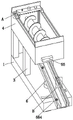
Fig. 1 is a schematic perspective view of a first embodiment of the present invention.
Fig. 2 is a schematic perspective view of a second embodiment of the present invention.
Fig. 3 is a front view of the present invention.
Fig. 4 is a partial cross-sectional view at C-C of fig. 3 of the present invention.
Fig. 5 is a partial enlarged view of fig. 1 a according to the present invention.
Fig. 6 is a partial enlarged view of the invention at B of fig. 1.
Fig. 7 is a schematic view of the internal structure of the water tank of the present invention.
In the figure: 1. a movable frame; 2. a roller; 21. a universal wheel; 3. a support pillar; 4. a transport frame; 41. a baffle plate; 42. a limiting frame; 5. a stirring mechanism; 51. a stirring motor; 52. a stirring shaft; 53. sealing gaskets; 54. a stirring blade; 55. opening and closing the plate; 56. cleaning branched chains; 561. an electric slider; 562. a cleaning frame; 563. pushing the plate; 564. a squeegee; 565. a water tank; 5651. an adjusting plate; 565. adjusting the screw rod; 5653. adjusting the spring rod; 5654. an adjustment head; 5655. an air pump; 566. a spray head; 567. a water pump; 6. a guide frame; 61. a commutation motor; 62. a first support frame; 63. a second support frame; 64. a material guiding frame; 65. a blanking frame; 66. a vibrating assembly; 661. a reciprocating cylinder; 662. a vibrating plate; 663. connecting blocks; 664. a return spring rod.
Detailed Description
The embodiments of the invention will be described in detail below with reference to the drawings, but the invention can be implemented in many different ways as defined and covered by the claims.
Referring to fig. 1 and 2, a horizontal conveyer of concrete for roofing construction, including removing frame 1, gyro wheel 2, support column 3, transportation frame 4, rabbling mechanism 5 and guide frame 6, removal frame 1 under four corners of terminal surface seted up and removed the recess, remove recess internally mounted and have gyro wheel 2, remove 1 up end of frame and be provided with two sets of support columns 3, symmetrical installation is in removing 1 up end around every group support column 3, the transportation frame 4 is installed jointly to support column 3 up end, transportation frame 4 internally mounted has rabbling mechanism 5, the discharge gate has been seted up on the inside lower terminal surface right side of transportation frame 4, remove 1 up end of frame and be located the discharge gate below and install guide frame 6.
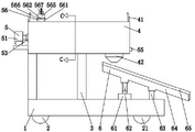
Referring to fig. 3, the right roller 2 is a universal wheel 21, and the universal wheel 21 can be reversed by an external force during the moving process of the moving frame 1, so that the moving range of the moving frame 1 is increased.
Referring to fig. 2, the left side and the right side of the upper end surface of the transportation frame 4 are provided with the baffle plates 41, so that the splashed concrete caused by shaking in the transportation process can be protected, and the concrete is prevented from splashing to the outside of the transportation frame 4.
Referring to fig. 3, the lower end of the transportation frame 4 and the position below the processing port are provided with a funnel-shaped limiting frame 42, so that the concrete can be limited in the blanking process, and the phenomenon that the concrete is sputtered when falling into the guide frame 6 to cause environmental pollution is avoided.
Referring to fig. 1 and fig. 2, the stirring mechanism 5 includes a stirring motor 51, a stirring shaft 52, a sealing gasket 53, a stirring blade 54, an open-close board 55 and a cleaning branched chain 56, wherein the right end of the stirring shaft 52 is mounted on the right side wall inside the transportation frame 4 through a bearing, the left end of the stirring shaft 52 passes through the transportation frame 4 and is mounted on the left side wall of the transportation frame 4 through a bearing, the stirring motor 51 is mounted on the left side outer wall of the transportation frame 4 through a motor base, the output shaft of the stirring motor 51 is fixedly connected with the left end of the stirring shaft 52, the sealing gasket 53 is mounted on the left side of the stirring shaft 52 contacting the transportation frame 4, the stirring shaft 52 is mounted with the stirring blade 54 which is spirally right, the right side of the transportation frame 4 and the right side of the discharge port are provided with an open-close through groove, the left side of the transportation frame 4 and the discharge port are provided with a clamping groove, the open-close board 55 is clamped inside the clamping groove through the open-close through groove, the inside and the upper end surface of the transportation frame 4 are both provided with cleaning branched chains 56.
Referring to fig. 2 and 3, the guide frame 6 includes a reversing motor 61, a first support frame 62, a second support frame 63, a material guiding frame 64, a material discharging frame 65 and a vibration assembly 66, wherein the reversing motor 61 is mounted on the upper end surface of the movable frame 1 through a motor base, the first support frame 62 is mounted on the upper end surface of an output shaft of the reversing motor 61, an arc-shaped groove is formed in the upper end surface of the movable frame 1, the second support frame 63 is slidably mounted inside the arc-shaped groove, the material guiding frame 64 inclining downwards from left to right is mounted on the first support frame 62 and the second support frame 63, the material guiding frame 64 is rotatably mounted on the second support frame 63, the material discharging frame 65 is mounted inside the material guiding frame 64, and the vibration assembly 66 is mounted between the material guiding frame 64 and the material discharging frame 65.
When the concrete pouring device works, concrete is pumped into the transportation frame 4 from the forming device through the existing equipment, the mobile frame 1 is pushed by external force to drive the concrete in the transportation frame 4 to move to a working position through the roller 2, after the transportation frame 4 drives the concrete to move to the working position, according to the position of concrete pouring required by a roof, the reversing motor 61 is started to drive the first support frame 62 to rotate, the first support frame 62 is matched with the second support frame 63 to drive the material guiding frame 64 to rotate in the rotating process, further, the material discharging frame 65 is driven to rotate to the working position, after the guide frame 6 is moved to the working position, the opening plate 55 is opened, the stirring motor 51 is started to drive the stirring shaft 52 to rotate, the stirring blades 54 are driven to rotate in the rotating process of the stirring shaft 52, further, the concrete is driven to fall into the concrete pouring position from the material discharging port through the material discharging frame 65, wherein the stirring blades 54 which are spirally turned right can stir the transported concrete, make and mix more evenly between stone and the thick liquids, guarantee that the composition distributes evenly between the concrete, improve the subsequent result of use of concrete, stirring vane 54 rotates the in-process and can carry left concrete to near the discharge gate again, improve the blanking efficiency of concrete, seal gasket 53 can play sealed effect in the course of the work, avoid the concrete to leak, the use of clean branch chain 56 can be washd transportation frame 4 after the transportation, vibration subassembly 66 can carry out vibration treatment to blanking frame 65 in the course of the work, avoid the concrete to block up in blanking frame 65, influence the blanking effect of concrete.
Referring to fig. 3 and 4, the cleaning branch 56 includes an electric slider 561, a cleaning frame 562, a push plate 563, a scraper 564, a water tank 565, a spray head 566 and a water pump 567, wherein the left side of the upper end surface of the front and rear sections of the transportation frame 4 is provided with an electric slider 561 in a sliding way, the cleaning frame 562 is arranged on the inner wall of the transportation frame 4 in a sliding way, the cleaning frame 562 is in an Contraband type structure with a downward opening, the upper end of the cleaning frame 562 is connected with the electric slider 561, wherein clean the mutual joint of frame 562 horizontal segment and vertical section, install between the vertical section lower extreme of clean frame 562 and transport the push pedal 563 that the terminal surface leaned on under the frame 4, clean the vertical section of frame 562 and near the part of inside wall install the scraper blade 564 around the transport frame 4, water tank 565 installs on clean the frame 562 horizontal segment, the terminal surface is installed under the water tank 565 and is had a shower nozzle 566 that link up with the inside of water tank 565 mutually, the water tank 565 up end is installed and is had a water pump 567 that link up with the inside of water tank 565 mutually. When the concrete works, after concrete in the transportation frame 4 is discharged, the electric slider 561 is started to drive the cleaning frame 562 to move from left to right, and further drive the push plate 563 to push the residual concrete on the lower end face in the transportation frame 4 to right, and finally the residual concrete is discharged through the discharge port, the push plate 563 is synchronously driven in the moving process of the cleaning frame 562 to scrape off the residual concrete adhered to the side wall of the transportation frame 4, wherein the push plate 563 and the scraper 564 are matched with each other to scrape the residual concrete in the transportation frame 4, so as to prevent the concrete from condensing in the transportation frame 4 and influencing the next use of the transportation frame 4, when the push plate 563 moves the rightmost side of the transportation frame 4, the moving frame 1 is pushed to move to a non-working position through the rollers 2, the electric slider 561 drives the cleaning frame 562 to reset, the electric slider 561 is continuously started to drive the cleaning frame 562, the water pump 567 is started to pump water into the water tank 565, water passes through water tank 565 and outwards sprays through shower nozzle 566, can wash transportation frame 4 inner wall and (mixing) shaft 52, stirring vane 54 among the water jet process, and the waste liquid after the washing flows out from the discharge gate, avoids the concrete to adhere to in transportation frame 4, causes the corrosion of transportation frame 4 inner wall, influences the life of transportation frame 4.
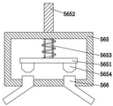
Referring to fig. 3 and 7, an adjusting plate 5651 is arranged inside the water tank 565, an adjusting screw 5652 is installed above the water tank 565 through threads, the lower end face of the adjusting screw 5652 abuts against the upper end face of the adjusting plate 5651, adjusting spring rods 5653 are symmetrically installed between the upper end face of the adjusting plate 5651 and the upper end face inside the water tank 565 in a front-back manner, an adjusting head 5654 matched with the spray head 566 is installed on the lower end face of the adjusting plate 5651, the adjusting head 5654 is of a circular truncated cone structure, and an air pump 5655 communicated with the inside of the water tank 565 is installed on the upper end face of the water tank 565. The water in the concrete is likely to evaporate in the long-distance transportation process, so that micro-humidification treatment needs to be performed on the concrete in the pouring process of the concrete, when the humidification treatment needs to be performed on the concrete, the horizontal section and the vertical section of the cleaning frame 562 are separated, the adjusting screw 5652 is rotated to drive the adjusting plate 5651 to move downwards, the adjusting head 5654 is driven to move downwards, the opening area of the spray nozzle 566 is adjusted to be reduced through the circular table body structure in the downward movement process of the adjusting head 5654, the flow of the spray nozzle 566 is reduced, and the electric slider 561 is started to drive the water tank 565 to perform micro-humidification treatment on the concrete through the spray nozzle 566; when the transportation frame 4 needs to be cleaned, the adjusting screw 5652 is manually rotated to drive the adjusting head 5654 to reset through the adjusting plate 5651, then the vertical section and the horizontal section of the cleaning frame 562 are clamped, the adjusting spring 5653 plays a role in supporting and resetting the adjusting plate 5651 in the working process, and the air pump 5655 can control the flow rate of water sprayed out of the spray head 566.
Referring to fig. 3, two sets of spray heads 566 are provided, and the two sets of spray heads 566 are symmetrically arranged on the lower end surface of the water tank 565 from left to right, and each set of spray heads 566 is uniformly arranged on the lower end surface of the water tank 565 from front to back. The two sets of spray heads 566 are arranged to clean the left and right side walls inside the transportation frame 4, so that the cleaning range is wider, and meanwhile, the spray heads 566 can clean the stirring shaft 52 and the stirring blades 54 synchronously in the moving process.
Referring to fig. 1 and 6, the vibration assembly 66 includes a reciprocating cylinder 661, a vibration plate 662, a connection block 663 and a return spring rod 664, wherein the reciprocating cylinder 661 is mounted on the inner wall of the material guiding frame 64 through a cylinder seat, the vibration plate 662 is slidably disposed on the inner wall of the material guiding frame 64 and the vibration plate 662 is connected to the telescopic end of the reciprocating cylinder 661, the connection block 663 is mounted on the material discharging frame 65, one end of the connection block 663 far away from the material discharging frame 65 abuts against the vibration plate 662, the end surface of the vibration plate 662 contacting the connection block 663 is provided with an uneven protrusion, and the return spring rods 664 are symmetrically mounted between the material discharging frame 65 and the material guiding frame 64. When the concrete got into unloading frame 65, reciprocating cylinder 661 started to drive vibration board 662 and carried out reciprocating motion, and then the arch on the vibration board 662 drives unloading frame 65 through even piece 663 and carries out reciprocating vibration, guarantees that the concrete can not block up at the inside emergence of unloading frame 65, influences the blanking effect of concrete, and wherein reset spring pole 664 plays resetting and supporting role to unloading frame 65 in the course of the work.
The invention provides a concrete horizontal transportation device for roof construction, which comprises the following steps in the concrete transportation process: the first step is as follows: and (3) transportation treatment: concrete is pumped into the transportation frame 4 from the forming equipment through the existing equipment, and the moving frame 1 is pushed by external force to drive the concrete in the transportation frame 4 to move to a working position through the roller 2.
The second step is that: and (3) adjusting: the reversing motor 61 is started to drive the first support frame 62 to rotate, and the first support frame 62 is matched with the second support frame 63 in the rotating process to drive the material guide frame 64 to rotate, so that the blanking frame 65 is driven to rotate to the working position.
The third step: blanking treatment: the stirring motor 51 is started to drive the stirring shaft 52 to rotate, the stirring blade 54 is driven to rotate in the rotating process of the stirring shaft 52, and then the concrete is driven to fall into the concrete to-be-poured position from the discharge port through the blanking frame 65.
The fourth step: cleaning treatment: after the concrete blanking, electronic slider 561 starts to drive push pedal 563 and scraper 564 through clean frame 562 and strikes off the concrete of transportation frame 4 inner wall, and the back is struck off to the concrete clout, and shower nozzle 566 outside jet stream washs transportation frame 4, (mixing) shaft 52 and stirring vane 54, and the removal frame 1 drives transportation frame 4 through gyro wheel 2 and resumes initial position at last, and work is ended.
The above description is only a preferred embodiment of the present invention and is not intended to limit the present invention, and various modifications and changes may be made by those skilled in the art. Any modification, equivalent replacement, or improvement made within the spirit and principle of the present invention should be included in the protection scope of the present invention.
Claims (7)
1. The utility model provides a roofing construction is with horizontal conveyer of concrete, is including removing frame (1), gyro wheel (2), support column (3), transportation frame (4), rabbling mechanism (5) and direction frame (6), its characterized in that: remove frame (1) under four corners of terminal surface seted up and removed the recess, remove recess internally mounted and have gyro wheel (2), remove frame (1) up end and be provided with two sets of support columns (3), symmetry is installed at removal frame (1) up end around every group support column (3), transportation frame (4) are installed jointly to support column (3) up end, transportation frame (4) internally mounted has rabbling mechanism (5), the discharge gate has been seted up on transportation frame (4) inside lower terminal surface right side, remove frame (1) up end and be located the discharge gate below and install guide frame (6), wherein:
the stirring mechanism (5) comprises a stirring motor (51), a stirring shaft (52), a sealing gasket (53), stirring blades (54), an opening plate (55) and a cleaning branched chain (56), wherein the right end of the stirring shaft (52) is arranged on the right side wall inside the transportation frame (4) through a bearing, the left end of the stirring shaft (52) penetrates through the transportation frame (4) and is arranged on the left side wall of the transportation frame (4) through a bearing, the stirring motor (51) is arranged on the outer wall of the left side of the transportation frame (4) through a motor base, the output shaft of the stirring motor (51) is fixedly connected with the left end of the stirring shaft (52), the sealing gasket (53) is arranged at the part of the left side of the stirring shaft (52) which is in contact with the transportation frame (4), the stirring blades (54) which are spirally rightward are arranged on the stirring shaft (52), the right side of the transportation frame (4) is provided with an opening and closing through groove, the left side of the transportation frame (4) is provided with a clamping groove, the opening plate (55) penetrates through the opening and closing through groove to be clamped in the clamping groove, and the cleaning branched chains (56) are arranged in the conveying frame (4) and on the upper end face of the conveying frame;
the guide frame (6) comprises a reversing motor (61), a first support frame (62), a second support frame (63), a material guide frame (64), a blanking frame (65) and a vibration assembly (66), wherein the reversing motor (61) is installed on the upper end face of the moving frame (1) through a motor base, the first support frame (62) is installed on the upper end face of an output shaft of the reversing motor (61), an arc-shaped groove is formed in the upper end face of the moving frame (1), the second support frame (63) is installed in the arc-shaped groove in a sliding mode, the first support frame (62) and the second support frame (63) are both provided with the material guide frame (64) inclining downwards from left to right, the material guide frame (64) is rotatably installed on the second support frame (63), the blanking frame (65) is installed in the material guide frame (64), and the vibration assembly (66) is installed between the material guide frame (64) and the blanking frame (65);
vibration subassembly (66) including reciprocating cylinder (661), vibration board (662), link piece (663) and reset spring pole (664), wherein reciprocating cylinder (661) install on guide frame (64) inner wall through the cylinder block, vibration board (662) slide to set up on guide frame (64) inner wall and vibration board (662) are connected with reciprocating cylinder (661) flexible end, link piece (663) install on unloading frame (65), the one end of linking piece (663) keeping away from unloading frame (65) supports and leans on vibration board (662), and the terminal surface that vibration board (662) and link piece (663) contact is provided with unevenness's arch, bilateral symmetry installs reset spring pole (664) between unloading frame (65) and guide frame (64).
2. The horizontal concrete conveying device for roof construction according to claim 1, characterized in that: the cleaning branched chain (56) comprises an electric slider (561), a cleaning frame (562), a push plate (563), a scraper (564), a water tank (565), a spray head (566) and a water pump (567), wherein the electric slider (561) is arranged on the left side of the upper end face of the front section and the rear section of the transportation frame (4) in a sliding manner, the cleaning frame (562) is arranged on the inner wall of the transportation frame (4) in a sliding manner, the cleaning frame (562) is of an Contraband-shaped structure with a downward opening, the upper end of the cleaning frame (562) is connected with the electric slider (561), the horizontal section and the vertical section of the cleaning frame (562) are clamped with each other, the push plate (563) abutting against the lower end face of the transportation frame (4) is arranged between the lower ends of the vertical section of the cleaning frame (562), the scraper (564) is arranged on the vertical section of the cleaning frame (562) and close to the front inner side wall and the rear side wall of the transportation frame (4), the water tank (565) is arranged on the horizontal section of the cleaning frame (562), the lower end surface of the water tank (565) is provided with a spray head (566) communicated with the inside of the water tank (565), and the upper end surface of the water tank (565) is provided with a water pump (567) communicated with the inside of the water tank (565).
3. The horizontal concrete conveying device for roof construction according to claim 1, characterized in that: the left side and the right side of the upper end surface of the transportation frame (4) are provided with baffle plates (41).
4. The horizontal concrete conveying device for roof construction according to claim 2, characterized in that: the two groups of spray heads (566) are arranged, the two groups of spray heads (566) are symmetrically arranged on the lower end surface of the water tank (565) from left to right, and each group of spray heads (566) are uniformly arranged on the lower end surface of the water tank (565) from front to back.
5. The horizontal concrete conveying device for roof construction according to claim 2, characterized in that: the water tank (565) inside regulating plate (5651) that is provided with, adjusting screw (5652) are installed through the screw thread to water tank (565) top, and adjusting screw (5652) lower terminal surface supports and leans on regulating plate (5651) up end, front and back symmetry is installed between regulating plate (5651) up end and the inside up end of water tank (565) and is adjusted spring pole (5653), regulating plate (5651) lower terminal surface is installed and is adjusted head (5654) with shower nozzle (566) matched with, and adjust head (5654) and be the round platform body structure, water tank (565) up end is installed and is had air pump (5655) with water tank (565) inside through-going.
6. The horizontal concrete conveying device for roof construction according to claim 1, characterized in that: the lower end of the transportation frame (4) is positioned below the treatment port and is provided with a funnel-shaped limiting frame (42).
7. The horizontal concrete conveying device for roof construction according to claim 1, characterized in that: the right roller (2) is a universal wheel (21).
Priority Applications (1)
| Application Number | Priority Date | Filing Date | Title |
|---|---|---|---|
| CN202111244617.4A CN113863676B (en) | 2021-10-26 | 2021-10-26 | Concrete horizontal transportation device for roof construction |
Applications Claiming Priority (1)
| Application Number | Priority Date | Filing Date | Title |
|---|---|---|---|
| CN202111244617.4A CN113863676B (en) | 2021-10-26 | 2021-10-26 | Concrete horizontal transportation device for roof construction |
Publications (2)
| Publication Number | Publication Date |
|---|---|
| CN113863676A CN113863676A (en) | 2021-12-31 |
| CN113863676B true CN113863676B (en) | 2022-09-02 |
Family
ID=78997495
Family Applications (1)
| Application Number | Title | Priority Date | Filing Date |
|---|---|---|---|
| CN202111244617.4A Active CN113863676B (en) | 2021-10-26 | 2021-10-26 | Concrete horizontal transportation device for roof construction |
Country Status (1)
| Country | Link |
|---|---|
| CN (1) | CN113863676B (en) |
Family Cites Families (16)
| Publication number | Priority date | Publication date | Assignee | Title |
|---|---|---|---|---|
| US4744714A (en) * | 1987-02-26 | 1988-05-17 | The Cardwell Machine Company | Bin vibrating discharge device for surge or blending bins or the like |
| US5813754A (en) * | 1996-03-13 | 1998-09-29 | Matrix Master, Inc. | Vibration input to moving aqueous cemetitious slurry |
| JP2010052784A (en) * | 2008-08-29 | 2010-03-11 | Sumitomo Osaka Cement Co Ltd | Clogging preventing device in powder feeding apparatus |
| CN102888993A (en) * | 2012-09-17 | 2013-01-23 | 中国华冶科工集团有限公司 | Rotating chute |
| CN203125706U (en) * | 2012-11-28 | 2013-08-14 | 沈阳建筑大学 | Special feeding mechanical device for sprayed concrete in mines |
| FR3070302B1 (en) * | 2017-08-24 | 2019-08-30 | Xtreee | CONSTRUCTION MATERIAL CORD EXTRUSION SYSTEM FOR ADDITIVE MANUFACTURING ROBOT OF ARCHITECTURAL STRUCTURES COMPRISING A REINFORCING FIBER INSERTION DEVICE |
| CN108855902A (en) * | 2018-06-05 | 2018-11-23 | 黄关颖 | A kind of animal husbandry material screening device |
| CN209794166U (en) * | 2018-12-07 | 2019-12-17 | 安徽天悦建筑装饰工程有限公司 | Cement stirring device with cleaning function |
| CN209985480U (en) * | 2019-04-23 | 2020-01-24 | 史跃峰 | Waste treatment recovery unit for building engineering |
| CN210500837U (en) * | 2019-06-21 | 2020-05-12 | 南昌睿衡构件有限公司 | Prevent to stew construction concrete mixer that condenses |
| CN211544619U (en) * | 2020-01-16 | 2020-09-22 | 江西省欧陶科技有限公司 | Arch breaking device of feeding machine |
| CN213260279U (en) * | 2020-05-15 | 2021-05-25 | 上海昊丰混凝土有限公司 | Concrete mixing device |
| CN111532601A (en) * | 2020-05-18 | 2020-08-14 | 段敏 | Liquid circulation arch breaking device for storage bin |
| CN111870193A (en) * | 2020-07-03 | 2020-11-03 | 江苏旭美特环保科技有限公司 | Real-time water yield adjusting device of scrubber |
| CN213650659U (en) * | 2020-11-11 | 2021-07-09 | 沈阳百利昌科技有限公司 | Anti-blocking device for chemical powder processing |
| CN214187788U (en) * | 2020-12-18 | 2021-09-14 | 珠海春禾新材料研究院有限公司 | Wet-mixed mortar conveying device |
-
2021
- 2021-10-26 CN CN202111244617.4A patent/CN113863676B/en active Active
Also Published As
| Publication number | Publication date |
|---|---|
| CN113863676A (en) | 2021-12-31 |
Similar Documents
| Publication | Publication Date | Title |
|---|---|---|
| CN213174669U (en) | Energy-saving wall painting device | |
| CN113863676B (en) | Concrete horizontal transportation device for roof construction | |
| CN212531078U (en) | Concrete raw material conveying device convenient to clean | |
| CN213732598U (en) | Mortar mixer for building engineering | |
| CN209034787U (en) | A kind of novel sand-stone separator | |
| CN216609517U (en) | Construction cement evenly scribbles paper-back edition and puts | |
| CN211389487U (en) | Concrete mixing arrangement for building | |
| CN211566434U (en) | Convenient concrete block processing that removes uses mixer | |
| CN215359132U (en) | Self-cleaning concrete mixer | |
| CN219547595U (en) | Grouting device for highway bridge construction | |
| CN220395111U (en) | Spreading device for waterproof coating construction | |
| CN220241921U (en) | Mixer for concrete mixing plant | |
| CN112426940A (en) | Cement production mixing apparatus with exhaust-gas treatment function | |
| CN219213538U (en) | Water permeable brick curing means | |
| CN219252752U (en) | Mortar clout recovery plant | |
| CN215903729U (en) | Gate structure of sand mixing stirring barrel | |
| CN213766474U (en) | Concrete mixing device with self-cleaning function | |
| CN220763071U (en) | Mixing device with automatic discharging function and capable of clearing wall for concrete | |
| CN213533169U (en) | Prevent concrete wallboard processing of sediment with pouring device | |
| CN218493002U (en) | Cement trowelling device | |
| CN218116171U (en) | Maintenance of equipment is sprayed to municipal administration road bridge floor | |
| CN220725860U (en) | Plastering hollowing repairing device | |
| CN219209429U (en) | Spraying dust fall device for production of recycled coarse aggregate | |
| CN214731425U (en) | Concrete brick storage device | |
| CN219294327U (en) | Concrete mixing device for road bridge construction |
Legal Events
| Date | Code | Title | Description |
|---|---|---|---|
| PB01 | Publication | ||
| PB01 | Publication | ||
| SE01 | Entry into force of request for substantive examination | ||
| SE01 | Entry into force of request for substantive examination | ||
| GR01 | Patent grant | ||
| GR01 | Patent grant | ||
| TR01 | Transfer of patent right | ||
| TR01 | Transfer of patent right |
Effective date of registration: 20221214 Address after: 230051 room 510, 5th floor, Baohe Economic Development Zone Management Committee, No. 582 Huayuan Avenue, Baohe District, Hefei City, Anhui Province Patentee after: The second construction bureau of China Construction Corp. Address before: 410000 No. 158 Zhongyi Road, Yuhua District, Changsha, Hunan Patentee before: CHINA CONSTRUCTION FIFTH ENGINEERING DIVISION Corp.,Ltd. |