CN113853463A - Hydrostatic lifting device, mobile working machine having a lifting device, and method for determining a load on a lifting device - Google Patents
Hydrostatic lifting device, mobile working machine having a lifting device, and method for determining a load on a lifting device Download PDFInfo
- Publication number
- CN113853463A CN113853463A CN202080039500.XA CN202080039500A CN113853463A CN 113853463 A CN113853463 A CN 113853463A CN 202080039500 A CN202080039500 A CN 202080039500A CN 113853463 A CN113853463 A CN 113853463A
- Authority
- CN
- China
- Prior art keywords
- lifting device
- load
- 1ist
- 1ref
- soll
- Prior art date
- Legal status (The legal status is an assumption and is not a legal conclusion. Google has not performed a legal analysis and makes no representation as to the accuracy of the status listed.)
- Pending
Links
- 238000000034 method Methods 0.000 title claims abstract description 24
- 230000002706 hydrostatic effect Effects 0.000 title claims abstract description 10
- 238000001514 detection method Methods 0.000 claims abstract description 9
- 238000011156 evaluation Methods 0.000 description 5
- 238000011161 development Methods 0.000 description 4
- 230000018109 developmental process Effects 0.000 description 4
- 239000013590 bulk material Substances 0.000 description 3
- 238000009530 blood pressure measurement Methods 0.000 description 2
- 230000001419 dependent effect Effects 0.000 description 2
- 238000009434 installation Methods 0.000 description 2
- 239000000463 material Substances 0.000 description 2
- 238000005303 weighing Methods 0.000 description 2
- 230000015572 biosynthetic process Effects 0.000 description 1
- 238000011982 device technology Methods 0.000 description 1
- 238000006073 displacement reaction Methods 0.000 description 1
- 230000011664 signaling Effects 0.000 description 1
Images
Classifications
-
- E—FIXED CONSTRUCTIONS
- E02—HYDRAULIC ENGINEERING; FOUNDATIONS; SOIL SHIFTING
- E02F—DREDGING; SOIL-SHIFTING
- E02F3/00—Dredgers; Soil-shifting machines
- E02F3/04—Dredgers; Soil-shifting machines mechanically-driven
- E02F3/28—Dredgers; Soil-shifting machines mechanically-driven with digging tools mounted on a dipper- or bucket-arm, i.e. there is either one arm or a pair of arms, e.g. dippers, buckets
- E02F3/36—Component parts
- E02F3/42—Drives for dippers, buckets, dipper-arms or bucket-arms
- E02F3/43—Control of dipper or bucket position; Control of sequence of drive operations
-
- E—FIXED CONSTRUCTIONS
- E02—HYDRAULIC ENGINEERING; FOUNDATIONS; SOIL SHIFTING
- E02F—DREDGING; SOIL-SHIFTING
- E02F3/00—Dredgers; Soil-shifting machines
- E02F3/04—Dredgers; Soil-shifting machines mechanically-driven
- E02F3/28—Dredgers; Soil-shifting machines mechanically-driven with digging tools mounted on a dipper- or bucket-arm, i.e. there is either one arm or a pair of arms, e.g. dippers, buckets
- E02F3/36—Component parts
- E02F3/42—Drives for dippers, buckets, dipper-arms or bucket-arms
- E02F3/422—Drive systems for bucket-arms, front-end loaders, dumpers or the like
-
- E—FIXED CONSTRUCTIONS
- E02—HYDRAULIC ENGINEERING; FOUNDATIONS; SOIL SHIFTING
- E02F—DREDGING; SOIL-SHIFTING
- E02F9/00—Component parts of dredgers or soil-shifting machines, not restricted to one of the kinds covered by groups E02F3/00 - E02F7/00
- E02F9/20—Drives; Control devices
- E02F9/22—Hydraulic or pneumatic drives
- E02F9/2221—Control of flow rate; Load sensing arrangements
Abstract
The invention relates to a hydrostatic lifting device for a mobile working machine, comprising an actuator, in particular a hydraulic cylinder, to which a load receiving part is articulated according to a travel requirement; and a pressure detection unit by which a load pressure of the actuator can be detected; and a control unit by means of which the accommodated load can be determined from the load pressure and the position of the lifting device. The invention further relates to a mobile work machine with the lifting device and to a method for determining the accommodated load.
Description
Technical Field
The invention relates to a hydrostatic lifting device for a mobile work machine according to the preamble of claim 1, a mobile work machine having a lifting device according to claim 11, and a method for load determination at a lifting device according to claim 12.
Background
The lifting devices of mobile working machines are equipped with buckets, forks or grippers, for example. A work machine designed as a front-end loader has a bucket as a lifting device, which bucket can be supported in a dumping manner at a boom. The boom is in principle articulated with a boom cylinder, wherein a further cylinder is provided for actuating a tipping rod of the bucket.
It is basically of interest which loads are active at the lifting device, or in other words how much bulk material or material is contained. This problem occurs, for example, when loading a transport vehicle with bulk material by means of a bucket, in order not to exceed an allowable loading weight and/or to determine the material costs of the bulk material.
In principle, the pressure in the boom cylinder or the lifting cylinder is a measure for the load carried by the bucket, so that all conventional lifting devices and methods are based on the detection of said pressure. However, the pressure varies with the orientation of the bucket due to varying kinematic orientation or position.
Thus, conventionally, for example, at least one orientation sensor is installed, by means of which the kinematic orientation can be detected and the load can be determined therefrom together with a pressure measurement. Here, a plurality of such sensors improves the accuracy and reliability.
This is disadvantageous in that it involves a relatively high outlay in terms of equipment technology for one or more of the position sensors. Furthermore, failure of one or more of the orientation sensors is also subject to failure of the load determination.
A simpler embodiment in terms of device technology provides for a contact sensor to be connected as the predetermined kinematic orientation is reached. The operator must manipulate the kinematic orientation in a targeted manner with the lifting device in order to be able to determine the load. In a predetermined and therefore known kinematic orientation, the load can then be determined again together with the pressure measurement.
The position to which the vehicle must be driven for load finding at each lift and each load represents a significant disturbance to the optimal lift or load process and is associated with a significant expenditure of time.
Disclosure of Invention
In contrast, the present invention is based on the object of providing a lifting device for a mobile work machine with simplified load determination, a mobile work machine with the lifting device, and a method with simplified load determination at the lifting device.
The first task is solved by a hydrostatic lifting device according to claim 1, the second task is solved by a mobile working machine having the features of claim 11, and the third task is solved by a method according to claim 12.
Advantageous developments of the invention are specified in the corresponding dependent claims.
The hydrostatic lifting device for a mobile work machine has at least one actuator, in particular a hydraulic cylinder, to which a load receiver can be articulated or articulated indirectly or directly as a function of the stroke requirement. Furthermore, a pressure detection unit, in particular a pressure sensor, is provided, by means of which the load pressure of at least one actuator can be detected. In particular, the pressure detection unit can be connected to the control unit by or in signal connection. The particularly electronic control unit of the lifting device is designed in such a way that the received load of the load receiver can be determined by the control unit as a function of the load pressure and the position or orientation of the lifting device. For this purpose, according to the invention, an in particular electronic evaluation device is provided, by means of which the position can be evaluated.
Compared to conventional solutions with detection means for detecting the position in particular, such as displacement sensors, the evaluation device offers the possibility of dispensing with such means which are expensive in terms of equipment technology and therefore expensive.
In other words, the estimated position or position and the load pressure can be used to determine the weight of the load, in particular the load of the bucket, and to perform an advantageous weighing function for the lifting device.
It is particularly advantageous to provide the evaluation device for existing lifting devices without the mentioned expensive position sensing devices. In this way, the weighing function can be easily retrofitted without such a special sensor device, however, with an electronic evaluation device for this purpose.
Preferably, for this purpose, the kinematics of the lifting device, at least from the hydraulic cylinder up to the load receiver, in particular the kinematic parameter masses, inertias, levers and/or joints, are known or substantially known and stored in the control unit.
The measure according to the invention makes it possible to calculate from the detected load pressure the share of the accommodated load at the detected load pressure. Additionally or alternatively, the load pressure can be a load pressure profile over time. For this purpose, a load pressure check is provided for a time period which is known in particular and/or predetermined.
The stroke requirement is a stroke requirement of the actuator or of a load receiver.
The stroke required according to the stroke is a stroke of the actuator or of a load receiver.
In a refinement, the position can be estimated by the estimating device from a detectable or detectable profile of the load pressure according to the travel requirement.
In a refinement, the position can be estimated by the estimating device from a reference profile of the load pressure detected at the travel requirement under a reference load.
In a refinement, the estimation device has a first comparison operation of the profile with the reference profile, from which the position can be estimated. The first comparison operation is preferably a slope comparison and/or a shape comparison of the two curves.
In a refinement, the estimating device has a second comparison of the profile with the reference profile, from which the accommodated load can be estimated. The second comparison operation is preferably a difference or offset configuration of the profile.
In one refinement, at least one or both of the mentioned profiles is/are stored in the control unit as a function of the travel and/or the travel request.
In one refinement, at least one or both of the mentioned profiles is/are stored in the control unit for better comparability, independently of time.
For this purpose, the travel can be stored or stored in the control unit, in particular in a manner standardized to the travel requirement.
In one refinement, at least one further actuator, in particular a hydraulic cylinder, is provided, with which the load receiver is articulated indirectly or directly. In particular, the further actuator is part of the kinematics.
In order to increase the accuracy of the load estimation and/or position estimation, the actuator also has a pressure detection unit which is connected to the control unit in a signal-to-signal or signal-to-signal manner for detecting the load pressure of the actuator.
In one refinement, the estimated position can be processed or processed by the control unit for determining further position-dependent operating variables.
The actuator mentioned at the outset is preferably a cantilever cylinder. The load pressure of the boom cylinder is preferably detectable or detectable at the bottom of the boom cylinder.
The further actuator is preferably a dump rod cylinder. The load pressure of the dump rod cylinder is preferably detectable or detectable at the bottom of the dump rod cylinder.
Accordingly, the respective pressure detection unit of the respective cylinder is arranged.
The mobile work machine according to the invention, in particular a front-end loader or a wheel loader with a boom, has a hydrostatic lifting device which is designed according to at least one of the aspects described above and has the advantages already mentioned.
The travel requirement can be detected or detected by means of an operator interface of the lifting device, which is connected to the control unit or to a signal, in particular by means of a joystick.
The method for determining the accommodated load of a lifting device, which is designed according to at least one of the aspects described above, has the step "determining the accommodated load from the position and the load pressure". According to the invention, this is achieved by means of the step "estimation of said position".
Preferably, the method is stored for implementation in the above-mentioned control unit.
In a further development of the method, the step "estimating the position" is carried out on the basis of a detected profile of the load pressure according to the travel requirement and/or on the basis of a reference profile of the load pressure detected according to the travel requirement under a reference load.
In a further development of the method, the step "estimation of the position" is carried out by means of a step "first comparison of the profile to the reference profile". The first comparison is in particular a slope comparison and/or a shape comparison of the mentioned change curves.
Alternatively or additionally to this, further detected comparison variables can be introduced as slopes and/or shapes into the first comparison.
In one refinement, the comparison variable which is to be introduced into the first comparison or into a second comparison which follows this is determined in a step "determining a suitable or necessary comparison variable by evaluating the profile".
In a further development of the method, the step "determining the accommodated load as a function of the position and the load pressure" comprises the step "second comparison of the profile with the reference profile". The second comparison is in particular a difference or offset of the mentioned change curves.
In this case, it is also possible to introduce one or more further comparison variables into the second comparison as an alternative or in addition to the difference or offset formation mentioned.
Drawings
Embodiments of the lifting device according to the invention and of the method according to the invention are shown in the figures. The invention will now be explained in more detail on the basis of the illustrations of these figures. Wherein:
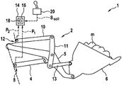
fig. 1 shows a lifting device according to the invention with a control unit and the methods stored therein for the embodiment according to an exemplary embodiment in a side view, and
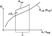
fig. 2 shows a load pressure profile of the lifting device according to fig. 1.
Detailed Description
According to fig. 1, a mobile working machine 1 has a lifting device 2 with a first hydraulic cylinder or boom cylinder 4, to which a boom 5 is articulated. At the cantilever 5A load receiver 6 configured as a bucket is arranged in an articulated manner. A load m is accommodated in the bucket 6. Furthermore, the lifting device 2 has a tipping cylinder 10, from which the bucket 6 is articulated by means of a tipping rod device 11, 13 for tipping. The tilting lever 11 is rotatably mounted on the cantilever 5. Each cylinder 4, 10 has an associated pressure sensor 8, 12, by means of which the respective piston contact pressure (bodendrack) or the load pressure of the cylinder 4, 10 can be detected. The sensors 8, 12 are connected to a control unit 14 by signal lines. In this case, the sensor 8 transmits the load pressure p of the respective hydraulic cylinder 4, 101And said sensor 12 delivers the load pressure p of the corresponding hydraulic cylinder2。
An evaluation device 16 with a method 18 stored therein for the purpose of implementation is provided in the control unit 14 for evaluating the load m. Furthermore, a control lever 20 is connected to the control unit 14 in a signaling manner, by means of which a stroke request s can be setsollTo the control unit 14. The kinematics of the lifting device 2, at least from the hydraulic cylinders 4, 10, via the boom 5, the dump lever arrangement 11, 13 up to the bucket 6, including the necessary kinematic parameters, are stored in the control unit 14.
According to the previous general description, the estimation means 16 consists of the reported load pressure p1、p2To find an estimate for the position of the bucket 6. This estimated position is passed into the method for determining the load m. In this case, the position is estimated in the exemplary embodiment shown by a detected load pressure p1istAnd a reference load pressure p1refAnd/or a slope comparison. For this purpose, the standardized stroke s of the boom cylinder 4 according to fig. 2 is used1/ssollIs analyzed. Using the estimation device 16 and the estimation method 18 stored therein, complex detection of the cylinder rod orientation in terms of installation technology can be dispensed with, and the accommodated load m can be used solely by means of the simple and robust method in terms of installation technologyThe pressure sensors 8 and 12.
A hydrostatic lifting device is disclosed, having at least one hydrostatic actuator for lifting a received load, having an associated pressure sensor for detecting a load pressure of the actuator, and having a control unit, which is signal-connected to the pressure sensor and by means of which, for determining the received load, an orientation or position of the lifting device can be estimated at least from the detected load pressure.
Furthermore, a mobile work machine with the lifting device and a method for determining or estimating the accommodated load are disclosed, which can be stored or stored for the purposes of implementation, in particular, in the control unit.
Claims (15)
1. Hydrostatic lifting device for a mobile working machine (1), comprising at least one actuator (4, 10), in particular a hydraulic cylinder, with which a load receiver (6) is associated according to a stroke requirement(s)soll) Hinging; and at least one pressure detection unit (8, 12) by means of which the respective load pressure (p) of the associated actuator (4, 10) can be detected1、p2) (ii) a And having a control unit (14) by means of which at least one load pressure (p) of the lifting device (2) can be determined1、p2) And a position or orientation to find the contained load (m), characterized by estimation means (16) by means of which the position can be estimated.
2. A lifting device according to claim 1, wherein said position can be determined by said estimating means (16) from said load pressure (p)1) According to said travel requirement(s)soll) Detected change curve (P)1ist) To estimate.
3. According to claim 1 orThe lifting device of person 2, wherein the position can be determined by the estimating device (16) from the load pressure (p)1) According to said travel requirement(s)soll) At the reference load (m)ref) Reference profile (p) detected in the case of1ref) To estimate.
4. A lifting device according to claims 2 and 3, wherein the estimation means (16) have the variation curve (p)1ist) With the reference curve (p)1ref) By which the position can be estimated.
5. A lifting device according to claim 4, wherein said first comparison operation is said variation profile (P)1ist、p1ref) Slope comparison or shape comparison.
6. Lifting device according to at least claims 2 and 3, wherein the estimation means have the variation curve (p)1ist) With the reference curve (p)1ref) By which the accommodated load (m) can be estimated.
7. A lifting device according to claim 6, wherein said second comparison operation has or is said profile (P)1ist、P1ref) Difference or offset (Δ p)1)。
8. Lifting device according to at least claims 2 and 3, wherein the profile (p)1ist) And/or the reference profile (p)1ref) According to the stroke (s, s)1) And/or the travel requirement(s)soll) But is stored in the control unit (14).
9. According to at least claims 2 and3, wherein the profile (p)1ist) And/or reference curve (p)1ref) By means of said stroke requirement(s)soll) Is stored in the control unit (14) independently of time.
10. A lifting device according to any of the preceding claims, wherein in particular the stroke(s) of the (4) of at least one of the actuators1) To normalize to the travel requirement(s)soll) The above can be stored or stored in the control unit (14).
11. Mobile working machine with a lifting device (2) designed according to one of claims 1 to 10.
12. Method for determining the accommodated load (m) of a lifting device (2) constructed according to at least one of claims 1 to 10, having the steps: "depending on said position and said at least one load pressure (p)1、p2) To find said contained load (m), characterized by the step "estimation of said position".
13. Method according to claim 12, wherein said step "estimation of said position" is based on said at least one load pressure (p)1、p2) According to said travel requirement(s)soll) Detected change curve (P)1ist) And/or according to the load pressure (p)1) According to said travel requirement(s)soll) At the reference load (m)ref) Reference profile (P) detected in the case of1ref) To be implemented.
14. Method according to claim 13, wherein said step "estimation of said position" has a step "of said variation curve (p)1ist) With the reference curve (p)1ref) Is/are as followsA first comparison ".
15. Method according to any one of claims 13 to 14, wherein said step "is based on said position and said at least one load pressure (p)1、p2) To determine the received load (m) has the step of1ist) With the reference curve (p)1ref) Second comparison of ".
Applications Claiming Priority (3)
| Application Number | Priority Date | Filing Date | Title |
|---|---|---|---|
| DE102019207953.9 | 2019-05-29 | ||
| DE102019207953.9A DE102019207953A1 (en) | 2019-05-29 | 2019-05-29 | Hydrostatic hoist, mobile work machine with it, and method for determining the load on the hoist |
| PCT/EP2020/064045 WO2020239567A1 (en) | 2019-05-29 | 2020-05-20 | Hydrostatic lifting unit, mobile working machine therewith, and method for load determination on the lifting unit |
Publications (1)
| Publication Number | Publication Date |
|---|---|
| CN113853463A true CN113853463A (en) | 2021-12-28 |
Family
ID=70779777
Family Applications (1)
| Application Number | Title | Priority Date | Filing Date |
|---|---|---|---|
| CN202080039500.XA Pending CN113853463A (en) | 2019-05-29 | 2020-05-20 | Hydrostatic lifting device, mobile working machine having a lifting device, and method for determining a load on a lifting device |
Country Status (4)
| Country | Link |
|---|---|
| EP (1) | EP3976889B1 (en) |
| CN (1) | CN113853463A (en) |
| DE (1) | DE102019207953A1 (en) |
| WO (1) | WO2020239567A1 (en) |
Families Citing this family (1)
| Publication number | Priority date | Publication date | Assignee | Title |
|---|---|---|---|---|
| CN113502860B (en) * | 2021-08-20 | 2022-08-16 | 东北大学秦皇岛分校 | Working device of 11-rod 2-degree-of-freedom loader |
Citations (3)
| Publication number | Priority date | Publication date | Assignee | Title |
|---|---|---|---|---|
| US20040111229A1 (en) * | 2002-12-06 | 2004-06-10 | Caterpillar Inc. | System for determining a linkage position |
| US20100161185A1 (en) * | 2008-12-23 | 2010-06-24 | Caterpillar Inc. | Method and apparatus for calculating payload weight |
| US20190145814A1 (en) * | 2016-04-29 | 2019-05-16 | INS- Europe | Method of weight determination of a load carried by a lifter of a lifting device and weighing device |
Family Cites Families (1)
| Publication number | Priority date | Publication date | Assignee | Title |
|---|---|---|---|---|
| DE102009018070A1 (en) * | 2009-04-20 | 2010-10-21 | Robert Bosch Gmbh | Mobile work machine with a position control device of a working arm and method for position control of a working arm of a mobile machine |
-
2019
- 2019-05-29 DE DE102019207953.9A patent/DE102019207953A1/en active Pending
-
2020
- 2020-05-20 CN CN202080039500.XA patent/CN113853463A/en active Pending
- 2020-05-20 EP EP20727277.4A patent/EP3976889B1/en active Active
- 2020-05-20 WO PCT/EP2020/064045 patent/WO2020239567A1/en unknown
Patent Citations (3)
| Publication number | Priority date | Publication date | Assignee | Title |
|---|---|---|---|---|
| US20040111229A1 (en) * | 2002-12-06 | 2004-06-10 | Caterpillar Inc. | System for determining a linkage position |
| US20100161185A1 (en) * | 2008-12-23 | 2010-06-24 | Caterpillar Inc. | Method and apparatus for calculating payload weight |
| US20190145814A1 (en) * | 2016-04-29 | 2019-05-16 | INS- Europe | Method of weight determination of a load carried by a lifter of a lifting device and weighing device |
Also Published As
| Publication number | Publication date |
|---|---|
| DE102019207953A1 (en) | 2020-12-03 |
| WO2020239567A1 (en) | 2020-12-03 |
| EP3976889B1 (en) | 2024-04-03 |
| EP3976889A1 (en) | 2022-04-06 |
Similar Documents
| Publication | Publication Date | Title |
|---|---|---|
| US6931772B2 (en) | Hydraulic shovel work amount detection apparatus, work amount detection method, work amount detection result display apparatus | |
| US9938692B2 (en) | Wheel loader payload measurement system linkage acceleration compensation | |
| US6552279B1 (en) | Method and apparatus configured to perform viscosity compensation for a payload measurement system | |
| CN101336345B (en) | For controlling the method for movement of vehicular member | |
| CA2125375C (en) | Tactile control for automated bucket loading | |
| US8126619B2 (en) | Weight calculation compensation | |
| CN107208405B (en) | Wheel loader and method for automatically accumulating transportation operation information of wheel loader | |
| KR101496497B1 (en) | Abnormal operation detection device | |
| US20180087240A1 (en) | Method for assisting an excavator operator with the loading of a transportation implement and assistance system | |
| US7480579B2 (en) | Method and apparatus for performing temperature compensation for a payload measurement system | |
| US20150002303A1 (en) | System to display remaining payload weight for a truck | |
| CN104736772A (en) | Work machine and work volume measurement method for work machine | |
| CN104781477A (en) | Work machine and work volume measurement method for work machine | |
| CN107923143A (en) | Work machine | |
| CN113853463A (en) | Hydrostatic lifting device, mobile working machine having a lifting device, and method for determining a load on a lifting device | |
| CN103221617B (en) | For the method for the hydraulic system of Control Engineering machinery | |
| JP2012035973A (en) | Loading amount management system and loading amount management method | |
| EP3589790B1 (en) | System and method for estimating implement load weights for a work vehicle | |
| WO2009054736A1 (en) | Weight calculation compensation | |
| CN113423898B (en) | Work machine, system, and work machine control method | |
| CN113494105A (en) | System and method for determining a position value of a load associated with an implement | |
| EP3589791A1 (en) | System and method for estimating implement load weights for a work vehicle with knowledge of operator-initiated control commands | |
| US11299869B2 (en) | Loading amount accumulation device and loading amount accumulation system | |
| CN114599839B (en) | Work machine, metering method, and system including work machine | |
| US20220145592A1 (en) | System and method for estimating the weight of a load carried by an implement of a work vehicle |
Legal Events
| Date | Code | Title | Description |
|---|---|---|---|
| PB01 | Publication | ||
| PB01 | Publication | ||
| SE01 | Entry into force of request for substantive examination | ||
| SE01 | Entry into force of request for substantive examination | ||
| WD01 | Invention patent application deemed withdrawn after publication |
Application publication date: 20211228 |
|
| WD01 | Invention patent application deemed withdrawn after publication |