CN113841400A - Video coding and decoding method and device - Google Patents
Video coding and decoding method and device Download PDFInfo
- Publication number
- CN113841400A CN113841400A CN202080018276.6A CN202080018276A CN113841400A CN 113841400 A CN113841400 A CN 113841400A CN 202080018276 A CN202080018276 A CN 202080018276A CN 113841400 A CN113841400 A CN 113841400A
- Authority
- CN
- China
- Prior art keywords
- inverse transform
- block
- transform
- residual
- data
- Prior art date
- Legal status (The legal status is an assumption and is not a legal conclusion. Google has not performed a legal analysis and makes no representation as to the accuracy of the status listed.)
- Pending
Links
Images


Classifications
-
- H—ELECTRICITY
- H04—ELECTRIC COMMUNICATION TECHNIQUE
- H04N—PICTORIAL COMMUNICATION, e.g. TELEVISION
- H04N19/00—Methods or arrangements for coding, decoding, compressing or decompressing digital video signals
- H04N19/10—Methods or arrangements for coding, decoding, compressing or decompressing digital video signals using adaptive coding
- H04N19/102—Methods or arrangements for coding, decoding, compressing or decompressing digital video signals using adaptive coding characterised by the element, parameter or selection affected or controlled by the adaptive coding
- H04N19/12—Selection from among a plurality of transforms or standards, e.g. selection between discrete cosine transform [DCT] and sub-band transform or selection between H.263 and H.264
-
- H—ELECTRICITY
- H04—ELECTRIC COMMUNICATION TECHNIQUE
- H04N—PICTORIAL COMMUNICATION, e.g. TELEVISION
- H04N19/00—Methods or arrangements for coding, decoding, compressing or decompressing digital video signals
- H04N19/10—Methods or arrangements for coding, decoding, compressing or decompressing digital video signals using adaptive coding
- H04N19/102—Methods or arrangements for coding, decoding, compressing or decompressing digital video signals using adaptive coding characterised by the element, parameter or selection affected or controlled by the adaptive coding
- H04N19/103—Selection of coding mode or of prediction mode
- H04N19/105—Selection of the reference unit for prediction within a chosen coding or prediction mode, e.g. adaptive choice of position and number of pixels used for prediction
-
- H—ELECTRICITY
- H04—ELECTRIC COMMUNICATION TECHNIQUE
- H04N—PICTORIAL COMMUNICATION, e.g. TELEVISION
- H04N19/00—Methods or arrangements for coding, decoding, compressing or decompressing digital video signals
- H04N19/10—Methods or arrangements for coding, decoding, compressing or decompressing digital video signals using adaptive coding
- H04N19/102—Methods or arrangements for coding, decoding, compressing or decompressing digital video signals using adaptive coding characterised by the element, parameter or selection affected or controlled by the adaptive coding
- H04N19/119—Adaptive subdivision aspects, e.g. subdivision of a picture into rectangular or non-rectangular coding blocks
-
- H—ELECTRICITY
- H04—ELECTRIC COMMUNICATION TECHNIQUE
- H04N—PICTORIAL COMMUNICATION, e.g. TELEVISION
- H04N19/00—Methods or arrangements for coding, decoding, compressing or decompressing digital video signals
- H04N19/10—Methods or arrangements for coding, decoding, compressing or decompressing digital video signals using adaptive coding
- H04N19/102—Methods or arrangements for coding, decoding, compressing or decompressing digital video signals using adaptive coding characterised by the element, parameter or selection affected or controlled by the adaptive coding
- H04N19/132—Sampling, masking or truncation of coding units, e.g. adaptive resampling, frame skipping, frame interpolation or high-frequency transform coefficient masking
-
- H—ELECTRICITY
- H04—ELECTRIC COMMUNICATION TECHNIQUE
- H04N—PICTORIAL COMMUNICATION, e.g. TELEVISION
- H04N19/00—Methods or arrangements for coding, decoding, compressing or decompressing digital video signals
- H04N19/10—Methods or arrangements for coding, decoding, compressing or decompressing digital video signals using adaptive coding
- H04N19/134—Methods or arrangements for coding, decoding, compressing or decompressing digital video signals using adaptive coding characterised by the element, parameter or criterion affecting or controlling the adaptive coding
- H04N19/136—Incoming video signal characteristics or properties
-
- H—ELECTRICITY
- H04—ELECTRIC COMMUNICATION TECHNIQUE
- H04N—PICTORIAL COMMUNICATION, e.g. TELEVISION
- H04N19/00—Methods or arrangements for coding, decoding, compressing or decompressing digital video signals
- H04N19/10—Methods or arrangements for coding, decoding, compressing or decompressing digital video signals using adaptive coding
- H04N19/169—Methods or arrangements for coding, decoding, compressing or decompressing digital video signals using adaptive coding characterised by the coding unit, i.e. the structural portion or semantic portion of the video signal being the object or the subject of the adaptive coding
- H04N19/17—Methods or arrangements for coding, decoding, compressing or decompressing digital video signals using adaptive coding characterised by the coding unit, i.e. the structural portion or semantic portion of the video signal being the object or the subject of the adaptive coding the unit being an image region, e.g. an object
- H04N19/176—Methods or arrangements for coding, decoding, compressing or decompressing digital video signals using adaptive coding characterised by the coding unit, i.e. the structural portion or semantic portion of the video signal being the object or the subject of the adaptive coding the unit being an image region, e.g. an object the region being a block, e.g. a macroblock
Landscapes
- Engineering & Computer Science (AREA)
- Multimedia (AREA)
- Signal Processing (AREA)
- Physics & Mathematics (AREA)
- Discrete Mathematics (AREA)
- General Physics & Mathematics (AREA)
- Compression Or Coding Systems Of Tv Signals (AREA)
Abstract
Aspects of the present disclosure provide methods and apparatuses for video encoding/decoding. In some examples, an apparatus for video decoding includes a processing circuit. The processing circuit may decode encoding information for a coefficient block from an encoded video bitstream. The coding information may indicate a size of the coefficient block. The processing circuit may determine, based on the size of the coefficient block, an order in which horizontal and vertical inverse transforms in the main inverse transform are to be performed on the transform coefficients of the coefficient block to obtain residual data of the residual block. When the size of the coefficient block satisfies the condition, a vertical inverse transform is performed after performing a horizontal inverse transform on the transform coefficients of the coefficient block. The processing circuitry may reconstruct samples in the residual block based on the residual data.
Description
Cross-referencing
The present application claims priority of "Video Coding Method and Apparatus (Method and Apparatus for Video Coding)" in us patent application 16/812,000, filed 3/6/2020, and priority of "Adaptive Transform Coefficient Zero output (Adaptive Transform Coding Zero-Out)" in us provisional application 62/816,124, filed 9/3/2019. The entire contents of these prior applications are incorporated herein by reference.
Technical Field
Embodiments are described that relate generally to video coding and decoding.
Background
The background description provided herein is intended to be a general presentation of the background of the application. Work of the presently named inventors, to the extent it is described in this background section, as well as aspects of the description, is not admitted to be prior art by inclusion in this application, nor is it expressly or implied that it is prior art to the present application.
Video encoding and decoding may be performed by an inter-picture prediction technique with motion compensation. Uncompressed digital video may comprise a series of pictures, each picture having spatial dimensions of, for example, 1920x1080 luma samples and related chroma samples. The series of pictures has a fixed or variable picture rate (also informally referred to as frame rate), e.g. 60 pictures per second or 60 Hz. Uncompressed video has very large bit rate requirements. For example, 1080p 604: 2:0 video (1920x1080 luminance sample resolution, 60Hz frame rate) with 8 bits per sample requires close to 1.5Gbit/s bandwidth. One hour of such video requires more than 600GB of storage space.
One purpose of video encoding and decoding is to reduce redundant information of an input video signal by compression. Video compression can help reduce the bandwidth or storage requirements described above, by two or more orders of magnitude in some cases. Lossless and lossy compression, as well as combinations of both, may be employed. Lossless compression refers to a technique for reconstructing an exact copy of an original signal from a compressed original signal. When lossy compression is used, the reconstructed signal may not be identical to the original signal, but the distortion between the original signal and the reconstructed signal is small enough that the reconstructed signal is useful for the intended application. Lossy compression is widely used for video. The amount of distortion tolerated depends on the application. For example, some users consuming streaming media applications may tolerate higher distortion than users of television applications. The achievable compression ratio reflects: higher allowable/tolerable distortion may result in higher compression ratios.
Video encoders and decoders may utilize several broad classes of techniques, including, for example: motion compensation, transformation, quantization and entropy coding.
Video codec techniques may include known intra-coding techniques. In intra coding, sample values are represented without reference to samples or other data of a previously reconstructed reference picture. In some video codecs, a picture is spatially subdivided into blocks of samples. When all sample blocks are encoded in intra mode, the picture may be an intra picture. Intra pictures and their derivatives (e.g., independent decoder refresh pictures) can be used to reset the decoder state and thus can be used as the first picture in an encoded video bitstream and video session, or as still images. Samples of the intra block may be used for the transform, and the transform coefficients may be quantized prior to entropy encoding. Intra prediction may be a technique that minimizes sample values in the pre-transform domain. In some cases, the smaller the transformed DC value and the smaller the AC coefficient, the fewer bits are needed to represent the block after entropy coding at a given quantization step size.
As is known from techniques such as MPEG-2 generation coding, conventional intra-frame coding does not use intra-prediction. However, some newer video compression techniques include: techniques are attempted to derive data chunks from, for example, surrounding sample data and/or metadata obtained during spatially adjacent encoding/decoding and prior to the decoding order. This technique was later referred to as an "intra-prediction" technique. It is noted that, at least in some cases, intra prediction uses only the reference data of the current picture being reconstructed, and not the reference data of the reference picture.
There may be many different forms of intra prediction. When more than one such technique may be used in a given video coding technique, the technique used may be coded in an intra-prediction mode. In some cases, a mode may have sub-modes and/or parameters, and these modes may be encoded separately or included in a mode codeword. Which codeword is used for a given mode/sub-mode/parameter combination affects the coding efficiency gain through intra prediction, and so does the entropy coding technique used to convert the codeword into a bitstream.
H.264 introduces an intra prediction mode that improves in h.265 and further improves in newer coding techniques such as what is known as Joint Exploration Model (JEM)/next generation video coding (VVC)/reference set (BMS). A prediction block may be formed by using neighboring sample values belonging to already available samples. In some examples, sample values of neighboring samples are copied into a prediction block in a certain direction. The reference to the direction used may be encoded in the bitstream or may itself be predicted.
Referring to fig. 1A, the bottom right depicts a subset of nine prediction directions known from the 33 possible prediction directions of h.265 (33 angular modes corresponding to 35 intra modes). The point (101) where the arrows converge represents the sample being predicted. The arrows indicate the direction in which the samples are being predicted. For example, arrow (102) represents the prediction of a sample (101) from one or more samples at an angle of 45 degrees to the horizontal from the upper right. Similarly, arrow (103) represents the prediction of a sample (101) from one or more samples at an angle of 22.5 degrees to the horizontal at the bottom left.
Still referring to fig. 1A, a square block (104) comprising 4x4 samples is shown at the top left (indicated by the thick dashed line). The square block (104) includes 16 samples, each labeled with "S", and its position in the Y dimension (e.g., row index) and its position in the X dimension (e.g., column index). For example, sample S21 is the second sample in the Y dimension (starting from the top) and the first sample in the X dimension (starting from the left). Similarly, sample S44 is the fourth sample in the block (104) in both the X and Y dimensions. Since the block is a 4 × 4 sample size, S44 is located at the lower right corner. Reference samples following a similar numbering scheme are also shown. The reference sample is labeled with "R" and its Y position (e.g., row index) and X position (e.g., column index) relative to the block (104). In h.264 and h.265, the prediction samples are adjacent to the block being reconstructed, so negative values need not be used.
Intra picture prediction can be performed by copying the reference sample values from the neighbouring samples occupied by the signaled prediction direction. For example, assume that the encoded video bitstream includes signaling indicating, for the block, a prediction direction that coincides with the arrow (102), i.e. samples are predicted from one or more predicted samples whose upper right is at a 45 degree angle to the horizontal direction. In this case, samples S41, S32, S23, and S14 are predicted from the same reference sample R05. From the reference sample R08, a sample S44 is predicted.
In some cases, the values of multiple reference samples may be combined, for example by interpolation, to compute the reference sample, especially when the direction cannot be divided exactly by 45 degrees.
As video coding techniques have evolved, the number of possible directions has increased. In h.264 (2003), nine different directions can be represented. There are 33 increases in H.265 (2013) and JEM/VVC/BMS, and up to 65 orientations can be supported at the time of this application. Experiments have been performed to identify the most likely directions and some techniques in entropy coding are used to represent those possible directions using a small number of bits, accepting some cost for less likely directions. Furthermore, sometimes the direction itself can be predicted from the neighboring directions used in neighboring, already decoded blocks.
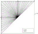
Fig. 1B shows a schematic diagram (180) for depicting 65 intra prediction directions according to JEM to show the increasing number of prediction directions over time.
The mapping of intra prediction direction bits in the coded video bitstream representing directions may differ from one video coding technique to another and may for example range from a simple direct mapping of intra prediction modes to prediction directions of codewords to a complex adaptation scheme including most probable modes and similar techniques. In all cases, however, there may be certain directions in the video content that are statistically less likely to occur than other directions. Since the goal of video compression is to reduce redundancy, in well-functioning video coding techniques, those unlikely directions will be represented using a greater number of bits than the more likely directions.
Video encoding and decoding may be performed by an inter-picture prediction technique with motion compensation. Motion compensation may be a lossy compression technique and may involve the following: a specimen data block from a previously reconstructed picture or a portion of a reconstructed picture (reference picture) is spatially shifted in the direction indicated by a motion vector (hereinafter referred to as MV) for prediction of the newly reconstructed picture or portion of the picture. In some cases, the reference picture may be the same as the picture currently being reconstructed. The MV may have two dimensions X and Y, or three dimensions, where the third dimension represents the reference picture in use (the latter may be indirectly the temporal dimension).
In some video compression techniques, an MV applied to a certain sample data region may be predicted from other MVs, e.g., from those MVs that are related to another sample data region spatially adjacent to the region being reconstructed and that precede the MV in decoding order. This can greatly reduce the amount of data required to encode the MV, thereby eliminating redundant information and increasing the amount of compression. MV prediction can be performed efficiently, for example, when encoding an input video signal derived from a camera (referred to as natural video), there is a statistical possibility that regions having areas larger than the applicable region of a single MV will move in similar directions, and thus prediction can be performed using similar motion vectors derived from MVs of neighboring regions in some cases. This results in the MVs found for a given region being similar or identical to the MVs predicted from the surrounding MVs and, after entropy encoding, can in turn be represented by a smaller number of bits than the number of bits used when directly encoding the MVs. In some cases, MV prediction may be an example of lossless compression of a signal (i.e., MV) derived from an original signal (i.e., a sample stream). In other cases, MV prediction itself may be lossy, for example due to rounding errors that occur when calculating the predicted values from several surrounding MVs.
h.265/HEVC (ITU-T rec.h.265, "high efficiency video coding", month 2016) describes various MV prediction mechanisms. Among the various MV prediction mechanisms provided by h.265, described herein is a technique referred to hereinafter as "spatial merging".
Referring to fig. 2, a current block (201) includes samples found by an encoder during a motion search, which can be predicted from a previous block spatially shifted by the same size. The MV is not directly encoded but is derived from metadata associated with one or more reference pictures, e.g. from the nearest (in decoding order) reference picture, by using the MV associated with any of the five surrounding samples. Of these, five surrounding samples are represented by a0, a1, and B0, B1, B2(202 to 206), respectively. In h.265, MV prediction can use the prediction value of the same reference picture that neighboring blocks are using.
Disclosure of Invention
Aspects of the present disclosure provide methods and apparatuses for video encoding/decoding. In some examples, an apparatus for video decoding includes a processing circuit. The processing circuit may decode encoding information for a coefficient block from an encoded video bitstream, the encoding information indicating a size of the coefficient block. The processing circuitry may determine, based on the size of the coefficient block, an order in which to perform a horizontal inverse transform and a vertical inverse transform in a main inverse transform on transform coefficients of the coefficient block to obtain residual data for a residual block. When the size of the coefficient block satisfies a condition, performing the vertical inverse transform after performing the horizontal inverse transform on the transform coefficients of the coefficient block. The processing circuitry may reconstruct samples in the residual block based on the residual data. In an example, the condition is that the size of the coefficient block is 32 × 64. In an example, the condition is that the height N of the M × N coefficient block is greater than the width M of the coefficient block. In an example, the size of the coefficient block is M × N, M and N being positive integers; first residual data within an mxn region in the residual block will be calculated by the main inverse transform and second residual data outside the mxn region in the residual block will not be calculated by the main inverse transform, M being less than or equal to M and N being less than or equal to N; and the condition is that the ratio M/M is greater than or equal to the ratio N/N.
Aspects of the present disclosure provide methods and apparatuses for video encoding/decoding. In some examples, an apparatus for video decoding includes a processing circuit. The processing circuit decodes coding information for a coefficient block, the coefficient block being from an encoded video bitstream, the coding information indicating a size of the coefficient block. The processing circuit determines whether to reduce the number of calculations of one of a horizontal inverse transform and a vertical inverse transform in a main inverse transform based on the size of the coefficient block, the vertical inverse transform transforming transform coefficients of the coefficient block into intermediate data of an intermediate block, the horizontal inverse transform transforming the intermediate data into residual data in a residual block. The processing circuitry may perform the main inverse transform. When it is determined that the number of calculations in the vertically inverse transform is to be reduced, calculating the intermediate data of the top 16 rows in the intermediate block by the vertically inverse transform, and the remaining intermediate data in the intermediate block is zero; and when it is determined that the number of calculations in the horizontal inverse transform is to be reduced, the residual data of the left 16 columns in the residual block is calculated by the horizontal inverse transform, and the remaining residual data in the residual block is zero. The processing circuitry may reconstruct samples in the residual block based on the residual data.
In an embodiment, the size of the coefficient block is 32 × 64. One of the horizontal inverse transform and the vertical inverse transform is a vertical inverse transform. When the size of the coefficient block is 32 × 64, the processing circuit may determine to reduce the number of computations in the vertical inverse transform. The processing circuitry may perform a main inverse transform, wherein the middle data of the top 16 rows in the middle block may be calculated by the vertical inverse transform and the remaining middle data in the middle block is zero.
In an embodiment, the size of the coefficient block is 32 × 64. One of the horizontal inverse transform and the vertical inverse transform is a horizontal inverse transform. Determining to reduce the number of computations in the horizontal inverse transform when the size of the coefficient block is 32 × 64; and performing the main inverse transform, wherein the left 16 columns of residual data in the residual block are calculated by the horizontal inverse transform, and the remaining residual data in the residual block is zero.
In an embodiment, the size of the coefficient block is 32 × 32. One of the horizontal inverse transform and the vertical inverse transform is a horizontal inverse transform. Determining to reduce the number of computations in the horizontal inverse transform when the size of the coefficient block is 32x 32; and performing the main inverse transform, wherein the left 16 columns of residual data in the residual block are calculated by the horizontal inverse transform, the remaining residual data in the residual block are zero, and the middle data in the middle block is calculated by the vertical inverse transform.
In an embodiment, the size of the coefficient block is 32 × 32. One of the horizontal inverse transform and the vertical inverse transform is a vertical inverse transform. Determining to reduce the number of computations in the inverse vertical transform when the size of the coefficient block is 32x 32; and performing the main inverse transform, wherein the middle data of the top 16 rows in the middle block is calculated by the vertical inverse transform, the remaining middle data in the middle block is zero, and the residual data in the residual block is calculated by the horizontal inverse transform.
Drawings
Other features, properties, and various advantages of the disclosed subject matter will be more apparent from the following detailed description and the accompanying drawings, in which:
fig. 1A is a schematic diagram of an exemplary subset of intra prediction modes.
Fig. 1B is a diagram of exemplary intra prediction directions.
Fig. 2 is a schematic diagram of a current block and its surrounding spatial merge candidates in one example.
Fig. 3 is a schematic diagram of a simplified block diagram of a communication system according to an embodiment.
Fig. 4 is a schematic diagram of a simplified block diagram of a communication system according to an embodiment.
Fig. 5 is a schematic diagram of a simplified block diagram of a decoder according to an embodiment.
Fig. 6 is a schematic diagram of a simplified block diagram of an encoder according to an embodiment.
Fig. 7 shows a block diagram of an encoder according to another embodiment.
Fig. 8 shows a block diagram of a decoder according to another embodiment.
Fig. 9 shows an example of a transform unit syntax according to an embodiment.
Fig. 10A to 10C illustrate examples of residual coding syntax according to an embodiment.
Fig. 11A to 11B illustrate an example of a main transform according to an embodiment.
Fig. 12A-12E illustrate an exemplary transformation process according to an embodiment.
Fig. 13 shows an example of a residual codec syntax according to another embodiment.
Fig. 14 shows a flowchart outlining a method according to an embodiment.
Fig. 15 shows a flowchart outlining a method according to an embodiment.
Fig. 16 is a schematic diagram of a computer system, according to an embodiment.
Detailed Description
Fig. 3 is a simplified block diagram of a communication system (300) according to an embodiment disclosed herein. The communication system (300) includes a plurality of terminal devices that can communicate with each other through, for example, a network (350). For example, a communication system (300) includes a first pair of end devices (310) and (320) interconnected by a network (350). In the embodiment of fig. 3, the first pair of terminal devices (310) and (320) performs unidirectional data transmission. For example, a terminal device (310) may encode video data, such as a video picture stream captured by the terminal device (310), for transmission over a network (350) to another terminal device (320). The encoded video data is transmitted in the form of one or more encoded video streams. The terminal device (320) may receive encoded video data from the network (350), decode the encoded video data to recover the video data, and display a video picture according to the recovered video data. Unidirectional data transmission is common in applications such as media services.
In another embodiment, the communication system (300) includes a second pair of terminal devices (330) and (340) that perform bi-directional transmission of encoded video data, which may occur, for example, during a video conference. For bi-directional data transmission, each of the end devices (330) and (340) may encode video data (e.g., a stream of video pictures captured by the end device) for transmission over the network (350) to the other of the end devices (330) and (340). Each of terminal devices (330) and (340) may also receive encoded video data transmitted by the other of terminal device (330) and terminal device (340), and may decode the encoded video data to recover the video data, and may display video pictures on an accessible display device according to the recovered video data.
In the embodiment of fig. 2, the terminal devices (310), (320), (330), and (340) may be a server, a personal computer, and a smartphone, but the principles disclosed herein may not be limited thereto. Embodiments disclosed herein are applicable to laptop computers, tablet computers, media players, and/or dedicated video conferencing equipment. Network (350) represents any number of networks that transport encoded video data between end devices (310), (320), (330), and (340), including, for example, wired (wired) and/or wireless communication networks. The communication network (350) may exchange data in circuit-switched and/or packet-switched channels. The network may include a telecommunications network, a local area network, a wide area network, and/or the internet. For purposes of this application, the architecture and topology of the network (350) may be immaterial to the operation disclosed herein, unless explained below.
By way of example, fig. 4 illustrates the placement of a video encoder and a video decoder in a streaming environment. The subject matter disclosed herein is equally applicable to other video-enabled applications including, for example, video conferencing, digital TV, storing compressed video on digital media including CDs, DVDs, memory sticks, and the like.
The streaming system may include an acquisition subsystem (413), which may include a video source (401), such as a digital camera, that creates an uncompressed video picture stream (402). In an embodiment, the video picture stream (402) includes samples taken by a digital camera. The video picture stream (402) is depicted as a thick line to emphasize a high data amount video picture stream compared to the encoded video data (404) (or the encoded video bitstream), the video picture stream (402) being processable by an electronic device (420), the electronic device (420) comprising a video encoder (403) coupled to a video source (401). The video encoder (403) may comprise hardware, software, or a combination of hardware and software to implement or embody aspects of the disclosed subject matter as described in more detail below. The encoded video data (404) (or encoded video codestream (404)) is depicted as a thin line to emphasize the lower data amount of the encoded video data (404) (or encoded video codestream (404)) as compared to the video picture stream (402), which may be stored on a streaming server (405) for future use. One or more streaming client subsystems, such as client subsystem (406) and client subsystem (408) in fig. 4, may access a streaming server (405) to retrieve copies (407) and copies (409) of encoded video data (404). The client subsystem (406) may include, for example, a video decoder (410) in an electronic device (430). The video decoder (410) decodes incoming copies (407) of the encoded video data and generates an output video picture stream (411) that may be presented on a display (412), such as a display screen, or another presentation device (not depicted). In some streaming systems, encoded video data (404), video data (407), and video data (409) (e.g., video streams) may be encoded according to certain video encoding/compression standards. Examples of such standards include ITU-T H.265. In an embodiment, the Video Coding standard under development is informally referred to as next generation Video Coding (VVC), and the present application may be used in the context of the VVC standard.
It should be noted that electronic device (420) and electronic device (430) may include other components (not shown). For example, electronic device (420) may include a video decoder (not shown), and electronic device (430) may also include a video encoder (not shown).
Fig. 5 is a block diagram of a video decoder (510) according to an embodiment of the present disclosure. The video decoder (510) may be disposed in an electronic device (530). The electronic device (530) may include a receiver (531) (e.g., a receive circuit). The video decoder (510) may be used in place of the video decoder (410) in the fig. 4 embodiment.
The receiver (531) may receive one or more encoded video sequences to be decoded by the video decoder (510); in the same or another embodiment, the encoded video sequences are received one at a time, wherein each encoded video sequence is decoded independently of the other encoded video sequences. The encoded video sequence may be received from a channel (501), which may be a hardware/software link to a storage device that stores encoded video data. The receiver (531) may receive encoded video data as well as other data, e.g. encoded audio data and/or auxiliary data streams, which may be forwarded to their respective usage entities (not indicated). The receiver (531) may separate the encoded video sequence from other data. To prevent network jitter, a buffer memory (515) may be coupled between the receiver (531) and the entropy decoder/parser (520) (hereinafter "parser (520)"). In some applications, the buffer memory (515) is part of the video decoder (510). In other cases, the buffer memory (515) may be disposed external (not labeled) to the video decoder (510). While in other cases a buffer memory (not labeled) is provided external to the video decoder (510), e.g., to prevent network jitter, and another buffer memory (515) may be configured internal to the video decoder (510), e.g., to handle playout timing. The buffer memory (515) may not be required to be configured or may be made smaller when the receiver (531) receives data from a store/forward device with sufficient bandwidth and controllability or from an isochronous network. Of course, for use over traffic packet networks such as the internet, a buffer memory (515) may also be required, which may be relatively large and may be of adaptive size, and may be implemented at least partially in an operating system or similar element (not labeled) external to the video decoder (510).
The video decoder (510) may include a parser (520) to reconstruct symbols (521) from the encoded video sequence. The categories of these symbols include information for managing the operation of the video decoder (510), as well as potential information to control a display device, such as a display screen (512), that is not an integral part of the electronic device (530), but may be coupled to the electronic device (530), as shown in fig. 5. The control Information for the display device may be a parameter set fragment (not shown) of Supplemental Enhancement Information (SEI message) or Video Usability Information (VUI). The parser (520) may parse/entropy decode the received encoded video sequence. Encoding of the encoded video sequence may be performed in accordance with video coding techniques or standards and may follow various principles, including variable length coding, Huffman coding, arithmetic coding with or without contextual sensitivity, and so forth. A parser (520) may extract a subgroup parameter set for at least one of the subgroups of pixels in the video decoder from the encoded video sequence based on at least one parameter corresponding to the group. A subgroup may include a Group of Pictures (GOP), a picture, a tile, a slice, a macroblock, a Coding Unit (CU), a block, a Transform Unit (TU), a Prediction Unit (PU), and so on. The parser (520) may also extract information from the encoded video sequence, such as transform coefficients, quantizer parameter values, motion vectors, and so on.
The parser (520) may perform entropy decoding/parsing operations on the video sequence received from the buffer memory (515) to create symbols (521).
The reconstruction of the symbol (521) may involve a number of different units depending on the type of the encoded video picture or portion of the encoded video picture (e.g., inter and intra pictures, inter and intra blocks), among other factors. Which units are involved and the way they are involved can be controlled by subgroup control information parsed from the coded video sequence by a parser (520). For the sake of brevity, such a subgroup control information flow between parser (520) and the following units is not described.
In addition to the functional blocks already mentioned, the video decoder (510) may be conceptually subdivided into several functional units as described below. In a practical embodiment operating under business constraints, many of these units interact closely with each other and may be integrated with each other. However, for the purposes of describing the disclosed subject matter, a conceptual subdivision into the following functional units is appropriate.
The first unit is a scaler/inverse transform unit (551). The scaler/inverse transform unit (551) receives the quantized transform coefficients as symbols (521) from the parser (520) along with control information including which transform scheme to use, block size, quantization factor, quantization scaling matrix, etc. The sealer/inverse transform unit (551) may output a block comprising sample values, which may be input into an aggregator (555).
In some cases, the output samples of sealer/inverse transform unit (551) may belong to an intra-coded block; namely: predictive information from previously reconstructed pictures is not used, but blocks of predictive information from previously reconstructed portions of the current picture may be used. Such predictive information may be provided by an intra picture prediction unit (552). In some cases, the intra picture prediction unit (552) generates surrounding blocks of the same size and shape as the block being reconstructed using the reconstructed information extracted from the current picture buffer (558). For example, the current picture buffer (558) buffers a partially reconstructed current picture and/or a fully reconstructed current picture. In some cases, the aggregator (555) adds the prediction information generated by the intra prediction unit (552) to the output sample information provided by the scaler/inverse transform unit (551) on a per sample basis.
In other cases, the output samples of sealer/inverse transform unit (551) may belong to inter-coded and potential motion compensated blocks. In this case, the motion compensated prediction unit (553) may access a reference picture memory (557) to fetch samples for prediction. After motion compensating the extracted samples according to the sign (521), the samples may be added to the output of the scaler/inverse transform unit (551), in this case referred to as residual samples or residual signals, by an aggregator (555), thereby generating output sample information. The motion compensated prediction unit (553) fetching prediction samples from an address within the reference picture memory (557) may be motion vector controlled and used by the motion compensated prediction unit (553) in the form of the symbol (521), the symbol (521) comprising, for example, X, Y and a reference picture component. Motion compensation may also include interpolation of sample values fetched from a reference picture memory (557), motion vector prediction mechanisms, etc., when using sub-sample exact motion vectors.
The output samples of the aggregator (555) may be employed by various loop filtering techniques in the loop filter unit (556). The video compression techniques may include in-loop filter techniques that are controlled by parameters included in the encoded video sequence (also referred to as an encoded video bitstream) and that are available to the loop filter unit (556) as symbols (521) from the parser (520). However, in other embodiments, the video compression techniques may also be responsive to meta-information obtained during decoding of previous (in decoding order) portions of the encoded picture or encoded video sequence, as well as to sample values previously reconstructed and loop filtered.
The output of the loop filter unit (556) may be a sample stream that may be output to a display device (512) and stored in a reference picture memory (557) for subsequent inter picture prediction.
Once fully reconstructed, some of the coded pictures may be used as reference pictures for future prediction. For example, once the encoded picture corresponding to the current picture is fully reconstructed and the encoded picture is identified (by, e.g., parser (520)) as a reference picture, current picture buffer (558) may become part of reference picture memory (557) and a new current picture buffer may be reallocated before starting reconstruction of a subsequent encoded picture.
The video decoder (510) may perform decoding operations according to predetermined video compression techniques, such as in the ITU-T h.265 standard. The encoded video sequence may conform to the syntax specified by the video compression technique or standard used, in the sense that the encoded video sequence conforms to the syntax of the video compression technique or standard and the configuration files recorded in the video compression technique or standard. In particular, the configuration file may select certain tools from all tools available in the video compression technology or standard as the only tools available under the configuration file. For compliance, the complexity of the encoded video sequence is also required to be within the limits defined by the level of the video compression technique or standard. In some cases, the hierarchy limits the maximum picture size, the maximum frame rate, the maximum reconstruction sampling rate (measured in units of, e.g., mega samples per second), the maximum reference picture size, and so on. In some cases, the limits set by the hierarchy may be further defined by a Hypothetical Reference Decoder (HRD) specification and metadata signaled HRD buffer management in the encoded video sequence.
In an embodiment, the receiver (531) may receive additional (redundant) data along with the encoded video. The additional data may be part of an encoded video sequence. The additional data may be used by the video decoder (510) to properly decode the data and/or more accurately reconstruct the original video data. The additional data may be in the form of, for example, a temporal, spatial, or signal-to-noise ratio (SNR) enhancement layer, a redundant slice, a redundant picture, a forward error correction code, and so forth.
Fig. 6 is a block diagram of a video encoder (603) according to an embodiment of the disclosure. The video encoder (603) is disposed in an electronic device (620). The electronic device (620) includes a transmitter (640) (e.g., a transmission circuit). The video encoder (603) may be used in place of the video encoder (403) in the fig. 4 embodiment.
Video encoder (603) may receive video samples from a video source (601) (not part of electronics (620) in the fig. 6 embodiment) that may capture video images to be encoded by video encoder (603). In another embodiment, the video source (601) is part of the electronic device (620).
The video source (601) may provide a source video sequence in the form of a stream of digital video samples to be encoded by the video encoder (603), which may have any suitable bit depth (e.g., 8-bit, 10-bit, 12-bit … …), any color space (e.g., bt.601y CrCB, RGB … …), and any suitable sampling structure (e.g., Y CrCB 4:2:0, Y CrCB 4:4: 4). In the media service system, the video source (601) may be a storage device that stores previously prepared video. In a video conferencing system, the video source (601) may be a camera that captures local image information as a video sequence. Video data may be provided as a plurality of individual pictures that are given motion when viewed in sequence. The picture itself may be constructed as an array of spatial pixels, where each pixel may comprise one or more samples, depending on the sampling structure, color space, etc. used. The relationship between pixels and samples can be readily understood by those skilled in the art. The following text focuses on describing the samples.
According to an embodiment, the video encoder (603) may encode and compress pictures of a source video sequence into an encoded video sequence (643) in real-time or under any other temporal constraint required by an application. It is a function of the controller (650) to implement the appropriate encoding speed. In some embodiments, the controller (650) controls and is functionally coupled to other functional units as described below. For simplicity, the couplings are not labeled in the figures. The parameters set by the controller (650) may include rate control related parameters (picture skip, quantizer, lambda value of rate distortion optimization technique, etc.), picture size, group of pictures (GOP) layout, maximum motion vector search range, etc. The controller (650) may be used to have other suitable functions relating to the video encoder (603) optimized for a certain system design.
In some embodiments, the video encoder (603) operates in an encoding loop. As a brief description, in an embodiment, an encoding loop may include a source encoder (630) (e.g., responsible for creating symbols, e.g., a stream of symbols, based on input pictures and reference pictures to be encoded) and a (local) decoder (633) embedded in a video encoder (603). The decoder (633) reconstructs the symbols to create sample data in a similar manner as a (remote) decoder creates sample data (since in the video compression techniques considered herein any compression between the symbols and the encoded video bitstream is lossless). The reconstructed sample stream (sample data) is input to a reference picture memory (634). Since the decoding of the symbol stream produces bit accurate results independent of decoder location (local or remote), the content in the reference picture store (634) also corresponds bit accurately between the local encoder and the remote encoder. In other words, the reference picture samples that the prediction portion of the encoder "sees" are identical to the sample values that the decoder would "see" when using prediction during decoding. This reference picture synchronization philosophy (and the drift that occurs if synchronization cannot be maintained due to, for example, channel errors) is also used in some related techniques.
The operation of the "local" decoder (633) may be the same as a "remote" decoder, such as the video decoder (510) described in detail above in connection with fig. 5. However, referring briefly to fig. 5 additionally, when symbols are available and the entropy encoder (645) and parser (520) are able to losslessly encode/decode the symbols into an encoded video sequence, the entropy decoding portion of the video decoder (510), including the buffer memory (515) and parser (520), may not be fully implemented in the local decoder (633).
At this point it can be observed that any decoder technique other than the parsing/entropy decoding present in the decoder must also be present in the corresponding encoder in substantially the same functional form. For this reason, the present application focuses on decoder operation. The description of the encoder techniques may be simplified because the encoder techniques are reciprocal to the fully described decoder techniques. A more detailed description is only needed in certain areas and is provided below.
During operation, in some embodiments, the source encoder (630) may perform motion compensated predictive coding. The motion compensated predictive coding predictively codes an input picture with reference to one or more previously coded pictures from the video sequence that are designated as "reference pictures". In this way, an encoding engine (632) encodes differences between pixel blocks of an input picture and pixel blocks of a reference picture, which may be selected as a prediction reference for the input picture.
The local video decoder (633) may decode encoded video data for a picture that may be designated as a reference picture based on the symbols created by the source encoder (630). The operation of the encoding engine (632) may be a lossy process. When the encoded video data can be decoded at a video decoder (not shown in fig. 6), the reconstructed video sequence may typically be a copy of the source video sequence with some errors. The local video decoder (633) replicates a decoding process that may be performed on reference pictures by the video decoder, and may cause reconstructed reference pictures to be stored in a reference picture cache (634). In this way, the video encoder (603) may locally store a copy of the reconstructed reference picture that has common content (no transmission errors) with the reconstructed reference picture to be obtained by the remote video decoder.
Predictor (635) may perform a prediction search for coding engine (632). That is, for a new picture to be encoded, predictor (635) may search reference picture memory (634) for sample data (as candidate reference pixel blocks) or some metadata, such as reference picture motion vectors, block shapes, etc., that may be referenced as appropriate predictions for the new picture. The predictor (635) may operate on a block-by-block basis of samples to find a suitable prediction reference. In some cases, from search results obtained by predictor (635), it may be determined that the input picture may have prediction references derived from multiple reference pictures stored in reference picture memory (634).
The controller (650) may manage the encoding operations of the source encoder (630), including, for example, setting parameters and subgroup parameters for encoding the video data.
The outputs of all of the above functional units may be entropy encoded in an entropy encoder (645). The entropy encoder (645) losslessly compresses the symbols generated by the various functional units according to techniques such as huffman coding, variable length coding, arithmetic coding, etc., to convert the symbols into an encoded video sequence.
The transmitter (640) may buffer the encoded video sequence created by the entropy encoder (645) in preparation for transmission over a communication channel (660), which may be a hardware/software link to a storage device that will store the encoded video data. The transmitter (640) may combine the encoded video data from the video encoder (603) with other data to be transmitted, such as encoded audio data and/or an auxiliary data stream (sources not shown).
The controller (650) may manage the operation of the video encoder (603). During encoding, the controller (650) may assign a certain encoded picture type to each encoded picture, but this may affect the encoding techniques applicable to the respective picture. For example, pictures may be generally assigned to any of the following picture types:
intra pictures (I pictures), which may be pictures that can be encoded and decoded without using any other picture in the sequence as a prediction source. Some video codecs tolerate different types of intra pictures, including, for example, Independent Decoder Refresh ("IDR") pictures. Those skilled in the art are aware of variants of picture I and their corresponding applications and features.
Predictive pictures (P pictures), which may be pictures that may be encoded and decoded using intra prediction or inter prediction that uses at most one motion vector and reference index to predict sample values of each block.
Bi-predictive pictures (B-pictures), which may be pictures that can be encoded and decoded using intra-prediction or inter-prediction that uses at most two motion vectors and reference indices to predict sample values of each block. Similarly, multiple predictive pictures may use more than two reference pictures and associated metadata for reconstructing a single block.
A source picture may typically be spatially subdivided into blocks of samples (e.g., blocks of 4x4, 8x8, 4x 8, or 16x16 samples) and encoded block-wise. These blocks may be predictively encoded with reference to other (encoded) blocks that are determined according to the encoding allocation applied to their respective pictures. For example, a block of an I picture may be non-predictive encoded, or the block may be predictive encoded (spatial prediction or intra prediction) with reference to an already encoded block of the same picture. The pixel block of the P picture can be prediction-coded by spatial prediction or by temporal prediction with reference to one previously coded reference picture. A block of a B picture may be prediction coded by spatial prediction or by temporal prediction with reference to one or two previously coded reference pictures.
The video encoder (603) may perform encoding operations according to a predetermined video encoding technique or standard, such as the ITU-T h.265 recommendation. In operation, the video encoder (603) may perform various compression operations, including predictive encoding operations that exploit temporal and spatial redundancies in the input video sequence. Thus, the encoded video data may conform to syntax specified by the video coding technique or standard used.
In an embodiment, the transmitter (640) may transmit the additional data while transmitting the encoded video. The source encoder (630) may take such data as part of an encoded video sequence. The additional data may include temporal/spatial/SNR enhancement layers, redundant pictures and slices, among other forms of redundant data, SEI messages, VUI parameter set segments, and the like.
The captured video may be provided as a plurality of source pictures (video pictures) in a time sequence. Intra-picture prediction, often abbreviated as intra-prediction, exploits spatial correlation in a given picture, while inter-picture prediction exploits (temporal or other) correlation between pictures. In an embodiment, the particular picture being encoded/decoded, referred to as the current picture, is partitioned into blocks. When a block in a current picture is similar to a reference block in a reference picture that has been previously encoded in video and is still buffered, the block in the current picture may be encoded by a vector called a motion vector. The motion vector points to a reference block in a reference picture, and in the case where multiple reference pictures are used, the motion vector may have a third dimension that identifies the reference picture.
In some embodiments, bi-directional prediction techniques may be used in inter-picture prediction. According to bi-prediction techniques, two reference pictures are used, e.g., a first reference picture and a second reference picture that are both prior to the current picture in video in decoding order (but may be past and future, respectively, in display order). A block in a current picture may be encoded by a first motion vector pointing to a first reference block in a first reference picture and a second motion vector pointing to a second reference block in a second reference picture. In particular, the block may be predicted by a combination of a first reference block and a second reference block.
Furthermore, merge mode techniques may be used in inter picture prediction to improve coding efficiency.
According to some embodiments disclosed herein, prediction such as inter-picture prediction and intra-picture prediction is performed in units of blocks. For example, according to the HEVC standard, pictures in a sequence of video pictures are partitioned into Coding Tree Units (CTUs) for compression, the CTUs in the pictures having the same size, e.g., 64 × 64 pixels, 32 × 32 pixels, or 16 × 16 pixels. In general, a CTU includes three Coding Tree Blocks (CTBs), which are one luminance CTB and two chrominance CTBs. Further, each CTU may be further split into one or more Coding Units (CUs) in a quadtree. For example, a 64 × 64-pixel CTU may be split into one 64 × 64-pixel CU, or 4 32 × 32-pixel CUs, or 16 × 16-pixel CUs. In an embodiment, each CU is analyzed to determine a prediction type for the CU, such as an inter prediction type or an intra prediction type. Furthermore, depending on temporal and/or spatial predictability, a CU is split into one or more Prediction Units (PUs). In general, each PU includes a luma Prediction Block (PB) and two chroma blocks PB. In an embodiment, a prediction operation in encoding (encoding/decoding) is performed in units of prediction blocks. Taking a luma prediction block as an example of a prediction block, the prediction block includes a matrix of pixel values (e.g., luma values), such as 8 × 8 pixels, 16 × 16 pixels, 8 × 16 pixels, 16 × 8 pixels, and so on.
Fig. 7 is a diagram of a video encoder (703) according to another embodiment of the present disclosure. A video encoder (703) is used to receive a processing block (e.g., a prediction block) of sample values within a current video picture in a sequence of video pictures and encode the processing block into an encoded picture that is part of an encoded video sequence. In this embodiment, a video encoder (703) is used in place of the video encoder (403) in the embodiment of fig. 4.
In an HEVC embodiment, a video encoder (703) receives a matrix of sample values for a processing block, e.g., a prediction block of 8 × 8 samples, etc. A video encoder (703) determines whether to encode the processing block using intra mode, inter mode, or bi-directional prediction mode using, for example, rate-distortion (RD) optimization. When encoding a processing block in intra mode, the video encoder (703) may use intra prediction techniques to encode the processing block into an encoded picture; and when the processing block is encoded in inter mode or bi-prediction mode, the video encoder (703) may encode the processing block into the encoded picture using inter-prediction or bi-prediction techniques, respectively. In some video coding techniques, the merge mode may be an inter-picture prediction sub-mode, in which motion vectors are derived from one or more motion vector predictors without resorting to coded motion vector components outside of the predictors. In some other video coding techniques, there may be motion vector components that are applicable to the subject block. In an embodiment, the video encoder (703) includes other components, such as a mode decision module (not shown) for determining a processing block mode.
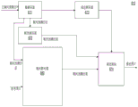
In the embodiment of fig. 7, the video encoder (703) includes an inter encoder (730), an intra encoder (722), a residual calculator (723), a switch (726), a residual encoder (724), a general purpose controller (721), and an entropy encoder (725) coupled together as shown in fig. 7.
The inter encoder (730) is configured to receive samples of a current block (e.g., a processed block), compare the block to one or more reference blocks in a reference picture (e.g., blocks in previous and subsequent pictures), generate inter prediction information (e.g., redundant information descriptions, motion vectors, merge mode information according to inter coding techniques), and calculate an inter prediction result (e.g., a predicted block) using any suitable technique based on the inter prediction information. In some embodiments, the reference picture is a decoded reference picture that is decoded based on encoded video information.
The intra encoder (722) is used to receive samples of a current block (e.g., a processing block), in some cases compare the block to a block already encoded in the same picture, generate quantized coefficients after transformation, and in some cases also generate intra prediction information (e.g., intra prediction direction information according to one or more intra coding techniques). In an embodiment, the intra encoder (722) also calculates an intra prediction result (e.g., a predicted block) based on the intra prediction information and a reference block in the same picture.
The general purpose controller (721) is used to determine general purpose control data and control other components of the video encoder (703) based on the general purpose control data. In an embodiment, a general purpose controller (721) determines a mode of a block and provides a control signal to a switch (726) based on the mode. For example, when the mode is intra mode, the general purpose controller (721) controls the switch (726) to select an intra mode result for use by the residual calculator (723), and controls the entropy encoder (725) to select and add intra prediction information in the code stream; and when the mode is an inter mode, the general purpose controller (721) controls the switch (726) to select an inter prediction result for use by the residual calculator (723), and controls the entropy encoder (725) to select and add inter prediction information in the code stream.
A residual calculator (723) is used to calculate the difference (residual data) between the received block and the prediction result selected from the intra encoder (722) or the inter encoder (730). A residual encoder (724) is operative to operate on the residual data to encode the residual data to generate transform coefficients. In an embodiment, a residual encoder (724) is used to convert residual data from the time domain to the frequency domain and generate transform coefficients. The transform coefficients are then subjected to a quantization process to obtain quantized transform coefficients. In various embodiments, the video encoder (703) also includes a residual decoder (728). A residual decoder (728) is used to perform the inverse transform and generate decoded residual data. The decoded residual data may be suitably used by an intra encoder (722) and an inter encoder (730). For example, inter encoder (730) may generate a decoded block based on decoded residual data and inter prediction information, and intra encoder (722) may generate a decoded block based on decoded residual data and intra prediction information. The decoded blocks are processed appropriately to generate a decoded picture, and in some embodiments, the decoded picture may be buffered in a memory circuit (not shown) and used as a reference picture.
The entropy coder (725) is for formatting the codestream to produce coded blocks. The entropy encoder (725) generates various information according to a suitable standard such as the HEVC standard. In an embodiment, the entropy encoder (725) is used to obtain general control data, selected prediction information (e.g., intra prediction information or inter prediction information), residual information, and other suitable information in the code stream. It should be noted that, according to the disclosed subject matter, there is no residual information when a block is encoded in the merge sub-mode of the inter mode or bi-prediction mode.
Fig. 8 is a diagram of a video decoder (810) according to another embodiment of the present disclosure. A video decoder (810) is for receiving an encoded image that is part of an encoded video sequence and decoding the encoded image to generate a reconstructed picture. In an embodiment, a video decoder (810) is used in place of the video decoder (410) in the fig. 4 embodiment.
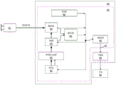
In the fig. 8 embodiment, video decoder (810) includes an entropy decoder (871), an inter-frame decoder (880), a residual decoder (873), a reconstruction module (874), and an intra-frame decoder (872) coupled together as shown in fig. 8.
An entropy decoder (871) is operable to reconstruct from an encoded picture certain symbols representing syntax elements constituting the encoded picture. Such symbols may include, for example, a mode used to encode the block (e.g., intra mode, inter mode, bi-prediction mode, a merge sub-mode of the latter two, or another sub-mode), prediction information (e.g., intra prediction information or inter prediction information) that may identify certain samples or metadata for use by an intra decoder (872) or an inter decoder (880), respectively, residual information in the form of, for example, quantized transform coefficients, and so forth. In an embodiment, when the prediction mode is inter or bi-directional prediction mode, inter prediction information is provided to an inter decoder (880); and providing the intra prediction information to an intra decoder (872) when the prediction type is an intra prediction type. The residual information may be inverse quantized and provided to a residual decoder (873).
An inter decoder (880) is configured to receive inter prediction information and generate an inter prediction result based on the inter prediction information.
An intra-decoder (872) is configured to receive intra-prediction information and generate a prediction result based on the intra-prediction information.
A residual decoder (873) is used to perform inverse quantization to extract dequantized transform coefficients and process the dequantized transform coefficients to convert the residual from the frequency domain to the spatial domain. The residual decoder (873) may also need some control information (to obtain the quantizer parameters QP) and that information may be provided by the entropy decoder (871) (data path not labeled as this is only low-level control information).
The reconstruction module (874) is configured to combine the residuals output by the residual decoder (873) and the prediction results (which may be output by the inter prediction module or the intra prediction module) in the spatial domain to form a reconstructed block, which may be part of a reconstructed picture, which in turn may be part of a reconstructed video. It should be noted that other suitable operations, such as deblocking operations, may be performed to improve visual quality.
It should be noted that video encoder (403), video encoder (603), and video encoder (703), as well as video decoder (410), video decoder (510), and video decoder (810), may be implemented using any suitable techniques. In an embodiment, video encoder (403), video encoder (603), and video encoder (703), and video decoder (410), video decoder (510), and video decoder (810) may be implemented using one or more integrated circuits. In another embodiment, the video encoder (403), the video encoder (603), and the video encoder (703), and the video decoder (410), the video decoder (510), and the video decoder (810) may be implemented using one or more processors executing software instructions.
In some embodiments, such as in HEVC, the primary Transform may include 4-point, 8-point, 16-point, and 32-point Discrete Cosine Transforms (DCTs) type 2(DCT-2), and the Transform kernel matrix may use an 8-bit integer representation (i.e., an 8-bit Transform kernel). The transform kernel matrix of the smaller DCT-2 is part of the transform kernel matrix of the larger DCT-2, as shown in appendix I.
The DCT-2core matrix exhibits symmetric/anti-symmetric properties. Thus, a "partial butterfly" implementation may be supported to reduce the number of operations (e.g., multiply, add, subtract, shift, etc.), and partial butterflies may be used to obtain the same result of matrix multiplication.
In some embodiments, such as in VVC, additional 2-point DCT-2 and 64-point DCT-2 may be included in addition to the 4-point, 8-point, 16-point, and 32-point DCT-2 transforms described above. An example of a 64-point DCT-2 kernel, such as used in VVC, is shown in appendix II in the form of a 64 x 64 matrix.
In addition to DCT-2 and 4x 4DST-7, as used in HEVC, for example, Adaptive Multiple Transform (AMT) (also known as Enhanced Multiple Transform (EMT) or Multiple Transform Selection (MTS)) schemes may be used in VVC, for residual coding of inter and intra coded blocks. In addition to the current transform in HEVC, AMT schemes may use multiple transforms selected from the DCT/DST family. The newly introduced transformation matrix is DST-7, DCT-8. Table 1 shows an example of the basis functions of the DST/DCT for the selection of the N-point input.


TABLE 1
The primary transformation matrix used in VVC, for example, may be used in an 8-bit representation. In an embodiment, the AMT applies the transform matrix to CUs having a width and height less than or equal to 32. Whether AMT is applied may be controlled by a flag (e.g., mts _ flag). When mts _ flag is equal to 0, only DCT-2 is applied to codec the residual data in some examples. When mts _ flag is equal to 1, the index (e.g., mts _ idx) is further signaled using 2 bins to identify, for example, the horizontal and vertical transforms to be used according to table 2, where a type value of 1 indicates that DST-7 is used and a type value of 2 indicates that DCT-8 is used. In Table 2, the specification of trTypeHor and trTypeVer depends on mts _ idx [ x ] [ y ] [ cIdx ].
| mts_idx[xTbY][yTbY][cIdx] | trTypeHor | trTypeVer |
| -1 | 0 | 0 |
| 0 | 1 | 1 |
| 1 | 2 | 1 |
| 2 | 1 | 2 |
| 3 | 2 | 2 |
TABLE 2
In some embodiments, when the signaling-based MTS described above is not used (i.e., explicit MTS), an implicit MTS may be applied. With implicit MTS, the choice of transform is made according to block width and height rather than signaling. For example, with implicit MTS, DST-7 is selected for the shorter side of the block of M N (i.e., the smallest of M and N), and DCT-2 is selected for the longer side of the block (i.e., the largest of M and N).
Exemplary transformation kernels of DST-7 and DCT-8, each of which is a matrix composed of basis vectors, are illustrated in appendix III.
In some examples, such as in VVC, when both the height and width of a codec block are less than or equal to 64, the TB size is the same as the codec block size. When the height or width of the coding and decoding block is greater than 64, the coding and decoding block is further divided into a plurality of sub-blocks, wherein the width and height of each sub-block is less than or equal to 64, when performing a transform (e.g., inverse transform, main inverse transform, etc.) or intra prediction. The transform may be performed once per sub-block.
The relevant syntax and semantics of the MTS in some examples of VVCs may be described in fig. 9 and 10A-10C below (highlighted using label 910 and label 1010). Fig. 9 shows an example of a transform unit syntax. Fig. 10A to 10C show examples of residual codec syntax.
An example of transform unit semantics is as follows. cu _ mts _ flag x0 y0 equal to 1 indicates that the multiple transform selection is applied to the residual samples of the associated luma transform block. cu _ mts _ flag x0 y0 equal to 0 indicates that no multi-transform selection is applied to the residual samples of the associated luma transform block. The array indices x0, y0 indicate the position of the luma sample in the top left corner of the transform block under consideration (top-left) relative to the luma sample in the top left corner of the picture (x0, y 0). When cu _ mts _ flag [ x0] [ y0] is absent, it is inferred to be equal to 0.
An example of residual codec semantics is as follows. mts _ idx [ x0] [ y0] indicates which transform kernels to apply to luma residual samples along the horizontal and vertical directions of the current transform block. The array indices x0, y0 indicate the position of the luma sample in the upper left corner of the transform block under consideration relative to the luma sample in the upper left corner of the picture (x0, y 0). When mts _ idx [ x0] [ y0] is absent, it is inferred to be equal to-1.
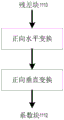
Fig. 11A shows an exemplary forward transform (also referred to as a forward principal transform) performed by an encoder. The forward transform may include a forward horizontal transform and a forward vertical transform. A forward horizontal transform is first applied to a residual block (1110) with residual data to obtain an intermediate block. A forward vertical transform is then applied to the intermediate block to obtain a coefficient block having transform coefficients (1112).
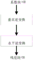
Fig. 11B shows an exemplary inverse transform (also referred to as a main inverse transform or inverse transform) performed by the decoder. In general, the inverse transform matches the forward transform. The main inverse transform may include a main horizontal inverse transform (also referred to as a horizontal inverse transform) and a main vertical inverse transform (also referred to as a vertical inverse transform). In order to match the forward transform, the order of applying the horizontal inverse transform and the vertical inverse transform is switched in the inverse transform. Thus, the vertical inverse transform is first applied to the coefficient block (1122) to obtain an intermediate block. Subsequently, an inverse horizontal transform is applied to the intermediate block to obtain a residual block (1120).
The main transform may refer to a forward main transform or a main inverse transform. The horizontal transformation may refer to a horizontal inverse transformation or a forward horizontal transformation. Similarly, a vertical transform may refer to a vertical inverse transform or a forward vertical transform.
In an example, for example in VVC, at the decoder, a vertical main inverse transform (also referred to as a vertical inverse transform) is performed first, and then after applying the vertical inverse transform, a horizontal main inverse transform (also referred to as a horizontal inverse transform) is performed again, as illustrated in fig. 11B and shown in the text highlighted using the labels 1210 to 1211 in fig. 12A to 12E. Fig. 12A to 12E illustrate examples of a transformation process of scaled transform coefficients.
The main transform, such as a forward main transform or a main inverse transform, may utilize a zero-out (zero-out) method or a zero-output scheme as described below. In some examples, such as in VVC, for a 64-point (or 64-length) DCT-2, only the first 32 coefficients are computed and the remaining coefficients are set to 0. Therefore, for an M × N block that is coded using DCT-2 transform, the min (M,32) x min (N,32) low frequency coefficients of the top left corner (top-left) are calculated. The remaining coefficients are set to 0 and are not signaled. In an example, no residual coefficients are calculated. Entropy coding of the coefficient block may be performed by setting the coefficient block size to min (M,32) x min (N,32) to treat the coefficient coding of the M × N block as a coefficient block of min (M,32) x min (N, 32).
In some examples using MTS, only the first 16 coefficients are computed for 32-point DST-7 or DCT-8, and the remaining coefficients are set to 0. Thus, for an M N block encoded using a DST-7 or DCT-8 transform, the min (M,16) x min (N,16) low frequency coefficients in the upper left corner are preserved. The remaining coefficients may be set to 0 and not signaled. However, unlike the coefficient codec scheme used when applying 64-point zero-out (64-point zero-out) DCT-2, for a 32-point MTS, coefficient codec is performed on the entire M N block even when M or N is greater than 16. However, when a Coefficient Group (CG) is outside the 16 × 16 low frequency region of the upper left corner (i.e., the coefficient group is in the zero output region), a flag (e.g., coded _ sub _ block _ flag) for indicating whether the coefficient group has a non-zero coefficient is not signaled. A zero-output region refers to a region in the coefficient block where the coefficients are zero, and thus, the coefficients in the zero-output region are zero. An example of a residual codec syntax is described below, indicated by the text highlighted by label 1310 in fig. 13.
One major complexity aspect of the main transform (e.g., main inverse or forward main transform) is the average number of Multiplications (MPS) per sample. For example, for an 8 × 8 primary transform, if DST-7 using full matrix multiplication is applied to horizontal and vertical transforms of an 8 × 8 block, the horizontal transform requires 8 multiplications to compute each coefficient and the vertical transform requires 8 multiplications to compute each coefficient, thus using 16 multiplications total per sample.
In some examples, the worst-case MPS is 32 × 32DCT2 and 32 × 64DCT-2, as described below. MPS may also be referred to as multiplication of each coefficient.
For an mxn TU, if non-zero transform coefficients are maintained for the mxn (i.e., M times N) region in the upper left corner of the TU, then the transform coefficients may be passed The number of multiplications (number of multiplications) per coefficient of the inverse transform implemented in the direct matrix multiplication structure is calculated. When N is less than N or M is less than M, a zero output method is applied, and the number of multiplications per coefficient can be reduced.
Also, can be prepared by The number of multiplications for each coefficient of the inverse transform implemented in the half butterfly and half direct matrix multiplication structures is calculated.
In some examples, for example in VVC, up to 32 point DST7/DCT8 transforms (e.g., 4 point DST-7, 8 point DST-7, 16 point DST-7, 32 point DST-7, 4 point DCT-8, 8 point DCT-8, 16 point DCT-8, and 32 point DCT-8) and up to 64 point DCT2 transforms are defined for the primary transforms (e.g., 4 point DCT-2, 8 point DCT-2, 16 point DCT-2, 32 point DCT-2, and 64 point DCT-2). For a 64-point main transform (e.g., 64-point DCT-2), a transform coefficient zero-output scheme (also referred to as a zero-output method, zero-output scheme) may be applied. For the zero-output scheme, for a 64-point main transform, in some examples, only the first 32 coefficients are kept and the remaining coefficients are set to 0. For example, for a 64 × 64 block, the 32 × 32 coefficients in the upper left corner are kept, and the remaining coefficients are set to 0. For a 64 × N block, where N is less than or equal to 32, the left 32 × N coefficients may be retained and the remaining coefficients set to 0. For an mx 64 block, where M is less than or equal to 32, the top mx 32 coefficients may be retained and the remaining coefficients set to 0.
Table 3 shows the number of multiplications per coefficient, where M is the block width, N is the block height, M is the number of coefficients held in the horizontal direction (i.e., in each row), and N is the number of coefficients held in the vertical direction (i.e., in each column). As illustrated in table 3, when the 16 × 16 coefficients in the upper left corner of DST-7/DCT-8 remain unchanged (i.e., m ═ n ═ 16), the worst case (e.g., the number of multiplications for each coefficient is the maximum number of times) includes 32 × 64DCT-2 and 32 × 32 DCT-2. For example, for 32 × 64DCT-2 and 32 × 32DCT-2, the number of multiplications for each coefficient is 40 (using half butterflies) and corresponds to the worst case.
In some examples, a 32 × 32DCT2 without zero output and using a half butterfly, a 32 × 32DST7/DCT8 with zero output (m ═ n ═ 16), a 32 × 16DST7/DCT8 with zero output (m ═ n ═ 16), a 16 × 32DST7/DCT8 with zero output (m ═ n ═ 16) may be employed in video codec.

TABLE 3
In an embodiment, a mode-dependent non-separable secondary transform (NSST) may be used between the forward core transform and quantization at the encoder side and between the de-quantization and inverse core transform at the decoder side. For example, to keep the complexity low, NSST is applied to the low frequency coefficients after the main transform (or kernel transform). When both the width (W) and the height (H) of the transform coefficient block are greater than or equal to 8,8 × 8NSST is applied to the upper left corner 8 × 8 region of the transform coefficient block. Otherwise, when the width W or height H of the transform coefficient block is 4, 4 × 4NSST is applied, and 4 × 4NSST is performed on the upper left-hand corner min (8, W) × min (8, H) region of the transform coefficient block. The above transform selection method is applied to both the luminance component and the chrominance component.
The matrix multiplication implementation of NSST is described below using a 4x4 input block as an example. The 4 × 4 input block X is shown in equation (1) as:

the input block X may be expressed as a vector in equation (2) Wherein:

the inseparable transform can be computed as Wherein the content of the first and second substances,
 a transform coefficient vector is indicated, and T is a 16 × 16 transform matrix. The 16X1 transform coefficient vector is then transformed using the scan order (e.g., horizontal scan order, vertical scan order, or diagonal scan order) of the input block X
 Regrouped into 4x4 blocks. The coefficients with the smaller index may be placed in a 4x4 coefficient block along with the smaller scan index. In some embodiments, the Hypercube-Givens transform (HyGT) with butterfly implementation may be used instead of the matrix multiplication described above to reduce the complexity of NSST.
In an example, a 35 × 3 non-separable quadratic transform may be used for both 4 × 4 and 8 × 8 block sizes, where 35 is the number of transform sets associated with an intra prediction mode and 3 is the number of NSST candidates per intra prediction mode. Table 4 shows an exemplary mapping from intra prediction modes to respective transform sets. According to table 4 showing the mapping from the intra prediction mode to the transform set index, the transform set applied to the luminance/chrominance transform coefficient is indicated by the corresponding luminance/chrominance intra prediction mode. For intra prediction modes greater than 34 corresponding to diagonal prediction directions, the transform coefficient blocks are transposed before/after NSST of the encoder/decoder, respectively.
For each transform set, the selected NSST candidate may be further indicated by an explicitly signaled CU-level NSST index. After transforming the coefficients, CU-level NSST indices are signaled in the code stream of each intra-coded CU, and truncated unary binarization is used for the CU-level NSST indices. For example, the truncation value is 2 for the planar mode or the DC mode, and 3 for the angular intra prediction mode. In an example, the CU-level NSST index is signaled only when there is more than one non-zero coefficient in the CU. The default value is zero and no signaling, which indicates that NSST is not applied to the CU. Each of the values 1 to 3 indicates which NSST candidate is to be applied from the transform set.


TABLE 4
In some embodiments, NSST is not applied to blocks encoded in the transform skip mode. When the CU level NSST index is signaled for the CU and is not equal to zero, NSST is not used for blocks encoded in transform skip mode in the CU. When a CU of a block with all components is coded in transform skip mode or a plurality of non-zero coefficients of a non-transform skip mode CB is less than 2, the CU level NSST index is not signaled for the CU.
Referring to table 3, when DCT-2 is used in the primary transform, the worst-case MPS for the primary transform may correspond to a TB of size 32 × 32 or 32 × 64. In an example, the worst-case MPS uses a multiplication of 1/3 more than the second bad case (e.g., TB size of 64 × 64 or 64 × 32 when DCT2 is used). Aspects of the present disclosure include a method of reducing MPS of a TB of size 32 × 32 or 32 × 64 when a main transform (e.g., a main inverse transform) is performed using DCT-2. Embodiments herein may also be applied to MPS that reduces any suitable TB size and use any suitable transform not limited to DCT-2. Suitable transforms may use transform matrices in the DCT and/or DST families, including DCT-2, DST-7, DST-4, DCT-8, DCT-4, and the like.
The embodiments described herein may be used alone or in any order in combination. Further, embodiments may be implemented by processing circuitry (e.g., at least one processor or at least one integrated circuit). In one example, at least one processor may execute a program stored in a non-transitory computer readable medium.
In the present disclosure, embodiments of DST-7 applicable to MTS candidates may be applicable to DST-4, and vice versa. Similarly, the embodiment of DCT-8, which applies to the MTS candidate, also applies to DCT-4, and vice versa.
In the present disclosure, embodiments applicable to NSST may be applied to Reduced Secondary Transform (RST) as an alternative design to NSST. The second transformation may refer to NSST or RST.
As described above, in fig. 11B, the first order of applying the main inverse transform on the TB is to apply the vertical inverse transform first and then apply the horizontal inverse transform. According to some embodiments, the second order may be used to apply the main inverse transform, wherein the horizontal inverse transform is applied first and the vertical inverse transform is applied after the horizontal inverse transform is applied. Thus, the first order may be switched to the second order. In general, any suitable type of primary transform may be used for the primary inverse transform, such as transform matrices in the DCT and/or DST families including DCT-2, DST-7, DST-4, DCT-8, DCT-4, and so forth. In some embodiments, the main inverse transform is implemented using a DCT-2 transform matrix. In an example, the main inverse transform is implemented with a direct matrix multiplication structure. In another example, the main inverse transform is implemented with a structure of half butterfly and half direct matrix multiplication.
In an embodiment, the second order is used for certain TB sizes (e.g., the first order is switched to the second order). Therefore, the order in which the horizontal inverse transform and the vertical inverse transform are applied may depend on the TB size. TB size may refer to the area of the TB, e.g., the width of M × N, TB, the height of the TB, etc. In the example, when the TB size is 32 × 64, the second order is used (i.e., the horizontal inverse transform is applied before the vertical inverse transform). When the TB size is different from 32 × 64, the first order is used (i.e., the vertical inverse transform is applied before the horizontal inverse transform).
In an embodiment, when the height N of the M × N TB is greater than the width M of the TB, a second order may be used to apply the horizontal inverse transform before the vertical inverse transform. Otherwise, when the height N of the TB is less than or equal to the width M of the TB, the first order may be used such that the vertical inverse transform is applied before the horizontal inverse transform.
A horizontal inverse transform may be performed to transform a first element in the mxn first block to a second element in the mxn second block. The horizontal inverse transform may be referred to as a one-dimensional transform, e.g., an M-length transform, wherein the horizontal inverse transform may be applied to the first block line by line, wherein each line has M first elements. In an embodiment, the second element in the left M columns in the second block is calculated by an inverse horizontal transform without calculating the second element in the right (M-M) columns in the second block, and the second element is zero. When the horizontal inverse transform includes a zero-output method, M is a positive integer smaller than M, the horizontal inverse transform calculates the first M second elements in each line of the second block, and the remaining (M-M) second elements in each line are not calculated and are zero. Thus, the first M second elements (in each row) are held by an M-length transform using a zero-output method. Thus, the number of computations (and the amount of data to be computed and stored) may be reduced by including or using a zero-output approach. When the horizontal inverse transform does not include the zero output method, M may be equal to M.
A vertical inverse transform may be performed to transform the third element in the mxn third block to a fourth element in the mxn fourth block. The vertical inverse transform may be referred to as a one-dimensional transform, e.g., an N-length transform, wherein the vertical inverse transform may be applied column-wise to a third block, wherein each column has N third elements. In an embodiment, the fourth element in the top N rows in the fourth block is calculated by a vertical inverse transform, while the fourth element in the bottom (N-N) rows in the fourth block is not calculated and is zero. When the vertical inverse transform includes a zero output method, N is a positive integer smaller than N, the vertical inverse transform calculates the first N fourth elements in each column of the fourth block, and the remaining (N-N) fourth elements in each column are not calculated and are zero. Therefore, the first N fourth elements (in each column) are held by N-length transformation using the zero-output method. Thus, the number of computations (and the amount of data to be computed and stored) can be reduced by including a zero-output method. When the vertical inverse transform does not include the zero output method, N may be equal to N.
A main inverse transform (e.g., DCT-2) may be applied to a coefficient block having a TB size of M × N to obtain an M × N residual block. According to an embodiment of the present disclosure, first residual data in an mxn region in the residual block will be determined by the main inverse transform and second residual data outside the mxn region in the residual block will not be calculated by the main inverse transform, wherein M is less than or equal to M and N is less than or equal to N. As described above, when the horizontal inverse transform includes the zero output method, M is smaller than M. When the vertical inverse transform includes a zero-output method, N is smaller than N. When the ratio M/M is greater than or equal to the ratio N/N, the horizontal inverse transform is applied before the vertical inverse transform is applied. Otherwise, when the ratio M/M is smaller than the ratio N/N, the vertical inverse transform is applied before the horizontal inverse transform is applied.
Typically, a main inverse transform is performed to transform the transform coefficients in the coefficient block into residual data in a residual block. TB may refer to coefficient blocks and/or residual blocks. The TB size, the size of the coefficient block, and the size of the residual block are mxn. When the ratio M/M is greater than or equal to the ratio N/N, the horizontal inverse transform is applied before the vertical inverse transform is applied. Thus, the first block is an M × N coefficient block, and the first data is a transform coefficient. The second block is an M × N intermediate block, and the second data is intermediate data. The third block is identical to the second block, and the third data is identical to the second data. The fourth block is an M × N residual block, and the fourth data is residual data.
According to some embodiments, the amount of data calculated or maintained in a one-dimensional transform applied to a TB using a zero-output method may be determined based on the TB size. As described above, the one-dimensional transform may refer to a horizontal inverse transform or a vertical inverse transform. In some embodiments, the main inverse transform is performed using the first order shown in fig. 11B to apply the vertical inverse transform first, followed by the horizontal inverse transform. When the TB size is 32 × 64 and the width is 32 and the height is 64, a 64-length vertical inverse transform is applied by zero output to transform a 32 × 64 coefficient block with transform coefficients into an intermediate block with intermediate data by computing the top 16 rows of intermediate blocks (i.e., the first 16 segments of intermediate data in each column). The remaining intermediate data in the intermediate block is not calculated and is zero (e.g., the remaining intermediate data may be set to zero). In some examples, when the TB size is different from 32 × 64 (e.g., 16 × 64), a 64-length inverse vertical transform computes the top 32 rows of intermediate data in the intermediate block, and the remaining intermediate data in the intermediate block is not computed and is zero.
When the TB size is 32 × 64 and the first order is used, a 32-length horizontal inverse transform may be applied by calculating the left 16 columns of residual blocks (i.e., the first 16 pieces of residual data in each row) by zero output to transform the 32 × 64 intermediate block with intermediate data into a residual block with residual data. The remaining residual data in the residual block is not calculated and is zero (e.g., the remaining residual data may be set to zero).
In some examples, when the TB size is M × 32, where M is less than 32, the 32-length inverse vertical transform does not apply a zero output scheme. In some examples, when the TB size is 32 × N, where N is less than 32, the 32-length horizontal inverse transform does not apply a zero output scheme.
According to some embodiments, the amount of data to be calculated using a one-dimensional transform may be determined based on whether the one-dimensional transform is an inverse horizontal transform or an inverse vertical transform. For example, the zero-output scheme may be used for only one of the one-dimensional transforms. In an embodiment, the main inverse transform is performed using a first order to apply the vertical inverse transform first, followed by the horizontal inverse transform. The TB size is 32 × 32. In an example, the 32-length vertical transform does not apply the zero-output method. Thus, a 32-length vertical inverse transform calculates or holds all the intermediate data in the 32 rows of the intermediate block. The 32-length horizontal inverse transform uses a zero-output method to compute or hold the left 16 columns of the residual block. The remaining residual data in the residual block is not calculated and is zero (e.g., the remaining residual data may be set to zero). In an example, a 32-length inverse vertical transform uses a zero-output method to compute or hold the top 16 rows of the middle block. The remaining intermediate data in the intermediate block is not calculated and is zero (e.g., the remaining intermediate data may be set to zero). Meanwhile, the 32-length horizontal inverse transform does not apply the zero output method. Thus, a 32-length horizontal inverse transform computes or holds all the residual data in the 32 columns of the residual block.
When the first main inverse transform is applied to the TB without an inverse secondary inverse transform, the first MPS is attributed to the first main inverse transform. When a second primary inverse transform (second inverse primary transform) and a secondary inverse transform are applied to the TB, a second MPS (also referred to as a combined MPS) may include multiplication in both the second primary inverse transform and the secondary inverse transform. When the first inverse main transform is the same as the second inverse main transform, the second MPS may be larger than the first MPS because additional multiplications are used in the second inverse transform. The following embodiments may be implemented to constrain or reduce the combined MPS to within MPS limits (e.g., the worst-case MPS shown in table 3) to improve codec efficiency.
According to aspects of the present disclosure, the number of non-zero transform coefficients that are preserved using a zero-output scheme and/or whether a zero-output method is used in the main inverse transform may depend on whether a secondary transform is applied. Therefore, the MPS of the combination of the main inverse transform and the quadratic transform can be reduced. Returning to the first main inverse transform and the second main inverse transform, according to aspects of the present disclosure, the first main inverse transform may calculate or maintain a first number of residual data, and the second main inverse transform may calculate or maintain a second number of residual data, wherein the second number of residual data is less than the first number of residual data, such that the combined MPS (i.e., the second MPS) is similar to the first MPS. In an example, at least one-dimensional transform (e.g., a horizontal inverse transform or a vertical inverse transform) of the second main inverse transform includes a zero-output method. The one-dimensional transform of the first main inverse transform may also include a zero-output method, however, the second main inverse transform may calculate or maintain less residual data than the first main inverse transform.
As described above, the main inverse transform and the quadratic inverse transform may be applied to the TB and produce a combined MPS. In general, the primary inverse transform may comprise different types (e.g., DCT-2, DST-7, DST-4, DCT-8, DCT-4, etc.). According to aspects of the present disclosure, whether to use a zero output method and/or the amount of data to be calculated or held in a coefficient block when the zero output method is used in the secondary inverse transform may be determined based on the type of the main inverse transform, so that the combined MPS may be reduced. For example, when the main inverse transform is more complicated (e.g., MPS of the main inverse transform is relatively large), the amount of data to be calculated or held in the coefficient block when the zero-output method is used in the secondary inverse transform can be further reduced.
According to aspects of the present disclosure, the zero output method may be performed according to an intra prediction mode for the TB. In some embodiments, whether to use the zero output method and the amount of data to be calculated or maintained when using the zero output method may be determined based on the intra prediction mode.
In an embodiment, whether the horizontal inverse transform or the vertical inverse transform is performed using the zero-output method may depend on an intra prediction direction for the TB. The intra prediction direction corresponds to an intra prediction mode. In an example, when the intra prediction direction is close to the horizontal prediction direction, a zero output method is applied to the horizontal inverse transform. In an example, when the intra prediction direction is close to the vertical prediction direction, a zero output method is applied to the vertical inverse transform. For example, the horizontal prediction direction is indexed by the value Hor, and the vertical prediction direction is indexed by the value Ver. A threshold thres may be defined to determine how close the intra prediction mode is to the horizontal mode corresponding to the horizontal prediction direction or the vertical mode corresponding to the vertical prediction direction. It is determined that the intra prediction mode (or intra prediction direction) indexed within the range of [ Hor-thres, Hor + thres ] is close to the horizontal prediction direction. It is determined that the intra prediction mode indexed in the range of [ Ver-thres, Ver + thres ] is close to the vertical prediction direction. Example values of threshold thres include, but are not limited to, 1,2, 3,4, …, and 16.
In an embodiment, the amount of data to be calculated or maintained when the zero output method is used in the main inverse transform and/or the secondary transform may be determined based on the intra prediction direction of the TB.
Fig. 14 shows a flowchart outlining a method (1400) according to an embodiment of the present disclosure. The method (1400) may be used in reconstruction of a block encoded in intra mode to generate a prediction block for the reconstructed block. In some examples, the method (1400) may be used for reconstruction of a block encoded in inter mode. In various embodiments, the method (1400) is performed by processing circuitry, e.g., processing circuitry in terminal devices (310), (320), (330), and (340), processing circuitry that performs the functions of the video encoder (403), processing circuitry that performs the functions of the video decoder (410), processing circuitry that performs the functions of the video decoder (510), processing circuitry that performs the functions of the video encoder (603), and so on. In some embodiments, the method (1400) is implemented in software instructions, such that when executed by processing circuitry, the processing circuitry performs the method (1400). The method starts (S1401) and proceeds to (S1410).
At (S1410), encoding information for a TB (e.g., a coefficient block) from an encoded video bitstream is decoded. The coding information may indicate a TB size (or referred to as the size of a coefficient block). As described above, TB size may refer to the area, width, height, etc. of the TB.
At (S1420), an order in which the horizontal inverse transform and the vertical inverse transform of the main inverse transform are to be performed may be determined based on the size of the coefficient block. The transform coefficients of the coefficient block may be transformed into residual data of a residual block by a main inverse transform. As described above, in an example, the order is a first order. In an example, the order is a second order.
At (S1430), it may be determined whether the TB size satisfies a condition, as described above. The condition may be whether the TB size is 32 × 64. The condition may be that the height N of the M × N coefficient block is greater than the width M of the coefficient block. The condition may compare a first ratio to a second ratio, where the first ratio (e.g., M/M) is the amount of data calculated for a row relative to the total amount of data in the row, and the second ratio (N/N) is the amount of data calculated for a column relative to the total amount of data in the column. When it is determined that the TB size satisfies the condition, the method (1400) proceeds to (S1440). Otherwise, the method (1400) proceeds to (S1450).
At (S1440), a vertical inverse transform is performed after performing a horizontal inverse transform on the transform coefficients of the coefficient block, and thus a second order is used.
At (S1450), a horizontal inverse transform is performed after a vertical inverse transform is performed on the transform coefficients of the coefficient block, and thus the first order is used.
At (S1460), samples in a residual block may be reconstructed based on the residual data.
The method (1400) may be modified as appropriate. For example, at least one step may be modified, omitted, or combined. For example, the (S1420) and (S1430) may be combined. One or more additional steps may be added. The order in which the method (1400) is performed may also be modified.
Fig. 15 shows a flowchart outlining a method (1500) according to an embodiment of the present disclosure. The method (1500) may be used in the reconstruction of a block coded in intra mode to generate a prediction block for the block in reconstruction. In some examples, the method (1500) may be used for reconstruction of a block encoded in inter mode. In various embodiments, method (1500) is performed by processing circuitry, e.g., processing circuitry in terminal devices (310), (320), (330), and (340), processing circuitry that performs the functions of video encoder (403), processing circuitry that performs the functions of video decoder (410), processing circuitry that performs the functions of video decoder (510), processing circuitry that performs the functions of video encoder (603), and so forth. In some embodiments, the method (1500) is implemented in software instructions, such that when the processing circuitry executes the software instructions, the processing circuitry performs the method (1500). The method starts (S1501) and proceeds to (S1510).
At (S1510), encoding information for a TB (e.g., a coefficient block) from an encoded video bitstream is decoded. The coding information may indicate a TB size (or referred to as the size of a coefficient block).
At (S1520), it may be determined whether to reduce the number of calculations (or the amount of data to be calculated) of one of the horizontal inverse transform and the vertical inverse transform in the main inverse transform based on the size of the coefficient block. The transform coefficients of the coefficient block may be transformed into residual data of a residual block by a main inverse transform. In an embodiment, a first order is used. A vertical inverse transform may transform the transform coefficients of the coefficient block into intermediate data of the intermediate block, and a horizontal inverse transform may transform the intermediate data into residual data in the residual block. In an example, reducing the number of computations in a one-dimensional transform (e.g., a horizontal inverse transform or a vertical inverse transform) means that the one-dimensional transform includes a zero-output method in which the first 16 rows (for the horizontal inverse transform) or columns (for the vertical inverse transform) of data are computed and the remaining data are not computed. For example, when the TB size is one of 32 × 64 and 32 × 32, it is determined that the number of computations in the one-dimensional transform is reduced. When it is determined that the number of computations in the one-dimensional transform is to be reduced, the method (1500) proceeds to (S1530).
At (S1530), it may be determined whether the number of calculations in the horizontal inverse transform is to be reduced. When the number of calculations in the horizontal inverse transform is to be reduced, the method (1500) proceeds to (S1540). Otherwise, the method (1500) proceeds to (S1550).
May be appropriately modified (S1530). For example, instead of determining whether to reduce the number of calculations in the horizontal inverse transform at (S1530), it may be determined whether to reduce the number of calculations in the vertical inverse transform.
At (S1540), a main inverse transform is performed, in which the horizontal inverse transform includes a zero output method, and the left 16 columns of residual data in the residual block are calculated by the horizontal inverse transform, and the remaining residual data in the residual block is not calculated and is zero, as described above.
In an example, at (S1540), the vertical inverse transform further includes a zero-output method.
At (S1550), a main inverse transform is performed, wherein the vertical inverse transform includes a zero output method, and thus the top 16 rows of intermediate data in the intermediate block are calculated by the vertical inverse transform, and the remaining intermediate data in the intermediate block are not calculated and are zero, as described above.
At (S1560), a residual block may be reconstructed based on the residual data.
The method (1500) may be modified as appropriate. For example, at least one step may be modified, omitted, or combined. For example, steps (S1520) and (S1530) may be combined into a single step. One or more additional steps may be added. The order in which the method (1500) is performed may also be modified.
In an example, one or more steps of the method (1400) and one or more steps of the method (1500) can be modified and combined.
The techniques described above may be implemented as computer software via computer readable instructions and physically stored in one or more computer readable media. For example, fig. 16 illustrates a computer system (1600) suitable for implementing certain embodiments of the disclosed subject matter.
The computer software may be encoded in any suitable machine code or computer language, and by assembly, compilation, linking, etc., mechanisms create code that includes instructions that are directly executable by one or more computer Central Processing Units (CPUs), Graphics Processing Units (GPUs), etc., or by way of transcoding, microcode, etc.
The instructions may be executed on various types of computers or components thereof, including, for example, personal computers, tablets, servers, smartphones, gaming devices, internet of things devices, and so forth.
The components illustrated in FIG. 16 for computer system (1600) are exemplary in nature and are not intended to limit the scope of use or functionality of the computer software implementing embodiments of the present application in any way. Neither should the configuration of components be interpreted as having any dependency or requirement relating to any one or combination of components illustrated in the exemplary embodiment of computer system (1600).
The computer system (1600) may include some human interface input devices. Such human interface input devices may respond to input from one or more human users through tactile input (e.g., keyboard input, swipe, data glove movement), audio input (e.g., sound, applause), visual input (e.g., gestures), olfactory input (not shown). The human-machine interface device may also be used to capture media that does not necessarily directly relate to human conscious input, such as audio (e.g., voice, music, ambient sounds), images (e.g., scanned images, photographic images obtained from still-image cameras), video (e.g., two-dimensional video, three-dimensional video including stereoscopic video).
The human interface input device may include one or more of the following (only one of which is depicted): keyboard (1601), mouse (1602), touch pad (1603), touch screen (1610), data glove (not shown), joystick (1605), microphone (1606), scanner (1607), camera (1608).
The computer system (1600) may also include certain human interface output devices. Such human interface output devices may stimulate the senses of one or more human users through, for example, tactile outputs, sounds, light, and olfactory/gustatory sensations. Such human interface output devices may include tactile output devices (e.g., tactile feedback through a touch screen (1610), data glove (not shown), or joystick (1605), but there may also be tactile feedback devices that do not act as input devices), audio output devices (e.g., speakers (1609), headphones (not shown)), visual output devices (e.g., screens (1610) including cathode ray tube screens, liquid crystal screens, plasma screens, organic light emitting diode screens, each with or without touch screen input functionality, each with or without haptic feedback functionality-some of which may output two-dimensional visual output or more than three-dimensional output by means such as stereoscopic picture output; virtual reality glasses (not shown), holographic displays, and smoke boxes (not shown)), and printers (not shown).
The computer system (1600) may also include human-accessible storage devices and their associated media such as optical media including compact disc read-only/rewritable (CD/DVD ROM/RW) (1620) or similar media (1621) with CD/DVD, thumb drive (1622), removable hard drive or solid state drive (1623), conventional magnetic media such as magnetic tape and floppy disk (not shown), ROM/ASIC/PLD based proprietary devices such as security dongle (not shown), and the like.
Those skilled in the art will also appreciate that the term "computer-readable medium" used in connection with the disclosed subject matter does not include transmission media, carrier waves, or other transitory signals.
The computer system (1600) may also include an interface to one or more communication networks. For example, the network may be wireless, wired, optical. The network may also be a local area network, a wide area network, a metropolitan area network, a vehicular network, an industrial network, a real-time network, a delay tolerant network, and so forth. The network also includes ethernet, wireless local area networks, local area networks such as cellular networks (GSM, 3G, 4G, 5G, LTE, etc.), television wired or wireless wide area digital networks (including cable, satellite, and terrestrial broadcast television), automotive and industrial networks (including CANBus), and so forth. Some networks typically require external network interface adapters for connecting to some general purpose data ports or peripheral buses (1649) (e.g., USB ports of computer system (1600)); other systems are typically integrated into the core of computer system (1600) by connecting to a system bus as described below (e.g., an ethernet interface to a PC computer system or a cellular network interface to a smartphone computer system). Using any of these networks, the computer system (1600) may communicate with other entities. The communication may be unidirectional, for reception only (e.g., wireless television), unidirectional for transmission only (e.g., CAN bus to certain CAN bus devices), or bidirectional, for example, to other computer systems over a local or wide area digital network. Each of the networks and network interfaces described above may use certain protocols and protocol stacks.
The human interface device, human accessible storage device, and network interface described above may be connected to the core (1640) of the computer system (1600).
The core (1640) may include one or more Central Processing Units (CPUs) (1641), Graphics Processing Units (GPUs) (1642), special purpose programmable processing units in the form of Field Programmable Gate Arrays (FPGAs) (1643), hardware accelerators (1644) for specific tasks, and so on. These devices, as well as Read Only Memory (ROM) (1645), random access memory (1646), internal mass storage (e.g., internal non-user accessible hard drives, solid state drives, etc.) (1647), etc. may be connected via a system bus (1648). In some computer systems, the system bus (1648) may be accessed in the form of one or more physical plugs, so as to be expandable by additional central processing units, graphics processing units, and the like. The peripheral devices may be attached directly to the system bus (1648) of the core or connected through a peripheral bus (1649). The architecture of the peripheral bus includes peripheral controller interface PCI, universal serial bus USB, etc.
The CPU (1641), GPU (1642), FPGA (1643), and accelerator (1644) may execute certain instructions, which in combination may constitute the computer code described above. The computer code can be stored in ROM (1645) or RAM (1646). Transitional data may also be stored in RAM (1646), while persistent data may be stored in, for example, internal mass storage (1647). Fast storage and retrieval for any memory device can be achieved through the use of caches, which may be closely associated with one or more of CPU (1641), GPU (1642), mass storage (1647), ROM (1645), RAM (1646), and so forth.
The computer-readable medium may have computer code thereon for performing various computer-implemented operations. The media and computer code may be those specially designed and constructed for the purposes of the present application, or they may be of the kind well known and available to those having skill in the computer software arts.
By way of example, and not limitation, a computer system having architecture (1600), and in particular cores (1640), may provide functionality as a processor (including CPUs, GPUs, FPGAs, accelerators, and the like) that executes software contained in one or more tangible computer-readable media. Such computer-readable media can be media associated with the user-accessible mass storage described above, as well as particular storage having a non-volatile core (1640), such as core internal mass storage (1647) or ROM (1645). Software implementing various embodiments of the present application may be stored in such a device and executed by the core (1640). The computer-readable medium may include one or more memory devices or chips, according to particular needs. The software may cause the core (1640), and in particular the processors therein (including CPUs, GPUs, FPGAs, etc.), to perform certain processes or certain parts of certain processes described herein, including defining data structures stored in RAM (1646) and modifying such data structures according to software-defined processes. Additionally or alternatively, the computer system may provide functionality that is logically hardwired or otherwise embodied in circuitry (e.g., accelerator (1644)) that may operate in place of or in conjunction with software to perform certain processes or certain portions of certain processes described herein. Where appropriate, reference to software may include logic and vice versa. Where appropriate, reference to a computer-readable medium may include circuitry (e.g., an Integrated Circuit (IC)) storing executable software, circuitry comprising executable logic, or both. The present application includes any suitable combination of hardware and software.
Appendix A: acronyms
JEM Joint exploration model
VVC next generation video coding
BMS reference set
MV motion vector
HEVC (high efficiency video coding)
SEI supplemental enhancement information
VUI video usability information
GOPs group of pictures
TUs transformation unit
PUs prediction unit
Coding tree units for CTUs
Coding tree blocks of CTBs
PBs prediction block
HRD hypothetical reference decoder
SNR to SNR ratio
CPU Central Processing Unit (CPU)
GPUs graphics processing units
CRT cathode ray tube
LCD (liquid crystal display)
OLED organic light emitting diode
CD-disc
DVD-digitalized video optical disk
ROM-ROM
RAM random access memory
ASIC application specific integrated circuit
PLD programmable logic device
LAN (local area network)
GSM global system for mobile communications
LTE Long term evolution
CANBus controller area network bus
USB (Universal Serial bus)
PCI peripheral interconnect
FPGA field programmable gate array
SSD solid state drive
IC integrated circuit
CU coding unit
While the application has described several exemplary embodiments, various modifications, arrangements, and equivalents of the embodiments are within the scope of the application. It will thus be appreciated that those skilled in the art will be able to devise various systems and methods which, although not explicitly shown or described herein, embody the principles of the application and are thus within its spirit and scope.
Appendix I
4x4 transformation
{64,64,64,64}
{83,36,-36,-83}
{64,-64,-64,64}
{36,-83,83,-36}
8x8 transformation
{64,64,64,64,64,64,64,64}
{89,75,50,18,-18,-50,-75,-89}
{83,36,-36,-83,-83,-36,36,83}
{75,-18,-89,-50,50,89,18,-75}
{64,-64,-64,64,64,-64,-64,64}
{50,-89,18,75,-75,-18,89,-50}
{36,-83,83,-36,-36,83,-83,36}
{18,-50,75,-89,89,-75,50,-18}
16x16 transformation
{64 64 64 64 64 64 64 64 64 64 64 64 64 64 64 64}
{90 87 80 70 57 43 25 9 -9-25-43-57-70-80-87-90}
{89 75 50 18-18-50-75-89-89-75-50-18 18 50 75 89}
{87 57 9-43-80-90-70-25 25 70 90 80 43 -9-57-87}
{83 36-36-83-83-36 36 83 83 36-36-83-83-36 36 83}
{80 9-70-87-25 57 90 43-43-90-57 25 87 70 -9-80}
{75-18-89-50 50 89 18-75-75 18 89 50-50-89-18 75}
{70-43-87 9 90 25-80-57 57 80-25-90 -9 87 43-70}
{64-64-64 64 64-64-64 64 64-64-64 64 64-64-64 64}
{57-80-25 90 -9-87 43 70-70-43 87 9-90 25 80-57}
{50-89 18 75-75-18 89-50-50 89-18-75 75 18-89 50}
{43-90 57 25-87 70 9-80 80 -9-70 87-25-57 90-43}
{36-83 83-36-36 83-83 36 36-83 83-36-36 83-83 36}
{25-70 90-80 43 9-57 87-87 57 -9-43 80-90 70-25}
{18-50 75-89 89-75 50-18-18 50-75 89-89 75-50 18}
{9-25 43-57 70-80 87-90 90-87 80-70 57-43 25 -9}
32x32 transformation
{64 64 64 64 64 64 64 64 64 64 64 64 64 64 64 64 64 64 64 64 64 64 64 64 64 64 64 64 64 64 64 64}
{90 90 88 85 82 78 73 67 61 54 46 38 31 22 13 4 -4-13-22-31-38-46-54-61-67-73-78-82-85-88-90-90}
{90 87 80 70 57 43 25 9 -9-25-43-57-70-80-87-90-90-87-80-70-57-43-25 -9 9 25 43 57 70 80 87 90}
{90 82 67 46 22 -4-31-54-73-85-90-88-78-61-38-13 13 38 61 78 88 90 85 73 54 31 4-22-46-67-82-90}
{89 75 50 18-18-50-75-89-89-75-50-18 18 50 75 89 89 75 50 18-18-50-75-89-89-75-50-18 18 50 75 89}
{88 67 31-13-54-82-90-78-46 -4 38 73 90 85 61 22-22-61-85-90-73-38 4 46 78 90 82 54 13-31-67-88}
{87 57 9-43-80-90-70-25 25 70 90 80 43 -9-57-87-87-57 -9 43 80 90 70 25-25-70-90-80-43 9 57 87}
{85 46-13-67-90-73-22 38 82 88 54 -4-61-90-78-31 31 78 90 61 4-54-88-82-38 22 73 90 67 13-46-85}
{83 36-36-83-83-36 36 83 83 36-36-83-83-36 36 83 83 36-36-83-83-36 36 83 83 36-36-83-83-36 36 83}
{82 22-54-90-61 13 78 85 31-46-90-67 4 73 88 38-38-88-73 -4 67 90 46-31-85-78-13 61 90 54-22-82}
{80 9-70-87-25 57 90 43-43-90-57 25 87 70 -9-80-80 -9 70 87 25-57-90-43 43 90 57-25-87-70 9 80}
{78 -4-82-73 13 85 67-22-88-61 31 90 54-38-90-46 46 90 38-54-90-31 61 88 22-67-85-13 73 82 4-78}
{75-18-89-50 50 89 18-75-75 18 89 50-50-89-18 75 75-18-89-50 50 89 18-75-75 18 89 50-50-89-18 75}
{73-31-90-22 78 67-38-90-13 82 61-46-88 -4 85 54-54-85 4 88 46-61-82 13 90 38-67-78 22 90 31-73}
{70-43-87 9 90 25-80-57 57 80-25-90-9 87 43-70-70 43 87 -9-90-25 80 57-57-80 25 90 9-87-43 70}
{67-54-78 38 85-22-90 4 90 13-88-31 82 46-73-61 61 73-46-82 31 88-13-90 -4 90 22-85-38 78 54-67}
{64-64-64 64 64-64-64 64 64-64-64 64 64-64-64 64 64-64-64 64 64-64-64 64 64-64-64 64 64-64-64 64}
{61-73-46 82 31-88-13 90 -4-90 22 85-38-78 54 67-67-54 78 38-85-22 90 4-90 13 88-31-82 46 73-61}
{57-80-25 90 -9-87 43 70-70-43 87 9-90 25 80-57-57 80 25-90 9 87-43-70 70 43-87 -9 90-25-80 57}
{54-85 -4 88-46-61 82 13-90 38 67-78-22 90-31-73 73 31-90 22 78-67-38 90-13-82 61 46-88 4 85-54}
{50-89 18 75-75-18 89-50-50 89-18-75 75 18-89 50 50-89 18 75-75-18 89-50-50 89-18-75 75 18-89 50}
{46-90 38 54-90 31 61-88 22 67-85 13 73-82 4 78-78 -4 82-73-13 85-67-22 88-61-31 90-54-38 90-46}
{43-90 57 25-87 70 9-80 80 -9-70 87-25-57 90-43-43 90-57-25 87-70 -9 80-80 9 70-87 25 57-90 43}
{38-88 73 -4-67 90-46-31 85-78 13 61-90 54 22-82 82-22-54 90-61-13 78-85 31 46-90 67 4-73 88-38}
{36-83 83-36-36 83-83 36 36-83 83-36-36 83-83 36 36-83 83-36-36 83-83 36 36-83 83-36-36 83-83 36}
{31-78 90-61 4 54-88 82-38-22 73-90 67-13-46 85-85 46 13-67 90-73 22 38-82 88-54 -4 61-90 78-31}
{25-70 90-80 43 9-57 87-87 57 -9-43 80-90 70-25-25 70-90 80-43-9 57-87 87-57 9 43-80 90-70 25}
{22-61 85-90 73-38 -4 46-78 90-82 54-13-31 67-88 88-67 31 13-54 82-90 78-46 4 38-73 90-85 61-22}
{18-50 75-89 89-75 50-18-18 50-75 89-89 75-50 18 18-50 75-89 89-75 50-18-18 50-75 89-89 75-50 18}
{13-38 61-78 88-90 85-73 54-31 4 22-46 67-82 90-90 82-67 46-22 -4 31-54 73-85 90-88 78-61 38-13}
{9-25 43-57 70-80 87-90 90-87 80-70 57-43 25 -9 -9 25-43 57-70 80-87 90-90 87-80 70-57 43-25 9}
{4-13 22-31 38-46 54-61 67-73 78-82 85-88 90-90 90-90 88-85 82-78 73-67 61-54 46-38 31-22 13 -4}
Appendix II
64-Point DCT-2core (64-point DCT-2core)
{
{aa,aa,aa,aa,aa,aa,aa,aa,aa,aa,aa,aa,aa,aa,aa,aa,aa,aa,aa,aa,aa,aa,aa,aa,aa,aa,aa,aa,aa,aa,aa,aa,aa,aa,aa,aa,aa,aa,aa,aa,aa,aa,aa,aa,aa,aa,aa,aa,aa,aa,aa,aa,aa,aa,aa,aa,aa,aa,aa,aa,aa,aa,aa,aa}
{bf,bg,bh,bi,bj,bk,bl,bm,bn,bo,bp,bq,br,bs,bt,bu,bv,bw,bx,by,bz,ca,cb,cc,cd,ce,cf,cg,ch,ci,cj,ck,-ck,-cj,-ci,-ch,-cg,-cf,-ce,-cd,-cc,-cb,-ca,-bz,-by,-bx,-bw,-bv,-bu,-bt,-bs,-br,-bq,-bp,-bo,-bn,-bm,-bl,-bk,-bj,-bi,-bh,-bg,-bf}
{ap,aq,ar,as,at,au,av,aw,ax,ay,az,ba,bb,bc,bd,be,-be,-bd,-bc,-bb,-ba,-az,-ay,-ax,-aw,-av,-au,-at,-as,-ar,-aq,-ap,-ap,-aq,-ar,-as,-at,-au,-av,-aw,-ax,-ay,-az,-ba,-bb,-bc,-bd,-be,be,bd,bc,bb,ba,az,ay,ax,aw,av,au,at,as,ar,aq,ap}
{bg,bj,bm,bp,bs,bv,by,cb,ce,ch,ck,-ci,-cf,-cc,-bz,-bw,-bt,-bq,-bn,-bk,-bh,-bf,-bi,-bl,-bo,-br,-bu,-bx,-ca,-cd,-cg,-cj,cj,cg,cd,ca,bx,bu,br,bo,bl,bi,bf,bh,bk,bn,bq,bt,bw,bz,cc,cf,ci,-ck,-ch,-ce,-cb,-by,-bv,-bs,-bp,-bm,-bj,-bg}
{ah,ai,aj,ak,al,am,an,ao,-ao,-an,-am,-al,-ak,-aj,-ai,-ah,-ah,-ai,-aj,-ak,-al,-am,-an,-ao,ao,an,am,al,ak,aj,ai,ah,ah,ai,aj,ak,al,am,an,ao,-ao,-an,-am,-al,-ak,-aj,-ai,-ah,-ah,-ai,-aj,-ak,-al,-am,-an,-ao,ao,an,am,al,ak,aj,ai,ah}
{bh,bm,br,bw,cb,cg,-ck,-cf,-ca,-bv,-bq,-bl,-bg,-bi,-bn,-bs,-bx,-cc,-ch,cj,ce,bz,bu,bp,bk,bf,bj,bo,bt,by,cd,ci,-ci,-cd,-by,-bt,-bo,-bj,-bf,-bk,-bp,-bu,-bz,-ce,-cj,ch,cc,bx,bs,bn,bi,bg,bl,bq,bv,ca,cf,ck,-cg,-cb,-bw,-br,-bm,-bh}
{aq,at,aw,az,bc,-be,-bb,-ay,-av,-as,-ap,-ar,-au,-ax,-ba,-bd,bd,ba,ax,au,ar,ap,as,av,ay,bb,be,-bc,-az,-aw,-at,-aq,-aq,-at,-aw,-az,-bc,be,bb,ay,av,as,ap,ar,au,ax,ba,bd,-bd,-ba,-ax,-au,-ar,-ap,-as,-av,-ay,-bb,-be,bc,az,aw,at,aq}
{bi,bp,bw,cd,ck,-ce,-bx,-bq,-bj,-bh,-bo,-bv,-cc,-cj,cf,by,br,bk,bg,bn,bu,cb,ci,-cg,-bz,-bs,-bl,-bf,-bm,-bt,-ca,-ch,ch,ca,bt,bm,bf,bl,bs,bz,cg,-ci,-cb,-bu,-bn,-bg,-bk,-br,-by,-cf,cj,cc,bv,bo,bh,bj,bq,bx,ce,-ck,-cd,-bw,-bp,-bi}
{ad,ae,af,ag,-ag,-af,-ae,-ad,-ad,-ae,-af,-ag,ag,af,ae,ad,ad,ae,af,ag,-ag,-af,-ae,-ad,-ad,-ae,-af,-ag,ag,af,ae,ad,ad,ae,af,ag,-ag,-af,-ae,-ad,-ad,-ae,-af,-ag,ag,af,ae,ad,ad,ae,af,ag,-ag,-af,-ae,-ad,-ad,-ae,-af,-ag,ag,af,ae,ad}
{bj,bs,cb,ck,-cc,-bt,-bk,-bi,-br,-ca,-cj,cd,bu,bl,bh,bq,bz,ci,-ce,-bv,-bm,-bg,-bp,-by,-ch,cf,bw,bn,bf,bo,bx,cg,-cg,-bx,-bo,-bf,-bn,-bw,-cf,ch,by,bp,bg,bm,bv,ce,-ci,-bz,-bq,-bh,-bl,-bu,-cd,cj,ca,br,bi,bk,bt,cc,-ck,-cb,-bs,-bj}
{ar,aw,bb,-bd,-ay,-at,-ap,-au,-az,-be,ba,av,aq,as,ax,bc,-bc,-ax,-as,-aq,-av,-ba,be,az,au,ap,at,ay,bd,-bb,-aw,-ar,-ar,-aw,-bb,bd,ay,at,ap,au,az,be,-ba,-av,-aq,-as,-ax,-bc,bc,ax,as,aq,av,ba,-be,-az,-au,-ap,-at,-ay,-bd,bb,aw,ar}
{bk,bv,cg,-ce,-bt,-bi,-bm,-bx,-ci,cc,br,bg,bo,bz,ck,-ca,-bp,-bf,-bq,-cb,cj,by,bn,bh,bs,cd,-ch,-bw,-bl,-bj,-bu,-cf,cf,bu,bj,bl,bw,ch,-cd,-bs,-bh,-bn,-by,-cj,cb,bq,bf,bp,ca,-ck,-bz,-bo,-bg,-br,-cc,ci,bx,bm,bi,bt,ce,-cg,-bv,-bk}
{ai,al,ao,-am,-aj,-ah,-ak,-an,an,ak,ah,aj,am,-ao,-al,-ai,-ai,-al,-ao,am,aj,ah,ak,an,-an,-ak,-ah,-aj,-am,ao,al,ai,ai,al,ao,-am,-aj,-ah,-ak,-an,an,ak,ah,aj,am,-ao,-al,-ai,-ai,-al,-ao,am,aj,ah,ak,an,-an,-ak,-ah,-aj,-am,ao,al,ai}
{bl,by,-ck,-bx,-bk,-bm,-bz,cj,bw,bj,bn,ca,-ci,-bv,-bi,-bo,-cb,ch,bu,bh,bp,cc,-cg,-bt,-bg,-bq,-cd,cf,bs,bf,br,ce,-ce,-br,-bf,-bs,-cf,cd,bq,bg,bt,cg,-cc,-bp,-bh,-bu,-ch,cb,bo,bi,bv,ci,-ca,-bn,-bj,-bw,-cj,bz,bm,bk,bx,ck,-by,-bl}
{as,az,-bd,-aw,-ap,-av,-bc,ba,at,ar,ay,-be,-ax,-aq,-au,-bb,bb,au,aq,ax,be,-ay,-ar,-at,-ba,bc,av,ap,aw,bd,-az,-as,-as,-az,bd,aw,ap,av,bc,-ba,-at,-ar,-ay,be,ax,aq,au,bb,-bb,-au,-aq,-ax,-be,ay,ar,at,ba,-bc,-av,-ap,-aw,-bd,az,as}
{bm,cb,-cf,-bq,-bi,-bx,cj,bu,bf,bt,ci,-by,-bj,-bp,-ce,cc,bn,bl,ca,-cg,-br,-bh,-bw,ck,bv,bg,bs,ch,-bz,-bk,-bo,-cd,cd,bo,bk,bz,-ch,-bs,-bg,-bv,-ck,bw,bh,br,cg,-ca,-bl,-bn,-cc,ce,bp,bj,by,-ci,-bt,-bf,-bu,-cj,bx,bi,bq,cf,-cb,-bm}
{ab,ac,-ac,-ab,-ab,-ac,ac,ab,ab,ac,-ac,-ab,-ab,-ac,ac,ab,ab,ac,-ac,-ab,-ab,-ac,ac,ab,ab,ac,-ac,-ab,-ab,-ac,ac,ab,ab,ac,-ac,-ab,-ab,-ac,ac,ab,ab,ac,-ac,-ab,-ab,-ac,ac,ab,ab,ac,-ac,-ab,-ab,-ac,ac,ab,ab,ac,-ac,-ab,-ab,-ac,ac,ab}
{bn,ce,-ca,-bj,-br,-ci,bw,bf,bv,-cj,-bs,-bi,-bz,cf,bo,bm,cd,-cb,-bk,-bq,-ch,bx,bg,bu,-ck,-bt,-bh,-by,cg,bp,bl,cc,-cc,-bl,-bp,-cg,by,bh,bt,ck,-bu,-bg,-bx,ch,bq,bk,cb,-cd,-bm,-bo,-cf,bz,bi,bs,cj,-bv,-bf,-bw,ci,br,bj,ca,-ce,-bn}
{at,bc,-ay,-ap,-ax,bd,au,as,bb,-az,-aq,-aw,be,av,ar,ba,-ba,-ar,-av,-be,aw,aq,az,-bb,-as,-au,-bd,ax,ap,ay,-bc,-at,-at,-bc,ay,ap,ax,-bd,-au,-as,-bb,az,aq,aw,-be,-av,-ar,-ba,ba,ar,av,be,-aw,-aq,-az,bb,as,au,bd,-ax,-ap,-ay,bc,at}
{bo,ch,-bv,-bh,-ca,cc,bj,bt,-cj,-bq,-bm,-cf,bx,bf,by,-ce,-bl,-br,-ck,bs,bk,cd,-bz,-bg,-bw,cg,bn,bp,ci,-bu,-bi,-cb,cb,bi,bu,-ci,-bp,-bn,-cg,bw,bg,bz,-cd,-bk,-bs,ck,br,bl,ce,-by,-bf,-bx,cf,bm,bq,cj,-bt,-bj,-cc,ca,bh,bv,-ch,-bo}
{aj,ao,-ak,-ai,-an,al,ah,am,-am,-ah,-al,an,ai,ak,-ao,-aj,-aj,-ao,ak,ai,an,-al,-ah,-am,am,ah,al,-an,-ai,-ak,ao,aj,aj,ao,-ak,-ai,-an,al,ah,am,-am,-ah,-al,an,ai,ak,-ao,-aj,-aj,-ao,ak,ai,an,-al,-ah,-am,am,ah,al,-an,-ai,-ak,ao,aj}
{bp,ck,-bq,-bo,-cj,br,bn,ci,-bs,-bm,-ch,bt,bl,cg,-bu,-bk,-cf,bv,bj,ce,-bw,-bi,-cd,bx,bh,cc,-by,-bg,-cb,bz,bf,ca,-ca,-bf,-bz,cb,bg,by,-cc,-bh,-bx,cd,bi,bw,-ce,-bj,-bv,cf,bk,bu,-cg,-bl,-bt,ch,bm,bs,-ci,-bn,-br,cj,bo,bq,-ck,-bp}
{au,-be,-at,-av,bd,as,aw,-bc,-ar,-ax,bb,aq,ay,-ba,-ap,-az,az,ap,ba,-ay,-aq,-bb,ax,ar,bc,-aw,-as,-bd,av,at,be,-au,-au,be,at,av,-bd,-as,-aw,bc,ar,ax,-bb,-aq,-ay,ba,ap,az,-az,-ap,-ba,ay,aq,bb,-ax,-ar,-bc,aw,as,bd,-av,-at,-be,au}
{bq,-ci,-bl,-bv,cd,bg,ca,-by,-bi,-cf,bt,bn,ck,-bo,-bs,cg,bj,bx,-cb,-bf,-cc,bw,bk,ch,-br,-bp,cj,bm,bu,-ce,-bh,-bz,bz,bh,ce,-bu,-bm,-cj,bp,br,-ch,-bk,-bw,cc,bf,cb,-bx,-bj,-cg,bs,bo,-ck,-bn,-bt,cf,bi,by,-ca,-bg,-cd,bv,bl,ci,-bq}
{ae,-ag,-ad,-af,af,ad,ag,-ae,-ae,ag,ad,af,-af,-ad,-ag,ae,ae,-ag,-ad,-af,af,ad,ag,-ae,-ae,ag,ad,af,-af,-ad,-ag,ae,ae,-ag,-ad,-af,af,ad,ag,-ae,-ae,ag,ad,af,-af,-ad,-ag,ae,ae,-ag,-ad,-af,af,ad,ag,-ae,-ae,ag,ad,af,-af,-ad,-ag,ae}
{br,-cf,-bg,-cc,bu,bo,-ci,-bj,-bz,bx,bl,ck,-bm,-bw,ca,bi,ch,-bp,-bt,cd,bf,ce,-bs,-bq,cg,bh,cb,-bv,-bn,cj,bk,by,-by,-bk,-cj,bn,bv,-cb,-bh,-cg,bq,bs,-ce,-bf,-cd,bt,bp,-ch,-bi,-ca,bw,bm,-ck,-bl,-bx,bz,bj,ci,-bo,-bu,cc,bg,cf,-br}
{av,-bb,-ap,-bc,au,aw,-ba,-aq,-bd,at,ax,-az,-ar,-be,as,ay,-ay,-as,be,ar,az,-ax,-at,bd,aq,ba,-aw,-au,bc,ap,bb,-av,-av,bb,ap,bc,-au,-aw,ba,aq,bd,-at,-ax,az,ar,be,-as,-ay,ay,as,-be,-ar,-az,ax,at,-bd,-aq,-ba,aw,au,-bc,-ap,-bb,av}
{bs,-cc,-bi,-cj,bl,bz,-bv,-bp,cf,bf,cg,-bo,-bw,by,bm,-ci,-bh,-cd,br,bt,-cb,-bj,-ck,bk,ca,-bu,-bq,ce,bg,ch,-bn,-bx,bx,bn,-ch,-bg,-ce,bq,bu,-ca,-bk,ck,bj,cb,-bt,-br,cd,bh,ci,-bm,-by,bw,bo,-cg,-bf,-cf,bp,bv,-bz,-bl,cj,bi,cc,-bs}
{ak,-am,-ai,ao,ah,an,-aj,-al,al,aj,-an,-ah,-ao,ai,am,-ak,-ak,am,ai,-ao,-ah,-an,aj,al,-al,-aj,an,ah,ao,-ai,-am,ak,ak,-am,-ai,ao,ah,an,-aj,-al,al,aj,-an,-ah,-ao,ai,am,-ak,-ak,am,ai,-ao,-ah,-an,aj,al,-al,-aj,an,ah,ao,-ai,-am,ak}
{bt,-bz,-bn,cf,bh,ck,-bi,-ce,bo,by,-bu,-bs,ca,bm,-cg,-bg,-cj,bj,cd,-bp,-bx,bv,br,-cb,-bl,ch,bf,ci,-bk,-cc,bq,bw,-bw,-bq,cc,bk,-ci,-bf,-ch,bl,cb,-br,-bv,bx,bp,-cd,-bj,cj,bg,cg,-bm,-ca,bs,bu,-by,-bo,ce,bi,-ck,-bh,-cf,bn,bz,-bt}
{aw,-ay,-au,ba,as,-bc,-aq,be,ap,bd,-ar,-bb,at,az,-av,-ax,ax,av,-az,-at,bb,ar,-bd,-ap,-be,aq,bc,-as,-ba,au,ay,-aw,-aw,ay,au,-ba,-as,bc,aq,-be,-ap,-bd,ar,bb,-at,-az,av,ax,-ax,-av,az,at,-bb,-ar,bd,ap,be,-aq,-bc,as,ba,-au,-ay,aw}
{bu,-bw,-bs,by,bq,-ca,-bo,cc,bm,-ce,-bk,cg,bi,-ci,-bg,ck,bf,cj,-bh,-ch,bj,cf,-bl,-cd,bn,cb,-bp,-bz,br,bx,-bt,-bv,bv,bt,-bx,-br,bz,bp,-cb,-bn,cd,bl,-cf,-bj,ch,bh,-cj,-bf,-ck,bg,ci,-bi,-cg,bk,ce,-bm,-cc,bo,ca,-bq,-by,bs,bw,-bu}
{aa,-aa,-aa,aa,aa,-aa,-aa,aa,aa,-aa,-aa,aa,aa,-aa,-aa,aa,aa,-aa,-aa,aa,aa,-aa,-aa,aa,aa,-aa,-aa,aa,aa,-aa,-aa,aa,aa,-aa,-aa,aa,aa,-aa,-aa,aa,aa,-aa,-aa,aa,aa,-aa,-aa,aa,aa,-aa,-aa,aa,aa,-aa,-aa,aa,aa,-aa,-aa,aa,aa,-aa,-aa,aa}
{bv,-bt,-bx,br,bz,-bp,-cb,bn,cd,-bl,-cf,bj,ch,-bh,-cj,bf,-ck,-bg,ci,bi,-cg,-bk,ce,bm,-cc,-bo,ca,bq,-by,-bs,bw,bu,-bu,-bw,bs,by,-bq,-ca,bo,cc,-bm,-ce,bk,cg,-bi,-ci,bg,ck,-bf,cj,bh,-ch,-bj,cf,bl,-cd,-bn,cb,bp,-bz,-br,bx,bt,-bv}
{ax,-av,-az,at,bb,-ar,-bd,ap,-be,-aq,bc,as,-ba,-au,ay,aw,-aw,-ay,au,ba,-as,-bc,aq,be,-ap,bd,ar,-bb,-at,az,av,-ax,-ax,av,az,-at,-bb,ar,bd,-ap,be,aq,-bc,-as,ba,au,-ay,-aw,aw,ay,-au,-ba,as,bc,-aq,-be,ap,-bd,-ar,bb,at,-az,-av,ax}
{bw,-bq,-cc,bk,ci,-bf,ch,bl,-cb,-br,bv,bx,-bp,-cd,bj,cj,-bg,cg,bm,-ca,-bs,bu,by,-bo,-ce,bi,ck,-bh,cf,bn,-bz,-bt,bt,bz,-bn,-cf,bh,-ck,-bi,ce,bo,-by,-bu,bs,ca,-bm,-cg,bg,-cj,-bj,cd,bp,-bx,-bv,br,cb,-bl,-ch,bf,-ci,-bk,cc,bq,-bw}
{al,-aj,-an,ah,-ao,-ai,am,ak,-ak,-am,ai,ao,-ah,an,aj,-al,-al,aj,an,-ah,ao,ai,-am,-ak,ak,am,-ai,-ao,ah,-an,-aj,al,al,-aj,-an,ah,-ao,-ai,am,ak,-ak,-am,ai,ao,-ah,an,aj,-al,-al,aj,an,-ah,ao,ai,-am,-ak,ak,am,-ai,-ao,ah,-an,-aj,al}
{bx,-bn,-ch,bg,-ce,-bq,bu,ca,-bk,-ck,bj,-cb,-bt,br,cd,-bh,ci,bm,-by,-bw,bo,cg,-bf,cf,bp,-bv,-bz,bl,cj,-bi,cc,bs,-bs,-cc,bi,-cj,-bl,bz,bv,-bp,-cf,bf,-cg,-bo,bw,by,-bm,-ci,bh,-cd,-br,bt,cb,-bj,ck,bk,-ca,-bu,bq,ce,-bg,ch,bn,-bx}
{ay,-as,-be,ar,-az,-ax,at,bd,-aq,ba,aw,-au,-bc,ap,-bb,-av,av,bb,-ap,bc,au,-aw,-ba,aq,-bd,-at,ax,az,-ar,be,as,-ay,-ay,as,be,-ar,az,ax,-at,-bd,aq,-ba,-aw,au,bc,-ap,bb,av,-av,-bb,ap,-bc,-au,aw,ba,-aq,bd,at,-ax,-az,ar,-be,-as,ay}
{by,-bk,cj,bn,-bv,-cb,bh,-cg,-bq,bs,ce,-bf,cd,bt,-bp,-ch,bi,-ca,-bw,bm,ck,-bl,bx,bz,-bj,ci,bo,-bu,-cc,bg,-cf,-br,br,cf,-bg,cc,bu,-bo,-ci,bj,-bz,-bx,bl,-ck,-bm,bw,ca,-bi,ch,bp,-bt,-cd,bf,-ce,-bs,bq,cg,-bh,cb,bv,-bn,-cj,bk,-by}
{af,-ad,ag,ae,-ae,-ag,ad,-af,-af,ad,-ag,-ae,ae,ag,-ad,af,af,-ad,ag,ae,-ae,-ag,ad,-af,-af,ad,-ag,-ae,ae,ag,-ad,af,af,-ad,ag,ae,-ae,-ag,ad,-af,-af,ad,-ag,-ae,ae,ag,-ad,af,af,-ad,ag,ae,-ae,-ag,ad,-af,-af,ad,-ag,-ae,ae,ag,-ad,af}
{bz,-bh,ce,bu,-bm,cj,bp,-br,-ch,bk,-bw,-cc,bf,-cb,-bx,bj,-cg,-bs,bo,ck,-bn,bt,cf,-bi,by,ca,-bg,cd,bv,-bl,ci,bq,-bq,-ci,bl,-bv,-cd,bg,-ca,-by,bi,-cf,-bt,bn,-ck,-bo,bs,cg,-bj,bx,cb,-bf,cc,bw,-bk,ch,br,-bp,-cj,bm,-bu,-ce,bh,-bz}
{az,-ap,ba,ay,-aq,bb,ax,-ar,bc,aw,-as,bd,av,-at,be,au,-au,-be,at,-av,-bd,as,-aw,-bc,ar,-ax,-bb,aq,-ay,-ba,ap,-az,-az,ap,-ba,-ay,aq,-bb,-ax,ar,-bc,-aw,as,-bd,-av,at,-be,-au,au,be,-at,av,bd,-as,aw,bc,-ar,ax,bb,-aq,ay,ba,-ap,az}
{ca,-bf,bz,cb,-bg,by,cc,-bh,bx,cd,-bi,bw,ce,-bj,bv,cf,-bk,bu,cg,-bl,bt,ch,-bm,bs,ci,-bn,br,cj,-bo,bq,ck,-bp,bp,-ck,-bq,bo,-cj,-br,bn,-ci,-bs,bm,-ch,-bt,bl,-cg,-bu,bk,-cf,-bv,bj,-ce,-bw,bi,-cd,-bx,bh,-cc,-by,bg,-cb,-bz,bf,-ca}
{am,-ah,al,an,-ai,ak,ao,-aj,aj,-ao,-ak,ai,-an,-al,ah,-am,-am,ah,-al,-an,ai,-ak,-ao,aj,-aj,ao,ak,-ai,an,al,-ah,am,am,-ah,al,an,-ai,ak,ao,-aj,aj,-ao,-ak,ai,-an,-al,ah,-am,-am,ah,-al,-an,ai,-ak,-ao,aj,-aj,ao,ak,-ai,an,al,-ah,am}
{cb,-bi,bu,ci,-bp,bn,-cg,-bw,bg,-bz,-cd,bk,-bs,-ck,br,-bl,ce,by,-bf,bx,cf,-bm,bq,-cj,-bt,bj,-cc,-ca,bh,-bv,-ch,bo,-bo,ch,bv,-bh,ca,cc,-bj,bt,cj,-bq,bm,-cf,-bx,bf,-by,-ce,bl,-br,ck,bs,-bk,cd,bz,-bg,bw,cg,-bn,bp,-ci,-bu,bi,-cb}
{ba,-ar,av,-be,-aw,aq,-az,-bb,as,-au,bd,ax,-ap,ay,bc,-at,at,-bc,-ay,ap,-ax,-bd,au,-as,bb,az,-aq,aw,be,-av,ar,-ba,-ba,ar,-av,be,aw,-aq,az,bb,-as,au,-bd,-ax,ap,-ay,-bc,at,-at,bc,ay,-ap,ax,bd,-au,as,-bb,-az,aq,-aw,-be,av,-ar,ba}
{cc,-bl,bp,-cg,-by,bh,-bt,ck,bu,-bg,bx,ch,-bq,bk,-cb,-cd,bm,-bo,cf,bz,-bi,bs,-cj,-bv,bf,-bw,-ci,br,-bj,ca,ce,-bn,bn,-ce,-ca,bj,-br,ci,bw,-bf,bv,cj,-bs,bi,-bz,-cf,bo,-bm,cd,cb,-bk,bq,-ch,-bx,bg,-bu,-ck,bt,-bh,by,cg,-bp,bl,-cc}
{ac,-ab,ab,-ac,-ac,ab,-ab,ac,ac,-ab,ab,-ac,-ac,ab,-ab,ac,ac,-ab,ab,-ac,-ac,ab,-ab,ac,ac,-ab,ab,-ac,-ac,ab,-ab,ac,ac,-ab,ab,-ac,-ac,ab,-ab,ac,ac,-ab,ab,-ac,-ac,ab,-ab,ac,ac,-ab,ab,-ac,-ac,ab,-ab,ac,ac,-ab,ab,-ac,-ac,ab,-ab,ac}
{cd,-bo,bk,-bz,-ch,bs,-bg,bv,-ck,-bw,bh,-br,cg,ca,-bl,bn,-cc,-ce,bp,-bj,by,ci,-bt,bf,-bu,cj,bx,-bi,bq,-cf,-cb,bm,-bm,cb,cf,-bq,bi,-bx,-cj,bu,-bf,bt,-ci,-by,bj,-bp,ce,cc,-bn,bl,-ca,-cg,br,-bh,bw,ck,-bv,bg,-bs,ch,bz,-bk,bo,-cd}
{bb,-au,aq,-ax,be,ay,-ar,at,-ba,-bc,av,-ap,aw,-bd,-az,as,-as,az,bd,-aw,ap,-av,bc,ba,-at,ar,-ay,-be,ax,-aq,au,-bb,-bb,au,-aq,ax,-be,-ay,ar,-at,ba,bc,-av,ap,-aw,bd,az,-as,as,-az,-bd,aw,-ap,av,-bc,-ba,at,-ar,ay,be,-ax,aq,-au,bb}
{ce,-br,bf,-bs,cf,cd,-bq,bg,-bt,cg,cc,-bp,bh,-bu,ch,cb,-bo,bi,-bv,ci,ca,-bn,bj,-bw,cj,bz,-bm,bk,-bx,ck,by,-bl,bl,-by,-ck,bx,-bk,bm,-bz,-cj,bw,-bj,bn,-ca,-ci,bv,-bi,bo,-cb,-ch,bu,-bh,bp,-cc,-cg,bt,-bg,bq,-cd,-cf,bs,-bf,br,-ce}
{an,-ak,ah,-aj,am,ao,-al,ai,-ai,al,-ao,-am,aj,-ah,ak,-an,-an,ak,-ah,aj,-am,-ao,al,-ai,ai,-al,ao,am,-aj,ah,-ak,an,an,-ak,ah,-aj,am,ao,-al,ai,-ai,al,-ao,-am,aj,-ah,ak,-an,-an,ak,-ah,aj,-am,-ao,al,-ai,ai,-al,ao,am,-aj,ah,-ak,an}
{cf,-bu,bj,-bl,bw,-ch,-cd,bs,-bh,bn,-by,cj,cb,-bq,bf,-bp,ca,ck,-bz,bo,-bg,br,-cc,-ci,bx,-bm,bi,-bt,ce,cg,-bv,bk,-bk,bv,-cg,-ce,bt,-bi,bm,-bx,ci,cc,-br,bg,-bo,bz,-ck,-ca,bp,-bf,bq,-cb,-cj,by,-bn,bh,-bs,cd,ch,-bw,bl,-bj,bu,-cf}
{bc,-ax,as,-aq,av,-ba,-be,az,-au,ap,-at,ay,-bd,-bb,aw,-ar,ar,-aw,bb,bd,-ay,at,-ap,au,-az,be,ba,-av,aq,-as,ax,-bc,-bc,ax,-as,aq,-av,ba,be,-az,au,-ap,at,-ay,bd,bb,-aw,ar,-ar,aw,-bb,-bd,ay,-at,ap,-au,az,-be,-ba,av,-aq,as,-ax,bc}
{cg,-bx,bo,-bf,bn,-bw,cf,ch,-by,bp,-bg,bm,-bv,ce,ci,-bz,bq,-bh,bl,-bu,cd,cj,-ca,br,-bi,bk,-bt,cc,ck,-cb,bs,-bj,bj,-bs,cb,-ck,-cc,bt,-bk,bi,-br,ca,-cj,-cd,bu,-bl,bh,-bq,bz,-ci,-ce,bv,-bm,bg,-bp,by,-ch,-cf,bw,-bn,bf,-bo,bx,-cg}
{ag,-af,ae,-ad,ad,-ae,af,-ag,-ag,af,-ae,ad,-ad,ae,-af,ag,ag,-af,ae,-ad,ad,-ae,af,-ag,-ag,af,-ae,ad,-ad,ae,-af,ag,ag,-af,ae,-ad,ad,-ae,af,-ag,-ag,af,-ae,ad,-ad,ae,-af,ag,ag,-af,ae,-ad,ad,-ae,af,-ag,-ag,af,-ae,ad,-ad,ae,-af,ag}
{ch,-ca,bt,-bm,bf,-bl,bs,-bz,cg,ci,-cb,bu,-bn,bg,-bk,br,-by,cf,cj,-cc,bv,-bo,bh,-bj,bq,-bx,ce,ck,-cd,bw,-bp,bi,-bi,bp,-bw,cd,-ck,-ce,bx,-bq,bj,-bh,bo,-bv,cc,-cj,-cf,by,-br,bk,-bg,bn,-bu,cb,-ci,-cg,bz,-bs,bl,-bf,bm,-bt,ca,-ch}
{bd,-ba,ax,-au,ar,-ap,as,-av,ay,-bb,be,bc,-az,aw,-at,aq,-aq,at,-aw,az,-bc,-be,bb,-ay,av,-as,ap,-ar,au,-ax,ba,-bd,-bd,ba,-ax,au,-ar,ap,-as,av,-ay,bb,-be,-bc,az,-aw,at,-aq,aq,-at,aw,-az,bc,be,-bb,ay,-av,as,-ap,ar,-au,ax,-ba,bd}
{ci,-cd,by,-bt,bo,-bj,bf,-bk,bp,-bu,bz,-ce,cj,ch,-cc,bx,-bs,bn,-bi,bg,-bl,bq,-bv,ca,-cf,ck,cg,-cb,bw,-br,bm,-bh,bh,-bm,br,-bw,cb,-cg,-ck,cf,-ca,bv,-bq,bl,-bg,bi,-bn,bs,-bx,cc,-ch,-cj,ce,-bz,bu,-bp,bk,-bf,bj,-bo,bt,-by,cd,-ci}
{ao,-an,am,-al,ak,-aj,ai,-ah,ah,-ai,aj,-ak,al,-am,an,-ao,-ao,an,-am,al,-ak,aj,-ai,ah,-ah,ai,-aj,ak,-al,am,-an,ao,ao,-an,am,-al,ak,-aj,ai,-ah,ah,-ai,aj,-ak,al,-am,an,-ao,-ao,an,-am,al,-ak,aj,-ai,ah,-ah,ai,-aj,ak,-al,am,-an,ao}
{cj,-cg,cd,-ca,bx,-bu,br,-bo,bl,-bi,bf,-bh,bk,-bn,bq,-bt,bw,-bz,cc,-cf,ci,ck,-ch,ce,-cb,by,-bv,bs,-bp,bm,-bj,bg,-bg,bj,-bm,bp,-bs,bv,-by,cb,-ce,ch,-ck,-ci,cf,-cc,bz,-bw,bt,-bq,bn,-bk,bh,-bf,bi,-bl,bo,-br,bu,-bx,ca,-cd,cg,-cj}
{be,-bd,bc,-bb,ba,-az,ay,-ax,aw,-av,au,-at,as,-ar,aq,-ap,ap,-aq,ar,-as,at,-au,av,-aw,ax,-ay,az,-ba,bb,-bc,bd,-be,-be,bd,-bc,bb,-ba,az,-ay,ax,-aw,av,-au,at,-as,ar,-aq,ap,-ap,aq,-ar,as,-at,au,-av,aw,-ax,ay,-az,ba,-bb,bc,-bd,be}
{ck,-cj,ci,-ch,cg,-cf,ce,-cd,cc,-cb,ca,-bz,by,-bx,bw,-bv,bu,-bt,bs,-br,bq,-bp,bo,-bn,bm,-bl,bk,-bj,bi,-bh,bg,-bf,bf,-bg,bh,-bi,bj,-bk,bl,-bm,bn,-bo,bp,-bq,br,-bs,bt,-bu,bv,-bw,bx,-by,bz,-ca,cb,-cc,cd,-ce,cf,-cg,ch,-ci,cj,-ck}
}
Wherein the content of the first and second substances,
{aa,ab,ac,ad,ae,af,ag,ah,ai,aj,ak,al,am,an,ao,ap,aq,ar,as,at,au,av,aw,ax,ay,az,ba,bb,bc,bd,be,bf,bg,bh,bi,bj,bk,bl,bm,bn,bo,bp,bq,br,bs,bt,bu,bv,bw,bx,by,bz,ca,cb,cc,cd,ce,cf,cg,ch,ci,cj,ck}=
{64,83,36,89,75,50,18,90,87,80,70,57,43,25,9,90,90,88,85,82,78,73,67,61,54,46,38,31,22,13,4,91,90,90,90,88,87,86,84,83,81,79,77,73,71,69,65,62,59,56,52,48,44,41,37,33,28,24,20,15,11,7,2}
appendix III
4-Point DST-7
{a,b,c,d}
{c,c,0,-c}
{d,-a,-c,b}
{b,-d,c,-a}
Wherein { a, b, c, d } - {29,55,74,84}
8-point DST-7:
{a,b,c,d,e,f,g,h,}
{c,f,h,e,b,-a,-d,-g,}
{e,g,b,-c,-h,-d,a,f,}
{g,c,-d,-f,a,h,b,-e,}
{h,-a,-g,b,f,-c,-e,d,}
{f,-e,-a,g,-d,-b,h,-c,}
{d,-h,e,-a,-c,g,-f,b,}
{b,-d,f,-h,g,-e,c,-a,}
wherein { a, b, c, d, e, f, g, h } {17,32,46,60,71,78,85,86}
16-point DST-7
{a,b,c,d,e,f,g,h,i,j,k,l,m,n,o,p,}
{c,f,i,l,o,o,l,i,f,c,0,-c,-f,-i,-l,-o,}
{e,j,o,m,h,c,-b,-g,-l,-p,-k,-f,-a,d,i,n,}
{g,n,l,e,-b,-i,-p,-j,-c,d,k,o,h,a,-f,-m,}
{i,o,f,-c,-l,-l,-c,f,o,i,0,-i,-o,-f,c,l,}
{k,k,0,-k,-k,0,k,k,0,-k,-k,0,k,k,0,-k,}
{m,g,-f,-n,-a,l,h,-e,-o,-b,k,i,-d,-p,-c,j,}
{o,c,-l,-f,i,i,-f,-l,c,o,0,-o,-c,l,f,-i,}
{p,-a,-o,b,n,-c,-m,d,l,-e,-k,f,j,-g,-i,h,}
{n,-e,-i,j,d,-o,a,m,-f,-h,k,c,-p,b,l,-g,}
{l,-i,-c,o,-f,-f,o,-c,-i,l,0,-l,i,c,-o,f,}
{j,-m,c,g,-p,f,d,-n,i,a,-k,l,-b,-h,o,-e,}
{h,-p,i,-a,-g,o,-j,b,f,-n,k,-c,-e,m,-l,d,}
{f,-l,o,-i,c,c,-i,o,-l,f,0,-f,l,-o,i,-c,}
{d,-h,l,-p,m,-i,e,-a,-c,g,-k,o,-n,j,-f,b,}
{b,-d,f,-h,j,-l,n,-p,o,-m,k,-i,g,-e,c,-a,}
Wherein { a, b, c, d, e, f, g, h, i, j, k, l, m, n, o, p } 9,17,25,33,41,49,56,62,66,72,77,81,83,87,89,90}
32-point DST-7
{a,b,c,d,e,f,g,h,i,j,k,l,m,n,o,p,q,r,s,t,u,v,w,x,y,z,A,B,C,D,E,F,}
{c,f,i,l,o,r,u,x,A,D,F,C,z,w,t,q,n,k,h,e,b,-a,-d,-g,-j,-m,-p,-s,-v,-y,-B,-E,}
{e,j,o,t,y,D,D,y,t,o,j,e,0,-e,-j,-o,-t,-y,-D,-D,-y,-t,-o,-j,-e,0,e,j,o,t,y,D,}
{g,n,u,B,D,w,p,i,b,-e,-l,-s,-z,-F,-y,-r,-k,-d,c,j,q,x,E,A,t,m,f,-a,-h,-o,-v,-C,}
{i,r,A,C,t,k,b,-g,-p,-y,-E,-v,-m,-d,e,n,w,F,x,o,f,-c,-l,-u,-D,-z,-q,-h,a,j,s,B,}
{k,v,F,u,j,-a,-l,-w,-E,-t,-i,b,m,x,D,s,h,-c,-n,-y,-C,-r,-g,d,o,z,B,q,f,-e,-p,-A,}
{m,z,z,m,0,-m,-z,-z,-m,0,m,z,z,m,0,-m,-z,-z,-m,0,m,z,z,m,0,-m,-z,-z,-m,0,m,z,}
{o,D,t,e,-j,-y,-y,-j,e,t,D,o,0,-o,-D,-t,-e,j,y,y,j,-e,-t,-D,-o,0,o,D,t,e,-j,-y,}
{q,E,n,-c,-t,-B,-k,f,w,y,h,-i,-z,-v,-e,l,C,s,b,-o,-F,-p,a,r,D,m,-d,-u,-A,-j,g,x,}
{s,A,h,-k,-D,-p,c,v,x,e,-n,-F,-m,f,y,u,b,-q,-C,-j,i,B,r,-a,-t,-z,-g,l,E,o,-d,-w,}
{u,w,b,-s,-y,-d,q,A,f,-o,-C,-h,m,E,j,-k,-F,-l,i,D,n,-g,-B,-p,e,z,r,-c,-x,-t,a,v,}
{w,s,-d,-A,-o,h,E,k,-l,-D,-g,p,z,c,-t,-v,a,x,r,-e,-B,-n,i,F,j,-m,-C,-f,q,y,b,-u,}
{y,o,-j,-D,-e,t,t,-e,-D,-j,o,y,0,-y,-o,j,D,e,-t,-t,e,D,j,-o,-y,0,y,o,-j,-D,-e,t,}
{A,k,-p,-v,e,F,f,-u,-q,j,B,a,-z,-l,o,w,-d,-E,-g,t,r,-i,-C,-b,y,m,-n,-x,c,D,h,-s,}
{C,g,-v,-n,o,u,-h,-B,a,D,f,-w,-m,p,t,-i,-A,b,E,e,-x,-l,q,s,-j,-z,c,F,d,-y,-k,r,}
{E,c,-B,-f,y,i,-v,-l,s,o,-p,-r,m,u,-j,-x,g,A,-d,-D,a,F,b,-C,-e,z,h,-w,-k,t,n,-q,}
{F,-a,-E,b,D,-c,-C,d,B,-e,-A,f,z,-g,-y,h,x,-i,-w,j,v,-k,-u,l,t,-m,-s,n,r,-o,-q,p,}
{D,-e,-y,j,t,-o,-o,t,j,-y,-e,D,0,-D,e,y,-j,-t,o,o,-t,-j,y,e,-D,0,D,-e,-y,j,t,-o,}
{B,-i,-s,r,j,-A,-a,C,-h,-t,q,k,-z,-b,D,-g,-u,p,l,-y,-c,E,-f,-v,o,m,-x,-d,F,-e,-w,n,}
{z,-m,-m,z,0,-z,m,m,-z,0,z,-m,-m,z,0,-z,m,m,-z,0,z,-m,-m,z,0,-z,m,m,-z,0,z,-m,}
{x,-q,-g,E,-j,-n,A,-c,-u,t,d,-B,m,k,-D,f,r,-w,-a,y,-p,-h,F,-i,-o,z,-b,-v,s,e,-C,l,}
{v,-u,-a,w,-t,-b,x,-s,-c,y,-r,-d,z,-q,-e,A,-p,-f,B,-o,-g,C,-n,-h,D,-m,-i,E,-l,-j,F,-k,}
{t,-y,e,o,-D,j,j,-D,o,e,-y,t,0,-t,y,-e,-o,D,-j,-j,D,-o,-e,y,-t,0,t,-y,e,o,-D,j,}
{r,-C,k,g,-y,v,-d,-n,F,-o,-c,u,-z,h,j,-B,s,-a,-q,D,-l,-f,x,-w,e,m,-E,p,b,-t,A,-i,}
{p,-F,q,-a,-o,E,-r,b,n,-D,s,-c,-m,C,-t,d,l,-B,u,-e,-k,A,-v,f,j,-z,w,-g,-i,y,-x,h,}
{n,-B,w,-i,-e,s,-F,r,-d,-j,x,-A,m,a,-o,C,-v,h,f,-t,E,-q,c,k,-y,z,-l,-b,p,-D,u,-g,}
{l,-x,C,-q,e,g,-s,E,-v,j,b,-n,z,-A,o,-c,-i,u,-F,t,-h,-d,p,-B,y,-m,a,k,-w,D,-r,f,}
{j,-t,D,-y,o,-e,-e,o,-y,D,-t,j,0,-j,t,-D,y,-o,e,e,-o,y,-D,t,-j,0,j,-t,D,-y,o,-e,}
{h,-p,x,-F,y,-q,i,-a,-g,o,-w,E,-z,r,-j,b,f,-n,v,-D,A,-s,k,-c,-e,m,-u,C,-B,t,-l,d,}
{f,-l,r,-x,D,-C,w,-q,k,-e,-a,g,-m,s,-y,E,-B,v,-p,j,-d,-b,h,-n,t,-z,F,-A,u,-o,i,-c,}
{d,-h,l,-p,t,-x,B,-F,C,-y,u,-q,m,-i,e,-a,-c,g,-k,o,-s,w,-A,E,-D,z,-v,r,-n,j,-f,b,}
{b,-d,f,-h,j,-l,n,-p,r,-t,v,-x,z,-B,D,-F,E,-C,A,-y,w,-u,s,-q,o,-m,k,-i,g,-e,c,-a,}
Wherein { a, B, C, D, E, F, g, h, i, j, k, l, m, n, o, p, q, r, s, t, u, v, w, x, y, z, a, B, C, D, E, F } {4,9,13,17,21,26,30,34,38,42,45,50,53,56,60,63,66,68,72,74,77,78,80,82,84,85,86,88,88,89,90,90}
4-point DCT-8
{a,b,c,d,}
{b,0,-b,-b,}
{c,-b,-d,a,}
{d,-b,a,-c,}
Wherein { a, b, c, d } - {84,74,55,29}
8-point DCT-8:
{a,b,c,d,e,f,g,h,}
{b,e,h,-g,-d,-a,-c,-f,}
{c,h,-e,-a,-f,g,b,d,}
{d,-g,-a,-h,c,e,-f,-b,}
{e,-d,-f,c,g,-b,-h,a,}
{f,-a,g,e,-b,h,d,-c,}
{g,-c,b,-f,-h,d,-a,e,}
{h,-f,d,-b,a,-c,e,-g,}
wherein { a, b, c, d, e, f, g, h } {86,85,78,71,60,46,32,17}
16-point DCT-8
{a,b,c,d,e,f,g,h,i,j,k,l,m,n,o,p,}
{b,e,h,k,n,0,-n,-k,-h,-e,-b,-b,-e,-h,-k,-n,}
{c,h,m,-p,-k,-f,-a,-e,-j,-o,n,i,d,b,g,l,}
{d,k,-p,-i,-b,-f,-m,n,g,a,h,o,-l,-e,-c,-j,}
{e,n,-k,-b,-h,0,h,b,k,-n,-e,-e,-n,k,b,h,}
{f,0,-f,-f,0,f,f,0,-f,-f,0,f,f,0,-f,-f,}
{g,-n,-a,-m,h,f,-o,-b,-l,i,e,-p,-c,-k,j,d,}
{h,-k,-e,n,b,0,-b,-n,e,k,-h,-h,k,e,-n,-b,}
{i,-h,-j,g,k,-f,-l,e,m,-d,-n,c,o,-b,-p,a,}
{j,-e,-o,a,-n,-f,i,k,-d,-p,b,-m,-g,h,l,-c,}
{k,-b,n,h,-e,0,e,-h,-n,b,-k,-k,b,-n,-h,e,}
{l,-b,i,o,-e,f,-p,-h,c,-m,-k,a,-j,-n,d,-g,}
{m,-e,d,-l,-n,f,-c,k,o,-g,b,-j,-p,h,-a,i,}
{n,-h,b,-e,k,0,-k,e,-b,h,-n,-n,h,-b,e,-k,}
{o,-k,g,-c,b,-f,j,-n,-p,l,-h,d,-a,e,-i,m,}
{p,-n,l,-j,h,-f,d,-b,a,-c,e,-g,i,-k,m,-o,}
Wherein { a, b, c, d, e, f, g, h, i, j, k, l, m, n, o, p } 90,89,87,83,81,77,72,66,62,56,49,41,33,25,17,9}
32-point DCT-8
{a,b,c,d,e,f,g,h,i,j,k,l,m,n,o,p,q,r,s,t,u,v,w,x,y,z,A,B,C,D,E,F,}
{b,e,h,k,n,q,t,w,z,C,F,-E,-B,-y,-v,-s,-p,-m,-j,-g,-d,-a,-c,-f,-i,-l,-o,-r,-u,-x,-A,-D,}
{c,h,m,r,w,B,0,-B,-w,-r,-m,-h,-c,-c,-h,-m,-r,-w,-B,0,B,w,r,m,h,c,c,h,m,r,w,B,}
{d,k,r,y,F,-A,-t,-m,-f,-b,-i,-p,-w,-D,C,v,o,h,a,g,n,u,B,-E,-x,-q,-j,-c,-e,-l,-s,-z,}
{e,n,w,F,-y,-p,-g,-c,-l,-u,-D,A,r,i,a,j,s,B,-C,-t,-k,-b,-h,-q,-z,E,v,m,d,f,o,x,}
{f,q,B,-A,-p,-e,-g,-r,-C,z,o,d,h,s,D,-y,-n,-c,-i,-t,-E,x,m,b,j,u,F,-w,-l,-a,-k,-v,}
{g,t,0,-t,-g,-g,-t,0,t,g,g,t,0,-t,-g,-g,-t,0,t,g,g,t,0,-t,-g,-g,-t,0,t,g,g,t,}
{h,w,-B,-m,-c,-r,0,r,c,m,B,-w,-h,-h,-w,B,m,c,r,0,-r,-c,-m,-B,w,h,h,w,-B,-m,-c,-r,}
{i,z,-w,-f,-l,-C,t,c,o,F,-q,-a,-r,E,n,d,u,-B,-k,-g,-x,y,h,j,A,-v,-e,-m,-D,s,b,p,}
{j,C,-r,-b,-u,z,g,m,F,-o,-e,-x,w,d,p,-E,-l,-h,-A,t,a,s,-B,-i,-k,-D,q,c,v,-y,-f,-n,}
{k,F,-m,-i,-D,o,g,B,-q,-e,-z,s,c,x,-u,-a,-v,w,b,t,-y,-d,-r,A,f,p,-C,-h,-n,E,j,l,}
{l,-E,-h,-p,A,d,t,-w,-a,-x,s,e,B,-o,-i,-F,k,m,-D,-g,-q,z,c,u,-v,-b,-y,r,f,C,-n,-j,}
{m,-B,-c,-w,r,h,0,-h,-r,w,c,B,-m,-m,B,c,w,-r,-h,0,h,r,-w,-c,-B,m,m,-B,-c,-w,r,h,}
{n,-y,-c,-D,i,s,-t,-h,E,d,x,-o,-m,z,b,C,-j,-r,u,g,-F,-e,-w,p,l,-A,-a,-B,k,q,-v,-f,}
{o,-v,-h,C,a,D,-g,-w,n,p,-u,-i,B,b,E,-f,-x,m,q,-t,-j,A,c,F,-e,-y,l,r,-s,-k,z,d,}
{p,-s,-m,v,j,-y,-g,B,d,-E,-a,-F,c,C,-f,-z,i,w,-l,-t,o,q,-r,-n,u,k,-x,-h,A,e,-D,-b,}
{q,-p,-r,o,s,-n,-t,m,u,-l,-v,k,w,-j,-x,i,y,-h,-z,g,A,-f,-B,e,C,-d,-D,c,E,-b,-F,a,}
{r,-m,-w,h,B,-c,0,c,-B,-h,w,m,-r,-r,m,w,-h,-B,c,0,-c,B,h,-w,-m,r,r,-m,-w,h,B,-c,}
{s,-j,-B,a,-C,-i,t,r,-k,-A,b,-D,-h,u,q,-l,-z,c,-E,-g,v,p,-m,-y,d,-F,-f,w,o,-n,-x,e,}
{t,-g,0,g,-t,-t,g,0,-g,t,t,-g,0,g,-t,-t,g,0,-g,t,t,-g,0,g,-t,-t,g,0,-g,t,t,-g,}
{u,-d,B,n,-k,-E,g,-r,-x,a,-y,-q,h,-F,-j,o,A,-c,v,t,-e,C,m,-l,-D,f,-s,-w,b,-z,-p,i,}
{v,-a,w,u,-b,x,t,-c,y,s,-d,z,r,-e,A,q,-f,B,p,-g,C,o,-h,D,n,-i,E,m,-j,F,l,-k,}
{w,-c,r,B,-h,m,0,-m,h,-B,-r,c,-w,-w,c,-r,-B,h,-m,0,m,-h,B,r,-c,w,w,-c,r,B,-h,m,}
{x,-f,m,-E,-q,b,-t,-B,j,-i,A,u,-c,p,F,-n,e,-w,-y,g,-l,D,r,-a,s,C,-k,h,-z,-v,d,-o,}
{y,-i,h,-x,-z,j,-g,w,A,-k,f,-v,-B,l,-e,u,C,-m,d,-t,-D,n,-c,s,E,-o,b,-r,-F,p,-a,q,}
{z,-l,c,-q,E,u,-g,h,-v,-D,p,-b,m,-A,-y,k,-d,r,-F,-t,f,-i,w,C,-o,a,-n,B,x,-j,e,-s,}
{A,-o,c,-j,v,F,-t,h,-e,q,-C,-y,m,-a,l,-x,-D,r,-f,g,-s,E,w,-k,b,-n,z,B,-p,d,-i,u,}
{B,-r,h,-c,m,-w,0,w,-m,c,-h,r,-B,-B,r,-h,c,-m,w,0,-w,m,-c,h,-r,B,B,-r,h,-c,m,-w,}
{C,-u,m,-e,d,-l,t,-B,-D,v,-n,f,-c,k,-s,A,E,-w,o,-g,b,-j,r,-z,-F,x,-p,h,-a,i,-q,y,}
{D,-x,r,-l,f,-a,g,-m,s,-y,E,C,-w,q,-k,e,-b,h,-n,t,-z,F,B,-v,p,-j,d,-c,i,-o,u,-A,}
{E,-A,w,-s,o,-k,g,-c,b,-f,j,-n,r,-v,z,-D,-F,B,-x,t,-p,l,-h,d,-a,e,-i,m,-q,u,-y,C,}
{F,-D,B,-z,x,-v,t,-r,p,-n,l,-j,h,-f,d,-b,a,-c,e,-g,i,-k,m,-o,q,-s,u,-w,y,-A,C,-E,}
Wherein { a, B, C, D, E, F, g, h, i, j, k, l, m, n, o, p, q, r, s, t, u, v, w, x, y, z, a, B, C, D, E, F } {90,90,89,88,88,86,85,84,82,80,78,77,74,72,68,66,63,60,56,53,50,45,42,38,34,30,26,21,17,13,9,4}
Claims (18)
1. A method of video decoding in a decoder, comprising:
decoding coding information for a coefficient block, the coefficient block being from an encoded video bitstream, the coding information indicating a size of the coefficient block;
determining, based on the size of the coefficient block, an order in which a horizontal inverse transform and a vertical inverse transform in a main inverse transform are to be performed on transform coefficients of the coefficient block to obtain residual data of a residual block,
when the size of the coefficient block satisfies a condition, performing the vertical inverse transform after performing the horizontal inverse transform on the transform coefficients of the coefficient block; and
reconstructing samples in the residual block based on the residual data.
2. The method of claim 1, wherein the condition comprises the size of the coefficient block being 32x 64.
3. The method of claim 1, wherein the condition comprises a height N of the coefficient block of M x N being greater than a width M of the coefficient block.
4. The method of claim 1, wherein:
the size of the coefficient block is mxn, M and N being positive integers;
first residual data within an mxn region in the residual block is to be computed by the main inverse transform and second residual data outside the mxn region in the residual block is not to be computed by the main inverse transform, M is less than or equal to M and N is less than or equal to N; and is
The conditions include that the ratio M/M is greater than or equal to the ratio N/N.
5. A method of video decoding in a decoder, comprising:
decoding coding information for a coefficient block, the coefficient block being from an encoded video bitstream, the coding information indicating a size of the coefficient block;
determining whether to reduce the number of calculations of one of a horizontal inverse transform and a vertical inverse transform in a main inverse transform based on the size of the coefficient block, the vertical inverse transform transforming transform coefficients of the coefficient block into intermediate data of an intermediate block, the horizontal inverse transform transforming the intermediate data into residual data in a residual block;
performing the master inverse transform, comprising:
when it is determined to reduce the number of calculations in the vertically inverse transform, calculating the intermediate data of the top 16 rows in the intermediate block by the vertically inverse transform, and the remaining intermediate data in the intermediate block is zero; and is
Calculating the residual data of the left 16 columns in the residual block by the horizontal inverse transform when it is determined to reduce the number of calculations in the horizontal inverse transform, and the residual data in the residual block is zero; and
reconstructing samples in the residual block based on the residual data.
6. The method of claim 5, wherein:
the size of the coefficient block is 32x 64;
one of the horizontal inverse transform and the vertical inverse transform is the vertical inverse transform;
the determining includes: determining to reduce the number of computations in the inverse vertical transform when the size of the coefficient block is 32x 64; and is
The performing the main inverse transform includes performing the main inverse transform by which intermediate data of the top 16 rows in the intermediate block is calculated, and the remaining intermediate data in the intermediate block is zero.
7. The method of claim 5, wherein:
the size of the coefficient block is 32x 64;
one of the horizontal inverse transform and the vertical inverse transform is the horizontal inverse transform;
the determining includes: determining to reduce the number of computations in the horizontal inverse transform when the size of the coefficient block is 32x 64; and is
The performing the main inverse transform includes performing the main inverse transform, calculating the left 16 columns of residual data in the residual block by the horizontal inverse transform, and the remaining residual data in the residual block is zero.
8. The method of claim 5, wherein:
the size of the coefficient block is 32x 32;
one of the horizontal inverse transform and the vertical inverse transform is the horizontal inverse transform;
the determining includes: determining to reduce the number of computations in the horizontal inverse transform when the size of the coefficient block is 32x 32; and is
The performing the main inverse transform includes performing the main inverse transform, calculating the left 16 columns of residual data in the residual block by the horizontal inverse transform, the remaining residual data in the residual block being zero, and calculating the middle data in the middle block by the vertical inverse transform.
9. The method of claim 5, wherein:
the size of the coefficient block is 32x 32;
one of the horizontal inverse transform and the vertical inverse transform is the vertical inverse transform;
the determining includes: determining to reduce the number of computations in the inverse vertical transform when the size of the coefficient block is 32x 32; and is
The performing the main inverse transform includes performing the main inverse transform, calculating intermediate data of the top 16 rows in the intermediate block by the vertical inverse transform, the remaining intermediate data in the intermediate block being zero, and calculating the residual data in the residual block by the horizontal inverse transform.
10. An apparatus for video decoding, comprising processing circuitry configured to:
decoding coding information for a coefficient block, the coefficient block being from an encoded video bitstream, the coding information indicating a size of the coefficient block;
determining, based on the size of the coefficient block, an order in which a horizontal inverse transform and a vertical inverse transform in a main inverse transform are to be performed on transform coefficients of the coefficient block to obtain residual data of a residual block
When the size of the coefficient block satisfies a condition, performing the vertical inverse transform after performing the horizontal inverse transform on the transform coefficients of the coefficient block; and is
Reconstructing samples in the residual block based on the residual data.
11. The apparatus of claim 10, wherein the condition comprises the size of the coefficient block being 32x 64.
12. The apparatus of claim 10, wherein the condition comprises a height N of the coefficient block of M x N being greater than a width M of the coefficient block.
13. The apparatus of claim 10, wherein:
the size of the coefficient block is mxn, M and N being positive integers;
first residual data within an mxn region in the residual block will be calculated by the main inverse transform and second residual data outside the mxn region in the residual block will not be calculated by the main inverse transform, M being less than or equal to M and N being less than or equal to N; and is
The conditions include that the ratio M/M is greater than or equal to the ratio N/N.
14. An apparatus for video decoding, comprising processing circuitry configured to:
decoding coding information for a coefficient block, the coefficient block being from an encoded video bitstream, the coding information indicating a size of the coefficient block;
determining whether to reduce the number of calculations of one of a horizontal inverse transform and a vertical inverse transform in a main inverse transform based on the size of the coefficient block, the vertical inverse transform transforming transform coefficients of the coefficient block into intermediate data of an intermediate block, the horizontal inverse transform transforming the intermediate data into residual data in a residual block;
performing the master inverse transform, wherein:
when it is determined that the number of calculations in the vertically inverse transform is to be reduced, calculating the intermediate data of the top 16 rows in the intermediate block by the vertically inverse transform, and the remaining intermediate data in the intermediate block being zero; and is
Calculating the residual data of the left 16 columns in the residual block by the horizontal inverse transform when it is determined that the number of calculations in the horizontal inverse transform is to be reduced, and the residual data in the residual block is zero; and is
Reconstructing samples in the residual block based on the residual data.
15. The apparatus of claim 14, wherein:
the size of the coefficient block is 32x 64;
one of the horizontal inverse transform and the vertical inverse transform is the vertical inverse transform; and is
The processing circuit is further configured to:
determining to reduce the number of computations in the inverse vertical transform when the size of the coefficient block is 32x 64; and is
Performing the main inverse transform, wherein
Calculating the middle data of the top 16 rows in the middle block by the inverse vertical transform, and the remaining middle data in the middle block is zero.
16. The apparatus of claim 14, wherein:
the size of the coefficient block is 32x 64;
one of the horizontal inverse transform and the vertical inverse transform is the horizontal inverse transform; and is
The processing circuit is further configured to:
determining to reduce the number of computations in the horizontal inverse transform when the size of the coefficient block is 32 × 64; and is
Performing the main inverse transform, wherein,
the left 16 columns of residual data in the residual block are calculated by the horizontal inverse transform, and the remaining residual data in the residual block is zero.
17. The apparatus of claim 14, wherein:
the size of the coefficient block is 32x 32;
one of the horizontal inverse transform and the vertical inverse transform is the horizontal inverse transform; and is
The processing circuit is further configured to:
determining to reduce the number of computations in the horizontal inverse transform when the size of the coefficient block is 32x 32; and is
Performing the main inverse transform, wherein,
calculating the left 16 columns of residual data in the residual block by the horizontal inverse transform, the remaining residual data in the residual block being zero, and calculating the middle data in the middle block by the vertical inverse transform.
18. The apparatus of claim 14, wherein:
the size of the coefficient block is 32x 32;
one of the horizontal inverse transform and the vertical inverse transform is the vertical inverse transform; and is
The processing circuit is further configured to:
determining to reduce the number of computations in the inverse vertical transform when the size of the coefficient block is 32x 32; and is
Performing the main inverse transform, wherein
Calculating intermediate data of the top 16 rows in the intermediate block by the vertical inverse transform, the remaining intermediate data in the intermediate block being zero, and calculating the residual data in the residual block by the horizontal inverse transform.
Applications Claiming Priority (5)
| Application Number | Priority Date | Filing Date | Title |
|---|---|---|---|
| US201962816124P | 2019-03-09 | 2019-03-09 | |
| US62/816,124 | 2019-03-09 | ||
| US16/812,000 | 2020-03-06 | ||
| US16/812,000 US10986334B2 (en) | 2019-03-09 | 2020-03-06 | Method and apparatus for video coding |
| PCT/US2020/021659 WO2020185656A1 (en) | 2019-03-09 | 2020-03-09 | Method and apparatus for video coding |
Publications (1)
| Publication Number | Publication Date |
|---|---|
| CN113841400A true CN113841400A (en) | 2021-12-24 |
Family
ID=72335082
Family Applications (1)
| Application Number | Title | Priority Date | Filing Date |
|---|---|---|---|
| CN202080018276.6A Pending CN113841400A (en) | 2019-03-09 | 2020-03-09 | Video coding and decoding method and device |
Country Status (5)
| Country | Link |
|---|---|
| US (1) | US10986334B2 (en) |
| EP (1) | EP3939281A4 (en) |
| JP (1) | JP2022511883A (en) |
| CN (1) | CN113841400A (en) |
| WO (1) | WO2020185656A1 (en) |
Families Citing this family (7)
| Publication number | Priority date | Publication date | Assignee | Title |
|---|---|---|---|---|
| CN116996669A (en) * | 2017-09-28 | 2023-11-03 | 三星电子株式会社 | Encoding method and apparatus, and decoding method and apparatus |
| CA3105072A1 (en) * | 2018-06-29 | 2020-01-02 | Vid Scale, Inc. | Adaptive control point selection for affine motion model based video coding |
| US11218694B2 (en) * | 2018-09-24 | 2022-01-04 | Qualcomm Incorporated | Adaptive multiple transform coding |
| US11240534B2 (en) * | 2019-04-05 | 2022-02-01 | Qualcomm Incorporated | Extended multiple transform selection for video coding |
| CN113950829A (en) * | 2019-06-06 | 2022-01-18 | 北京字节跳动网络技术有限公司 | Simplified transform coding and decoding tool |
| CN113940076A (en) * | 2019-06-06 | 2022-01-14 | 北京字节跳动网络技术有限公司 | Applying implicit transform selection |
| JP7302037B2 (en) * | 2019-06-19 | 2023-07-03 | エルジー エレクトロニクス インコーポレイティド | Signaling Information Representing Transform Kernel Sets in Image Coding |
Citations (1)
| Publication number | Priority date | Publication date | Assignee | Title |
|---|---|---|---|---|
| US20130003856A1 (en) * | 2011-07-01 | 2013-01-03 | Samsung Electronics Co. Ltd. | Mode-dependent transforms for residual coding with low latency |
Family Cites Families (6)
| Publication number | Priority date | Publication date | Assignee | Title |
|---|---|---|---|---|
| PT3244612T (en) * | 2010-04-13 | 2018-11-14 | Ge Video Compression Llc | Coding of significance maps and transform coefficient blocks |
| US9807395B2 (en) * | 2011-01-18 | 2017-10-31 | Dolby International Ab | Video decoder with reduced dynamic range transform with inverse transform shifting memory |
| ES2797423T3 (en) | 2011-06-28 | 2020-12-02 | Samsung Electronics Co Ltd | Video encoding and decoding procedure using arithmetic encoding with a two-dimensional signaling of the last significant coefficient |
| US10123044B2 (en) | 2015-07-16 | 2018-11-06 | Mediatek Inc. | Partial decoding circuit of video encoder/decoder for dealing with inverse second transform and partial encoding circuit of video encoder for dealing with second transform |
| US10972733B2 (en) | 2016-07-15 | 2021-04-06 | Qualcomm Incorporated | Look-up table for enhanced multiple transform |
| KR20200092314A (en) * | 2017-11-24 | 2020-08-03 | 소니 주식회사 | Image processing apparatus and method |
-
2020
- 2020-03-06 US US16/812,000 patent/US10986334B2/en active Active
- 2020-03-09 WO PCT/US2020/021659 patent/WO2020185656A1/en unknown
- 2020-03-09 CN CN202080018276.6A patent/CN113841400A/en active Pending
- 2020-03-09 EP EP20769830.9A patent/EP3939281A4/en active Pending
- 2020-03-09 JP JP2021532395A patent/JP2022511883A/en active Pending
Patent Citations (1)
| Publication number | Priority date | Publication date | Assignee | Title |
|---|---|---|---|---|
| US20130003856A1 (en) * | 2011-07-01 | 2013-01-03 | Samsung Electronics Co. Ltd. | Mode-dependent transforms for residual coding with low latency |
Non-Patent Citations (3)
| Title |
|---|
| AMIR SAID: "《CE6: Summary Report on Transforms and Transform Signaling》", 《CE6: SUMMARY REPORT ON TRANSFORMS AND TRANSFORM SIGNALING: JVET-M0026-V3》 * |
| JASON JUNG, DONGCHEOL KIM, GEONJUNG KO,: "《CE6: MTS for non-square CUs (test 6.3.3)》", 《JOINT VIDEO EXPERTS TEAM (JVET) OF ITU-T SG 16 WP 3 AND ISO/IEC JTC 1/SC 29/WG 11: JVET-M0319-V2》 * |
| MINHUA ZHOU AND YI HU: "《CE6-related: A study of primary transforms》", 《JOINT VIDEO EXPERTS TEAM (JVET) OF ITU-T SG 16 WP 3 AND ISO/IEC JTC 1/SC 29/WG 11: JVET-M0046-V2》, pages 1 - 4 * |
Also Published As
| Publication number | Publication date |
|---|---|
| JP2022511883A (en) | 2022-02-01 |
| US10986334B2 (en) | 2021-04-20 |
| EP3939281A1 (en) | 2022-01-19 |
| EP3939281A4 (en) | 2022-05-04 |
| WO2020185656A1 (en) | 2020-09-17 |
| US20200288121A1 (en) | 2020-09-10 |
Similar Documents
| Publication | Publication Date | Title |
|---|---|---|
| CN111869218B (en) | Video coding and decoding method and device | |
| CN111630864B (en) | Encoding and decoding method, device and medium | |
| CN112840662B (en) | Video encoding and decoding method, device, computer equipment and storage medium | |
| CN111988619B (en) | Video encoding and decoding method, device, computer equipment and storage medium | |
| CN113557718A (en) | Video coding and decoding method and device | |
| CN113614736A (en) | Video coding and decoding method and device | |
| CN113557732B (en) | Method and apparatus for video encoding and decoding | |
| CN113615182A (en) | Method and apparatus for video encoding and decoding | |
| CN113841400A (en) | Video coding and decoding method and device | |
| CN111031316A (en) | Video decoding method and device, computer equipment and storage medium | |
| CN113424541A (en) | Residual coding for transform skip mode and block differential pulse code modulation | |
| CN113412622B (en) | Video encoding and decoding method and device | |
| CN111492661A (en) | Method and apparatus for video decoding, and storage medium | |
| CN113892270A (en) | Method and apparatus for coordinating between a transform skip mode and multiple transform selection | |
| CN112753223B (en) | Method, apparatus and computer readable medium for video decoding | |
| CN113424532B (en) | Video encoding and decoding method and device and storage medium | |
| CN113597763A (en) | Video coding and decoding method and device | |
| CN113545091A (en) | Maximum transform size control | |
| CN113557527A (en) | Method and device for color transformation in universal video coding and decoding | |
| CN113273199A (en) | Method and apparatus for video encoding | |
| CN114270857A (en) | Method and apparatus for signaling skip mode flag | |
| CN113785564A (en) | Signaling of encoding tools for encoding video components into monochrome video | |
| CN110784724A (en) | Method and apparatus for controlling residual coding for decoding or encoding a video sequence | |
| CN113545055B (en) | Video encoding and decoding method, device and storage medium | |
| CN113316932B (en) | Coding and decoding method, device and equipment |
Legal Events
| Date | Code | Title | Description |
|---|---|---|---|
| PB01 | Publication | ||
| PB01 | Publication | ||
| SE01 | Entry into force of request for substantive examination | ||
| SE01 | Entry into force of request for substantive examination |