CN113838642A - Auxiliary heat dissipation device for transformer - Google Patents
Auxiliary heat dissipation device for transformer Download PDFInfo
- Publication number
- CN113838642A CN113838642A CN202110976758.9A CN202110976758A CN113838642A CN 113838642 A CN113838642 A CN 113838642A CN 202110976758 A CN202110976758 A CN 202110976758A CN 113838642 A CN113838642 A CN 113838642A
- Authority
- CN
- China
- Prior art keywords
- air inlet
- shell
- inlet pipe
- cover body
- auxiliary heat
- Prior art date
- Legal status (The legal status is an assumption and is not a legal conclusion. Google has not performed a legal analysis and makes no representation as to the accuracy of the status listed.)
- Granted
Links
Images


Classifications
-
- H—ELECTRICITY
- H01—ELECTRIC ELEMENTS
- H01F—MAGNETS; INDUCTANCES; TRANSFORMERS; SELECTION OF MATERIALS FOR THEIR MAGNETIC PROPERTIES
- H01F27/00—Details of transformers or inductances, in general
- H01F27/08—Cooling; Ventilating
-
- H—ELECTRICITY
- H01—ELECTRIC ELEMENTS
- H01F—MAGNETS; INDUCTANCES; TRANSFORMERS; SELECTION OF MATERIALS FOR THEIR MAGNETIC PROPERTIES
- H01F27/00—Details of transformers or inductances, in general
- H01F27/02—Casings
- H01F27/025—Constructional details relating to cooling
-
- H—ELECTRICITY
- H01—ELECTRIC ELEMENTS
- H01F—MAGNETS; INDUCTANCES; TRANSFORMERS; SELECTION OF MATERIALS FOR THEIR MAGNETIC PROPERTIES
- H01F27/00—Details of transformers or inductances, in general
- H01F27/08—Cooling; Ventilating
- H01F27/085—Cooling by ambient air
Landscapes
- Engineering & Computer Science (AREA)
- Power Engineering (AREA)
- Transformer Cooling (AREA)
Abstract
The invention belongs to the field of transformers, and particularly relates to an auxiliary heat dissipation device for a transformer, which comprises a shell, wherein a shell cover is connected to the shell through screws, an air pump is fixedly mounted on the shell cover, an air inlet pipe of the air pump is connected with the shell cover in a sliding manner, a connecting pipe is sleeved in the air inlet pipe in a sliding manner, a sliding pin is welded on the connecting pipe, a support ring is connected to the outer side of the air inlet pipe through threads, a cover body is rotatably connected to the outer side of the connecting pipe, a convex edge is arranged on the cover body, an air outlet groove is formed in the cover body, and a toothed ring is fixedly sleeved on the outer side of the cover body. According to the invention, through arranging the air inlet pipe, the connecting pipe, the sliding pin, the supporting ring and the like, the connecting pipe can be driven to move relative to the air inlet pipe by rotating the supporting ring and the air inlet pipe to perform threaded motion and stretch in the air inlet pipe, so that the extending length of the connecting pipe can be adjusted, the distance between the cover body and the transformer can be adjusted, and the cooling efficiency is ensured.
Description
Technical Field
The invention relates to the technical field of transformers, in particular to an auxiliary heat dissipation device for a transformer.
Background
The transformer is a device for changing alternating voltage by using the principle of electromagnetic induction, and main components are a primary coil, a secondary coil and an iron core. The main functions are as follows: the patent publication No. CN 205248045U proposes an auxiliary heat dissipation device for a transformer, wherein the distance between a cover body and the transformer is inconvenient to adjust when the auxiliary heat dissipation device of the transformer in the prior art is used, so that the cooling efficiency cannot be ensured, and meanwhile, the device has uneven heat dissipation on the transformer when in use. There is therefore a need for improvements in the prior art.
Disclosure of Invention
The invention aims to provide an auxiliary heat dissipation device for a transformer, which solves the problem that the distance between a cover body and the transformer is inconvenient to adjust and also solves the problem of uneven heat dissipation of the transformer.
In order to achieve the purpose, the invention provides the following technical scheme: an auxiliary heat dissipation device for a transformer comprises a shell, wherein a shell cover is connected to the shell through screws, an air pump is fixedly mounted on the shell cover, an air inlet pipe of the air pump is connected with the shell cover in a sliding manner, a connecting pipe is sleeved in the air inlet pipe in a sliding manner, a sliding pin is welded on the connecting pipe, a support ring is connected to the outer side of the air inlet pipe through threads, the outer side of the connecting pipe is rotatably connected with a cover body, a convex edge is arranged on the cover body, an air outlet groove is formed in the cover body, a toothed ring is fixedly sleeved on the outer side of the cover body, a support plate is fixedly sleeved on the outer side of the connecting pipe, the support plate is contacted with the shell, a motor is fixedly mounted on the support plate, a rotating shaft of the motor is rotatably connected with the support plate, a square block is welded on the rotating shaft, a gear is sleeved on the outer side of the square block in a sliding manner, and the gear is meshed with the toothed ring, the welding has the cushion on the casing, fixed mounting has the transformer on the cushion.
Preferably, the outer side of the connecting pipe is fixedly sleeved with a sealing ring, and the sealing ring is connected with the air inlet pipe in a sliding manner.
Preferably, the side wall of the air inlet pipe is provided with a sliding groove, and a sliding pin is connected in the sliding groove in a sliding manner.
Preferably, the support ring is welded with a handle, and the support ring is contacted with the sliding pin.
Preferably, the convex edge is provided with a convex block, and the convex block and the cover body are arranged on the convex edge.
Preferably, the supporting plate is welded with a guide block, the side wall of the shell is provided with a guide groove, and the guide groove is connected with the guide block in a sliding manner.
Preferably, a square hole is formed in the gear, and a square block can be connected in the square hole.
Preferably, the square block is connected with a stop block through a screw, the stop block is in contact with a gear, and the gear is in contact with the rotating shaft.
Preferably, there are four cushion blocks, and the four cushion blocks are uniformly distributed on the shell.
Preferably, the shell is provided with a plurality of air outlet holes, and the air outlet holes are uniformly distributed on the side wall of the shell.
Compared with the prior art, the invention has the following beneficial effects:
1. according to the invention, through arranging the air inlet pipe, the connecting pipe, the sliding pin, the supporting ring and the like, the connecting pipe can be driven to move relative to the air inlet pipe by rotating the supporting ring and the air inlet pipe to perform threaded motion and stretch in the air inlet pipe, so that the extending length of the connecting pipe can be adjusted, the distance between the cover body and the transformer can be adjusted, and the cooling efficiency is ensured.
2. According to the invention, by arranging the structures such as the gear ring, the motor, the rotating shaft, the square block and the gear, the gear can be driven by the motor to rotate, the gear and the gear ring are matched to drive the cover body to rotate, the air outlet groove can blow air to the transformer more uniformly by the rotation of the cover body, and the phenomenon that the service life of the transformer is reduced due to overlarge local temperature difference of the transformer is avoided.
Drawings
FIG. 1 is a schematic view of the overall structure of the present invention;
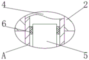
FIG. 2 is an enlarged view taken at A in FIG. 1 according to the present invention;
FIG. 3 is an enlarged view of the invention at B in FIG. 1;
FIG. 4 is an enlarged view of the invention at C of FIG. 1;
fig. 5 is an enlarged view of the invention at D in fig. 1.
In the figure: 1. a housing; 2. a shell cover; 3. an air pump; 4. an air inlet pipe; 5. a connecting pipe; 6. a seal ring; 7. a slide pin; 8. a chute; 9. a support ring; 10. a handle; 11. a cover body; 12. a convex edge; 13. a bump; 14. an air outlet groove; 15. a toothed ring; 16. a support plate; 17. a guide block; 18. a guide groove; 19. a motor; 20. a rotating shaft; 21. a square block; 22. a gear; 23. a square hole; 24. a stopper; 25. cushion blocks; 26. a transformer; 27. and an air outlet.
Detailed Description
The technical solutions in the embodiments of the present invention will be clearly and completely described below with reference to the drawings in the embodiments of the present invention, and it is obvious that the described embodiments are only a part of the embodiments of the present invention, and not all of the embodiments. All other embodiments, which can be derived by a person skilled in the art from the embodiments given herein without making any creative effort, shall fall within the protection scope of the present invention.
Referring to fig. 1-5, an auxiliary heat dissipation device for a transformer comprises a housing 1, a housing cover 2 is connected to the housing 1 through a screw, an air pump 3 is fixedly installed on the housing cover 2, an air inlet pipe 4 of the air pump 3 is slidably connected to the housing cover 2, a connecting pipe 5 is slidably sleeved in the air inlet pipe 4, a sliding pin 7 is welded to the connecting pipe 5, a support ring 9 is connected to the outer side of the air inlet pipe 4 through a screw thread, a cover body 11 is rotatably connected to the outer side of the connecting pipe 5, a convex edge 12 is arranged on the cover body 11, an air outlet groove 14 is formed in the cover body 11, a toothed ring 15 is fixedly sleeved to the outer side of the cover body 11, a support plate 16 is fixedly sleeved to the outer side of the connecting pipe 5, the support plate 16 is in contact with the housing 1, a motor 19 is fixedly installed on the support plate 16, a rotating shaft 20 of the motor 19 is rotatably connected to the support plate 16, a square block 21 is welded to the rotating shaft 20, a gear 22 is slidably sleeved to the outer side of the square block 21, the gear 22 is meshed with the gear ring 15, a cushion block 25 is welded on the shell 1, and a transformer 26 is fixedly arranged on the cushion block 25.
Referring to fig. 2, the outer side of the connecting pipe 5 is fixedly sleeved with a sealing ring 6, and the sealing ring 6 is slidably connected with the air inlet pipe 4. By providing the seal ring 6, the sealing property between the connection pipe 5 and the intake pipe 4 is increased.
Referring to fig. 3, a sliding slot 8 is formed in the side wall of the air inlet pipe 4, and a sliding pin 7 is slidably connected in the sliding slot 8. The slide pin 7 is guided by providing the slide groove 8.
Referring to fig. 3, a handle 10 is welded on the support ring 9, and the support ring 9 contacts with the sliding pin 7. The support ring 9 is made easy to turn by the provision of a handle 10.
Referring to fig. 4, the convex edge 12 is provided with a bump 13, a bump 13 and a cover 11. By providing the projections 13, the friction between the cover 11 and the collar 12 is reduced.
Referring to fig. 1, a guide block 17 is welded on the support plate 16, a guide groove 18 is formed on the side wall of the housing 1, and the guide block 17 is slidably connected in the guide groove 18. The guide block 17 and the guide groove 18 are arranged to cooperate with each other to guide the movement of the support plate 16.
Referring to fig. 5, a square hole 23 is formed on the gear 22, and the square block 21 can be connected to the inside of the square hole 23. By providing the square hole 23, the square block 21 can drive the gear 22 to rotate.
Referring to fig. 5, a stopper 24 is connected to the square block 21 through a screw, the stopper 24 contacts with the gear 22, and the gear 22 contacts with the rotating shaft 20. The gear 22 is limited by the provision of a stop 24.
Referring to fig. 1, there are four spacers 25, and the four spacers 25 are uniformly distributed on the housing 1. The transformer 26 is supported by the spacers 25.
Referring to fig. 1, the housing 1 is provided with a plurality of air outlets 27, and the plurality of air outlets 27 are uniformly distributed on the sidewall of the housing 1. By providing the air outlet 27, air in the housing 1 can be exhausted.
The specific implementation process of the invention is as follows: when the air pump is used, the height of the cover body 11 is adjusted by the height of the transformer 26, the support ring 9 is rotated by the handle 10, the support ring 9 rotates and the air inlet pipe 4 makes a threaded motion, so that the support ring 9 moves on the air inlet pipe 4, the support ring 9 moves to drive the sliding pin 7 to slide in the sliding groove 8, the sliding pin 7 moves to drive the connecting pipe 5 to move, the connecting pipe 5 drives the convex edge 12 to move, the convex edge 12 drives the convex edge 13 to move, the convex edge 13 drives the cover body 11 to move, the connecting pipe 5 can be driven to move relative to the air inlet pipe 4 by rotating the support ring 9 and the air inlet pipe 4 to make a threaded motion, the connecting pipe 5 stretches in the air inlet pipe 4, so that the extending length of the connecting pipe 5 can be adjusted, the distance between the cover body 11 and the transformer 26 is adjusted, the cooling efficiency is ensured, then the air pump 3 is started, the air inlet pipe 4 is led into the cover body 11 through the connecting pipe 5, and the air in the cover body 11 is blown to the transformer 26 through the air outlet groove 14, starting motor 19, pivot 20 rotate and drive square 21 and rotate, and square 21 drives gear 22 and rotates, and gear 22 drives ring gear 15 and rotates, and ring gear 15 drives the cover body 11 and rotates, and the cover body 11 rotates and makes gas outlet groove 14 to blow more evenly to transformer 26, avoids transformer 26 local difference in temperature too big, leads to transformer 26 life to reduce.
Although embodiments of the present invention have been shown and described, it will be appreciated by those skilled in the art that changes, modifications, substitutions and alterations can be made in these embodiments without departing from the principles and spirit of the invention, the scope of which is defined in the appended claims and their equivalents.
Claims (10)
1. An auxiliary heat sink for a transformer, comprising a housing (1), characterized in that: the shell cover is characterized in that the shell cover (2) is connected onto the shell (1) through screws, an air pump (3) is fixedly mounted on the shell cover (2), an air inlet pipe (4) of the air pump (3) is connected with the shell cover (2) in a sliding manner, a connecting pipe (5) is sleeved in the air inlet pipe (4) in the sliding manner, a sliding pin (7) is welded onto the connecting pipe (5), the outer side of the air inlet pipe (4) is connected with a support ring (9) through threads, the outer side of the connecting pipe (5) is rotatably connected with a cover body (11), a convex edge (12) is arranged on the cover body (11), an air outlet groove (14) is formed in the cover body (11), a toothed ring (15) is fixedly sleeved on the outer side of the cover body (11), a support plate (16) is fixedly sleeved on the outer side of the connecting pipe (5), the support plate (16) is contacted with the shell (1), and a motor (19) is fixedly mounted on the support plate (16), the utility model discloses a motor, including casing (1), pivot (20) and backup pad (16) of motor (19) rotate to be connected, the welding has square piece (21) in pivot (20), gear (22) have been cup jointed in the outside slip of square piece (21), gear (22) and ring gear (15) meshing, the welding has cushion (25) on casing (1), fixed mounting has transformer (26) on cushion (25).
2. The auxiliary heat sink for transformer according to claim 1, wherein: the outer side of the connecting pipe (5) is fixedly sleeved with a sealing ring (6), and the sealing ring (6) is connected with the air inlet pipe (4) in a sliding mode.
3. The auxiliary heat sink for transformer according to claim 1, wherein: the side wall of the air inlet pipe (4) is provided with a sliding chute (8), and a sliding pin (7) is connected in the sliding chute (8) in a sliding mode.
4. The auxiliary heat sink for transformer according to claim 1, wherein: the handle (10) is welded on the support ring (9), and the support ring (9) is in contact with the sliding pin (7).
5. The auxiliary heat sink for transformer according to claim 1, wherein: the convex edge (12) is provided with a convex block (13), and the convex block (13) and the cover body (11) are arranged on the cover body.
6. The auxiliary heat sink for transformer according to claim 1, wherein: the welding has guide block (17) on backup pad (16), guide slot (18) have been seted up to the lateral wall of casing (1), sliding connection has guide block (17) in guide slot (18).
7. The auxiliary heat sink for transformer according to claim 1, wherein: a square hole (23) is formed in the gear (22), and a square block (21) can be connected in the square hole (23).
8. The auxiliary heat sink for transformer according to claim 1, wherein: the square block (21) is connected with a stop block (24) through a screw, the stop block (24) is in contact with a gear (22), and the gear (22) is in contact with a rotating shaft (20).
9. The auxiliary heat sink for transformer according to claim 1, wherein: the number of the cushion blocks (25) is four, and the four cushion blocks (25) are uniformly distributed on the shell (1).
10. The auxiliary heat sink for transformer according to claim 1, wherein: a plurality of air outlet holes (27) are formed in the shell (1), and the air outlet holes (27) are uniformly distributed in the side wall of the shell (1).
Priority Applications (1)
| Application Number | Priority Date | Filing Date | Title |
|---|---|---|---|
| CN202110976758.9A CN113838642B (en) | 2021-08-24 | 2021-08-24 | Auxiliary heat dissipation device for transformer |
Applications Claiming Priority (1)
| Application Number | Priority Date | Filing Date | Title |
|---|---|---|---|
| CN202110976758.9A CN113838642B (en) | 2021-08-24 | 2021-08-24 | Auxiliary heat dissipation device for transformer |
Publications (2)
| Publication Number | Publication Date |
|---|---|
| CN113838642A true CN113838642A (en) | 2021-12-24 |
| CN113838642B CN113838642B (en) | 2023-10-20 |
Family
ID=78961131
Family Applications (1)
| Application Number | Title | Priority Date | Filing Date |
|---|---|---|---|
| CN202110976758.9A Active CN113838642B (en) | 2021-08-24 | 2021-08-24 | Auxiliary heat dissipation device for transformer |
Country Status (1)
| Country | Link |
|---|---|
| CN (1) | CN113838642B (en) |
Citations (11)
| Publication number | Priority date | Publication date | Assignee | Title |
|---|---|---|---|---|
| CN104992815A (en) * | 2015-08-03 | 2015-10-21 | 王磊 | Heat-dissipation dry type transformer device |
| CN105119498A (en) * | 2015-09-14 | 2015-12-02 | 永济新时速电机电器有限责任公司 | Rail vehicle auxiliary convertor system and rail vehicle |
| CN209374228U (en) * | 2018-12-21 | 2019-09-10 | 天津市元和华铁电气设备有限公司 | A kind of railway isolating transformer radiator |
| CN110517851A (en) * | 2019-09-24 | 2019-11-29 | 国网山东省电力公司莱州市供电公司 | A kind of main transformer cooling device |
| CN112002534A (en) * | 2020-08-20 | 2020-11-27 | 国网山东省电力公司龙口市供电公司 | Winding device for transformer core |
| CN112350247A (en) * | 2020-11-12 | 2021-02-09 | 佛山市高明欧一电子制造有限公司 | Controller pencil protector |
| CN212632197U (en) * | 2020-06-29 | 2021-03-02 | 重庆鑫协环保设备有限公司 | Complete system equipment for purifying and treating waste gas and dust in paint spray booth |
| CN212967311U (en) * | 2020-09-08 | 2021-04-13 | 瑞特希(天津)电气设备科技有限公司 | Waterproof heat dissipation shell of transformer |
| CN213634387U (en) * | 2020-11-05 | 2021-07-06 | 漳州职业技术学院 | Multitask control computer switching device |
| CN216423175U (en) * | 2021-07-28 | 2022-05-03 | 惠州市鼎川智能科技有限公司 | Cooling device for plastic parts |
| CN216871714U (en) * | 2019-06-17 | 2022-07-01 | 李钟淳 | Cooling device for die transformer |
-
2021
- 2021-08-24 CN CN202110976758.9A patent/CN113838642B/en active Active
Patent Citations (11)
| Publication number | Priority date | Publication date | Assignee | Title |
|---|---|---|---|---|
| CN104992815A (en) * | 2015-08-03 | 2015-10-21 | 王磊 | Heat-dissipation dry type transformer device |
| CN105119498A (en) * | 2015-09-14 | 2015-12-02 | 永济新时速电机电器有限责任公司 | Rail vehicle auxiliary convertor system and rail vehicle |
| CN209374228U (en) * | 2018-12-21 | 2019-09-10 | 天津市元和华铁电气设备有限公司 | A kind of railway isolating transformer radiator |
| CN216871714U (en) * | 2019-06-17 | 2022-07-01 | 李钟淳 | Cooling device for die transformer |
| CN110517851A (en) * | 2019-09-24 | 2019-11-29 | 国网山东省电力公司莱州市供电公司 | A kind of main transformer cooling device |
| CN212632197U (en) * | 2020-06-29 | 2021-03-02 | 重庆鑫协环保设备有限公司 | Complete system equipment for purifying and treating waste gas and dust in paint spray booth |
| CN112002534A (en) * | 2020-08-20 | 2020-11-27 | 国网山东省电力公司龙口市供电公司 | Winding device for transformer core |
| CN212967311U (en) * | 2020-09-08 | 2021-04-13 | 瑞特希(天津)电气设备科技有限公司 | Waterproof heat dissipation shell of transformer |
| CN213634387U (en) * | 2020-11-05 | 2021-07-06 | 漳州职业技术学院 | Multitask control computer switching device |
| CN112350247A (en) * | 2020-11-12 | 2021-02-09 | 佛山市高明欧一电子制造有限公司 | Controller pencil protector |
| CN216423175U (en) * | 2021-07-28 | 2022-05-03 | 惠州市鼎川智能科技有限公司 | Cooling device for plastic parts |
Also Published As
| Publication number | Publication date |
|---|---|
| CN113838642B (en) | 2023-10-20 |
Similar Documents
| Publication | Publication Date | Title |
|---|---|---|
| CN109274220A (en) | A kind of high efficiency and heat radiation motor | |
| CN115148464B (en) | Energy-saving dry-type transformer | |
| CN113838642A (en) | Auxiliary heat dissipation device for transformer | |
| CN112408509A (en) | High-efficient convenient chemical industry reaction heat dissipation explosion-proof equipment | |
| CN201733174U (en) | Electrical machine | |
| CN207815432U (en) | A kind of telescopic range hood | |
| CN210790876U (en) | Current transformer is with dismouting auxiliary device | |
| CN208691052U (en) | A kind of cleaning type is from heat dissipation refrigerator motor | |
| CN217523125U (en) | Safety monitoring device is used in power plant with heat dissipation function | |
| CN216047116U (en) | Household intelligent lighting energy-saving lamp based on 5G | |
| CN215067779U (en) | Industrial internet controller convenient to installation | |
| CN211089477U (en) | Adapter with good heat dissipation effect | |
| CN212136162U (en) | Outdoor electronic transformer with good heat dissipation effect | |
| CN207280064U (en) | A kind of Electronic Components Manufacturing cooling device | |
| CN115631925A (en) | Inductor shock-absorbing structure | |
| CN208907582U (en) | A kind of LED projector lamp | |
| CN210348381U (en) | Automatic cooling device of computer | |
| CN209526923U (en) | A kind of New LED driving power | |
| CN210628038U (en) | External current transformer for transformer | |
| CN208997915U (en) | A kind of rotating LED parlor lamp easy to use | |
| CN212643103U (en) | Spiral air compressor | |
| CN217405237U (en) | Energy-saving operation device of transformer | |
| CN213841157U (en) | Mounting structure convenient to central air conditioning maintenance is used | |
| CN218069557U (en) | Dry-type transformer with fan mounting seat | |
| CN213638556U (en) | No-load current-limiting power-saving device |
Legal Events
| Date | Code | Title | Description |
|---|---|---|---|
| PB01 | Publication | ||
| PB01 | Publication | ||
| SE01 | Entry into force of request for substantive examination | ||
| SE01 | Entry into force of request for substantive examination | ||
| GR01 | Patent grant | ||
| GR01 | Patent grant |