CN113823507B - Capacitor assembly with high heat dissipation performance - Google Patents
Capacitor assembly with high heat dissipation performance Download PDFInfo
- Publication number
- CN113823507B CN113823507B CN202111228443.2A CN202111228443A CN113823507B CN 113823507 B CN113823507 B CN 113823507B CN 202111228443 A CN202111228443 A CN 202111228443A CN 113823507 B CN113823507 B CN 113823507B
- Authority
- CN
- China
- Prior art keywords
- control module
- plate
- capacitor
- heat dissipation
- discharging
- Prior art date
- Legal status (The legal status is an assumption and is not a legal conclusion. Google has not performed a legal analysis and makes no representation as to the accuracy of the status listed.)
- Active
Links
- 239000003990 capacitor Substances 0.000 title claims abstract description 88
- 230000017525 heat dissipation Effects 0.000 title claims abstract description 31
- 238000007599 discharging Methods 0.000 claims description 30
- 238000001816 cooling Methods 0.000 claims description 16
- 238000009423 ventilation Methods 0.000 claims description 3
- 238000007664 blowing Methods 0.000 claims 1
- 238000010586 diagram Methods 0.000 description 16
- 239000000463 material Substances 0.000 description 3
- 239000004020 conductor Substances 0.000 description 2
- 239000000428 dust Substances 0.000 description 2
- 230000005611 electricity Effects 0.000 description 2
- 230000006835 compression Effects 0.000 description 1
- 238000007906 compression Methods 0.000 description 1
- 230000000694 effects Effects 0.000 description 1
- 239000000284 extract Substances 0.000 description 1
- 238000009434 installation Methods 0.000 description 1
- 238000000034 method Methods 0.000 description 1
- 238000003878 thermal aging Methods 0.000 description 1
Images


Classifications
-
- H—ELECTRICITY
- H01—ELECTRIC ELEMENTS
- H01G—CAPACITORS; CAPACITORS, RECTIFIERS, DETECTORS, SWITCHING DEVICES, LIGHT-SENSITIVE OR TEMPERATURE-SENSITIVE DEVICES OF THE ELECTROLYTIC TYPE
- H01G2/00—Details of capacitors not covered by a single one of groups H01G4/00-H01G11/00
- H01G2/08—Cooling arrangements; Heating arrangements; Ventilating arrangements
-
- H—ELECTRICITY
- H01—ELECTRIC ELEMENTS
- H01G—CAPACITORS; CAPACITORS, RECTIFIERS, DETECTORS, SWITCHING DEVICES, LIGHT-SENSITIVE OR TEMPERATURE-SENSITIVE DEVICES OF THE ELECTROLYTIC TYPE
- H01G2/00—Details of capacitors not covered by a single one of groups H01G4/00-H01G11/00
- H01G2/02—Mountings
-
- H—ELECTRICITY
- H01—ELECTRIC ELEMENTS
- H01G—CAPACITORS; CAPACITORS, RECTIFIERS, DETECTORS, SWITCHING DEVICES, LIGHT-SENSITIVE OR TEMPERATURE-SENSITIVE DEVICES OF THE ELECTROLYTIC TYPE
- H01G2/00—Details of capacitors not covered by a single one of groups H01G4/00-H01G11/00
- H01G2/10—Housing; Encapsulation
- H01G2/106—Fixing the capacitor in a housing
-
- H—ELECTRICITY
- H01—ELECTRIC ELEMENTS
- H01G—CAPACITORS; CAPACITORS, RECTIFIERS, DETECTORS, SWITCHING DEVICES, LIGHT-SENSITIVE OR TEMPERATURE-SENSITIVE DEVICES OF THE ELECTROLYTIC TYPE
- H01G2/00—Details of capacitors not covered by a single one of groups H01G4/00-H01G11/00
- H01G2/14—Protection against electric or thermal overload
- H01G2/18—Protection against electric or thermal overload with breakable contacts
-
- Y—GENERAL TAGGING OF NEW TECHNOLOGICAL DEVELOPMENTS; GENERAL TAGGING OF CROSS-SECTIONAL TECHNOLOGIES SPANNING OVER SEVERAL SECTIONS OF THE IPC; TECHNICAL SUBJECTS COVERED BY FORMER USPC CROSS-REFERENCE ART COLLECTIONS [XRACs] AND DIGESTS
- Y02—TECHNOLOGIES OR APPLICATIONS FOR MITIGATION OR ADAPTATION AGAINST CLIMATE CHANGE
- Y02E—REDUCTION OF GREENHOUSE GAS [GHG] EMISSIONS, RELATED TO ENERGY GENERATION, TRANSMISSION OR DISTRIBUTION
- Y02E40/00—Technologies for an efficient electrical power generation, transmission or distribution
- Y02E40/30—Reactive power compensation
Landscapes
- Engineering & Computer Science (AREA)
- Power Engineering (AREA)
- Microelectronics & Electronic Packaging (AREA)
- Fixed Capacitors And Capacitor Manufacturing Machines (AREA)
- Cooling Or The Like Of Electrical Apparatus (AREA)
Abstract
本发明涉及一种电容器,尤其涉及一种具有高散热性能的电容器组件。本发明的技术问题是:提供一种提高工作效率,且能够对电容器进行准确定位的具有高散热性能的电容器组件。本发明的技术实施方案为:一种具有高散热性能的电容器组件,包括:放料框和控制箱等,放料框上设有控制箱,控制箱内安装有蓄电池、电源模块和控制模块,蓄电池为整个具有高散热性能的电容器组件供电,蓄电池的输出端与电源模块通过电性连接,电源模块上通过线路连接有电源总开关,电源模块与控制模块通过电性连接;控制模块上连接有DS1302时钟电路和24C02电路。第二电动推杆伸缩杆带动定位板向后移动与电容器接触,进而对电容器进行定位。
The invention relates to a capacitor, in particular to a capacitor component with high heat dissipation performance. The technical problem of the present invention is to provide a capacitor assembly with high heat dissipation performance that improves working efficiency and can accurately position the capacitor. The technical embodiment of the present invention is: a capacitor assembly with high heat dissipation performance, including: a discharge frame and a control box, etc., a control box is arranged on the discharge frame, and a battery, a power module and a control module are installed in the control box. The battery supplies power to the entire capacitor assembly with high heat dissipation performance. The output terminal of the battery is electrically connected to the power module. DS1302 clock circuit and 24C02 circuit. The telescopic rod of the second electric push rod drives the positioning plate to move backward to contact with the capacitor, and then the capacitor is positioned.
Description
技术领域technical field
本发明涉及一种电容器,尤其涉及一种具有高散热性能的电容器组件。The invention relates to a capacitor, in particular to a capacitor component with high heat dissipation performance.
背景技术Background technique
目前,市面上有着各种各样的电容器机箱产品,而电容器内部摆放了太多的电容,电容器在长期处于高温下运行的时候,内部热量无法及时散发出去导致发生热老化现象,从而严重影响电容器实用寿命。At present, there are various capacitor chassis products on the market, and too many capacitors are placed inside the capacitor. When the capacitor is operated at high temperature for a long time, the internal heat cannot be dissipated in time, resulting in thermal aging, which seriously affects the Capacitor practical life.
中国专利号CN208548265U提出了一种高散热电容器,通过在装置的底部设有散热底座板,可以更好的对装置进行散热,而以上专利中,对于电容器在使用时的安装并没有得到完善,因为电容器是比较脆弱的装置,所以在安装时较为麻烦,需要工作人员会异常小心,从而降低工作效率,且不能对电容器准确定位,容易导致电容器与导电体产生偏离。Chinese Patent No. CN208548265U proposes a high heat dissipation capacitor. By providing a heat dissipation base plate at the bottom of the device, the device can be better radiated heat. However, in the above patents, the installation of the capacitor during use has not been perfected, because Capacitors are relatively fragile devices, so it is more troublesome to install, requiring the staff to be extremely careful, thereby reducing work efficiency, and the capacitor cannot be positioned accurately, which may easily lead to deviation between the capacitor and the conductor.
因此,鉴于上述问题提供一种提高工作效率,且能够对电容器进行准确定位的具有高散热性能的电容器组件。Therefore, in view of the above problems, a capacitor assembly with high heat dissipation performance can be provided to improve the working efficiency and accurately position the capacitor.
发明内容Contents of the invention
为了克服电容器是比较脆弱的装置,需要工作人员会异常小心,从而降低工作效率,且不能对电容器准确定位,容易导致电容器与导电体产生偏离的缺点,本发明的技术问题是:提供一种提高工作效率,且能够对电容器进行准确定位的具有高散热性能的电容器组件。In order to overcome the shortcomings that the capacitor is a relatively fragile device, the staff must be extremely careful, thereby reducing the work efficiency, and the capacitor cannot be positioned accurately, which may easily lead to the deviation between the capacitor and the conductor. The technical problem of the present invention is: to provide an improved Capacitor components with high heat dissipation performance, high work efficiency, and accurate positioning of capacitors.
本发明的技术实施方案为:一种具有高散热性能的电容器组件,包括有放料框、电容器、启动键、控制箱、散热板、放料机构和降温机构,放料框上设有控制箱,控制箱内安装有蓄电池、电源模块和控制模块,蓄电池为整个具有高散热性能的电容器组件供电,蓄电池的输出端与电源模块通过电性连接,电源模块上通过线路连接有电源总开关,电源模块与控制模块通过电性连接;控制模块上连接有DS1302时钟电路和24C02电路,控制箱一侧设有启动键,启动键与控制模块通过电性连接,放料框上对称设有散热板,放料框内侧设有放料机构,放料机构部件上放置有电容器,放料框内底部设有降温机构。The technical embodiment of the present invention is: a capacitor assembly with high heat dissipation performance, including a discharge frame, a capacitor, a start key, a control box, a heat dissipation plate, a discharge mechanism and a cooling mechanism, and a control box is arranged on the discharge frame , the control box is equipped with a battery, a power module and a control module, the battery supplies power to the entire capacitor assembly with high heat dissipation performance, the output terminal of the battery is electrically connected to the power module, and the power module is connected to the main power switch through a line, the power supply The module and the control module are electrically connected; the control module is connected with a DS1302 clock circuit and a 24C02 circuit. There is a start button on one side of the control box, and the start button is electrically connected with the control module. The cooling plate is symmetrically arranged on the discharge frame. A discharge mechanism is arranged inside the discharge frame, capacitors are placed on the components of the discharge mechanism, and a cooling mechanism is provided at the bottom of the discharge frame.
优选地,放料机构包括有第一滑杆、第一电动推杆、放料板和第一距离传感器,放料框内底部两侧均对称设有第一滑杆,放料框内底部中间设有第一电动推杆,第一电动推杆与控制模块通过继电器控制模块连接,第一滑杆之间滑动式设有放料板,放料板底部中间与第一电动推杆伸缩杆顶部连接,电容器放置在放料板上,放料板中间设有第一距离传感器,第一距离传感器与控制模块通过电性连接。Preferably, the discharging mechanism includes a first sliding rod, a first electric push rod, a discharging plate and a first distance sensor, and the first sliding rods are symmetrically arranged on both sides of the bottom of the discharging frame, and the middle of the bottom of the discharging frame There is a first electric push rod, and the first electric push rod is connected to the control module through the relay control module. A discharge plate is slid between the first slide rods, and the middle of the bottom of the discharge plate is connected to the top of the telescopic rod of the first electric push rod. connection, the capacitor is placed on the discharge plate, a first distance sensor is arranged in the middle of the discharge plate, and the first distance sensor is electrically connected to the control module.
优选地,降温机构包括有气泵、电磁阀、伸缩管、风扇和温度传感器,放料框内底部设有气泵,气泵与控制模块通过继电器控制模块连接,气泵一侧穿过放料框上设有电磁阀,电磁阀与控制模块通过继电器控制模块连接,气泵顶部设有伸缩管,伸缩管与放料板连接,放料框内侧壁设有风扇,风扇一侧设有温度传感器,温度传感器与控制模块通过电性连接。Preferably, the cooling mechanism includes an air pump, a solenoid valve, a telescopic tube, a fan, and a temperature sensor. An air pump is provided at the bottom of the discharge frame, and the air pump is connected to the control module through a relay control module. One side of the air pump passes through the discharge frame. Solenoid valve, the solenoid valve is connected with the control module through the relay control module, there is a telescopic tube on the top of the air pump, the telescopic tube is connected to the discharge plate, a fan is provided on the inner wall of the discharge frame, a temperature sensor is provided on one side of the fan, and the temperature sensor is connected to the control panel. The modules are electrically connected.
优选地,还包括有定位机构,定位机构包括有第二电动推杆、定位板、压力传感器和第二距离传感器,放料框内侧壁对称设有第二电动推杆,第二电动推杆与控制模块通过继电器控制模块连接,第二电动推杆伸缩杆之间设有定位板,定位板上设有压力传感器,压力传感器与控制模块通过电性连接,定位板上设有第二距离传感器,第二距离传感器与控制模块通过电性连接。Preferably, a positioning mechanism is also included. The positioning mechanism includes a second electric push rod, a positioning plate, a pressure sensor and a second distance sensor. The inner wall of the discharge frame is symmetrically provided with a second electric push rod. The control module is connected through the relay control module, a positioning plate is provided between the telescopic rods of the second electric push rod, a pressure sensor is provided on the positioning board, the pressure sensor is electrically connected to the control module, and a second distance sensor is provided on the positioning board. The second distance sensor is electrically connected to the control module.
优选地,还包括有进料机构,进料机构包括有活动板、第三距离传感器、滑轨和第三电动推杆,放料框顶部设有滑轨,滑轨内侧滑动式设有活动板,活动板一侧设有第三距离传感器,第三距离传感器与控制模块通过电性连接,滑轨上对称设有第三电动推杆,第三电动推杆与控制模块通过继电器控制模块连接,第三电动推杆伸缩杆均与活动板连接。Preferably, it also includes a feeding mechanism, the feeding mechanism includes a movable plate, a third distance sensor, a slide rail and a third electric push rod, a slide rail is provided on the top of the discharge frame, and a movable plate is provided slidingly inside the slide rail , a third distance sensor is provided on one side of the movable plate, the third distance sensor is electrically connected to the control module, a third electric push rod is symmetrically provided on the slide rail, and the third electric push rod is connected to the control module through a relay control module, The telescopic rods of the third electric push rod are all connected with the movable plate.
优选地,还包括有卡紧机构,卡紧机构包括有弹性绳、固定板、第二滑杆、第一弹簧、滑动板、活动轴、卡紧块和第二弹簧,放料板顶部设有固定板,固定板一侧对称设有第二滑杆,第二滑杆之间滑动式设有滑动板,滑动板与活动板之间连接有弹性绳,滑动板与固定板之间对称连接有第一弹簧,第一弹簧均套在同侧的第二滑杆上,滑动板上对称转动式设有活动轴,活动轴之间连接有卡紧块,卡紧块与固定板之间对称连接有第二弹簧。Preferably, a clamping mechanism is also included. The clamping mechanism includes an elastic rope, a fixed plate, a second slide bar, a first spring, a sliding plate, a movable shaft, a clamping block and a second spring. The fixed plate is symmetrically provided with a second sliding bar on one side of the fixed plate, and a sliding plate is slidable between the second sliding bars. An elastic rope is connected between the sliding plate and the movable plate, and a symmetrical connection is made between the sliding plate and the fixed plate. The first spring and the first spring are both sleeved on the second sliding rod on the same side. The sliding plate is symmetrically rotated and provided with movable shafts, and clamping blocks are connected between the movable shafts, and the clamping blocks are symmetrically connected to the fixed plate. There is a second spring.
优选地,还包括有接线机构,接线机构包括有接线块、U形杆、第三弹簧和接触块,活动板顶部对称螺纹式连接有接线块,接线块上均对称设有U形杆,U形杆上内侧均滑动式设有接触块,接触块均与同侧的U形杆之间连接有第三弹簧。Preferably, it also includes a wiring mechanism. The wiring mechanism includes a wiring block, a U-shaped bar, a third spring and a contact block. The top of the movable plate is connected to the wiring block in a symmetrical threaded manner, and the wiring blocks are symmetrically provided with U-shaped bars. The upper and inner sides of the shaped rods are all slidingly provided with contact blocks, and the third springs are connected between the contact blocks and the U-shaped rods on the same side.
优选地,散热板上开有多个用于散热通风的散热孔。Preferably, a plurality of heat dissipation holes for heat dissipation and ventilation are opened on the heat dissipation plate.
与现有技术相比,本发明具有如下优点:1、第二电动推杆伸缩杆带动定位板向后移动与电容器接触,进而对电容器进行定位;Compared with the prior art, the present invention has the following advantages: 1. The telescopic rod of the second electric push rod drives the positioning plate to move backwards to contact the capacitor, thereby positioning the capacitor;
2、第三电动推杆伸缩杆带动活动板复位,放料框被关闭,如此可避免灰尘或者杂物掉进放料框内;2. The telescopic rod of the third electric push rod drives the movable plate to reset, and the discharge frame is closed, so as to prevent dust or sundries from falling into the discharge frame;
3、在第二弹簧和第一弹簧的作用下,滑动板和卡紧块卡紧电容器,如此可以更高的固定住电容器,避免电容器滑动被磕坏;3. Under the action of the second spring and the first spring, the sliding plate and the clamping block clamp the capacitor, so that the capacitor can be fixed at a higher level to prevent the capacitor from sliding and being damaged;
4、需要使用电容器时,转动接线块,使得接线块与电容器正负级接触,进行使用,不需要使用电容器时,反转接线块,使得接线块与电容器分离,如此可防止不需要使用电容器时,电容器持续导电,进而消耗电容器的使用寿命。4. When you need to use a capacitor, turn the wiring block so that the wiring block is in contact with the positive and negative stages of the capacitor for use. When you do not need to use the capacitor, reverse the wiring block to separate the wiring block from the capacitor. , the capacitor continues to conduct electricity, thereby consuming the service life of the capacitor.
附图说明Description of drawings
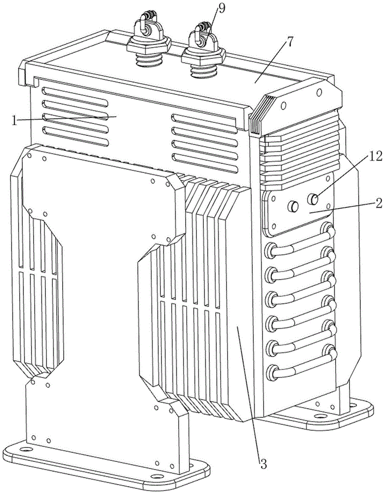
图1为本发明的立体结构示意图。Fig. 1 is a schematic diagram of the three-dimensional structure of the present invention.
图2为本发明的第一视角立体结构示意图。Fig. 2 is a schematic diagram of the stereoscopic structure of the present invention at a first viewing angle.
图3为本发明的第二视角部分立体结构示意图。Fig. 3 is a schematic diagram of a partial three-dimensional structure of a second viewing angle of the present invention.
图4为本发明放料机构的第一种部分立体结构示意图。Fig. 4 is a schematic diagram of the first partial three-dimensional structure of the discharging mechanism of the present invention.
图5为本发明放料机构的第二种部分立体结构示意图。Fig. 5 is a schematic diagram of the second partial three-dimensional structure of the discharging mechanism of the present invention.
图6为本发明降温机构的立体结构示意图。Fig. 6 is a schematic perspective view of the three-dimensional structure of the cooling mechanism of the present invention.
图7为本发明定位机构的第一种部分立体结构示意图。Fig. 7 is a schematic diagram of the first partial three-dimensional structure of the positioning mechanism of the present invention.
图8为本发明定位机构的第二种部分立体结构示意图。Fig. 8 is a schematic diagram of the second partial three-dimensional structure of the positioning mechanism of the present invention.
图9为本发明进料机构的第一种部分立体结构示意图。Fig. 9 is a schematic diagram of the first partial three-dimensional structure of the feeding mechanism of the present invention.
图10为本发明进料机构的第二种部分立体结构示意图。Fig. 10 is a schematic diagram of the second partial three-dimensional structure of the feeding mechanism of the present invention.
图11为本发明卡紧机构的第一种部分立体结构示意图。Fig. 11 is a schematic diagram of the first partial three-dimensional structure of the clamping mechanism of the present invention.
图12为本发明卡紧机构的第二种立体结构示意图。Fig. 12 is a schematic diagram of the second three-dimensional structure of the clamping mechanism of the present invention.
图13为本发明卡紧机构的第三种部分立体结构示意图。Fig. 13 is a schematic diagram of a third partial three-dimensional structure of the clamping mechanism of the present invention.
图14为本发明接线机构的第一种部分立体结构示意图。Fig. 14 is a schematic diagram of the first partial three-dimensional structure of the wiring mechanism of the present invention.
图15为本发明接线机构的第二种部分立体结构示意图。Fig. 15 is a schematic diagram of the second partial three-dimensional structure of the wiring mechanism of the present invention.
图16为本发明的电路框图。Fig. 16 is a circuit block diagram of the present invention.
图17为本发明的电路原理图。Fig. 17 is a schematic circuit diagram of the present invention.
附图中各零部件的标记如下:1、放料框,11、电容器,12、启动键,2、控制箱,3、散热板,4、放料机构,41、第一滑杆,42、第一电动推杆,43、放料板,44、第一距离传感器,5、降温机构,51、气泵,52、电磁阀,53、伸缩管,54、风扇,55、温度传感器,6、定位机构,61、第二电动推杆,62、定位板,63、压力传感器,64、第二距离传感器,7、进料机构,71、活动板,72、第三距离传感器,73、滑轨,74、第三电动推杆,8、卡紧机构,81、弹性绳,82、固定板,83、第二滑杆,84、第一弹簧,85、滑动板,86、活动轴,87、卡紧块,88、第二弹簧,9、接线机构,91、接线块,92、U形杆,93、第三弹簧,94、接触块。The marks of each part in the accompanying drawings are as follows: 1, material discharging frame, 11, capacitor, 12, start key, 2, control box, 3, cooling plate, 4, material discharging mechanism, 41, the first slide bar, 42, The first electric push rod, 43, the discharge plate, 44, the first distance sensor, 5, the cooling mechanism, 51, the air pump, 52, the solenoid valve, 53, the telescopic tube, 54, the fan, 55, the temperature sensor, 6, the positioning Mechanism, 61, the second electric push rod, 62, positioning plate, 63, pressure sensor, 64, the second distance sensor, 7, feeding mechanism, 71, movable plate, 72, the third distance sensor, 73, slide rail, 74, the third electric push rod, 8, clamping mechanism, 81, elastic rope, 82, fixed plate, 83, the second slide bar, 84, the first spring, 85, sliding plate, 86, movable shaft, 87, card Tight block, 88, the second spring, 9, wiring mechanism, 91, wiring block, 92, U-shaped bar, 93, the 3rd spring, 94, contact block.
具体实施方式Detailed ways
下面结合附图和实施例对本发明作进一步的说明。The present invention will be further described below in conjunction with the accompanying drawings and embodiments.
实施例1Example 1
一种具有高散热性能的电容器组件,如图1-17所示,包括有放料框1、电容器11、启动键12、控制箱2、散热板3、放料机构4和降温机构5,放料框1上部右侧设有控制箱2,控制箱2内安装有蓄电池、电源模块和控制模块,蓄电池为整个具有高散热性能的电容器组件供电,蓄电池的输出端与电源模块通过电性连接,电源模块上通过线路连接有电源总开关,电源模块与控制模块通过电性连接;控制模块上连接有DS1302时钟电路和24C02电路,控制箱2右侧设有启动键12,启动键12与控制模块通过电性连接,放料框1前后对称设有散热板3,散热板3上开有多个用于散热通风的散热孔,放料框1内侧设有放料机构4,放料机构4部件放置有电容器11,放料框1内底部设有降温机构5。A capacitor assembly with high heat dissipation performance, as shown in Figure 1-17, includes a discharge frame 1, a
放料机构4包括有第一滑杆41、第一电动推杆42、放料板43和第一距离传感器44,放料框1内底部左右两侧均前后对称设有第一滑杆41,放料框1内底部中间设有第一电动推杆42,第一电动推杆42与控制模块通过继电器控制模块连接,第一滑杆41之间滑动式设有放料板43,放料板43底部中间与第一电动推杆42伸缩杆顶部连接,电容器11放置在放料板43上,放料板43中间设有第一距离传感器44,第一距离传感器44与控制模块通过电性连接。The
降温机构5包括有气泵51、电磁阀52、伸缩管53、风扇54和温度传感器55,放料框1内底部左侧设有气泵51,气泵51与控制模块通过继电器控制模块连接,气泵51左侧穿过放料框1上设有电磁阀52,电磁阀52与控制模块通过继电器控制模块连接,气泵51顶部设有伸缩管53,伸缩管53上侧与放料板43连接,放料框1内前壁左侧设有风扇54,风扇54后侧设有温度传感器55,温度传感器55与控制模块通过电性连接。The
当人们需要对电容器进行散热时,可以使用本装置,首先人们按下电源总开关将本设备上电,随后按下启动键12,控制模块控制第一电动推杆42伸缩杆伸长1秒后停止运行,第一电动推杆42伸缩杆带动放料板43向上移动,伸缩管53被拉伸,此时人们将电容器11放在放料板43上,电容器11与第一距离传感器44接触,第一距离传感器44检测到与电容器11之间的距离达到预设值,控制模块控制第一电动推杆42伸缩杆收缩1秒后关闭,第一电动推杆42伸缩杆带动放料板43复位,放料板43带动电容器11向下移动,伸缩管53随之复位;当温度传感器55检测到放料框1内的温度高于预设值时,控制模块控制电磁阀52打开,同时控制模块还会控制气泵51和风扇54启动,风扇54对电容器11进行散热,气泵51将放料框1内的热气通过伸缩管53抽出,当温度传感器55检测到放料框1内的温度低于预设值时,控制模块控制气泵51、电磁阀52和风扇54关闭;当人们需要取出电容器11时,再次按下启动键12,控制模块控制第一电动推杆42伸缩杆伸长1秒后停止运行,第一电动推杆42伸缩杆带动放料板43和电容器11向上移动,伸缩管53被拉伸,将电容器11取出,电容器11与第一距离传感器44分离,第一距离传感器44检测到与电容器11之间的距离回到初设值,控制模块控制第一电动推杆42伸缩杆收缩1秒后关闭,第一电动推杆42伸缩杆带动放料板43复位,伸缩管53随之复位,不需要使用本设备时,按下电源总开关将本设备断电即可。When people need to dissipate heat from the capacitor, this device can be used. First, people press the main power switch to power on the device, and then press the
还包括有定位机构6,定位机构6包括有第二电动推杆61、定位板62、压力传感器63和第二距离传感器64,放料框1内前壁上下对称设有第二电动推杆61,第二电动推杆61与控制模块通过继电器控制模块连接,第二电动推杆61伸缩杆后侧之间设有定位板62,定位板62上设有压力传感器63,压力传感器63与控制模块通过电性连接,定位板62上设有第二距离传感器64,第二距离传感器64与控制模块通过电性连接。Also includes a
当第一距离传感器44检测到与电容器11之间的距离达到预设值时,控制模块控制第一电动推杆42伸缩杆收缩1秒后关闭,控制模块还会控制第二电动推杆61伸缩杆伸长,第二电动推杆61伸缩杆带动定位板62、压力传感器63和第二距离传感器64向后移动,使得定位板62与电容器11接触,进而对电容器11进行定位,同时压力传感器63与电容器11接触挤压,压力传感器63检测到压力达到预设值,控制模块控制第二电动推杆61伸缩杆停止,当人们取出电容器11时,按下启动键12,控制模块还会控制第二电动推杆61伸缩杆收缩,第二电动推杆61伸缩杆带动定位板62、压力传感器63和第二距离传感器64向前移动与电容器11分离,当第二距离传感器64检测到与电容器11之间的距离达到预设值,控制模块控制第二电动推杆61伸缩杆复位至初始状态后关闭,第二电动推杆61伸缩杆带动定位板62、压力传感器63和第二距离传感器64复位。When the
还包括有进料机构7,进料机构7包括有活动板71、第三距离传感器72、滑轨73和第三电动推杆74,放料框1顶部设有滑轨73,滑轨73内侧滑动式设有活动板71,活动板71右侧设有第三距离传感器72,第三距离传感器72与控制模块通过电性连接,滑轨73前后对称设有第三电动推杆74,第三电动推杆74与控制模块通过继电器控制模块连接,第三电动推杆74伸缩杆均与活动板71连接。Also includes feeding mechanism 7, and feeding mechanism 7 includes
当按下启动键12时,控制模块还会控制第三电动推杆74伸缩杆伸长,第三电动推杆74带动活动板71和第三距离传感器72向右移动,第三距离传感器72与放料框1分离,当第三距离传感器72检测到与放料框1之间的距离达到预设值,控制模块控制第三电动推杆74伸缩杆停止运行,当压力传感器63检测到压力达到预设值,控制模块控制第三电动推杆74伸缩杆收缩后关闭,第三电动推杆74伸缩杆带动活动板71和第三距离传感器72复位,放料框1被关闭,如此可避免灰尘或者杂物掉进放料框1内。When the
还包括有卡紧机构8,卡紧机构8包括有弹性绳81、固定板82、第二滑杆83、第一弹簧84、滑动板85、活动轴86、卡紧块87和第二弹簧88,放料板43顶部右侧设有固定板82,固定板82左下侧前后对称设有第二滑杆83,第二滑杆83之间滑动式设有滑动板85,滑动板85与活动板71之间连接有弹性绳81,滑动板85下部右侧与固定板82之间前后对称连接有第一弹簧84,第一弹簧84均套在同侧的第二滑杆83上,滑动板85上部前后对称转动式设有活动轴86,活动轴86之间连接有卡紧块87,卡紧块87右下侧与固定板82之间前后对称连接有第二弹簧88。Also include
当活动板71向右移动时,活动板71通过弹性绳81带动滑动板85向右移动,滑动板85带动活动轴86和卡紧块87向右移动,第二弹簧88和第一弹簧84被压缩,当活动板71向左移动复位时,弹性绳81被放松,进而在第二弹簧88和第一弹簧84复位的作用下带动滑动板85、活动轴86和卡紧块87复位,使得滑动板85和卡紧块87卡紧电容器11,如此可以更高的固定住电容器11,避免电容器11滑动被磕坏。When the
还包括有接线机构9,接线机构9包括有接线块91、U形杆92、第三弹簧93和接触块94,活动板71顶部左右对称螺纹式连接有接线块91,接线块91上部均前后对称设有U形杆92,U形杆92上部内侧均滑动式设有接触块94,接触块94均与同侧的U形杆92之间连接有第三弹簧93。Also includes a
当需要使用电容器11时,转动接线块91,接线块91带动U形杆92、第三弹簧93和接触块94向下移动,使得接线块91与电容器11正负级接触,随后将需要使用的接线卡在接触块94之间,接触块94向外侧移动,第三弹簧93被压缩,在第三弹簧93的作用下使得接触块94夹紧接线进行使用,当不需要使用电容器11时,取下接线,在第三弹簧93复位的作用下带动接触块94复位,随后反转接线块91,接线块91带动U形杆92、第三弹簧93和接触块94复位,使得接线块91与电容器11分离,如此可防止不需要使用电容器11时,电容器11持续导电,进而消耗电容器11的使用寿命。When the
以上结合具体实施例描述了本发明实施例的技术原理。这些描述只是为了解释本发明实施例的原理,而不能以任何方式解释为对本发明实施例保护范围的限制。基于此处的解释,本领域的技术人员不需要付出创造性的劳动即可联想到本发明实施例的其它具体实施方式,这些方式都将落入本发明实施例的保护范围之内。The above describes the technical principles of the embodiments of the present invention in conjunction with specific embodiments. These descriptions are only for explaining the principles of the embodiments of the present invention, and cannot be construed as limiting the protection scope of the embodiments of the present invention in any way. Based on the explanations herein, those skilled in the art can think of other specific implementation manners of the embodiments of the present invention without creative work, and these manners will fall within the protection scope of the embodiments of the present invention.
Claims (5)
Priority Applications (1)
| Application Number | Priority Date | Filing Date | Title |
|---|---|---|---|
| CN202111228443.2A CN113823507B (en) | 2021-10-21 | 2021-10-21 | Capacitor assembly with high heat dissipation performance |
Applications Claiming Priority (1)
| Application Number | Priority Date | Filing Date | Title |
|---|---|---|---|
| CN202111228443.2A CN113823507B (en) | 2021-10-21 | 2021-10-21 | Capacitor assembly with high heat dissipation performance |
Publications (2)
| Publication Number | Publication Date |
|---|---|
| CN113823507A CN113823507A (en) | 2021-12-21 |
| CN113823507B true CN113823507B (en) | 2023-06-13 |
Family
ID=78920725
Family Applications (1)
| Application Number | Title | Priority Date | Filing Date |
|---|---|---|---|
| CN202111228443.2A Active CN113823507B (en) | 2021-10-21 | 2021-10-21 | Capacitor assembly with high heat dissipation performance |
Country Status (1)
| Country | Link |
|---|---|
| CN (1) | CN113823507B (en) |
Citations (2)
| Publication number | Priority date | Publication date | Assignee | Title |
|---|---|---|---|---|
| CN212392142U (en) * | 2020-07-16 | 2021-01-22 | 韶关市容强电子有限公司 | High-performance capacitor |
| CN213340086U (en) * | 2020-08-12 | 2021-06-01 | 安远秦旭科技有限公司 | High-temperature-resistant capacitor |
Family Cites Families (4)
| Publication number | Priority date | Publication date | Assignee | Title |
|---|---|---|---|---|
| KR101842920B1 (en) * | 2013-06-03 | 2018-03-29 | 엘에스산전 주식회사 | Inverter having Protect Cover for Capacitor |
| CN107689297B (en) * | 2017-08-09 | 2019-06-04 | 东佳电子(郴州)有限公司 | A kind of fixed radiator of capacitor |
| CN211959936U (en) * | 2020-06-22 | 2020-11-17 | 深圳市鑫华琪科技有限公司 | Chip capacitor base |
| CN212783079U (en) * | 2020-08-26 | 2021-03-23 | 深圳圣融达科技有限公司 | Thin film capacitor used under high temperature and high humidity |
-
2021
- 2021-10-21 CN CN202111228443.2A patent/CN113823507B/en active Active
Patent Citations (2)
| Publication number | Priority date | Publication date | Assignee | Title |
|---|---|---|---|---|
| CN212392142U (en) * | 2020-07-16 | 2021-01-22 | 韶关市容强电子有限公司 | High-performance capacitor |
| CN213340086U (en) * | 2020-08-12 | 2021-06-01 | 安远秦旭科技有限公司 | High-temperature-resistant capacitor |
Also Published As
| Publication number | Publication date |
|---|---|
| CN113823507A (en) | 2021-12-21 |
Similar Documents
| Publication | Publication Date | Title |
|---|---|---|
| CN111952005A (en) | Power cable capable of quickly dissipating heat for high-power equipment | |
| CN111884094A (en) | Combined cooling device for electric power cabinet | |
| CN113823507B (en) | Capacitor assembly with high heat dissipation performance | |
| CN213716888U (en) | Do benefit to radiating high-power rectifier bridge heap | |
| CN114204198A (en) | New forms of energy lithium cell protection buffer | |
| CN114096091B (en) | Electric permanent magnetic chuck controller with circuit breaking protection structure | |
| CN210898915U (en) | Heat dissipation formula power adapter with protection architecture | |
| CN209570050U (en) | A digital plate heat exchanger | |
| CN111365940B (en) | Fixing device for water-cooling radiator and using method thereof | |
| CN211480951U (en) | Convenient charging mechanism based on line inspection robot | |
| CN115267281A (en) | Dual measurement detection device suitable for electric power marketing | |
| CN114389177A (en) | Electrical control cabinet | |
| CN210024178U (en) | Special voltage stabilizer for laser cutting machine | |
| CN216491620U (en) | Ultrahigh-voltage IPM electronic regulator | |
| CN219478200U (en) | High-efficient circuit board cooling device | |
| CN217884076U (en) | Novel emergency control box for oven | |
| CN219205050U (en) | Novel variable frequency compressor controller with high reliability and low cost | |
| CN116417819B (en) | High-frequency reverse control integrated machine | |
| CN117117389B (en) | A new energy storage battery module and its wiring harness board assembly | |
| CN215121595U (en) | Integrated circuit board for LED driving | |
| CN220399601U (en) | Battery pack short circuit testing device | |
| CN217114381U (en) | Semiconductor control panel with remove water smoke function | |
| CN221747121U (en) | Plastic casing assembly of circuit breaker | |
| CN220491809U (en) | A wire-adjustable thermal overload relay | |
| CN213184136U (en) | Heat dissipation base of piezoelectric relay body |
Legal Events
| Date | Code | Title | Description |
|---|---|---|---|
| PB01 | Publication | ||
| PB01 | Publication | ||
| SE01 | Entry into force of request for substantive examination | ||
| SE01 | Entry into force of request for substantive examination | ||
| GR01 | Patent grant | ||
| GR01 | Patent grant | ||
| EE01 | Entry into force of recordation of patent licensing contract |
Application publication date: 20211221 Assignee: Chenzhou JIAEN New Energy Technology Co.,Ltd. Assignor: DONG JIA ELECTRONICS (CHENZHOU) CO.,LTD. Contract record no.: X2024980028684 Denomination of invention: A capacitor component with high heat dissipation performance Granted publication date: 20230613 License type: Common License Record date: 20241127 |
|
| EE01 | Entry into force of recordation of patent licensing contract |