CN113812089A - Acoustic resonator device - Google Patents
Acoustic resonator device Download PDFInfo
- Publication number
- CN113812089A CN113812089A CN202080033913.7A CN202080033913A CN113812089A CN 113812089 A CN113812089 A CN 113812089A CN 202080033913 A CN202080033913 A CN 202080033913A CN 113812089 A CN113812089 A CN 113812089A
- Authority
- CN
- China
- Prior art keywords
- acoustic wave
- bulk acoustic
- substrate
- conductive material
- wave resonator
- Prior art date
- Legal status (The legal status is an assumption and is not a legal conclusion. Google has not performed a legal analysis and makes no representation as to the accuracy of the status listed.)
- Pending
Links
- 239000000758 substrate Substances 0.000 claims abstract description 185
- 239000000463 material Substances 0.000 claims abstract description 166
- 239000004020 conductor Substances 0.000 claims abstract description 126
- 238000004519 manufacturing process Methods 0.000 claims abstract description 33
- 239000000126 substance Substances 0.000 claims abstract description 24
- 238000000034 method Methods 0.000 claims description 171
- 239000012530 fluid Substances 0.000 claims description 156
- VYPSYNLAJGMNEJ-UHFFFAOYSA-N Silicium dioxide Chemical compound O=[Si]=O VYPSYNLAJGMNEJ-UHFFFAOYSA-N 0.000 claims description 44
- XUIMIQQOPSSXEZ-UHFFFAOYSA-N Silicon Chemical compound [Si] XUIMIQQOPSSXEZ-UHFFFAOYSA-N 0.000 claims description 32
- 229910052710 silicon Inorganic materials 0.000 claims description 32
- 239000010703 silicon Substances 0.000 claims description 32
- 239000000853 adhesive Substances 0.000 claims description 31
- 230000001070 adhesive effect Effects 0.000 claims description 30
- 238000000059 patterning Methods 0.000 claims description 24
- 238000002161 passivation Methods 0.000 claims description 22
- 229910052581 Si3N4 Inorganic materials 0.000 claims description 18
- HQVNEWCFYHHQES-UHFFFAOYSA-N silicon nitride Chemical compound N12[Si]34N5[Si]62N3[Si]51N64 HQVNEWCFYHHQES-UHFFFAOYSA-N 0.000 claims description 17
- WFKWXMTUELFFGS-UHFFFAOYSA-N tungsten Chemical compound [W] WFKWXMTUELFFGS-UHFFFAOYSA-N 0.000 claims description 15
- 229910052721 tungsten Inorganic materials 0.000 claims description 15
- 239000010937 tungsten Substances 0.000 claims description 15
- 239000000377 silicon dioxide Substances 0.000 claims description 9
- 230000008878 coupling Effects 0.000 claims description 7
- 238000010168 coupling process Methods 0.000 claims description 7
- 238000005859 coupling reaction Methods 0.000 claims description 7
- 235000012239 silicon dioxide Nutrition 0.000 claims description 5
- 230000002829 reductive effect Effects 0.000 claims description 4
- PIGFYZPCRLYGLF-UHFFFAOYSA-N Aluminum nitride Chemical compound [Al]#N PIGFYZPCRLYGLF-UHFFFAOYSA-N 0.000 claims description 3
- ZOKXTWBITQBERF-UHFFFAOYSA-N Molybdenum Chemical compound [Mo] ZOKXTWBITQBERF-UHFFFAOYSA-N 0.000 claims description 3
- 229910052750 molybdenum Inorganic materials 0.000 claims description 3
- 239000011733 molybdenum Substances 0.000 claims description 3
- 239000010410 layer Substances 0.000 description 198
- 238000000151 deposition Methods 0.000 description 43
- 239000013545 self-assembled monolayer Substances 0.000 description 35
- 239000002094 self assembled monolayer Substances 0.000 description 29
- 229920002120 photoresistant polymer Polymers 0.000 description 27
- 229910052814 silicon oxide Inorganic materials 0.000 description 27
- 230000008021 deposition Effects 0.000 description 25
- 239000010949 copper Substances 0.000 description 23
- 230000008569 process Effects 0.000 description 23
- RYGMFSIKBFXOCR-UHFFFAOYSA-N Copper Chemical compound [Cu] RYGMFSIKBFXOCR-UHFFFAOYSA-N 0.000 description 22
- 229910052802 copper Inorganic materials 0.000 description 22
- 238000007306 functionalization reaction Methods 0.000 description 20
- 238000000231 atomic layer deposition Methods 0.000 description 17
- 229910052782 aluminium Inorganic materials 0.000 description 16
- XAGFODPZIPBFFR-UHFFFAOYSA-N aluminium Chemical compound [Al] XAGFODPZIPBFFR-UHFFFAOYSA-N 0.000 description 16
- 239000010408 film Substances 0.000 description 14
- 230000009870 specific binding Effects 0.000 description 14
- 229910052751 metal Inorganic materials 0.000 description 13
- 239000002184 metal Substances 0.000 description 13
- ATJFFYVFTNAWJD-UHFFFAOYSA-N Tin Chemical compound [Sn] ATJFFYVFTNAWJD-UHFFFAOYSA-N 0.000 description 12
- 239000012491 analyte Substances 0.000 description 12
- 238000005229 chemical vapour deposition Methods 0.000 description 12
- 239000007772 electrode material Substances 0.000 description 12
- 238000007747 plating Methods 0.000 description 12
- WGTYBPLFGIVFAS-UHFFFAOYSA-M tetramethylammonium hydroxide Chemical compound [OH-].C[N+](C)(C)C WGTYBPLFGIVFAS-UHFFFAOYSA-M 0.000 description 10
- 229910000881 Cu alloy Inorganic materials 0.000 description 9
- WPPDFTBPZNZZRP-UHFFFAOYSA-N aluminum copper Chemical compound [Al].[Cu] WPPDFTBPZNZZRP-UHFFFAOYSA-N 0.000 description 9
- 230000004888 barrier function Effects 0.000 description 9
- 230000015572 biosynthetic process Effects 0.000 description 9
- PMHQVHHXPFUNSP-UHFFFAOYSA-M copper(1+);methylsulfanylmethane;bromide Chemical compound Br[Cu].CSC PMHQVHHXPFUNSP-UHFFFAOYSA-M 0.000 description 9
- 150000001282 organosilanes Chemical class 0.000 description 9
- 150000002739 metals Chemical class 0.000 description 8
- 230000009871 nonspecific binding Effects 0.000 description 8
- 238000005240 physical vapour deposition Methods 0.000 description 8
- 238000002444 silanisation Methods 0.000 description 8
- 239000002390 adhesive tape Substances 0.000 description 7
- 230000000903 blocking effect Effects 0.000 description 7
- 239000010931 gold Substances 0.000 description 7
- BASFCYQUMIYNBI-UHFFFAOYSA-N platinum Chemical compound [Pt] BASFCYQUMIYNBI-UHFFFAOYSA-N 0.000 description 7
- 238000012360 testing method Methods 0.000 description 7
- PCHJSUWPFVWCPO-UHFFFAOYSA-N gold Chemical compound [Au] PCHJSUWPFVWCPO-UHFFFAOYSA-N 0.000 description 6
- 229910052737 gold Inorganic materials 0.000 description 6
- 238000003754 machining Methods 0.000 description 6
- 102000004169 proteins and genes Human genes 0.000 description 6
- 108090000623 proteins and genes Proteins 0.000 description 6
- 238000000682 scanning probe acoustic microscopy Methods 0.000 description 6
- 150000003573 thiols Chemical class 0.000 description 6
- XLYOFNOQVPJJNP-UHFFFAOYSA-N water Chemical compound O XLYOFNOQVPJJNP-UHFFFAOYSA-N 0.000 description 6
- 229910018503 SF6 Inorganic materials 0.000 description 5
- 238000003491 array Methods 0.000 description 5
- 230000008859 change Effects 0.000 description 5
- 238000001312 dry etching Methods 0.000 description 5
- 239000011521 glass Substances 0.000 description 5
- 238000002493 microarray Methods 0.000 description 5
- 238000007639 printing Methods 0.000 description 5
- 239000011241 protective layer Substances 0.000 description 5
- KWYUFKZDYYNOTN-UHFFFAOYSA-M Potassium hydroxide Chemical compound [OH-].[K+] KWYUFKZDYYNOTN-UHFFFAOYSA-M 0.000 description 4
- RTAQQCXQSZGOHL-UHFFFAOYSA-N Titanium Chemical compound [Ti] RTAQQCXQSZGOHL-UHFFFAOYSA-N 0.000 description 4
- XLOMVQKBTHCTTD-UHFFFAOYSA-N Zinc monoxide Chemical compound [Zn]=O XLOMVQKBTHCTTD-UHFFFAOYSA-N 0.000 description 4
- 239000002318 adhesion promoter Substances 0.000 description 4
- 229910052681 coesite Inorganic materials 0.000 description 4
- 229910052906 cristobalite Inorganic materials 0.000 description 4
- 238000000708 deep reactive-ion etching Methods 0.000 description 4
- 238000005530 etching Methods 0.000 description 4
- 238000001746 injection moulding Methods 0.000 description 4
- 229910000510 noble metal Inorganic materials 0.000 description 4
- 238000000206 photolithography Methods 0.000 description 4
- 239000004033 plastic Substances 0.000 description 4
- 239000003755 preservative agent Substances 0.000 description 4
- 230000002335 preservative effect Effects 0.000 description 4
- 239000002356 single layer Substances 0.000 description 4
- 229910052682 stishovite Inorganic materials 0.000 description 4
- SFZCNBIFKDRMGX-UHFFFAOYSA-N sulfur hexafluoride Chemical compound FS(F)(F)(F)(F)F SFZCNBIFKDRMGX-UHFFFAOYSA-N 0.000 description 4
- 239000010936 titanium Substances 0.000 description 4
- 229910052719 titanium Inorganic materials 0.000 description 4
- GWEVSGVZZGPLCZ-UHFFFAOYSA-N titanium dioxide Inorganic materials O=[Ti]=O GWEVSGVZZGPLCZ-UHFFFAOYSA-N 0.000 description 4
- 229910052905 tridymite Inorganic materials 0.000 description 4
- GWOLZNVIRIHJHB-UHFFFAOYSA-N 11-mercaptoundecanoic acid Chemical compound OC(=O)CCCCCCCCCCS GWOLZNVIRIHJHB-UHFFFAOYSA-N 0.000 description 3
- ZEMPKEQAKRGZGQ-AAKVHIHISA-N 2,3-bis[[(z)-12-hydroxyoctadec-9-enoyl]oxy]propyl (z)-12-hydroxyoctadec-9-enoate Chemical compound CCCCCCC(O)C\C=C/CCCCCCCC(=O)OCC(OC(=O)CCCCCCC\C=C/CC(O)CCCCCC)COC(=O)CCCCCCC\C=C/CC(O)CCCCCC ZEMPKEQAKRGZGQ-AAKVHIHISA-N 0.000 description 3
- 229910000838 Al alloy Inorganic materials 0.000 description 3
- 239000004593 Epoxy Substances 0.000 description 3
- 230000027455 binding Effects 0.000 description 3
- 239000013078 crystal Substances 0.000 description 3
- 238000009826 distribution Methods 0.000 description 3
- WNAHIZMDSQCWRP-UHFFFAOYSA-N dodecane-1-thiol Chemical compound CCCCCCCCCCCCS WNAHIZMDSQCWRP-UHFFFAOYSA-N 0.000 description 3
- 239000012212 insulator Substances 0.000 description 3
- 230000000670 limiting effect Effects 0.000 description 3
- 239000007788 liquid Substances 0.000 description 3
- TWNQGVIAIRXVLR-UHFFFAOYSA-N oxo(oxoalumanyloxy)alumane Chemical compound O=[Al]O[Al]=O TWNQGVIAIRXVLR-UHFFFAOYSA-N 0.000 description 3
- 230000003071 parasitic effect Effects 0.000 description 3
- 229910052697 platinum Inorganic materials 0.000 description 3
- 238000012545 processing Methods 0.000 description 3
- 239000000523 sample Substances 0.000 description 3
- 229910000679 solder Inorganic materials 0.000 description 3
- 238000010897 surface acoustic wave method Methods 0.000 description 3
- SJECZPVISLOESU-UHFFFAOYSA-N 3-trimethoxysilylpropan-1-amine Chemical compound CO[Si](OC)(OC)CCCN SJECZPVISLOESU-UHFFFAOYSA-N 0.000 description 2
- UUEWCQRISZBELL-UHFFFAOYSA-N 3-trimethoxysilylpropane-1-thiol Chemical compound CO[Si](OC)(OC)CCCS UUEWCQRISZBELL-UHFFFAOYSA-N 0.000 description 2
- QTBSBXVTEAMEQO-UHFFFAOYSA-N Acetic acid Chemical compound CC(O)=O QTBSBXVTEAMEQO-UHFFFAOYSA-N 0.000 description 2
- 241000894006 Bacteria Species 0.000 description 2
- KDLHZDBZIXYQEI-UHFFFAOYSA-N Palladium Chemical compound [Pd] KDLHZDBZIXYQEI-UHFFFAOYSA-N 0.000 description 2
- 241000700605 Viruses Species 0.000 description 2
- 229910045601 alloy Inorganic materials 0.000 description 2
- 239000000956 alloy Substances 0.000 description 2
- 230000005540 biological transmission Effects 0.000 description 2
- 125000003178 carboxy group Chemical group [H]OC(*)=O 0.000 description 2
- 239000011248 coating agent Substances 0.000 description 2
- 238000000576 coating method Methods 0.000 description 2
- 230000006835 compression Effects 0.000 description 2
- 238000007906 compression Methods 0.000 description 2
- 238000005260 corrosion Methods 0.000 description 2
- 230000007797 corrosion Effects 0.000 description 2
- 238000013016 damping Methods 0.000 description 2
- 238000010586 diagram Methods 0.000 description 2
- 239000003989 dielectric material Substances 0.000 description 2
- 239000007789 gas Substances 0.000 description 2
- 238000000227 grinding Methods 0.000 description 2
- IIRDTKBZINWQAW-UHFFFAOYSA-N hexaethylene glycol Chemical compound OCCOCCOCCOCCOCCOCCO IIRDTKBZINWQAW-UHFFFAOYSA-N 0.000 description 2
- 239000003446 ligand Substances 0.000 description 2
- 230000000873 masking effect Effects 0.000 description 2
- 239000012528 membrane Substances 0.000 description 2
- 239000000203 mixture Substances 0.000 description 2
- SLYCYWCVSGPDFR-UHFFFAOYSA-N octadecyltrimethoxysilane Chemical compound CCCCCCCCCCCCCCCCCC[Si](OC)(OC)OC SLYCYWCVSGPDFR-UHFFFAOYSA-N 0.000 description 2
- 229920000620 organic polymer Polymers 0.000 description 2
- 238000005498 polishing Methods 0.000 description 2
- 229920001223 polyethylene glycol Polymers 0.000 description 2
- 230000001902 propagating effect Effects 0.000 description 2
- 230000001681 protective effect Effects 0.000 description 2
- 238000005476 soldering Methods 0.000 description 2
- 239000007787 solid Substances 0.000 description 2
- 239000002904 solvent Substances 0.000 description 2
- 229960000909 sulfur hexafluoride Drugs 0.000 description 2
- PBCFLUZVCVVTBY-UHFFFAOYSA-N tantalum pentoxide Inorganic materials O=[Ta](=O)O[Ta](=O)=O PBCFLUZVCVVTBY-UHFFFAOYSA-N 0.000 description 2
- 239000013076 target substance Substances 0.000 description 2
- BPSIOYPQMFLKFR-UHFFFAOYSA-N trimethoxy-[3-(oxiran-2-ylmethoxy)propyl]silane Chemical compound CO[Si](OC)(OC)CCCOCC1CO1 BPSIOYPQMFLKFR-UHFFFAOYSA-N 0.000 description 2
- 239000011787 zinc oxide Substances 0.000 description 2
- LFQSCWFLJHTTHZ-UHFFFAOYSA-N Ethanol Chemical compound CCO LFQSCWFLJHTTHZ-UHFFFAOYSA-N 0.000 description 1
- 239000004341 Octafluorocyclobutane Substances 0.000 description 1
- 239000004820 Pressure-sensitive adhesive Substances 0.000 description 1
- KJTLSVCANCCWHF-UHFFFAOYSA-N Ruthenium Chemical compound [Ru] KJTLSVCANCCWHF-UHFFFAOYSA-N 0.000 description 1
- BQCADISMDOOEFD-UHFFFAOYSA-N Silver Chemical compound [Ag] BQCADISMDOOEFD-UHFFFAOYSA-N 0.000 description 1
- NINIDFKCEFEMDL-UHFFFAOYSA-N Sulfur Chemical compound [S] NINIDFKCEFEMDL-UHFFFAOYSA-N 0.000 description 1
- OBNDGIHQAIXEAO-UHFFFAOYSA-N [O].[Si] Chemical compound [O].[Si] OBNDGIHQAIXEAO-UHFFFAOYSA-N 0.000 description 1
- 230000009471 action Effects 0.000 description 1
- 239000012790 adhesive layer Substances 0.000 description 1
- 125000000217 alkyl group Chemical group 0.000 description 1
- PNEYBMLMFCGWSK-UHFFFAOYSA-N aluminium oxide Inorganic materials [O-2].[O-2].[O-2].[Al+3].[Al+3] PNEYBMLMFCGWSK-UHFFFAOYSA-N 0.000 description 1
- 238000004380 ashing Methods 0.000 description 1
- QVGXLLKOCUKJST-UHFFFAOYSA-N atomic oxygen Chemical compound [O] QVGXLLKOCUKJST-UHFFFAOYSA-N 0.000 description 1
- 230000000975 bioactive effect Effects 0.000 description 1
- 238000005842 biochemical reaction Methods 0.000 description 1
- 230000008512 biological response Effects 0.000 description 1
- 239000003990 capacitor Substances 0.000 description 1
- 230000015556 catabolic process Effects 0.000 description 1
- 239000000919 ceramic Substances 0.000 description 1
- 125000003636 chemical group Chemical group 0.000 description 1
- 238000012993 chemical processing Methods 0.000 description 1
- 238000006243 chemical reaction Methods 0.000 description 1
- 239000003153 chemical reaction reagent Substances 0.000 description 1
- 238000004140 cleaning Methods 0.000 description 1
- -1 combinations thereof Substances 0.000 description 1
- 150000001875 compounds Chemical class 0.000 description 1
- 230000002596 correlated effect Effects 0.000 description 1
- 229910052593 corundum Inorganic materials 0.000 description 1
- 238000005520 cutting process Methods 0.000 description 1
- 238000006731 degradation reaction Methods 0.000 description 1
- 238000005137 deposition process Methods 0.000 description 1
- 238000011161 development Methods 0.000 description 1
- 238000006073 displacement reaction Methods 0.000 description 1
- 238000005516 engineering process Methods 0.000 description 1
- 125000003700 epoxy group Chemical group 0.000 description 1
- 230000001747 exhibiting effect Effects 0.000 description 1
- 230000002349 favourable effect Effects 0.000 description 1
- CJNBYAVZURUTKZ-UHFFFAOYSA-N hafnium(IV) oxide Inorganic materials O=[Hf]=O CJNBYAVZURUTKZ-UHFFFAOYSA-N 0.000 description 1
- 230000007062 hydrolysis Effects 0.000 description 1
- 238000006460 hydrolysis reaction Methods 0.000 description 1
- 125000002887 hydroxy group Chemical group [H]O* 0.000 description 1
- 229910010272 inorganic material Inorganic materials 0.000 description 1
- 239000011147 inorganic material Substances 0.000 description 1
- 229910052741 iridium Inorganic materials 0.000 description 1
- GKOZUEZYRPOHIO-UHFFFAOYSA-N iridium atom Chemical compound [Ir] GKOZUEZYRPOHIO-UHFFFAOYSA-N 0.000 description 1
- 239000002648 laminated material Substances 0.000 description 1
- 238000003698 laser cutting Methods 0.000 description 1
- 125000002496 methyl group Chemical group [H]C([H])([H])* 0.000 description 1
- 229910017604 nitric acid Inorganic materials 0.000 description 1
- 150000004767 nitrides Chemical class 0.000 description 1
- NJPPVKZQTLUDBO-UHFFFAOYSA-N novaluron Chemical compound C1=C(Cl)C(OC(F)(F)C(OC(F)(F)F)F)=CC=C1NC(=O)NC(=O)C1=C(F)C=CC=C1F NJPPVKZQTLUDBO-UHFFFAOYSA-N 0.000 description 1
- BCCOBQSFUDVTJQ-UHFFFAOYSA-N octafluorocyclobutane Chemical compound FC1(F)C(F)(F)C(F)(F)C1(F)F BCCOBQSFUDVTJQ-UHFFFAOYSA-N 0.000 description 1
- 235000019407 octafluorocyclobutane Nutrition 0.000 description 1
- 230000003287 optical effect Effects 0.000 description 1
- 125000000962 organic group Chemical group 0.000 description 1
- 229910052762 osmium Inorganic materials 0.000 description 1
- SYQBFIAQOQZEGI-UHFFFAOYSA-N osmium atom Chemical compound [Os] SYQBFIAQOQZEGI-UHFFFAOYSA-N 0.000 description 1
- 229910052760 oxygen Inorganic materials 0.000 description 1
- 239000001301 oxygen Substances 0.000 description 1
- BPUBBGLMJRNUCC-UHFFFAOYSA-N oxygen(2-);tantalum(5+) Chemical compound [O-2].[O-2].[O-2].[O-2].[O-2].[Ta+5].[Ta+5] BPUBBGLMJRNUCC-UHFFFAOYSA-N 0.000 description 1
- 229910052763 palladium Inorganic materials 0.000 description 1
- 239000002245 particle Substances 0.000 description 1
- 230000035515 penetration Effects 0.000 description 1
- 229920000647 polyepoxide Polymers 0.000 description 1
- 229920000642 polymer Polymers 0.000 description 1
- 229910001848 post-transition metal Inorganic materials 0.000 description 1
- 230000001737 promoting effect Effects 0.000 description 1
- 229910052703 rhodium Inorganic materials 0.000 description 1
- 239000010948 rhodium Substances 0.000 description 1
- MHOVAHRLVXNVSD-UHFFFAOYSA-N rhodium atom Chemical compound [Rh] MHOVAHRLVXNVSD-UHFFFAOYSA-N 0.000 description 1
- 229910052707 ruthenium Inorganic materials 0.000 description 1
- 239000004065 semiconductor Substances 0.000 description 1
- 230000035945 sensitivity Effects 0.000 description 1
- 150000004756 silanes Chemical class 0.000 description 1
- 125000005372 silanol group Chemical group 0.000 description 1
- LIVNPJMFVYWSIS-UHFFFAOYSA-N silicon monoxide Chemical compound [Si-]#[O+] LIVNPJMFVYWSIS-UHFFFAOYSA-N 0.000 description 1
- 229910052709 silver Inorganic materials 0.000 description 1
- 239000004332 silver Substances 0.000 description 1
- 239000000243 solution Substances 0.000 description 1
- 241000894007 species Species 0.000 description 1
- 229910052717 sulfur Inorganic materials 0.000 description 1
- 239000011593 sulfur Substances 0.000 description 1
- 239000010409 thin film Substances 0.000 description 1
- 239000004408 titanium dioxide Substances 0.000 description 1
- OGIDPMRJRNCKJF-UHFFFAOYSA-N titanium oxide Inorganic materials [Ti]=O OGIDPMRJRNCKJF-UHFFFAOYSA-N 0.000 description 1
- 238000012546 transfer Methods 0.000 description 1
- 230000007704 transition Effects 0.000 description 1
- 229910052723 transition metal Inorganic materials 0.000 description 1
- HQYALQRYBUJWDH-UHFFFAOYSA-N trimethoxy(propyl)silane Chemical compound CCC[Si](OC)(OC)OC HQYALQRYBUJWDH-UHFFFAOYSA-N 0.000 description 1
- CCIDWXHLGNEQSL-UHFFFAOYSA-N undecane-1-thiol Chemical compound CCCCCCCCCCCS CCIDWXHLGNEQSL-UHFFFAOYSA-N 0.000 description 1
- 238000001039 wet etching Methods 0.000 description 1
- 229910001845 yogo sapphire Inorganic materials 0.000 description 1
Images


Classifications
-
- B—PERFORMING OPERATIONS; TRANSPORTING
- B01—PHYSICAL OR CHEMICAL PROCESSES OR APPARATUS IN GENERAL
- B01L—CHEMICAL OR PHYSICAL LABORATORY APPARATUS FOR GENERAL USE
- B01L3/00—Containers or dishes for laboratory use, e.g. laboratory glassware; Droppers
- B01L3/50—Containers for the purpose of retaining a material to be analysed, e.g. test tubes
- B01L3/502—Containers for the purpose of retaining a material to be analysed, e.g. test tubes with fluid transport, e.g. in multi-compartment structures
- B01L3/5027—Containers for the purpose of retaining a material to be analysed, e.g. test tubes with fluid transport, e.g. in multi-compartment structures by integrated microfluidic structures, i.e. dimensions of channels and chambers are such that surface tension forces are important, e.g. lab-on-a-chip
- B01L3/502707—Containers for the purpose of retaining a material to be analysed, e.g. test tubes with fluid transport, e.g. in multi-compartment structures by integrated microfluidic structures, i.e. dimensions of channels and chambers are such that surface tension forces are important, e.g. lab-on-a-chip characterised by the manufacture of the container or its components
-
- B—PERFORMING OPERATIONS; TRANSPORTING
- B01—PHYSICAL OR CHEMICAL PROCESSES OR APPARATUS IN GENERAL
- B01L—CHEMICAL OR PHYSICAL LABORATORY APPARATUS FOR GENERAL USE
- B01L3/00—Containers or dishes for laboratory use, e.g. laboratory glassware; Droppers
- B01L3/50—Containers for the purpose of retaining a material to be analysed, e.g. test tubes
- B01L3/502—Containers for the purpose of retaining a material to be analysed, e.g. test tubes with fluid transport, e.g. in multi-compartment structures
- B01L3/5027—Containers for the purpose of retaining a material to be analysed, e.g. test tubes with fluid transport, e.g. in multi-compartment structures by integrated microfluidic structures, i.e. dimensions of channels and chambers are such that surface tension forces are important, e.g. lab-on-a-chip
- B01L3/50273—Containers for the purpose of retaining a material to be analysed, e.g. test tubes with fluid transport, e.g. in multi-compartment structures by integrated microfluidic structures, i.e. dimensions of channels and chambers are such that surface tension forces are important, e.g. lab-on-a-chip characterised by the means or forces applied to move the fluids
-
- G—PHYSICS
- G01—MEASURING; TESTING
- G01N—INVESTIGATING OR ANALYSING MATERIALS BY DETERMINING THEIR CHEMICAL OR PHYSICAL PROPERTIES
- G01N29/00—Investigating or analysing materials by the use of ultrasonic, sonic or infrasonic waves; Visualisation of the interior of objects by transmitting ultrasonic or sonic waves through the object
- G01N29/02—Analysing fluids
- G01N29/022—Fluid sensors based on microsensors, e.g. quartz crystal-microbalance [QCM], surface acoustic wave [SAW] devices, tuning forks, cantilevers, flexural plate wave [FPW] devices
-
- G—PHYSICS
- G01—MEASURING; TESTING
- G01N—INVESTIGATING OR ANALYSING MATERIALS BY DETERMINING THEIR CHEMICAL OR PHYSICAL PROPERTIES
- G01N29/00—Investigating or analysing materials by the use of ultrasonic, sonic or infrasonic waves; Visualisation of the interior of objects by transmitting ultrasonic or sonic waves through the object
- G01N29/02—Analysing fluids
- G01N29/036—Analysing fluids by measuring frequency or resonance of acoustic waves
-
- G—PHYSICS
- G01—MEASURING; TESTING
- G01N—INVESTIGATING OR ANALYSING MATERIALS BY DETERMINING THEIR CHEMICAL OR PHYSICAL PROPERTIES
- G01N29/00—Investigating or analysing materials by the use of ultrasonic, sonic or infrasonic waves; Visualisation of the interior of objects by transmitting ultrasonic or sonic waves through the object
- G01N29/22—Details, e.g. general constructional or apparatus details
- G01N29/222—Constructional or flow details for analysing fluids
-
- G—PHYSICS
- G01—MEASURING; TESTING
- G01N—INVESTIGATING OR ANALYSING MATERIALS BY DETERMINING THEIR CHEMICAL OR PHYSICAL PROPERTIES
- G01N29/00—Investigating or analysing materials by the use of ultrasonic, sonic or infrasonic waves; Visualisation of the interior of objects by transmitting ultrasonic or sonic waves through the object
- G01N29/22—Details, e.g. general constructional or apparatus details
- G01N29/24—Probes
- G01N29/2462—Probes with waveguides, e.g. SAW devices
-
- B—PERFORMING OPERATIONS; TRANSPORTING
- B01—PHYSICAL OR CHEMICAL PROCESSES OR APPARATUS IN GENERAL
- B01L—CHEMICAL OR PHYSICAL LABORATORY APPARATUS FOR GENERAL USE
- B01L2400/00—Moving or stopping fluids
- B01L2400/04—Moving fluids with specific forces or mechanical means
- B01L2400/0403—Moving fluids with specific forces or mechanical means specific forces
- B01L2400/0433—Moving fluids with specific forces or mechanical means specific forces vibrational forces
- B01L2400/0436—Moving fluids with specific forces or mechanical means specific forces vibrational forces acoustic forces, e.g. surface acoustic waves [SAW]
-
- G—PHYSICS
- G01—MEASURING; TESTING
- G01N—INVESTIGATING OR ANALYSING MATERIALS BY DETERMINING THEIR CHEMICAL OR PHYSICAL PROPERTIES
- G01N2291/00—Indexing codes associated with group G01N29/00
- G01N2291/02—Indexing codes associated with the analysed material
- G01N2291/025—Change of phase or condition
- G01N2291/0255—(Bio)chemical reactions, e.g. on biosensors
-
- G—PHYSICS
- G01—MEASURING; TESTING
- G01N—INVESTIGATING OR ANALYSING MATERIALS BY DETERMINING THEIR CHEMICAL OR PHYSICAL PROPERTIES
- G01N2291/00—Indexing codes associated with group G01N29/00
- G01N2291/02—Indexing codes associated with the analysed material
- G01N2291/025—Change of phase or condition
- G01N2291/0256—Adsorption, desorption, surface mass change, e.g. on biosensors
-
- G—PHYSICS
- G01—MEASURING; TESTING
- G01N—INVESTIGATING OR ANALYSING MATERIALS BY DETERMINING THEIR CHEMICAL OR PHYSICAL PROPERTIES
- G01N2291/00—Indexing codes associated with group G01N29/00
- G01N2291/04—Wave modes and trajectories
- G01N2291/042—Wave modes
- G01N2291/0426—Bulk waves, e.g. quartz crystal microbalance, torsional waves
-
- H—ELECTRICITY
- H03—ELECTRONIC CIRCUITRY
- H03H—IMPEDANCE NETWORKS, e.g. RESONANT CIRCUITS; RESONATORS
- H03H3/00—Apparatus or processes specially adapted for the manufacture of impedance networks, resonating circuits, resonators
- H03H3/007—Apparatus or processes specially adapted for the manufacture of impedance networks, resonating circuits, resonators for the manufacture of electromechanical resonators or networks
- H03H3/02—Apparatus or processes specially adapted for the manufacture of impedance networks, resonating circuits, resonators for the manufacture of electromechanical resonators or networks for the manufacture of piezoelectric or electrostrictive resonators or networks
Landscapes
- Chemical & Material Sciences (AREA)
- Health & Medical Sciences (AREA)
- Physics & Mathematics (AREA)
- General Health & Medical Sciences (AREA)
- Analytical Chemistry (AREA)
- Immunology (AREA)
- Biochemistry (AREA)
- General Physics & Mathematics (AREA)
- Life Sciences & Earth Sciences (AREA)
- Pathology (AREA)
- Acoustics & Sound (AREA)
- Dispersion Chemistry (AREA)
- Hematology (AREA)
- Clinical Laboratory Science (AREA)
- Chemical Kinetics & Catalysis (AREA)
- Piezo-Electric Or Mechanical Vibrators, Or Delay Or Filter Circuits (AREA)
- Investigating Or Analyzing Materials By The Use Of Ultrasonic Waves (AREA)
- Micromachines (AREA)
Abstract
A method of manufacturing a bulk acoustic wave resonator structure for a fluidic device may include a first step of disposing a first conductive material on a portion of a first surface of a substrate to form at least a portion of a first electrode; then, a piezoelectric material may be disposed over the first electrode; next, a second conductive material may be disposed over the piezoelectric material to form at least a portion of the second electrode; then disposing an acoustic energy management structure over a first side of the bulk acoustic wave resonator; then, a third conductive material is arranged on a part of the second conductive material, which extends beyond the bulk acoustic wave resonator; finally, a portion of the second surface of the substrate is removed to expose the chemical mechanical connection at the first electrode at the second side of the bulk acoustic wave resonator.
Description
Cross Reference to Related Applications
This application is a non-provisional application of U.S. provisional patent application serial No. 62/844,000 filed on 6.5.2019, the disclosure of which is incorporated herein by reference in its entirety.
Technical Field
The present disclosure relates generally to acoustic wave resonator devices, including acoustic wave sensors and fluidic devices containing acoustic wave resonators and related systems suitable for biosensing or biochemical sensing applications.
Background
A biosensor (or biological sensor) is an analytical device that includes a biological element and a transducer that converts a biological response into an electrical signal. Certain biosensors involve selective biochemical reactions between a specific binding material (e.g., an antibody, receptor, ligand, etc.) and a target substance (e.g., a molecule, protein, DNA, virus, bacteria, etc.), and the products of such highly specific reactions are converted into measurable quantities by a transducer. Other sensors may utilize non-specific binding materials that are capable of binding multiple types or classes of molecules or other moieties that may be present in the sample. The term "functionalizing material" may be used herein to refer generally to both specific and non-specific binding materials. The conduction methods used with biosensors may be based on various principles, such as electrochemical, optical, electrical, acoustical, etc. Among other things, acoustic conduction offers many potential advantages, such as real-time, label-free, and low cost, as well as exhibiting high sensitivity.
Acoustic wave devices employ acoustic waves that propagate through or on the surface of a specific binding material, whereby any change in the characteristics of the propagation path affects the velocity and/or amplitude of the wave. Due to the need to provide microscale features suitable for facilitating high-frequency operation, acoustic wave devices are typically fabricated by microelectromechanical systems (MEMS) fabrication techniques. The presence of the functionalizing material on or over the active region of the acoustic wave device allows the analyte to bind with the functionalizing material, thereby changing the mass vibrated by the acoustic wave and changing the wave propagation characteristics (e.g., velocity, thereby changing the resonant frequency). The change in velocity can be monitored by measuring the frequency, amplitude-amplitude and/or phase characteristics of the acoustic wave device and can be correlated to the physical quantity being measured.
Generally, BAW devices are fabricated by micro-electromechanical systems (MEMS) fabrication techniques due to the need to provide microscale features suitable for facilitating high-frequency operation. In the context of biosensors, functionalized materials (e.g., specific binding materials; also known as bioactive probes or reagents) can be deposited on the sensor surface by various techniques, such as microarray spotting (also known as microarray printing). Functionalized materials that provide non-specific binding utility (e.g., allow binding of multiple types or species of molecules) may also be useful in certain situations, such as chemical sensing.
Existing processes for manufacturing resonator arrays include a number of challenges. For example, as rows of resonators are placed in the fluid path, the electrical lead lengths will increase. For example, if there are four resonators in the width of the fluid path, the length of the lead to the resonator in the center of the fluid path will be long. This in turn makes it difficult to solve high density resonator sensor arrays. For example, the sensor array may range from 2 × 2 (4 in total) to 50 × 50 (2500 in total). Furthermore, the fluid level of the sensor flow channel is directly related to the height of the laminate.
It may be desirable to provide a high density BAW sensor array that provides the advantages of short electrical leads, low fluid channel height, and high reliability by isolating the electrical connections and fluid interfaces on opposite sides of the BAW die. Those skilled in the art will appreciate the scope of the present disclosure and realize additional aspects thereof after reading the following detailed description in conjunction with the accompanying drawing figures.
Disclosure of Invention
The disclosed technology relates generally to methods of manufacturing devices that include bulk acoustic wave resonator sensors that can be electrically connected to a printed circuit board more efficiently and easily. The method may include forming a bulk acoustic wave resonator on a first surface of a substrate and removing a portion of the substrate from an opposite surface of the substrate. The method may also optionally include flip chip mounting.
In accordance with the principles of the present disclosure, some aspects relate to a method of manufacturing a bulk acoustic wave resonator structure for a fluidic device. The method may include a first step of disposing a first conductive material over a portion of a first surface of a substrate to form at least a portion of a first electrode, the substrate having a second surface opposite the first surface. Then, a piezoelectric material may be disposed over the first electrode. Next, a second conductive material may be disposed over the piezoelectric material to form at least a portion of the second electrode. The second conductive material extends substantially parallel to the first surface of the substrate and the second conductive material extends at least partially over the first conductive material. The overlapping region of the first conductive material, the piezoelectric material, and the second conductive material forms a bulk acoustic wave resonator having a first side and an opposing second side. An acoustic energy management structure is then disposed over the first side of the bulk acoustic wave resonator. Next, a third conductive material is disposed over a portion of the second conductive material that extends beyond the bulk acoustic wave resonator, wherein the third conductive material forms an interconnect that extends in a direction substantially perpendicular to the first surface of the substrate over the acoustic energy management structure. Finally, a portion of the second surface of the substrate is removed to expose the chemical mechanical connection at the first electrode at the second side of the bulk acoustic wave resonator.
Other aspects relate to methods of fabricating bulk acoustic wave resonator structures for fluidic devices, in accordance with principles of the present disclosure. The method may include a first step of disposing a first conductive material over a portion of a first surface of a substrate to form at least a portion of a first electrode, the substrate having a second surface opposite the first surface. Then, a piezoelectric material may be disposed over the first electrode. Next, a second conductive material may be disposed over the piezoelectric material to form at least a portion of the second electrode. The second conductive material extends substantially parallel to the first surface of the substrate and the second conductive material extends at least partially over the first conductive material. The overlapping region of the first conductive material, the piezoelectric material, and the second conductive material forms a bulk acoustic wave resonator having a first side and an opposing second side. A reflector structure serving as an acoustic energy management structure is then arranged over the first side of the bulk acoustic wave resonator. Next, a third conductive material is disposed over a portion of the second conductive material that extends beyond the bulk acoustic wave resonator, wherein the third conductive material forms an interconnect that extends over the reflector structure in a direction substantially perpendicular to the first surface of the substrate. Finally, a portion of the second surface of the substrate is removed to expose the chemical mechanical connection at the first electrode at the second side of the bulk acoustic wave resonator.
Other aspects relate to methods of fabricating bulk acoustic wave resonator structures for fluidic devices, in accordance with principles of the present disclosure. The method may include a first step of disposing a first conductive material over a portion of a first surface of a substrate to form at least a portion of a first electrode, the substrate having a second surface opposite the first surface. Then, a piezoelectric material may be disposed over the first electrode. Next, a second conductive material may be disposed over the piezoelectric material to form at least a portion of the second electrode. The second conductive material extends substantially parallel to the first surface of the substrate and the second conductive material extends at least partially over the first conductive material. The overlapping region of the first conductive material, the piezoelectric material, and the second conductive material forms a bulk acoustic wave resonator having a first side and an opposing second side. An air cavity serving as an acoustic energy management structure is then arranged above the first side of the bulk acoustic wave resonator. Next, a third conductive material is disposed over a portion of the second conductive material that extends beyond the bulk acoustic wave resonator, wherein the third conductive material forms an interconnect that extends over the air cavity in a direction substantially perpendicular to the first surface of the substrate. Finally, a portion of the second surface of the substrate is removed to expose the chemical mechanical connection at the first electrode at the second side of the bulk acoustic wave resonator.
The details of one or more aspects of the disclosure are set forth in the accompanying drawings and the description below. Other features, objects, and advantages of the techniques described in this disclosure will be apparent from the description and drawings, and from the claims.
Drawings
The accompanying drawings incorporated in and forming a part of the specification illustrate several aspects of the present disclosure, and together with the description serve to explain various principles of the disclosure.
Fig. 1A through 1J are schematic diagrams of devices at various stages in an illustrative method of fabricating a structure containing bulk acoustic waves, according to aspects of the present disclosure.
Fig. 2 is a schematic cross-sectional view illustrating a sacrificial layer and a silicon substrate during a method of forming an example bulk acoustic wave structure, according to aspects of the present disclosure.
Fig. 3 is a schematic cross-sectional view illustrating a silicon oxide layer on the layer of fig. 2 during a method of forming an example bulk acoustic wave structure, according to aspects of the present disclosure.
Fig. 4 is a schematic cross-sectional view illustrating a silicon nitride layer on the layer of fig. 3 during a method of forming an example bulk acoustic wave structure, according to aspects of the present disclosure.
Fig. 5 is a schematic cross-sectional view illustrating the optional removal of a sacrificial layer on the layer of fig. 4 during a method of forming an example bulk acoustic wave structure, according to aspects of the present disclosure.
Fig. 6 is a schematic cross-sectional view illustrating electrodes and silicon oxide on the layers of fig. 5 during a method of forming an example bulk acoustic wave structure, according to aspects of the present disclosure.
Fig. 7 is a schematic cross-sectional view illustrating a tilted shear axis piezoelectric film on the layer of fig. 6 during a method of forming an example bulk acoustic wave structure, according to aspects of the present disclosure.
Fig. 8 is a schematic cross-sectional view illustrating a second electrode layer on the piezoelectric layer of fig. 7 during a method of forming an example bulk acoustic wave structure, according to aspects of the present disclosure.
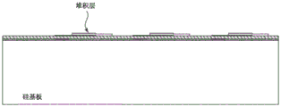
Fig. 9 is a schematic cross-sectional view illustrating a build-up layer on the layers of fig. 8 during a method of forming an example bulk acoustic wave structure, according to aspects of the present disclosure.
Fig. 10 is a schematic cross-sectional view illustrating a protective layer on the layer of fig. 9 during a method of forming an example bulk acoustic wave structure, in accordance with aspects of the present disclosure.
Fig. 11 is a schematic cross-sectional view illustrating an acoustic energy management structure extending over a portion of the layer of fig. 10 during a method of forming an example bulk acoustic wave structure, in accordance with aspects of the present disclosure.
Fig. 12 is a schematic cross-sectional view illustrating interconnections for electrical connection to a plate disposed relative to the layers of fig. 10 during a method of forming an example bulk acoustic wave structure, according to aspects of the present disclosure.
Fig. 13 is a schematic cross-sectional view illustrating removal of a portion of a substrate to reduce the thickness of the substrate relative to the layers of fig. 12 during a method of forming an example bulk acoustic wave structure, according to aspects of the present disclosure.
Fig. 14A, 14B, and 14C are schematic cross-sectional and perspective views illustrating dry etching of additional portions of a substrate to form fluid paths relative to the layers of fig. 13 during a method of forming an example bulk acoustic wave structure, according to aspects of the present disclosure.
Fig. 15A, 15B, 15C, 15D, and 15E are schematic cross-sectional, and perspective views illustrating a BAW die flip-chip mounted to a board relative to the bulk acoustic wave structure of fig. 14 during a method of forming an example bulk acoustic wave structure, according to aspects of the present disclosure.
Fig. 16 is a schematic cross-sectional view illustrating attachment of a fluid wall structure relative to the bulk acoustic wave structure of fig. 14 during a method of forming an example fluidic device, according to aspects of the present disclosure.
Fig. 17A, 17B, and 17C are schematic cross-sectional views illustrating underfill wicking under a flip-chip mounted die with respect to the device of fig. 16 during a method of forming an example bulk acoustic wave structure, according to aspects of the present disclosure.
Fig. 18 is a schematic cross-sectional view illustrating silanization, functionalized printing, and spotting with respect to the device of fig. 17 during a method of forming an exemplary bulk acoustic wave structure, according to aspects of the present disclosure.
Fig. 19A, 19B, and 19C are schematic cross-sectional views illustrating a fluid cavity cover attached to a fluid wall structure relative to the apparatus of fig. 18 during a method of forming an example bulk acoustic wave structure, according to aspects of the present disclosure.
Fig. 20 is a schematic diagram illustrating an additional method of attaching a fluid cavity cover to a fluid wall structure relative to the device of fig. 18 during a method of forming an example bulk acoustic wave structure, according to aspects of the present disclosure.
Fig. 21 is a schematic cross-sectional view illustrating a silicon substrate with silicon oxide and silicon nitride films deposited during a method of forming an example bulk acoustic wave structure, according to aspects of the present disclosure.
Fig. 22 is a schematic cross-sectional view illustrating electrode formation, silicon oxide deposition, and planarization of a surface using a Chemical Mechanical Polishing (CMP) process relative to fig. 21 during a method of forming an example bulk acoustic wave structure, according to aspects of the present disclosure.
Fig. 23 is a schematic cross-sectional view illustrating a tilted shear axis piezoelectric film deposited relative to fig. 22 during a method of forming an example bulk acoustic wave structure, according to aspects of the present disclosure.
Fig. 24 is a schematic cross-sectional view illustrating deposition and patterning of a second electrode over a piezoelectric layer relative to fig. 23 during a method of forming an example bulk acoustic wave structure, according to aspects of the present disclosure.
Fig. 25 is a schematic cross-sectional view illustrating deposition and patterning of a build-up layer relative to fig. 24 during a method of forming an example bulk acoustic wave structure, according to aspects of the present disclosure.
Fig. 26 is a schematic cross-sectional view illustrating deposition and patterning of a protective layer relative to fig. 25 during a method of forming an example bulk acoustic wave structure, according to aspects of the present disclosure.
Fig. 27 is a schematic cross-sectional view illustrating fabrication of an acoustic reflector over a resonator relative to fig. 26 during a method of forming an example bulk acoustic wave structure, according to aspects of the present disclosure.
Fig. 28 is a schematic cross-sectional view illustrating fabricating bumps for electrical connection to a board relative to fig. 27 during a method of forming an example bulk acoustic wave structure, according to aspects of the present disclosure.
Fig. 29 is a schematic cross-sectional view illustrating backgrinding a portion of a substrate relative to fig. 28 to reduce the thickness of the substrate during a method of forming an example bulk acoustic wave structure, in accordance with aspects of the present disclosure.
Fig. 30 is a schematic cross-sectional view illustrating dry etching of a portion of a substrate relative to fig. 29 to form a fluid path in a region of a resonator during a method of forming an example bulk acoustic wave structure, according to aspects of the present disclosure.
Fig. 31 is a schematic cross-sectional view illustrating a BAW biosensor die flip-chip mounted to a printed circuit board relative to fig. 30 during a method of forming an example bulk acoustic wave structure, according to aspects of the present disclosure.
Fig. 32A and 32B are schematic cross-sectional and perspective views illustrating attachment of a separate fluid wall structure relative to fig. 31 during a method of forming an example bulk acoustic wave structure, in accordance with aspects of the present disclosure.
Fig. 33 is a schematic cross-sectional view illustrating the device after wicking underfill under a flip-chip mounted die relative to fig. 32A and 32B during a method of forming an example bulk acoustic wave structure, according to aspects of the present disclosure.
Fig. 34 is a schematic cross-sectional view illustrating silanization, functionalized printing and spotting accomplished relative to fig. 33 during a method of forming an exemplary bulk acoustic wave structure, according to aspects of the present disclosure.
Fig. 35 is a schematic cross-sectional view illustrating a fluid cavity cover attached to a fluid wall structure relative to fig. 34 during a method of forming an example bulk acoustic wave structure, according to aspects of the present disclosure.
Fig. 36 is a schematic plan view of an exposed resonator side and an independent wall of a BAW sensor die during a method of forming an example bulk acoustic wave structure, according to aspects of the present disclosure.
Fig. 37 is a schematic cross-sectional view illustrating an alternative method of attaching a cap to the BAW die of fig. 31 during a method of forming an example bulk acoustic wave structure, in accordance with aspects of the present disclosure.
Fig. 38 is a schematic cross-sectional view illustrating a silicon-on-insulator (SOI) wafer that may be utilized in methods of forming example bulk acoustic wave structures according to aspects of the present disclosure.
Fig. 39 is a schematic cross-sectional view illustrating a patterned hard mask and wet etch with respect to the top silicon of fig. 38 during a method of forming an example bulk acoustic wave structure, in accordance with aspects of the present disclosure.
Fig. 40 is a schematic cross-sectional view illustrating deposition of a silicon nitride film relative to fig. 39 during a method of forming an example bulk acoustic wave structure, in accordance with aspects of the present disclosure.
Fig. 41 is a schematic cross-sectional view illustrating electrode formation, silicon oxide deposition, and planarization of a surface using a CMP process relative to fig. 40 during a method of forming an example bulk acoustic wave structure, according to aspects of the present disclosure.
Fig. 42 is a schematic cross-sectional view illustrating a tilted shear axis piezoelectric film deposited relative to fig. 41 during a method of forming an example bulk acoustic wave structure, according to aspects of the present disclosure.
Fig. 43 is a schematic cross-sectional view illustrating an electrode deposited and patterned over a piezoelectric layer relative to fig. 42 during a method of forming an example bulk acoustic wave structure, according to aspects of the present disclosure.
Fig. 44 is a schematic cross-sectional view illustrating deposition and patterning of a build-up layer relative to fig. 43 during a method of forming an example bulk acoustic wave structure, according to aspects of the present disclosure.
Fig. 45 is a schematic cross-sectional view illustrating an example of fabricating an air cavity, acoustic energy management structure on a resonator relative to fig. 44 during a method of forming an example bulk acoustic wave structure, in accordance with aspects of the present disclosure.
Fig. 46 is a schematic cross-sectional view illustrating fabricating bumps for electrical connection to a board relative to fig. 45 during a method of forming an example bulk acoustic wave structure, according to aspects of the present disclosure.
Fig. 47 is a schematic cross-sectional view illustrating backgrinding of a substrate relative to fig. 46 to reduce the thickness of the substrate during a method of forming an example bulk acoustic wave structure, according to aspects of the present disclosure.
Fig. 48 is a schematic cross-sectional view illustrating a BAW biosensor die flip-chip mounted to a board relative to fig. 47 during a method of forming an example bulk acoustic wave structure, according to aspects of the present disclosure.
Fig. 49A and 49B are a schematic cross-sectional view and a schematic plan view illustrating the attachment of a separate fluid wall structure relative to fig. 48.
Fig. 50 is a schematic cross-sectional view illustrating underfill wicking relative to the flip-chip mounted die of fig. 49 during a method of forming an example bulk acoustic wave structure, according to aspects of the present disclosure.
Fig. 51 is a schematic cross-sectional view illustrating silanization, functionalized printing and spotting relative to fig. 50 during a method of forming an exemplary bulk acoustic wave structure according to aspects of the present disclosure.
Fig. 52A and 52B are schematic and plan cross-sectional views illustrating a fluid cavity cover attached to a fluid wall structure relative to fig. 51 during a method of forming an example bulk acoustic wave structure, in accordance with aspects of the present disclosure.
Fig. 53 is a schematic cross-sectional view illustrating an example of fabricating an acoustic mirror, acoustic energy management structure on a resonator relative to fig. 44 during a method of forming an example bulk acoustic wave structure, in accordance with aspects of the present disclosure.
Fig. 54 is a schematic cross-sectional view illustrating fabricating bumps for electrical connection to a board relative to fig. 53 during a method of forming an example bulk acoustic wave structure, according to aspects of the present disclosure.
Fig. 55 is a schematic cross-sectional view illustrating backgrinding of a substrate relative to fig. 54 to reduce the thickness of the substrate during a method of forming an example bulk acoustic wave structure, according to aspects of the present disclosure.
Fig. 56 is a schematic cross-sectional view illustrating a BAW biosensor die flip-chip mounted to a board relative to fig. 55 during a method of forming an example bulk acoustic wave structure, according to aspects of the present disclosure.
Fig. 57 is a schematic cross-sectional view illustrating attachment of a separate fluid wall structure relative to fig. 56 during a method of forming an example bulk acoustic wave structure, in accordance with aspects of the present disclosure.
Fig. 58 is a schematic cross-sectional view illustrating underfill wicking relative to the flip-chip mounted die of fig. 57 during a method of forming an example bulk acoustic wave structure, according to aspects of the present disclosure.
Fig. 59 is a schematic cross-sectional view illustrating silanization, functionalized printing and spotting relative to fig. 58 during a method of forming an example bulk acoustic wave structure according to aspects of the present disclosure.
Fig. 60 is a schematic cross-sectional view illustrating a fluid cavity cover attached to a fluid wall structure relative to fig. 59 during a method of forming an example bulk acoustic wave structure, in accordance with aspects of the present disclosure.
Fig. 61 is a schematic plan view of an interconnect side and an independent wall of a BAW sensor die upon completion of a method of forming an example bulk acoustic wave structure according to aspects of the present disclosure.
Fig. 62 is a schematic plan view of an exposed resonator side and an independent wall of a BAW sensor die upon completion of a method of forming an example bulk acoustic wave structure according to aspects of the present disclosure.
The drawings are not necessarily to scale. Like reference numerals are used in the figures to denote like parts. However, it will be understood that the use of reference numerals to refer to parts in one figure is not intended to limit parts in another figure labeled with the same reference numeral.
Detailed Description
In the following detailed description, several specific embodiments of compounds, compositions, devices, systems, and methods are disclosed. It is to be understood that other embodiments are contemplated and may be made without departing from the scope or spirit of the present disclosure. The following detailed description is, therefore, not to be taken in a limiting sense.
It will be understood that, although the terms first, second, etc. may be used herein to describe various elements, these elements should not be limited by these terms. These terms are only used to distinguish one element from another. For example, a first element could be termed a second element, and, similarly, a second element could be termed a first element, without departing from the scope of the present disclosure. As used herein, the term "and/or" includes any and all combinations of one or more of the associated listed items.
Relative terms, such as "below" or "above" or "upper" or "lower" or "top" or "bottom" or "horizontal" or "vertical" may be used herein to describe one element, layer or region's relationship to another element, layer or region as illustrated. It will be understood that these terms and those discussed above are intended to encompass different orientations of the device in addition to the orientation of the figures.
The terminology used herein is for the purpose of describing particular embodiments only and is not intended to be limiting of the disclosure. As used herein, the singular forms "a", "an" and "the" are intended to include the plural forms as well, unless the context clearly indicates otherwise. It will be further understood that the terms "comprises" and/or "comprising," when used herein, specify the presence of stated features, integers, steps, operations, elements, and/or components, but do not preclude the presence or addition of one or more other features, integers, steps, operations, elements, components, and/or groups thereof. As used herein, the terms "adjacent" and "adjacent" as applied to a particular layer or element refer to being proximate or near another layer or element and include the possible presence of one or more intervening layers or elements, either directly on or directly in contact with the other layer or element, unless specified to the contrary herein.
In the case of piezoelectric crystal resonators, the acoustic wave can be embodied as a Bulk Acoustic Wave (BAW) propagating through the interior of the substrate, or a Surface Acoustic Wave (SAW) propagating on the surface of the substrate, SAW devices involving the conduction of an acoustic wave (typically comprising a two-dimensional rayleigh wave) along the surface of the piezoelectric material using an interdigital transducer, the wave being limited to a penetration depth of about one wavelength. In BAW devices, three wave modes can propagate, namely one longitudinal mode (embodying shear waves, also known as compression/tension waves) and two shear modes (embodying shear waves, also known as shear waves), where the longitudinal and shear modes identify vibrations of the particle motion parallel or perpendicular to the wave propagation direction, respectively. Longitudinal modes are characterized by compression and elongation in the direction of wave propagation, while shear modes consist of motion perpendicular to the direction of propagation. The longitudinal and shear modes consist of motion perpendicular to the longitudinal direction of action.
The present disclosure relates to methods of forming acoustic resonator devices and devices formed thereby including Bulk Acoustic Wave (BAW) resonators disposed on a substrate. The BAW resonator comprises a first conductive material forming a first electrode, a piezoelectric material and a second conductive material forming a second electrode, the piezoelectric material being located between the two electrodes. An acoustic energy management structure for reducing or avoiding the dissipation of acoustic waves into the substrate is formed on at least a portion of the active region of one surface of the BAW resonator, and an interfacial layer is formed on the opposing surface of at least a portion of the active region of the BAW resonator to allow subsequent functionalization of the active region.
According to aspects of the present disclosure, acoustic wave structure devices can be fabricated using micro-electromechanical systems (MEMS) techniques for producing microscale features suitable for biosensors, functionalized materials (e.g., specific binding materials). Deposition techniques such as Atomic Layer Deposition (ALD), Chemical Vapor Deposition (CVD), or Physical Vapor Deposition (PVD) may be used in conjunction with one or more masks (e.g., photolithographic masks) to pattern various portions of the devices being formed.
The previous method of manufacturing BAW devices comprises the steps of:
1. a resonator was fabricated with a reflective pedestal, bottom electrode, tilted shear axis aluminum nitride, and top electrode.
2. The flip-chip interconnect bumps (e.g., copper pillars) are fabricated from tin.
3. Depositing a water vapor barrier layer protecting the electrode. An example of a suitable material is CVD Si3N4Or ALD Al2O3。
4. An adhesion layer for a self-assembled monolayer (SAM) is deposited on the vapor barrier layer. Examples of suitable materials include SiO2、TiO2Or HfO2. TheseThe material may be deposited by Atomic Layer Deposition (ALD) or Chemical Vapor Deposition (CVD).
5. The die is mounted on the laminate board over the socket in the board. Slots in the plate define fluid channels. Additional components (e.g., switches, capacitors, and resistors) are mounted on the board to make the rf sensor module.
6. A self-assembled monolayer (SAM) is deposited. An example of a suitable material is propyltrimethoxysilane. The SAM coating is applied to improve SiO2Adhesion or adhesion between the layer and the organic polymer.
7. Functionalization (also known as bioreceptors) was printed with microarray spotting pins.
Chemical blocks of SAM unmarked areas. This may prevent unwanted attachment of analyte to the SAM when testing the sample. Unbound excess chemical blocking chemical washes off the device.
9. A fluid package is manufactured. One example of a fluid package is a multilayer stamped or laser cut laminate with adhesive. The layer is pre-cut and processed and then applied and secured with a pressure sensitive adhesive.
10. Analyte flows through the sensor cavity, analyte binds to the functionalization, and the resonator is driven by the shear radio frequency to detect the frequency shift of the bound analyte.
Methods such as these produce devices that include long electrical leads to separate the electrical bumps from the fluid channels. Furthermore, it is difficult to create a high density resonator array with fluidic and electrical connections on the same side of the die. Flip chip mounting of a BAW sensor formed as above onto a printed circuit board is one method of connecting the sensor to the board. A BAW containing a die is mounted on the board over the slot that ultimately forms the fluid channel. The thickness of the Printed Circuit Board (PCB) determines the height of the fluid channel. Reducing the height of the fluid channel requires reducing the thickness of the PCB.
These problems are magnified when considering sensor arrays. As rows of resonators are placed in the fluid path, the electrical lead lengths will increase. For example, if there are four resonators in the width of the fluid path, the length of the lead to the resonator in the center of the fluid path will be long. This in turn makes it difficult to solve high density resonator sensor arrays. As an example, the sensor array may range from 2 × 2 (4 in total) to 50 × 50 (2500 in total). Even 3 x 3 (9 total) arrays, which may be a favorable tradeoff of cost and performance, are difficult to fabricate with the previously used methods. The thickness of the currently commonly used PCB is about 200 microns, thus determining the thickness of the fluid channel.
According to aspects of the present disclosure, examples employ flip-chip connections with interconnect pillars to electrically and/or mechanically connect with a circuit board. An acoustic energy management structure (e.g., an air cavity or acoustic mirror) may be employed on the first side of the resonator. An opposite second side of the resonator may be exposed to serve as an active portion of the sensor. The disclosed method further includes the step of removing a portion of the substrate material. The timing of the step of removing a portion of the substrate is important because if the substrate is removed prematurely in the process, the substrate will be fragile and therefore difficult to handle by certain operations.
Devices at various stages of manufacture according to some methods are disclosed, for example, in fig. 1A through 1G. Fig. 1A illustrates a substrate 102 having a first surface 103 and an opposing second surface 104. For example, the substrate 102 may include silicon. The substrate may have various structures or layers formed on either surface thereof and still be useful in the disclosed methods.
Fig. 1B illustrates the substrate 102 after the first conductive material 106 has been disposed on at least a portion of the first surface 103 of the substrate 102. The first conductive material 106 or a first electrode formed therefrom can be described as having a first surface 105 adjacent or proximate to the substrate 102 and an opposing second surface 107 opposite the first surface 103. The step of disposing the first conductive material may include a deposition step, a patterning step, or any combination thereof. In some embodiments, the conductive material may be deposited on at least some portions of the first surface of the substrate, or on any structure or device formed on the first surface of the substrate, and then the conductive material may be patterned after one or more deposition steps. Deposition techniques such as Atomic Layer Deposition (ALD), Chemical Vapor Deposition (CVD), or Physical Vapor Deposition (PVD) may be used in conjunction with one or more masks (e.g., photolithographic masks) to pattern certain portions of the first conductive material, and if desired, any of the other layers, materials, or structures discussed herein. In some embodiments, the first conductive material may include more than one material, more than one layer, or a combination thereof. In some embodiments, the first conductive material may include aluminum (a1), copper (Cu), gold (Au), platinum (Pt), combinations thereof, alloys thereof, or combinations thereof. In some embodiments, the first conductive material comprises Al, an alloy thereof, or a multilayer structure comprising at least one Al layer. In some embodiments, for example, the first conductive material may include Al or a bilayer structure including at least an A1Cu layer and a tungsten (W) layer.
Fig. 1C illustrates the device after disposing a piezoelectric material 110 over at least some portion of the first electrode. In some embodiments, the piezoelectric material may be deposited on all portions of the first electrode. In some embodiments, the piezoelectric material may be deposited on all portions of the first electrode that are not disposed on the first surface of the substrate or on any devices or structures formed thereon. In some embodiments, a tilted c-axis hexagonal crystal structure piezoelectric material (e.g., A1N or ZnO) may be used as the piezoelectric material.
In certain embodiments, the piezoelectric material can include an aluminum nitride or zinc oxide material having a c-axis with an orientation distribution that is not primarily parallel (and may also not be perpendicular) to a normal to a face of the substrate. Such a c-axis orientation distribution can produce a shear displacement, which advantageously enables the MEMS resonator device to operate as a liquid, for example, in a sensor and/or microfluidic device. In certain embodiments, the piezoelectric material comprises a c-axis having a longitudinal orientation.
A method of forming a hexagonal crystal structure piezoelectric material including a c-axis having an orientation distribution that is predominantly non-parallel to the normal to the face of the substrate is disclosed in U.S. patent application serial No. 15/293,063 filed on 10/13/2016, which is incorporated herein by reference. Additional methods of forming piezoelectric materials with a tilted c-axis orientation are disclosed in U.S. patent No. 4,640,756, published 2/3 1987, which is incorporated herein by reference.
Fig. 1D illustrates the device after disposing a second conductive material on at least a portion of the piezoelectric material. The step of disposing the second conductive material may include a deposition step, a patterning step, or any combination thereof. As shown in fig. 1D, in some embodiments, a conductive material may be deposited on at least some portions of the piezoelectric material, and then the conductive material may be patterned after one or more deposition steps to form the second electrode 112. The second conductive material extends substantially parallel to the first surface of the substrate. At least a portion of the second electrode 112 overlaps the first electrode 106. The stacking of the first electrode 106, the piezoelectric material 110, and the second electrode 112 in three overlapping regions forms a bulk acoustic wave resonator 114. The bulk acoustic wave resonator 114 has a first side 112 parallel to the first surface 103 of the substrate 102 and furthest from the first surface 103.
Fig. 1E illustrates the device after forming an acoustic management structure 116 on some portion of the first side of the bulk acoustic wave resonator 114. The acoustic energy management structure may, for example, comprise an air cavity or a reflector stack. The purpose of the acoustic management structure is to contain the acoustic energy in the device. The reflector stack acts as an acoustic mirror and may have better mechanical strength advantages. The air chambers may retain energy better, but may also work in devices with overall weaker mechanical strength, or other structures may be added to address the lack of mechanical strength.
In certain embodiments, the energy management structure is an air gap or cavity. The cavity may be formed by forming two side walls and a "top" layer, thereby forming a cavity below and between the top and the walls, respectively. The walls and roof may be formed using a photolithographic material (e.g., a photoimageable material such as a photoimageable epoxy material). Specific examples of such materials may include TMMF (Tokyo Ohka Kogya Co.) or SU-8(MicroChem Inc, Newton MA). For example, the wall and top features may have a thickness of 3 to 80 microns, or have a thickness of 10 to 30 microns. The width dimension of the walls (e.g., the distance from one wall to the other) may be, for example, 3 to 30 microns, or may be 5 to 15 microns. For example, the area of the top may be 100 square microns to 500,000 square microns, or may be 2500 square microns to 200,000 square microns.
In certain embodiments, the acoustic energy management structure is an acoustic reflector. The acoustic reflector serves to reflect the acoustic waves and thus reduce or avoid their dissipation in the substrate. In certain embodiments, the acoustic reflector may comprise different materials (e.g., silicon oxycarbide [ SiOC)]Silicon nitride [ Si ]3N4]Silicon dioxide [ SiO ]2]Aluminum nitride [ AlN ]]Tungsten [ W ]]And molybdenum [ Mo ]]) Optionally embodied in a quarter wave bragg mirror. In some embodiments, other types of acoustic reflectors may also be used.
Further details regarding possible embodiments of the acoustic energy management structure are discussed below with respect to specific embodiments of the disclosed method.
Fig. 1F illustrates the apparatus after depositing a third conductive material 118 on a portion of the second conductive material 112. It should be noted that the first, second and third conductive materials may be the same or different. A third conductive material is deposited on the portion of the second conductive material that extends beyond the bulk acoustic wave resonator 112. In other words, the third conductive material does not cover any part of the bulk acoustic wave resonator, but covers a part of the second conductive material. The third conductive material forms an interconnect extending over the acoustic energy management structure (in a direction perpendicular to the first surface 103 of the substrate 102). The third conductive material may be described or formed as a pillar structure 118 that may be electrically connected to another device or structure in contact therewith.
Fig. 1G illustrates the device after the next step, which includes removing a portion of the substrate 102 to expose the first surface 105 of the first electrode 106. The step of removing a portion of the substrate may include one or more processes. In some embodiments, removing a portion of the substrate may include mechanical and chemical processing steps. In some embodiments, the first step of removing a portion of the substrate may remove a substantially constant thickness across the substrate. In some embodiments, this first step may be performed by removing additional substrate material only at certain portions of the substrate. In some embodiments, for example, the mechanical removal step may be followed by a chemical removal step. In some such embodiments, the first step may provide a substrate having a thickness of 100 to 600 microns, 100 to 550 microns, 200 to 400 microns, or 250 to 350 microns, or about 300 microns. An exemplary starting thickness of the substrate may be about 725 microns.
The step of exposing the first surface 105 of the first electrode 106 exposes a second side of the bulk acoustic wave sensor 114 for use or further processing. It is noted that at this point, the second surface of the bulk acoustic wave resonator 114 may expose the electrode material 106 or some other layer already disposed on the substrate prior to depositing the first electrode material.
Additional layers that may be exposed (or even applied) at this time may include an interface layer. The interface layer may serve to allow or more easily allow the active surface of the bulk acoustic wave resonator 114 to be functionalized. In certain embodiments, an interface layer may be patterned or otherwise available to receive a self-assembled monolayer (SAM) over the entire active area of the bulk acoustic wave resonator to allow the SAM and a functionalizing (e.g., specific binding) material to be applied to the interface layer to overlap the entire active area. In other embodiments, the blocking layer may be patterned on the interface layer, or only a portion of the interface layer may be used to receive the SAM over only a portion of the active region, to allow the SAM and the functionalizing material to be applied to the interface layer to overlap only a portion of the active region.
In certain embodiments, photolithography may be used to facilitate the patterning of the interface material or blocking material on portions of the MEMS resonator device. Photolithography involves the use of light to transfer a geometric pattern from a photomask to a photosensitive chemical photoresist on a substrate and is a process well known to those of ordinary skill in the art of semiconductor manufacturing. Typical steps employed in photolithography include wafer cleaning, photoresist application (involving either positive or negative photoresist), mask alignment, and exposure and development. After defining features in the photoresist on the desired surface, the interface layer may be patterned by etching in one or more gaps in the photoresist layer, and the photoresist layer may then be removed (e.g., by applying an oxygen-containing plasma for ashing or other removal process using a liquid photoresist stripper).
In certain embodiments, the interfacial layer may comprise a hydroxylated oxide surface suitable for forming an organosilane SAM layer. A preferred interfacial layer material comprising a hydroxylated oxide surface is silicon dioxide SiO2]. Alternative materials for forming the interfacial layer comprising hydroxylated oxide surfaces include titanium dioxide [ TiO [ ]2]And tantalum pentoxide [ Ta ]2O5]. Other alternative materials including hydroxylated oxide surfaces are known to those skilled in the art and such alternatives are considered to be within the scope of the present disclosure.
In other embodiments, the interfacial layer comprises gold or another noble metal (e.g., ruthenium, rhodium, palladium, osmium, iridium, platinum, or silver) suitable for receiving the thiol-based SAM.
In certain embodiments that include electrode materials that are subject to corrosion, a hermetic layer may be applied between the top-side electrode and the interface layer. When noble metals (e.g., gold, platinum, etc.) are used for the topside electrode, the hermetic layer may not be needed. If provided, the air barrier preferably includes a material having a low water vapor transmission rate (e.g., no greater than 0.1 (g/m)2Day) of the dielectric material. After depositing these layers, a SAM may be formed over the interfacial layer, the SAM preferably comprising an organosilane material. The gas-tight layer protects the reactive electrode material (e.g., aluminum or aluminum alloy) from the corrosive liquid environment, and the locally patterned interfacial layer promotes proper chemical bonding of the SAM.
In certain embodiments, the hermetic layer and/or interfacial layer may be applied by one or more deposition processes such as Atomic Layer Deposition (ALD), Chemical Vapor Deposition (CVD), or Physical Vapor Deposition (PVD). Among the aforementioned processes, ALD is preferred for depositing at least the gas-tight layer (and may also be preferred for depositing the interfacial layer) because it is capable of providing an excellent conformal coating with good step coverage over device features, thereby providing a pinhole-free layer structure. In addition, ALD is capable of forming a thin, uniform layer that provides relatively little attenuation of acoustic vibrations that would otherwise result in device performance degradation. The adequacy of coverage is important for the hermetic layer (if present) to avoid corrosion of the underlying electrodes. If ALD is used to deposit the hermetic layer, in certain embodiments, the hermetic layer may include a thickness in a range from about 10nm to about 25 nm. In certain embodiments, the air barrier layer has a thickness of about 15nm, or about 12nm to about 18 nm. Conversely, if another process such as CVD is used, the hermetic layer may include a thickness in a range of about 80nm to about 150nm or more, or in a range of about 80nm to about 120 nm. In view of the above two processes, the thickness of the inner liner may be in the range of about 5nm to about 150 nm. If ALD is used to deposit the interfacial layer, the interfacial layer may include a thickness in the range of about 5nm to about 15 nm. In certain embodiments, the interfacial layer may comprise a thickness in the range of about 10nm, or about 8nm to about 12 nm. Other interfacial layer thickness ranges and/or deposition techniques besides ALD may be used in certain embodiments. In certain embodiments, the hermetic layer and the interfacial layer may be sequentially applied in a vacuum environment, thereby promoting a high quality interface between the two layers.
If provided, the hermetic layer can include a material that functions as a dielectric material and has a low water vapor transmission rate (e.g., no greater than 0.1 g/m)2A/day) oxide, nitride or oxynitride material. In certain embodiments, the hermetic layer comprises aluminum oxide (Al)2O3) Or silicon nitride (SiN). In certain embodiments, the interfacial layer comprises SiO2、TiO2Or Ta2O5At least one of (1). In certain embodiments, multiple materials may be combined in a single hermetic layer, and/or the hermetic layer may include multiple sub-layers of different materials. Preferably, the gas barrier is further selected to promote compatibility with the underlying reactive metal (e.g., aluminum or aluminum alloy) electrode structure of the acoustic resonator structure. Although aluminum or aluminum alloys are often used as electrode materials in bulk acoustic wave resonators, various transition and post-transition metals can be used for such electrodes.
After deposition of the interface layer (optionally disposed on the underlying gas barrier layer), the SAM is preferably formed on the interface layer. SAMs are typically formed by exposing a solid surface to amphiphilic molecules having chemical groups that exhibit strong affinity for the solid surface. When an interfacial layer comprising a hydroxylated oxide surface is used, organosilane SAMs are particularly preferred for attachment to the hydroxylated oxide surface. The organosilane SAM promotes surface bonding through silicon-oxygen (Si-O) bonds. More specifically, organosilane molecules include hydrolysis-sensitive groups and organic groups and are therefore useful for coupling inorganic materials to organic polymers. Organosilane SAMs can be formed by exposing a hydroxylated oxide surface to an organosilane material in the presence of trace amounts of water to form intermediate silanol groups. These groups then react with free hydroxyl groups on the hydroxylated surface to covalently immobilize the organosilane. Examples of possible organosilane based SAMs that are compatible with the interfacial layer comprising a hydroxylated oxide surface include 3-Glycidoxypropyltrimethoxysilane (GPTMS), 3-mercaptopropyltrimethoxysilane (MPTMS), 3-Aminopropyltrimethoxysilane (APTMS), and Octadecyltrimethoxysilane (OTMS), including ethoxy-and chloro-variants thereof. Other silanes useful for the SAM include poly (ethylene glycol) (PEG) conjugated variants. Those skilled in the art will recognize that other alternatives exist and are considered to be within the scope of the present disclosure. Exemplary SAMs may include a thickness of at least 0.5nm or greater. Preferably, the SAM bonds readily to the locally patterned interfacial layer, but does not bond readily to other adjacent material layers (e.g., the hermetic layer, the piezoelectric material, and/or the blocking material layer).
When using an interfacial layer comprising gold or another noble metal, a thiol-based (e.g. alkanethiol-based) SAM layer may be used. Alkanethiols are molecules with alkyl chains as backbone, tail groups and S-H head groups. Thiols can be used for the noble metal interfacial layer due to the strong affinity of sulfur for these metals. Examples of thiol-based SAMs that may be used include, but are not limited to, 1-dodecanethiol (DDT), 11-mercaptoundecanoic acid (MUA), and hydroxyl-terminated (hexaethyleneglycol) undecanethiol (1-UDT). These thiols contain the same backbone but different end groups-i.e., methyl (CH) for DDT, MUA and 1-UDT, respectively3) Carboxyl (COOH) and hydroxyl-terminated hexaethylene glycol (HO- (CH)2CH2O)6). In certain embodiments, the solvent may be selected by use of a suitable solvent (e.g., absolute ethanol)) The gold surface was incubated in a thiol solution to form the SAM.
After formation of the SAM, the SAM can be biologically functionalized, such as by accepting at least one functionalized (e.g., specifically binding) material. In certain embodiments, specific binding materials can be applied on or over the SAM using microarray spotting pins or other suitable methods. Since the SAM and the underlying interface layer are patterned with high dimensional tolerances (e.g. using photolithography to define the interface layer) only on a part of the resonator structure (including the substrate) and the subsequently applied specific binding material is preferably only attached to the SAM, a higher dimensional tolerance can be achieved for the positioning of the specific binding material compared to the spotting of the microarray alone.
FIG. 1H illustrates the apparatus after additional processing. For example, the device of fig. 1H has been flipped over and then placed on the second substrate 120, for example, to make electrical connections with other devices. The device is electrically connected to a second substrate 120, which may be a Printed Circuit Board (PCB), for example. For example, the second substrate 120 may be connected to the device through electrical contact pads 122. The device of fig. 1H also includes a fluid wall 122 formed on the second substrate 120. The fluid walls may be formed from any suitable material, such as a thin polymeric material and/or a laser-cut "stencil" layer of laminate material, optionally including one or more self-adhesive surfaces (e.g., tape). Alternatively, such walls may be formed with SU-8 negative epoxy or other photoresist material prior to deposition of the SAM layer, functionalization layer, and/or blocking layer. The device of FIG. 1H also includes a cap layer 124 or cap layer. The cap 124 may be formed by defining a port (e.g., by laser cutting or water jet cutting) in a layer of suitable material (e.g., preferably a substantially inert polymer, glass, silicon, ceramic, etc.) and adhering the cap or cap layer to the top surface of the fluid wall 122. The combination of the cap 124 and the fluid wall 122 forms a fluid channel 126.
FIG. 1I illustrates the device after functionalization, denoted YYYY, and blocking denoted XXXXX. Examples of specific binding materials for functionalization include, but are not limited to, antibodies, receptors, ligands, and the like. The specific binding material is preferably configured to receive a predetermined target substance (e.g., a molecule, protein, DNA, virus, bacteria, etc.). The functionalized layer comprising the specific binding material may comprise a thickness in a range of about 5nm to about 1000nm, or about 5nm to about 500 nm. In certain embodiments, an array of different specific binding materials may be provided on different active areas of a multi-resonator device (i.e., a resonator device comprising multiple active areas), optionally in combination with one or more active areas without specific binding materials to serve as a comparison (or "reference") area. In certain embodiments, the functionalizing material may provide the utility of non-specific binding.
Fig. 1J provides an alternative to the step of forming the fluid wall to which the cap 124 is attached. In this embodiment, the cover 124 is directly attached to the electrode material forming the channel 128.
Figures 2 through 20 illustrate a more specific method of forming a fluidic device including a bulk acoustic wave resonator according to one example of the present disclosure. In general, materials may be deposited using deposition techniques such as Atomic Layer Deposition (ALD), Chemical Vapor Deposition (CVD), or Physical Vapor Deposition (PVD), or other techniques. One or more masks (e.g., photolithographic masks), stop layers, etch layers, and the like may also be used to pattern certain portions of any material deposited herein to form the layers or structures shown. Although fig. 2-20 illustrate methods of forming three resonator structures, associated electrical connections and structures, for clarity, reference numerals are typically provided for only one of the repeating structures.
Fig. 2 generally illustrates a substrate 200 having a first surface 201 and a second surface 202. A sacrificial layer 203 has been formed on a portion of the first surface 201. The sacrificial layer may protect the resonator device formed by the method when the second side 202 of the substrate 200 is partially removed. The substrate may be, for example, a silicon substrate and the sacrificial material may be, for example, aluminum. The sacrificial layer is typically deposited and patterned in the area where the resonator is to be formed.
Fig. 3 illustrates the structure after a step intended to form a planar surface to have additional process steps performed thereon. In particular, additional silicon oxide material may be deposited onto the sacrificial material 202 and exposed portions of the first surface 201 of the substrate 200. The deposition of the silicon oxide material may be followed by a Chemical Mechanical Polishing (CMP) process, for example to form a planar silicon oxide layer 204, the top surface of which is flush with the sacrificial layer 203. In other words, the top surface of the silicon oxide layer 204 is flush with the top surface of the patterned sacrificial layer 202 deposited in the step shown in fig. 2. The silicon oxide layer 204, the sacrificial layer, or both may serve not only as a planarization layer on which additional structures are formed, but may also serve as a silicon etch stop layer, a functionalized bonding surface, or both in steps of a subsequently disclosed process. Alternatively, if the silicon oxide material has a greater thickness, it may also provide some temperature compensation characteristics. For example, a silicon oxide material having a thickness of at least 300 nanometers may facilitate temperature compensation of the device. For example, the particular thickness of the silicon oxide material may depend at least in part on the operating frequency of the device, the material in the device, the thickness of the various materials in the device, or a combination thereof.
Fig. 4 illustrates the structure after forming a passivation layer 206 on the sacrificial layer 202 and the silicon oxide layer 204. The passivation layer 206 may, for example, function as a moisture barrier. For example, illustrative passivation layers may include silicon nitride and aluminum oxide (e.g., ALD deposited AlO). The passivation layer may provide moisture resistance that may be used to protect the device.
Fig. 5 illustrates the structure after the sacrificial layer 202 has been removed. For example, the sacrificial layer 202 may be removed by etching the sacrificial layer 202 from the non-substrate side of the structure to form the resonator gap 208. In some particular embodiments, a photoresist pattern may be applied and holes (not shown) may be etched through the passivation layer 206 overlying the sacrificial layer 202. Illustrative etchants useful for this particular set of materials may include "16-1-1-2," which refers to a material that contains 16 parts by volume of H3PO41 part of HNO31 part of CH3COOH: 2 parts H2O, which does not etch silicon nitride or silicon, but does etch aluminum oxide. If other materials are used for the passivation layer 206 and the sacrificial layer 202, one skilled in the art will know possible etchant compositions. The formation of the resonator gap 208 allows the finally formed resonator to be probed and trimmed for end use.
Fig. 6 illustrates the structure after the first electrode 210 is formed thereon. The formation or deposition of the first electrode 210 may include deposition of a material, patterning of a material, or any combination thereof. Silicon oxide material 212 is then deposited on the structure and planarized (e.g., using CMP) to form a planar surface for subsequent process steps. For example, suitable conductive materials for the first electrode may include aluminum, aluminum copper alloy, tungsten, or combinations of these materials.
Fig. 7 illustrates the structure after depositing a piezoelectric material 214 on the exposed surface of the silicon oxide material 212. One example of a suitable material that may be used as a tilted shear axis piezoelectric film is aluminum nitride, which may be deposited at an angle other than perpendicular to the substrate. An optional tilted piezoelectric seed layer may also be used prior to depositing the bulk piezoelectric material. The inclined shear axis piezoelectric film may be composed of an aluminum nitride seed layer deposited at an angle and an aluminum nitride bulk piezoelectric film deposited perpendicular to the substrate. The tilted seed layer may facilitate tilting of the microstructure of the bulk shear film, thereby providing shear piezoelectric properties.
Fig. 8 illustrates the apparatus after forming or depositing a second electrode 216 over the piezoelectric layer 214. The formation of the second electrode 216 may include deposition of a material, patterning of a material, or any combination thereof. For example, suitable conductive materials for the first electrode may include aluminum, aluminum copper alloy, tungsten, or combinations of these materials. The material of the second electrode 216 may be the same as or different from the material of the first electrode 210. The region(s) where the first electrode 210, the piezoelectric layer 214 and the second electrode 216 overlap form a bulk acoustic wave resonator 220.
Fig. 9 illustrates the device after the build-up layer 222 is formed. The build-up layer is an optional structure that may result in reduced parasitic losses along the length of the lead extending from the second electrode. Some examples of suitable build-up materials include aluminum, aluminum copper alloys, tungsten, or combinations of these metals.
Fig. 10 illustrates the device after formation of second passivation layer 224. Second passivation layer 224 may include the materials described with respect to the first passivation layer and may provide the same or similar functionality as the first passivation layer. The material, properties, and characteristics (e.g., thickness, etc.) may be the same or different from the first passivation layer. The second passivation layer is not deposited in the active region (e.g., over the bulk acoustic wave resonator 220), or is not present in the active region, or is deposited on the second electrode where interconnects will be formed as described further below.
Fig. 11 illustrates the device after forming the acoustic energy management structure 226. The acoustic energy management structure 226 in this example is an air cavity. Because the acoustic energy management structure covers the resonator, it may also provide protection to prevent materials, chemicals, or both from contacting and damping the resonator. Materials that may be used to fabricate the acoustic energy management structure may include photoresists or photoimageable epoxies, such as TMMF (Tokyo Ohka Kogya Co.) or SU-8(MicroChem Inc, Newton MA). The acoustic energy management structure, including the air cavity 226, may be fabricated, for example, as two structures, a wall layer and a top layer.
Fig. 12 illustrates the device after the next step, forming an interconnect 228 disposed on at least a portion of the second electrode material in a region that does not overlap with the bulk acoustic wave resonator 220. The interconnect 228 is used to provide a connection between the acoustic wave resonator 220 and another structure or device, either an electrical, mechanical connection, or a combination thereof. The interconnects may be formed as electrical interconnect bumps. For example, the interconnects may be formed from tin-containing copper pillars. Fabricating copper plated pins from tin may include patterning regions with photoresist, depositing an optional plating seed layer (e.g., titanium and copper), plating interconnects, and then removing the optional plating seed layer and photoresist.
Fig. 13 illustrates the device after a portion of the second surface 202 of the substrate has been removed to expose a modified second surface 230. This step may be accomplished by a thinning or non-selective location removal step (e.g., a process such as backgrinding). The back grinding provides the desired substrate thickness. In some examples, this thickness of the substrate is important, for example where the final microfluidic channel height will be defined by the distance from the back surface 230 to the top of the separately formed wall (see later process steps). The fluid channels are described further below. In some alternative embodiments, the substrate may be thinned earlier, and then a temporary carrier may be utilized to provide mechanical stability for some processing steps.
Fig. 14A illustrates the structure after removal of selective portions of the substrate from the modified second surface 230 to form a top substrate surface 233. In particular, the removed region of the substrate is a region located below the acoustic wave resonator 220. Material beyond the perimeter of the acoustic resonator 220 may also be optionally removed. Once the material of the substrate is removed, the hermetic layer (e.g., silicon nitride) and the interfacial layer (e.g., silicon oxide) are exposed.
In the previous embodiment where the sacrificial layer was not removed, it may be removed at this point. This is illustrated by the apparatus in fig. 14A. The sacrificial layer may be used to protect the electrodes during backside dry etching if it remains intact to remove the substrate. A particular process for accomplishing this selective removal of a portion of the substrate includes a dry silicon etch on the region of the resonator 220. One particular illustrative way to accomplish this is to coat the back side of the wafer with photoresist; typically for dry etching this may be a thick resist of 5 to 10 microns thick. The backside alignment tool may align the frontside alignment marks and expose the photoresist. The photoresist may be developed and silicon and sulfur hexafluoride (SF) may be etched by alternating Deep Reactive Ion Etching (DRIE)6) And octafluorocyclobutane (C)4F8) The passivation layer etches the silicon. Another masking process for photoresist is to deposit aluminum on the back side and open the pattern by laser machining. Another useful silicon etch process may include a non-isotropic wet chemical etch using potassium hydroxide (KOH) or tetramethylammonium hydroxide (TMAH) to selectively remove the substrate along the active regions. In this case, the wall profile would be 54.7 degrees, for example, along the < 111 > plane walls of silicon in the substrate.
Fig. 14B illustrates the device as viewed from the second surface 202 of the substrate 200. Fig. 14B is an acoustic wave resonator 220 and a trench 235 formed to expose the acoustic wave resonator 220. Fig. 14C shows the device as viewed from the first surface 201 of the substrate 200. From which you can see the acoustic energy management structures, such as air cavities 226 and posts 228.
Fig. 15A illustrates the device after the flip chip is mounted to the sensor board 240. In one example, the interconnects, pillars 228, for example, are electrically connected by, for example, soldering them to copper pads 242 with an Organic Solderability Preservative (OSP). Another alternative may include soldering the balls on the die to the bond pads. For example, the bond pads may be formed of a suitable conductive material such as gold. The side of the chip with the interconnect bumps is free of fluid.
Fig. 15B illustrates a cross-section of the device of fig. 15A, and shows the sensor board 240 and the substrate 200. Fig. 15C shows the structure from the second surface 202 of the substrate 200, showing the trench 235 exposing the acoustic wave resonator 220.
Fig. 15D illustrates a view from the bottom surface 241 of the sensor board. The respective positions of the strut 228, the air cavity 226 and the acoustic wave resonator 220 are illustrated. Fig. 15E shows a view from the top surface 243 of the sensor board. The respective positions of the remaining substrate 200 and acoustic wave resonator 220. Finally, region 245 shows the substrate etched to a depth that exposes the first electrode layer 210 of the acoustic wave resonator 220, thereby forming the bottom of the fluid channel.
Fig. 16-19 illustrate one method of forming a fluid channel with independent walls. Fig. 16 shows the device after the fluid wall structure 250 is formed or attached to the sensor board 240. In some illustrative embodiments, the fluid wall structure 250 may be attached to the sensor board 240 with an adhesive 252. The fluid wall structure may be formed by injection molding of plastic, machining of metal or glass, or other suitable methods. In high volume production, the adhesive can be dispensed using an automated robotic system at the location of the fluid wall structure. The wall structure may be received on the adhesive in the form of a tape or reel or a tray. The wall structure may be positioned on the adhesive. The adhesive is cured in an oven. The fluid wall structure is configured to accommodate a desired fluid passage height from the resonator to the top of the wall. The channel height 254 of the final fluid channel can be described as from the surface of the first electrode 210 to the top of the fluid wall structure 250.
Fig. 17A illustrates the structure after an underfill 256 is deposited under the flip-chip mounted die. Fig. 17B shows a first cross-section of the structure and depicts an underfill 256. Fig. 17C shows an isometric view of the structure, also showing an underfill 256. Adhesive from the dispenser tip may be placed near the sides of the die. Capillary forces may draw away adhesive under the mounted die. A baking step may then be performed to cure the adhesive. The baking step may be accomplished to cure the underfill and the fluid wall structure adhesive. The purpose of the underfill is to protect the raised areas of the die from chemical attack by the fluids used when the sensor is used.
Fig. 18 illustrates the structure after functionalization (denoted yyyy in fig. 18) and blocking (denoted XXXXXX in fig. 18). Figure 18 illustrates functionalized chemistry on a sensor. The silanization step may be done first to coat a single layer of adhesion promoter on the surface, then the functionalization may be printed onto the resonator, and finally the unfunctionalized surface blocked to prevent non-specific binding. The functionalization can be a biological receptor designed to bind an analyte of interest. For example, the functionalization can be a protein.
Fig. 19A and 19B (cross-section) illustrate the structure after the fluid passage cover 260 is attached to the fluid wall structure 250. The configuration of fig. 19A and 19C also shows a fluid inlet 262 and a fluid outlet 264. Examples of suitable fluid chamber covers may be adhesive tape or sticker. The cover may be stamped or laser machined depending on the size and inlet and outlet ports. For example, the cover may be attached in place by pressure.
Fig. 20 illustrates an alternative method of forming the fluid channel of fig. 16-19. In fig. 20, the fluid chamber cover 260 has been attached to the mounted flip-chip and underfill 256 substrate (220)/sensor board (240) structure. In this embodiment, fluid chamber cover 260 may be attached directly to top substrate surface 233. In this embodiment, the fluid chamber cover 260 may be an adhesive tape or sticker. The fluid chamber cover 260 may be stamped or laser machined for the size and formation of the inlet and outlet ports. For example, the fluid chamber cover 260 may be attached in place by pressure.
In this figure, the resonators are observed in etched trenches in the substrate, and in addition the end regions of the die may be etched to make room for the inlet and outlet fluid ports. The etched silicon portion of the substrate is used to provide a channel for the flowing fluid in the vicinity of the resonator. To complete the sensor test, fluid may flow into the fluid inlet in the cover, then the fluid flows through the resonator and out the fluid outlet. The etched silicon portion of the substrate is used to provide a channel for the flowing fluid in the vicinity of the resonator. The analyte of interest may bind to the functionalizing chemical and cause a change in the amplitude-to-amplitude characteristic of the bulk acoustic wafer device.
Figures 21 through 36 illustrate another illustrative method of manufacturing a fluidic device that includes a bulk acoustic wave resonator and a mirror as an acoustic wave management structure. Those skilled in the art will appreciate that the above-described manufacturing processes (e.g., illustrated from fig. 2 through 10)) may also be used with the method to form a structure comprising a device comprising a replacement mirror.
Fig. 21 illustrates a substrate, such as silicon, having silicon oxide and silicon nitride deposited on its surface. The silicon oxide will act as a silicon etch stop layer and a functionalized bonding surface for the device. In addition, a thicker silicon oxide layer may be used as a temperature compensation layer for the device. The silicon nitride layer is a moisture barrier that protects the device.
Fig. 22 illustrates a CMP process to add electrode material and silicon oxide followed by silicon oxide to planarize the surface. Suitable electrode materials may include aluminum, aluminum copper alloys, tungsten, or combinations of these metals.
Fig. 23 illustrates depositing a piezoelectric film (e.g., a tilted shear axis piezoelectric film). Suitable materials may include aluminum nitride. The sheared axial film may include a seed layer to facilitate tilting of the bulk sheared film.
Fig. 24 illustrates the deposition and patterning of electrodes on a piezoelectric body. Suitable electrode materials include aluminum, aluminum copper alloys, tungsten, or combinations of these metals. Where the two electrodes overlap the piezoelectric material, a resonator is formed.
Fig. 25 illustrates deposition and patterning of a build-up layer. The purpose of the build-up layer is to reduce parasitic losses over the length of the lead. Suitable build-up materials include aluminum, aluminum copper alloys, tungsten, or combinations of these metals.
Fig. 26 illustrates the deposition and patterning of a protective layer. An example of a suitable protective layer is silicon nitride. The protective layer is not deposited in the active area or where the copper pillars will be formed.
Figure 27 illustrates the deposition and patterning of an acoustic reflector in the region of the resonator. The purpose of the acoustic reflector is to return acoustic energy to the resonator to improve the performance of the device. The acoustic reflector may be fabricated from alternating layers of silicon oxide and patterned tungsten or alternating layers of silicon oxide and aluminum nitride.
Fig. 28 illustrates the fabrication of electrical interconnect bumps. Suitable materials include copper pillars with tin. Fabricating the electroplated copper pins with tin includes patterning regions with photoresist, depositing a plating seed layer (e.g., titanium and copper), plating interconnect bumps, and then removing the plating seed layer and photoresist.
Fig. 29 illustrates the device after the substrate has been back-ground. The purpose of back grinding is to achieve the desired substrate thickness. For the case of a separate wall fluid, the substrate thickness will define the height of the fluid channel adjacent the resonator sensor. In the case of an etched die substrate fluid, the substrate thickness will define the channel height of the fluid channel. This will be demonstrated in the subsequent figures.
Figure 30 illustrates the device after the substrate has been dry silicon etched in the region of the resonator. One way to accomplish this is to coat the backside of the wafer with a photoresist; typically for dry etching this is a thick resist of about 5 to 10 microns thick. A backside alignment tool aligned with the front side alignment marks is used to expose the photoresist. The photoresist is developed. By alternating Deep Reactive Ion Etching (DRIE) of silicon with SF6And C4F8The passivation layer etches the straight sidewalls. Another masking process for the photoresist is to deposit aluminum on the back side and open the pattern by laser machining.
Fig. 31 illustrates the device after the flip chip is mounted on the board. One interconnect embodiment is where copper pillars with tin on the die are soldered to copper pads with an Organic Solderability Preservative (OSP). Another option is to solder the balls on the die to the gold bond pads.
Fig. 32 to 36 illustrate examples having fluid channels defined by separate walls. Fig. 32A illustrates the attachment of the fluid walls to the plate. The fluid wall structure may be formed by injection moulding of plastic, machining of metal or glass. In mass production, a robot is used to dispense adhesive at the location of the fluid wall structure. In mass production, the wall structure is received in the form of a tape or reel or a tray. The robot places the wall structure on the adhesive. The adhesive is cured in an oven. The fluid wall structure is designed to achieve a desired fluid passage height from the resonator to the top of the wall. The side of the die with the interconnect bumps is free of fluid. The fluid wall structure is not shown to scale and in fact the width of the wall would be wide to allow engagement of the fluid cap. Fig. 32B illustrates a plan view of a die-side and intent (interconnect) wall structure opposite an interconnect bump. In this figure, the resonator can be observed in the etched part of the substrate. The cover tape is not shown, but a schematic view of the inlet and outlet openings in the cover is shown. To complete the sensor test, fluid flows into the fluid inlet and out of the fluid outlet through the die with the resonator. The etched silicon portion of the substrate is used to provide a channel for the flowing fluid in the vicinity of the resonator.
Fig. 33 illustrates an underfill under a flip chip mounted die. Adhesive from the dispensing tip is placed near the side of the die. Capillary forces will absorb the adhesive under the mounted die. The final step is performed to cure the adhesive. The purpose of the underfill is to protect the raised areas of the die from chemical attack by the fluids used when the sensor is used.
FIG. 34 illustrates functionalized chemistry on a biosensor. The silanization step is first done to coat a single layer of adhesion promoter on the surface, then the functionalization is printed onto the resonator, and then the surface is blocked to prevent non-specific binding. Functionalization is a biological receptor intended to bind an analyte of interest. For example, the functionalization can be a protein.
Fig. 35 illustrates the device after the fluid chamber cover has been attached. Examples of suitable fluid chamber covers are adhesive tapes or stickers. The cover is stamped or laser machined depending on the size and inlet and outlet ports. The cover is attached in place by pressure. Fig. 35 illustrates the device after the fluid chamber cover has been attached to the BAW die. Examples of suitable fluid chamber covers are adhesive tapes or stickers. The cover is stamped or laser machined depending on the size and inlet and outlet ports. The cover is attached in place by pressure.
Fig. 36 illustrates a plan view of the die side opposite the interconnect bumps. In this figure, the resonator is observed in the etched portion of the substrate, and the end regions of the die are additionally etched to make room for the inlet and outlet fluid ports. The etched silicon portion of the substrate is used to provide a channel for the flowing fluid in the vicinity of the resonator. To complete the sensor test, fluid flows into the fluid inlet in the cover, then fluid flows through the resonator and out the fluid outlet. The etched silicon portion of the substrate is used to provide a channel for the flowing fluid in the vicinity of the resonator. The analyte of interest binds to the functionalizing chemical and causes a change in the amplitude-to-amplitude characteristic of the bulk acoustic wafer device.
Fig. 32 to 36 illustrate examples having fluid channels defined by separate walls. Fig. 37 is an alternative method of these process steps. In fig. 37, the fluid chamber cover 260 has been attached to the mounted flip-chip and underfill 256 substrate (220)/sensor board (240) structure. In this embodiment, fluid chamber cover 260 may be attached directly to top substrate surface 233. In this embodiment, the fluid chamber cover 260 may be an adhesive tape or sticker. The fluid chamber cover 260 may be stamped or laser machined for the size and formation of the inlet and outlet ports. For example, the fluid chamber cover 260 may be attached in place by pressure.
In this figure, the resonators are observed in etched trenches in the substrate, and in addition the end regions of the die may be etched to make room for the inlet and outlet fluid ports. The etched silicon portion of the substrate is used to provide a channel for the flowing fluid in the vicinity of the resonator. To complete the sensor test, fluid may flow into the fluid inlet in the cover, then the fluid flows through the resonator and out the fluid outlet. The etched silicon portion of the substrate is used to provide a channel for the flowing fluid in the vicinity of the resonator. The analyte of interest may bind to the functionalizing chemical and cause a change in the amplitude-to-amplitude characteristic of the bulk acoustic wafer device.
Fig. 38 to 54 illustrate another example method of manufacturing a fluidic device including a bulk acoustic wave resonator. Fig. 38 illustrates a silicon-on-insulator (SOI) wafer substrate. Those skilled in the art will appreciate that any portion of the above-described manufacturing process may also be used in this method.
Fig. 39 illustrates the patterning of a hard mask such as silicon dioxide or silicon nitride and an anisotropic wet etch of the top silicon. Wet etching may be done with TMAH or KOH. Fig. 40 illustrates the removal of a wet etch silicon oxide hard mask and the deposition of a silicon nitride layer. The silicon nitride layer is a moisture barrier that protects the device. Fig. 41 illustrates the addition of electrodes. Suitable electrode materials include aluminum, aluminum copper alloys, tungsten, or combinations of these metals. FIG. 42 illustrates the deposition of a tilted shear axis piezoelectric film. A suitable material is aluminum nitride. The shear axis membrane may include a seed layer to facilitate tilting of the bulk shear membrane. Fig. 43 illustrates the deposition and patterning of electrodes on a piezoelectric body. Suitable electrode materials include aluminum, aluminum copper alloys, tungsten, or combinations of these metals. Where the two electrodes overlap the piezoelectric material, a resonator is formed. Fig. 44 illustrates deposition and patterning of a build-up layer. The purpose of the build-up layer is to reduce parasitic losses over the length of the lead. Suitable build-up materials include aluminum, aluminum copper alloys, tungsten, or combinations of these metals. Fig. 45 illustrates the fabrication of the protective cavity of the resonator. The purpose of the protection cavity is to prevent the material from contacting and damping the resonator. Suitable materials for fabricating the cavity include photoimageable TMMF. This can be done in two layers: a wall layer and a top layer. Fig. 46 illustrates the fabrication of electrical interconnect bumps. Suitable materials include copper pillars with tin. Fabricating the electroplated copper pins with tin includes patterning the regions with photoresist, depositing a plating seed layer (such as titanium and copper), plating the interconnect bumps, and then removing the plating seed layer and photoresist. Fig. 47 illustrates the device after the substrate has been removed. The thinning or removal process may be accomplished by etching the silicon with a dry etch (SF6) or a wet etch (TMAH). Alternatively, the wafer may be used as a background removal substrate.
Fig. 48 illustrates the device after the flip chip is mounted on the board. One interconnect embodiment is where copper pillars with tin on the die are soldered to copper pads with Organic Solderability Preservative (OSP). Another option is to solder the balls on the die to the gold bond pads.
Fig. 49A illustrates the attachment of the fluid walls to the panel. The fluid wall structure may be formed by injection moulding of plastic, machining of metal or glass. In mass production, a robot is used to dispense adhesive at the location of the fluid wall structure. In mass production, the wall structure is received in the form of a tape or reel or a tray. The robot places the wall structure on the adhesive. The adhesive is cured in an oven. The fluid wall structure is designed to achieve a desired fluid channel height from the resonator to the top of the wall. Fig. 49B illustrates a plan view of the side of a flip-chip BAW sensor die mounted to a board and a representation of the individual wall structures. The side of the die with the interconnect bumps is free of fluid. The fluid wall structure is not shown to scale and in fact the width of the wall would be wide to allow engagement of the fluid cap.
Fig. 50 illustrates an underfill under a flip chip mounted die. Adhesive from the dispensing tip is placed near the side of the die. Capillary forces will absorb the adhesive under the mounted die. The final step is performed to cure the adhesive. The purpose of the underfill is to protect the raised areas of the die from chemical attack by the fluids used when the sensor is used.
FIG. 51 illustrates functionalized chemistry on a biosensor. The silanization step is first done to coat a single layer of adhesion promoter on the surface, then the functionalization is printed onto the resonator, and then the surface is blocked to prevent non-specific binding. Functionalization is a biological receptor intended to bind an analyte of interest. For example, the functionalization can be a protein.
Fig. 52A illustrates the device after the fluid chamber cover has been attached. Examples of suitable fluid chamber covers are adhesive tapes or stickers. The cover is stamped or laser machined depending on the size and inlet and outlet ports. The cover is attached in place by pressure. Fig. 52B illustrates a plan view of the die side and the isolated wall structure opposite the interconnect bumps. In this figure, the resonator is observed in the etched part of the substrate. The cover tape is not shown, but a schematic view of the inlet and outlet openings in the cover is shown. To complete the sensor test, fluid flows into the fluid inlet and out of the fluid outlet through the die with the resonator. The etched silicon portion of the substrate is used to provide a channel for the flowing fluid in the vicinity of the resonator.
The process described in fig. 38 to 44 can be completed by using the process steps illustrated by fig. 53 to 62 to form a device comprising a resonator mirror instead of the air cavity formed by fig. 38 to 44. The process steps carried out in fig. 38-44 are completed and the structure then has the acoustic mirror formed thereon as shown in fig. 53-62. Likewise, the processes of fig. 38-4 and 53-62 illustrate another example method of manufacturing a fluidic device including a bulk acoustic wave resonator. According to this example, a fluidic device includes an etched silicon-on-insulator (SOI) wafer and an acoustic reflector. Those skilled in the art will appreciate that the above described manufacturing process may also be used with this method.
Figure 53 illustrates the device after the acoustic mirror is fabricated on the resonator. The purpose of the acoustic reflector is to return acoustic energy to the resonator to improve the performance of the device. The acoustic reflector may be fabricated from alternating layers of silicon oxide and patterned tungsten or alternating layers of silicon oxide and aluminum nitride.
Fig. 54 illustrates the fabrication of electrical interconnect bumps. Suitable materials include copper pillars with tin. Fabricating the electroplated copper pins with tin includes patterning regions with photoresist, depositing a plating seed layer (e.g., titanium and copper), plating interconnect bumps, and then removing the plating seed layer and photoresist.
Fig. 55 shows the device after the substrate has been removed. The thinning or removal process may be accomplished by etching the silicon with a dry etch (SF6) or a wet etch (TMAH). Alternatively, the wafer may be used as a background removal substrate.
Fig. 56 illustrates the device after flip-chip mounting to a board. One interconnect embodiment is where copper pillars with tin on the die are soldered to copper pads with Organic Solderability Preservative (OSP). Another option is to solder the balls on the die to the gold bond pads.
Fig. 57 illustrates the attachment of the fluid walls to the panels. The fluid wall structure may be formed by injection moulding of plastic, machining of metal or glass. In mass production, a robot is used to dispense adhesive at the location of the fluid wall structure. In mass production, the wall structure is received in the form of a tape or reel or a tray. The robot places the wall structure on the adhesive. The adhesive is cured in an oven. The fluid wall structure is designed to achieve a desired fluid channel height from the resonator to the top of the wall.
Fig. 58 illustrates an underfill under a flip chip mounted die. Adhesive from the dispensing tip is placed near the side of the die. Capillary forces will absorb the adhesive under the mounted die. The final step is performed to cure the adhesive. The purpose of the underfill is to protect the raised areas of the die from chemical attack by the fluids used when the sensor is used.
FIG. 59 illustrates functionalization chemistry on a biosensor. The silanization step is first done to coat a single layer of adhesion promoter on the surface, then the functionalization is printed onto the resonator, and then the surface is blocked to prevent non-specific binding. Functionalization is a biological receptor intended to bind an analyte of interest. For example, the functionalization can be a protein.
FIG. 60 illustrates the device after the fluid chamber cover has been attached. Examples of suitable fluid chamber covers are adhesive tapes or stickers. The cover is stamped or laser machined depending on the size and inlet and outlet ports. The cover is attached in place by pressure.
Fig. 61 illustrates a plan view of the side of a flip-chip BAW sensor die mounted to a board and a representation of the individual wall structures. The side of the die with the interconnect bumps is free of fluid. The fluid wall structure is not shown to scale and in fact the width of the wall would be wide to allow engagement of the fluid cap.
Fig. 62 illustrates a plan view of the die side and intended wall structure opposite the interconnect bump. In this figure, the resonator can be observed in the etched part of the substrate. The cover tape is not shown, but a schematic view of the inlet and outlet openings in the cover is shown. To complete the sensor test, fluid flows into the fluid inlet and out of the fluid outlet through the die with the resonator. The etched silicon portion of the substrate is used to provide a channel for the flowing fluid in the vicinity of the resonator.
It should be understood that the various aspects disclosed herein may be combined in different combinations than those specifically presented in the description and drawings. It will also be understood that, according to examples, certain acts or events of any process or method described herein may be performed in a different order, may be added, merged, or omitted altogether (e.g., all described acts or events may not be necessary to perform the techniques). The invention is defined in the claims. However, the following provides a non-exhaustive list of non-limiting examples. Any one or more features of these examples may be combined with any one or more features of another example, embodiment, or aspect described herein.
Example 1 is a method of fabricating a bulk acoustic wave resonator structure for a fluidic device, comprising: disposing a first conductive material over a portion of a first surface of a substrate to form at least a portion of a first electrode, the substrate having a second surface opposite the first surface; disposing a piezoelectric material over the first electrode; disposing a second conductive material over the piezoelectric material to form at least a portion of the second electrode, wherein the second conductive material extends substantially parallel to the first surface of the substrate, the second conductive material extending at least partially over the first conductive material, wherein an overlapping region of the first conductive material, the piezoelectric material, and the second conductive material forms a bulk acoustic wave resonator having a first side and an opposing second side. Disposing an acoustic energy management structure over a first side of a bulk acoustic wave resonator; disposing a third conductive material over a portion of the second conductive material that extends beyond the bulk acoustic wave resonator, wherein the third conductive material forms an interconnect that extends over the acoustic energy management structure in a direction substantially perpendicular to the first surface of the substrate; and removing a portion of the second surface of the substrate to expose the chemical mechanical connection at the first electrode at the second side of the bulk acoustic wave resonator.
Example 2 is the method of example 1, wherein disposing a reflector structure over the first side of the bulk acoustic wave resonator comprises forming walls and a top from a photoresist material to define a protective cavity over the bulk acoustic wave resonator.
Example 3 is the method of example 1, wherein forming the reflector structure over the first side of the bulk acoustic wave resonator comprises disposing a layer of material to form an acoustic mirror over the bulk acoustic wave resonator.
Example 4 is the method of example 1, further comprising: disposing and patterning a sacrificial layer on a substrate; and disposing a passivation layer over the sacrificial layer, wherein the passivation layer is disposed prior to disposing the first conductive material, disposing the first conductive material over the first portion of the substrate includes patterning the disposed first conductive material such that the first conductive material is aligned over the sacrificial layer, and wherein the passivation layer forms at least a portion of the first electrode in a region overlapping the first conductive material.
Example 5 is the method of example 4, further comprising: the sacrificial layer adjacent to the passivation layer is removed.
Example 6 is the method of example 1, wherein removing a portion of the substrate includes reducing a thickness of the substrate.
Example 7 is a method of manufacturing a fluid device, the method comprising: forming a bulk acoustic wave resonator structure, wherein forming the bulk acoustic wave resonator structure comprises: disposing a first conductive material over a portion of the first surface of the substrate to form at least a portion of the first electrode, disposing a piezoelectric material over the first conductive material; disposing a second conductive material over the piezoelectric material to form at least a portion of the second electrode, wherein the second conductive material extends substantially parallel to the first surface of the substrate, the second conductive material extends at least partially over the first conductive material, wherein an overlapping region of the first conductive material, the piezoelectric material, and the second conductive material forms a bulk acoustic wave resonator, disposing a reflector structure over a first side of the bulk acoustic wave resonator, disposing a third conductive material over a portion of the second conductive material that extends beyond the bulk acoustic wave resonator, wherein the third conductive material forms an interconnect that extends in a direction substantially perpendicular to the first surface of the substrate over the reflector structure, and removing a portion of the substrate to expose the first electrode at a second side of the bulk acoustic wave resonator; and mounting the bulk acoustic wave resonator structure to the base, wherein mounting the bulk acoustic wave resonator includes coupling the interconnect to the base.
Example 8 is the method of example 7, further comprising: an adhesive layer is disposed between the bulk acoustic wave resonator structure and the base.
Example 9 is the method of example 7, further comprising: a functionalizing material is disposed on the second electrode.
Example 10 is the method of example 7, further comprising: attaching a cavity wall to the base, wherein the cavity wall surrounds a perimeter of the bulk acoustic wave resonator structure.
Example 11 is the method of example 10, further comprising disposing a cover on the chamber wall, wherein the cover includes a fluid inlet and a fluid outlet.
Example 12 is the method of example 7, further comprising: a fluid path is defined within the substrate adjacent the second electrode.
Example 13 is the method of example 7, wherein removing a portion of the substrate includes reducing a thickness of the substrate.
Example 14 is the method of example 7, further comprising: after the bulk acoustic wave resonator is mounted to the base, the functionalizing material is disposed on the second electrode.
Example 15 is a fluidic device, comprising: a bulk acoustic wave resonator structure, the bulk acoustic wave resonator structure comprising: a bulk acoustic wave resonator disposed below the substrate, wherein the bulk acoustic wave resonator comprises a first electrode disposed over a portion of the first surface of the substrate, a piezoelectric material disposed over the first electrode, and a second electrode disposed over the piezoelectric material, wherein an overlapping region of the first electrode, the piezoelectric material, and the second electrode forms the bulk acoustic wave resonator; a reflector structure disposed over a first side of the bulk acoustic wave resonator; an interconnect disposed over a portion of the second electrode that extends beyond the bulk acoustic wave resonator, wherein the interconnect extends in a direction substantially perpendicular to the first surface of the substrate at a height of the reflector structure, and wherein the substrate includes an opening extending from the second surface of the substrate to the first electrode; a functionalizing material disposed over the first electrode at the opening; a base electrically coupled to the interconnect; a cavity wall extending from the base and surrounding the bulk acoustic wave resonator structure; and a fluid chamber at least partially defined by the substrate and the chamber wall.
Example 16 is the method of example 15, wherein the bulk acoustic wave resonator structure comprises a cavity resonator.
Example 17 is the method of example 15, wherein the bulk acoustic wave resonator comprises a thin film bulk acoustic wave resonator.
Example 18 is the method of example 15, wherein the substrate includes a fluid channel.
Example 19 is the method of example 15, wherein the bulk acoustic wave resonator structure comprises a plurality of bulk acoustic wave resonators, each of the plurality of bulk acoustic wave resonators comprising an associated reflector structure and an interconnect for independently electrically coupling each of the plurality of bulk acoustic wave resonators to the base.
Example 20 is the method of example 19, wherein the plurality of bulk acoustic wave resonators are arranged in a pattern of rows and columns along the substrate.
Although the present disclosure has been described with reference to preferred embodiments, workers skilled in the art will recognize that changes may be made in form and detail without departing from the spirit and scope of the disclosure.
Claims (32)
1. A method of fabricating a bulk acoustic wave resonator structure for a fluidic device, comprising:
disposing a first conductive material over a portion of a first surface of a substrate to form at least a portion of a first electrode, the substrate having a second surface opposite the first surface;
disposing a piezoelectric material over the first electrode;
disposing a second conductive material over the piezoelectric material to form at least a portion of a second electrode, wherein the second conductive material extends substantially parallel to the first surface of the substrate, the second conductive material extending at least partially over the first conductive material, wherein an overlapping region of the first conductive material, the piezoelectric material, and the second conductive material forms a bulk acoustic wave resonator having a first side and an opposing second side;
disposing an acoustic energy management structure over a first side of the bulk acoustic wave resonator;
disposing a third conductive material over a portion of the second conductive material that extends beyond the bulk acoustic wave resonator, wherein the third conductive material forms an interconnect that extends in a direction substantially perpendicular to the first surface of the substrate over the acoustic energy management structure; and
removing a portion of the second surface of the substrate to expose a chemical mechanical connection at the first electrode at a second side of the bulk acoustic wave resonator.
2. The method of claim 1, wherein disposing an acoustic energy management structure over a first side of the bulk acoustic wave resonator comprises forming at least one wall structure and a top from a photoimageable material to define an air cavity over the bulk acoustic wave resonator.
3. The method of claim 1, wherein forming the acoustic energy management structure over a first side of the bulk acoustic wave resonator comprises disposing a layer of material to form an acoustic mirror over the bulk acoustic wave resonator.
4. The method of any of claims 1 to 3, further comprising:
disposing and patterning a sacrificial layer on the substrate; and
a passivation layer is disposed over the sacrificial layer,
wherein the passivation layer is disposed prior to disposing the first conductive material,
wherein disposing the first conductive material over the first portion of the substrate comprises patterning the first conductive material such that the first conductive material is aligned over the sacrificial layer, an
Wherein the passivation layer forms at least a portion of the first electrode in a region overlapping the first conductive material.
5. The method of claim 4, further comprising:
removing the sacrificial layer adjacent to the passivation layer.
6. The method of any of claims 1-3, wherein removing a portion of the substrate comprises reducing a thickness of the substrate.
7. The method of claim 6, wherein the thickness of the substrate is reduced to 200-400 microns thick.
8. The method of any one of claims 1 to 3, further comprising mounting the bulk acoustic wave resonator structure to a base, wherein mounting the bulk acoustic wave resonator comprises at least electrically coupling the interconnect to the base.
9. A method of manufacturing a fluid device, the method comprising:
forming a bulk acoustic wave resonator structure, wherein forming the bulk acoustic wave resonator structure comprises:
disposing a first conductive material over a portion of the first surface of the substrate to form at least a portion of a first electrode,
disposing a piezoelectric material over the first conductive material;
disposing a second conductive material over the piezoelectric material to form at least a portion of a second electrode, wherein the second conductive material extends substantially parallel to the first surface of the substrate, the second conductive material extending at least partially over the first conductive material, wherein an overlapping region of the first conductive material, the piezoelectric material, and the second conductive material forms a bulk acoustic wave resonator,
forming an acoustic reflector over a first side of the bulk acoustic wave resonator,
disposing a third conductive material over a portion of the second conductive material that extends beyond the bulk acoustic wave resonator, wherein the third conductive material forms an interconnect that extends in a direction substantially perpendicular to the first surface of the substrate over the reflector structure, and
removing a portion of the substrate to expose the first electrode at a second side of the bulk acoustic wave resonator; and
mounting the bulk acoustic wave resonator structure to a base, wherein mounting the bulk acoustic wave resonator comprises coupling the interconnect to the base.
10. The method of claim 9, further comprising:
an adhesive material is disposed between the bulk acoustic wave resonator and the base.
11. The method of claim 9, further comprising:
a functionalizing material is disposed over the second electrode.
12. The method of claim 9, further comprising:
attaching a cavity wall to the base, wherein the cavity wall surrounds a perimeter of the bulk acoustic wave resonator structure and disposing a cover on the cavity wall, wherein the cover comprises a fluid inlet and a fluid outlet.
13. The method of claim 9, wherein removing a portion of the substrate comprises reducing a thickness of the substrate.
14. A method according to any of claims 9 to 13, wherein the step of forming an acoustic reflector comprises providing alternating layers of material.
15. The method of claim 14, wherein the alternating layers of the material are selected from the group consisting of: silicon oxycarbide [ SiOC]Silicon nitride [ Si ]3N4]Silicon dioxide [ SiO ]2]Aluminum nitride [ AlN ]]Tungsten [ W ]]And molybdenum [ Mo ]]。
16. The method of claim 13, wherein the thickness of the substrate is reduced to 200-400 microns thick.
17. A method of manufacturing a fluid device, the method comprising:
forming a bulk acoustic wave resonator structure, wherein forming the bulk acoustic wave resonator structure comprises:
disposing a first conductive material over a portion of the first surface of the substrate to form at least a portion of a first electrode,
disposing a piezoelectric material over the first conductive material;
disposing a second conductive material over the piezoelectric material to form at least a portion of a second electrode, wherein the second conductive material extends substantially parallel to the first surface of the substrate, the second conductive material extending at least partially over the first conductive material, wherein an overlapping region of the first conductive material, the piezoelectric material, and the second conductive material forms a bulk acoustic wave resonator,
an air cavity is formed over the first side of the bulk acoustic wave resonator,
disposing a third conductive material over a portion of the second conductive material that extends beyond the bulk acoustic wave resonator, wherein the third conductive material forms an interconnect that extends in a direction substantially perpendicular to the first surface of the substrate over the reflector structure, and
removing a portion of the substrate to expose the first electrode at a second side of the bulk acoustic wave resonator; and
mounting the bulk acoustic wave resonator structure to a base, wherein mounting the bulk acoustic wave resonator comprises coupling the interconnect to the base.
18. The method of claim 17, further comprising:
an adhesive material is disposed between the bulk acoustic wave resonator and the base.
19. The method of claim 18, further comprising:
a functionalizing material is disposed over the second electrode.
20. The method of any of claims 17 to 19, further comprising:
attaching a cavity wall to the substrate, wherein the cavity wall surrounds a perimeter of the bulk acoustic wave resonator structure and disposing a cover on the cavity wall, wherein the cover comprises a fluid inlet and a fluid outlet.
21. The method of claim 17, wherein removing a portion of the substrate comprises reducing a thickness of the substrate.
22. The method of claim 21, wherein the thickness of the substrate is reduced to 200-400 microns thick.
23. The method of any of claims 17 to 19, 21 or 22, wherein the step of forming an air cavity comprises forming at least one wall and a top of the photoimageable material.
24. The method of claim 23, wherein the area of the top is from 100 square microns to 500,000 square microns.
25. A fluidic device comprising:
a bulk acoustic wave resonator structure, the bulk acoustic wave resonator structure comprising:
a bulk acoustic wave resonator disposed below a substrate, wherein the bulk acoustic wave resonator comprises a first electrode disposed over a portion of a first surface of a substrate, a piezoelectric material disposed over the first electrode, and a second electrode disposed over the piezoelectric material, wherein an overlapping region of the first electrode, the piezoelectric material, and the second electrode forms a bulk acoustic wave resonator;
an acoustic energy management structure disposed over a first side of the bulk acoustic wave resonator;
an interconnect disposed over a portion of the second electrode that extends beyond the bulk acoustic wave resonator, wherein the interconnect extends in a direction substantially perpendicular to the first surface of the substrate above a height of the acoustic energy management structure, an
Wherein the substrate comprises an opening extending from the second surface of the substrate to the first electrode;
a functionalizing material disposed at the opening over the first electrode;
a base electrically coupled to the interconnect;
a cavity wall extending from the base and surrounding the bulk acoustic wave resonator structure; and
a fluid chamber at least partially defined by the substrate and the chamber wall.
26. The fluidic device of claim 25, wherein said acoustic energy management structure comprises at least one wall and a top comprising a photoimageable material.
27. The fluidic device of claim 26, wherein said top portion has an area of 100 to 500,000 square microns.
28. The fluidic device of claim 25, wherein said acoustic energy management structure comprises an acoustic reflector.
29. The fluidic device of claim 28, wherein said acoustic reflector comprises alternating layers of a material selected from the group consisting of: silicon oxycarbide [ SiOC]Silicon nitride [ Si ]3N4]Silicon dioxide [ SiO ]2]Aluminum nitride [ AlN ]]Tungsten [ W ]]And molybdenum [ Mo ]]。
30. The fluidic device of any one of claims 25 to 30, wherein said substrate has a thickness of 200 to 400 microns.
31. The fluidic device of any one of claims 25 to 30, wherein the bulk acoustic wave resonator structure comprises a plurality of bulk acoustic wave resonators, each of the plurality of bulk acoustic wave resonators comprising an associated acoustic energy management structure and an interconnect for independently electrically coupling each of the plurality of bulk acoustic wave resonators to the base.
32. The fluidic device of claim 31, wherein said plurality of bulk acoustic wave resonators are arranged in a pattern of rows and columns along said substrate.
Applications Claiming Priority (3)
| Application Number | Priority Date | Filing Date | Title |
|---|---|---|---|
| US201962844000P | 2019-05-06 | 2019-05-06 | |
| US62/844,000 | 2019-05-06 | ||
| PCT/US2020/031655 WO2020227396A1 (en) | 2019-05-06 | 2020-05-06 | Acoustic resonator device |
Publications (1)
| Publication Number | Publication Date |
|---|---|
| CN113812089A true CN113812089A (en) | 2021-12-17 |
Family
ID=73046881
Family Applications (1)
| Application Number | Title | Priority Date | Filing Date |
|---|---|---|---|
| CN202080033913.7A Pending CN113812089A (en) | 2019-05-06 | 2020-05-06 | Acoustic resonator device |
Country Status (5)
| Country | Link |
|---|---|
| US (1) | US11369960B2 (en) |
| EP (1) | EP3966932A4 (en) |
| JP (1) | JP2022532135A (en) |
| CN (1) | CN113812089A (en) |
| WO (1) | WO2020227396A1 (en) |
Cited By (1)
| Publication number | Priority date | Publication date | Assignee | Title |
|---|---|---|---|---|
| CN114204913A (en) * | 2022-02-16 | 2022-03-18 | 常州承芯半导体有限公司 | Bulk acoustic wave filter device, forming method thereof, radio frequency front end and communication device |
Families Citing this family (2)
| Publication number | Priority date | Publication date | Assignee | Title |
|---|---|---|---|---|
| WO2023022796A2 (en) * | 2021-07-09 | 2023-02-23 | The Trustees Of Columbia University In The City Of New York | Systems and methods for mass sensing based on integrated, functionalized piezoelectric resonators |
| FI20215893A1 (en) * | 2021-08-25 | 2023-02-26 | Biomensio Ltd | Shear wave mode piezoelectric resonator |
Family Cites Families (12)
| Publication number | Priority date | Publication date | Assignee | Title |
|---|---|---|---|---|
| US4640756A (en) | 1983-10-25 | 1987-02-03 | The United States Of America As Represented By The United States Department Of Energy | Method of making a piezoelectric shear wave resonator |
| US7468608B2 (en) * | 2002-07-19 | 2008-12-23 | Siemens Aktiengesellschaft | Device and method for detecting a substance of a liquid |
| EP1702407A1 (en) | 2003-10-06 | 2006-09-20 | Philips Intellectual Property & Standards GmbH | Resonator structure and method of producing it |
| JP2008235950A (en) | 2005-05-26 | 2008-10-02 | Murata Mfg Co Ltd | Elastic boundary wave device |
| US8710717B2 (en) | 2010-01-29 | 2014-04-29 | Research Triangle Institute | Piezoelectric ultrasonic transducer apparatus |
| US8791776B2 (en) * | 2011-01-19 | 2014-07-29 | Wei Pang | Acoustic wave resonator having a gasket |
| US8816567B2 (en) * | 2011-07-19 | 2014-08-26 | Qualcomm Mems Technologies, Inc. | Piezoelectric laterally vibrating resonator structure geometries for spurious frequency suppression |
| US10352904B2 (en) | 2015-10-26 | 2019-07-16 | Qorvo Us, Inc. | Acoustic resonator devices and methods providing patterned functionalization areas |
| US10618045B2 (en) * | 2015-10-28 | 2020-04-14 | Qorvo Biotechnologies, Llc | Sensor device with BAW resonator and through-substrate fluidic vias |
| US10533972B2 (en) * | 2015-11-02 | 2020-01-14 | Qorvo Us, Inc. | Fluidic device with fluid port orthogonal to functionalized active region |
| US10164605B2 (en) | 2016-01-26 | 2018-12-25 | Avago Technologies International Sales Pte. Limited | Bulk acoustic wave resonator with piezoelectric layer comprising lithium niobate or lithium tantalate |
| US20200256881A9 (en) | 2016-07-25 | 2020-08-13 | Qorvo Us, Inc. | Biosensor for coagulation testing |
-
2020
- 2020-05-06 CN CN202080033913.7A patent/CN113812089A/en active Pending
- 2020-05-06 US US16/868,092 patent/US11369960B2/en active Active
- 2020-05-06 JP JP2021566260A patent/JP2022532135A/en active Pending
- 2020-05-06 WO PCT/US2020/031655 patent/WO2020227396A1/en unknown
- 2020-05-06 EP EP20802306.9A patent/EP3966932A4/en active Pending
Cited By (1)
| Publication number | Priority date | Publication date | Assignee | Title |
|---|---|---|---|---|
| CN114204913A (en) * | 2022-02-16 | 2022-03-18 | 常州承芯半导体有限公司 | Bulk acoustic wave filter device, forming method thereof, radio frequency front end and communication device |
Also Published As
| Publication number | Publication date |
|---|---|
| US11369960B2 (en) | 2022-06-28 |
| US20200353463A1 (en) | 2020-11-12 |
| EP3966932A4 (en) | 2023-05-10 |
| WO2020227396A1 (en) | 2020-11-12 |
| EP3966932A1 (en) | 2022-03-16 |
| JP2022532135A (en) | 2022-07-13 |
| US20220274104A1 (en) | 2022-09-01 |
Similar Documents
| Publication | Publication Date | Title |
|---|---|---|
| US10618045B2 (en) | Sensor device with BAW resonator and through-substrate fluidic vias | |
| US10352904B2 (en) | Acoustic resonator devices and methods providing patterned functionalization areas | |
| US11369960B2 (en) | Acoustic resonator device | |
| EP3365669B1 (en) | Resonator structure with enhanced reflection of shear and longitudinal modes of acoustic vibrations | |
| EP3377886B1 (en) | Acoustic resonator with reduced mechanical clamping of an active region for enhanced shear mode response | |
| US11444595B2 (en) | Acoustic resonator device with controlled placement of functionalization material | |
| US11353428B2 (en) | BAW sensor device with peel-resistant wall structure | |
| US10812045B2 (en) | BAW sensor with enhanced surface area active region | |
| US10458982B2 (en) | Fluidic device including BAW resonators along opposing channel surfaces | |
| US10267770B2 (en) | Acoustic resonator devices and methods with noble metal layer for functionalization | |
| US20170138935A1 (en) | Baw sensor with passive mixing structures | |
| US10578614B2 (en) | BAW sensor fluidic device with increased dynamic measurement range | |
| US11940415B2 (en) | Fluidic device with fluid port orthogonal to functionalized active region | |
| CN108474764B (en) | Acoustic resonator device and manufacturing method providing gas tightness and surface functionalization | |
| US11992839B2 (en) | Acoustic resonator device |
Legal Events
| Date | Code | Title | Description |
|---|---|---|---|
| PB01 | Publication | ||
| PB01 | Publication | ||
| SE01 | Entry into force of request for substantive examination | ||
| SE01 | Entry into force of request for substantive examination | ||
| REG | Reference to a national code |
Ref country code: HK Ref legal event code: DE Ref document number: 40065894 Country of ref document: HK |
|
| TA01 | Transfer of patent application right | ||
| TA01 | Transfer of patent application right |
Effective date of registration: 20230515 Address after: North Carolina Applicant after: QORVO US, Inc. Address before: North Carolina Applicant before: Qorvo Biotechnology Co.,Ltd. |