CN113809552B - Continuously adjustable 3 x 3Nolen matrix feed network - Google Patents
Continuously adjustable 3 x 3Nolen matrix feed network Download PDFInfo
- Publication number
- CN113809552B CN113809552B CN202111009899.XA CN202111009899A CN113809552B CN 113809552 B CN113809552 B CN 113809552B CN 202111009899 A CN202111009899 A CN 202111009899A CN 113809552 B CN113809552 B CN 113809552B
- Authority
- CN
- China
- Prior art keywords
- output
- coupler
- continuously adjustable
- phase shifter
- network
- Prior art date
- Legal status (The legal status is an assumption and is not a legal conclusion. Google has not performed a legal analysis and makes no representation as to the accuracy of the status listed.)
- Expired - Fee Related
Links
Images


Classifications
-
- H—ELECTRICITY
- H01—ELECTRIC ELEMENTS
- H01Q—ANTENNAS, i.e. RADIO AERIALS
- H01Q21/00—Antenna arrays or systems
- H01Q21/0006—Particular feeding systems
-
- H—ELECTRICITY
- H01—ELECTRIC ELEMENTS
- H01Q—ANTENNAS, i.e. RADIO AERIALS
- H01Q1/00—Details of, or arrangements associated with, antennas
- H01Q1/48—Earthing means; Earth screens; Counterpoises
-
- H—ELECTRICITY
- H01—ELECTRIC ELEMENTS
- H01Q—ANTENNAS, i.e. RADIO AERIALS
- H01Q1/00—Details of, or arrangements associated with, antennas
- H01Q1/50—Structural association of antennas with earthing switches, lead-in devices or lightning protectors
-
- H—ELECTRICITY
- H01—ELECTRIC ELEMENTS
- H01Q—ANTENNAS, i.e. RADIO AERIALS
- H01Q21/00—Antenna arrays or systems
- H01Q21/0006—Particular feeding systems
- H01Q21/0075—Stripline fed arrays
-
- H—ELECTRICITY
- H01—ELECTRIC ELEMENTS
- H01Q—ANTENNAS, i.e. RADIO AERIALS
- H01Q3/00—Arrangements for changing or varying the orientation or the shape of the directional pattern of the waves radiated from an antenna or antenna system
- H01Q3/26—Arrangements for changing or varying the orientation or the shape of the directional pattern of the waves radiated from an antenna or antenna system varying the relative phase or relative amplitude of energisation between two or more active radiating elements; varying the distribution of energy across a radiating aperture
- H01Q3/30—Arrangements for changing or varying the orientation or the shape of the directional pattern of the waves radiated from an antenna or antenna system varying the relative phase or relative amplitude of energisation between two or more active radiating elements; varying the distribution of energy across a radiating aperture varying the relative phase between the radiating elements of an array
- H01Q3/34—Arrangements for changing or varying the orientation or the shape of the directional pattern of the waves radiated from an antenna or antenna system varying the relative phase or relative amplitude of energisation between two or more active radiating elements; varying the distribution of energy across a radiating aperture varying the relative phase between the radiating elements of an array by electrical means
- H01Q3/36—Arrangements for changing or varying the orientation or the shape of the directional pattern of the waves radiated from an antenna or antenna system varying the relative phase or relative amplitude of energisation between two or more active radiating elements; varying the distribution of energy across a radiating aperture varying the relative phase between the radiating elements of an array by electrical means with variable phase-shifters
Landscapes
- Variable-Direction Aerials And Aerial Arrays (AREA)
Abstract
本发明公开了一种连续可调的3×3Nolen矩阵馈电网络,包括介质板,介质板上层为金属微带线层,下层为金属接地层;金属微带线层上形成有两个部分,第一部分是3×3Nolen矩阵,第二部分是连续可调移相器组;3×3Nolen矩阵由四个单元组成,分别为第一3dB耦合器、4.77dB耦合器、第二3dB耦合器和‑90°移相器;连续可调移相器组由三个单元组成,分别为第一连续可调移相器、0°相对相位线和第二连续可调移相器;金属微带线层左侧形成有三个馈电端口,右侧形成有三个输出端口,连续可调移相器组的三个输出端作为整个网络的三个输出端口。本发明控制简单可靠,并且能够连续可调。
The invention discloses a continuously adjustable 3×3 Nolen matrix feed network, which comprises a dielectric board, the upper layer of the dielectric board is a metal microstrip line layer, and the lower layer is a metal ground layer; two parts are formed on the metal microstrip line layer, The first part is a 3×3 Nolen matrix, and the second part is a continuously adjustable phase shifter group; the 3×3 Nolen matrix consists of four units, which are the first 3dB coupler, 4.77dB coupler, the second 3dB coupler and ‑ 90° phase shifter; the continuously adjustable phase shifter group consists of three units, namely the first continuously adjustable phase shifter, the 0° relative phase line and the second continuously adjustable phase shifter; the metal microstrip line layer Three feed ports are formed on the left side, three output ports are formed on the right side, and the three output ports of the continuously adjustable phase shifter group serve as the three output ports of the entire network. The control of the invention is simple and reliable, and can be continuously adjusted.
Description
技术领域technical field
本发明涉及通信天线的技术领域,尤其是指一种连续可调的3×3 Nolen矩阵馈电网络。The invention relates to the technical field of communication antennas, in particular to a continuously adjustable 3×3 Nolen matrix feed network.
背景技术Background technique
随着当今无线通信技术的快速发展,传统的无线通信频谱资源与站点资源有限,已经不能满足日益增长的终端数量。为了进一步优化频谱资源、提高频谱利用率,多波束天线的尤其受到研究者的重视。多波束天线能够在宽角域内产生多个高增益的窄波束,以覆盖特定的空域,可以获得快速的波束扫描、多角度同时接收或发射信号、同时侦测和跟踪多个目标以及分辨各种极化特征目标。多波束天线的核心是波束成形馈电网络,当今以巴特勒矩阵为基础的网络设计最为广泛,其他少数馈电网络以Nolen矩阵为基础设计。大多数的波束成形网络都只能固定产生与输入端数目相同的波束数目,且预设波束的指向是固定的,而具有可调功能的波束赋形网络可以调节端口之间的相位差,增加波束数目,实现更灵活的波束控制和更大范围的空间覆盖。With the rapid development of today's wireless communication technology, traditional wireless communication spectrum resources and site resources are limited, which cannot meet the growing number of terminals. In order to further optimize spectrum resources and improve spectrum utilization, multi-beam antennas are especially valued by researchers. The multi-beam antenna can generate multiple high-gain narrow beams in a wide-angle area to cover a specific airspace, and can obtain fast beam scanning, receive or transmit signals at multiple angles at the same time, detect and track multiple targets at the same time, and distinguish various Polarized characteristic target. The core of the multi-beam antenna is the beamforming feed network, the network design based on the Butler matrix is the most widely used today, and the other few feed networks are designed based on the Nolen matrix. Most beamforming networks can only fixedly generate the same number of beams as the number of input ports, and the direction of the preset beams is fixed, while beamforming networks with adjustable functions can adjust the phase difference between ports, increasing The number of beams enables more flexible beam steering and wider spatial coverage.
对现有技术的调查了解具体如下:The investigation and understanding of the existing technology are as follows:
2018年,马自庄教授提出了一种具有增强波束可控性和加宽空间覆盖范围的扩展4×4巴特勒矩阵。该矩阵在矩阵末端引入一种由相位可重构的综合传输线构成的移相器,该综合传输线通过电压调控变容二极管的方式实现了相位可以在两个值之间切换而保持阻抗不变,设计了三种不同的传输线以组合成具有0°,±25°,+45°相位差的移相器,使馈电网络具有了可调功能,在原有的单组4波束基础上增加到了4组共16个波束。但是该馈电网络电调所需的电压值较多,切换繁杂,且波束不是连续可调的。In 2018, Professor Ma Zizhuang proposed an extended 4×4 Butler matrix with enhanced beam steerability and widened spatial coverage. At the end of the matrix, a phase shifter composed of a phase-reconfigurable integrated transmission line is introduced. The integrated transmission line realizes that the phase can be switched between two values by means of voltage-regulated varactor diodes while keeping the impedance constant. Three different transmission lines are designed to be combined into a phase shifter with 0°, ±25°, +45° phase difference, so that the feed network has an adjustable function, and the original single group of 4 beams is increased to 4 A total of 16 beams are grouped. However, the voltage value required by the electric regulation of the feed network is large, the switching is complicated, and the beam is not continuously adjustable.
2019年,Ali Tajik等人提出了一种非对称的4×4巴特勒矩阵,该矩阵通过将传统的4×4巴特勒矩阵的4个移相器部分设为变量计算相位差得出了2组不同的移相值,通过加入电控开关来控制两组移相器交替切换接入电路,在原有的单组4波束基础上增加到了2组共8个波束。但是该馈电网络只有8个波束,两组波束之间是一一对称的,且不具有波束连续可调的能力。In 2019, Ali Tajik et al. proposed an asymmetric 4×4 Butler matrix, which obtained 2 by setting the 4 phase shifters of the traditional 4×4 Butler matrix as variables to calculate the phase difference Different sets of phase shifting values, by adding electric control switches to control the two sets of phase shifters to alternately switch and access the circuit, on the basis of the original single set of 4 beams, it has been increased to 2 sets of 8 beams in total. However, the feed network has only 8 beams, and the two groups of beams are one-to-one symmetrical, and it does not have the ability to continuously adjust the beams.
总的来说,在现有的文献中,具有可调功能的多波束馈电网络或者增加的波束较少,或者控制复杂,大多数以巴特勒矩阵为基础且都不是连续可调的。因此基于Nolen矩阵设计一种控制简单、具有可调功能、甚至连续可调功能的多波束馈电网络具有重要意义。In general, in the existing literature, multi-beam feed networks with adjustable functions either add fewer beams or have complicated control, and most of them are based on Butler matrix and are not continuously adjustable. Therefore, it is of great significance to design a multi-beam feed network with simple control, adjustable function, and even continuously adjustable function based on Nolen matrix.
发明内容Contents of the invention
本发明的目的在于克服现有技术的缺点与不足,提出了一种控制简单可靠的连续可调的3×3 Nolen矩阵馈电网络,在网络的初始状态下,对每个输入端口单独馈电时,能够实现输出等幅度且相邻输出端口的相位差分别为-90°、+150°和+30°的信号;在连续调节相位的状态下,能够实现输出等幅度且相邻输出端口的相位差分别为-90°~-180°、+150°~+60°和+30°~-60°的信号,调节范围为90°,且这三个相位差的值始终保持着120°的差。如果将该网络的输出端与三单元的多波束天线阵列级联,则可以产生不同指向的辐射波束,且波束指向可以连续调节。The purpose of the present invention is to overcome the shortcomings and deficiencies of the prior art, and propose a simple and reliable control of a continuously adjustable 3 × 3 Nolen matrix feed network, in the initial state of the network, each input port is individually fed When the phase difference is constant, it can output signals with equal amplitude and the phase differences of adjacent output ports are -90°, +150° and +30° respectively; in the state of continuously adjusting the phase, it can output signals with equal amplitude and adjacent output ports The phase difference is -90°~-180°, +150°~+60° and +30°~-60°, the adjustment range is 90°, and the value of these three phase differences always maintains 120° Difference. If the output of the network is cascaded with a three-element multi-beam antenna array, radiation beams with different directions can be generated, and the beam directions can be continuously adjusted.
为实现上述目的,本发明所提供的技术方案为:一种连续可调的3×3 Nolen矩阵馈电网络,包括介质板,所述介质板的上层为金属微带线层,下层为金属接地层;所述金属微带线层上形成有两个部分,第一部分是3×3 Nolen矩阵,第二部分是连续可调移相器组;所述3×3 Nolen矩阵由四个单元组成,分别为第一3dB耦合器、4.77dB耦合器、第二3dB耦合器和-90°移相器;所述连续可调移相器组由三个单元组成,分别为第一连续可调移相器、0°相对相位线和第二连续可调移相器;所述金属微带线层左侧形成有三个馈电端口,分别为第一馈电端口、第二馈电端口和第三馈电端口,右侧形成有三个输出端口,所述第一馈电端口连接4.77dB耦合器左上输入端,所述第二馈电端口连接第一3dB耦合器左上输入端,所述第三馈电端口连接第一3dB耦合器左下输入端,所述第一3dB耦合器右上输出端连接4.77dB耦合器左下输入端,所述第一3dB耦合器右下输出端与-90°移相器相连后再连接第二3dB耦合器左下输入端,所述4.77dB耦合器右下输出端连接第二3dB耦合器左上输入端,所述3×3Nolen矩阵的三个输出端分别为4.77dB耦合器右上输出端、第二3dB耦合器右上输出端、第二3dB耦合器右下输出端,这三个输出端分别连接连续可调移相器组的三个输入端,即4.77dB耦合器右上输出端通过微带线连接第一连续可调移相器的输入端,第二3dB耦合器右上输出端连接0°相对相位线输入端,第二3dB耦合器右下输出端连接第二连续可调移相器的输入端;所述连续可调移相器组的三个输出端作为整个网络的三个输出端口。In order to achieve the above object, the technical solution provided by the present invention is: a continuously adjustable 3×3 Nolen matrix feed network, including a dielectric board, the upper layer of the dielectric board is a metal microstrip line layer, and the lower layer is a metal grounding layer; two parts are formed on the metal microstrip line layer, the first part is a 3 × 3 Nolen matrix, and the second part is a continuously adjustable phase shifter group; the 3 × 3 Nolen matrix is composed of four units, They are the first 3dB coupler, the 4.77dB coupler, the second 3dB coupler and the -90° phase shifter; the continuously adjustable phase shifter group consists of three units, respectively the first continuously adjustable phase shifter device, 0° relative phase line and the second continuously adjustable phase shifter; three feed ports are formed on the left side of the metal microstrip line layer, which are respectively the first feed port, the second feed port and the third feed port Electric port, three output ports are formed on the right side, the first feed port is connected to the upper left input end of the 4.77dB coupler, the second feed port is connected to the upper left input end of the first 3dB coupler, and the third feed port The port is connected to the lower left input terminal of the first 3dB coupler, the upper right output terminal of the first 3dB coupler is connected to the lower left input terminal of the 4.77dB coupler, and the lower right output terminal of the first 3dB coupler is connected to the -90° phase shifter Connect the lower left input end of the second 3dB coupler, the lower right output end of the 4.77dB coupler is connected to the upper left input end of the second 3dB coupler, and the three output ends of the 3×3Nolen matrix are respectively the upper right output of the 4.77dB coupler end, the upper right output end of the second 3dB coupler, and the lower right output end of the second 3dB coupler. These three output ends are respectively connected to the three input ends of the continuous adjustable phase shifter group. The microstrip line is connected to the input end of the first continuously adjustable phase shifter, the upper right output end of the second 3dB coupler is connected to the input end of the 0° relative phase line, and the lower right output end of the second 3dB coupler is connected to the second continuously adjustable phase shifter The input end of the device; the three output ends of the continuously adjustable phase shifter group are used as the three output ports of the whole network.
进一步,在连续可调移相器组的初始状态下,连续可调移相器组的三个输出端相位差为0°;当信号从网络的第一馈电端口输入时,网络的三个输出端口均输出了等幅度且相邻输出端口的相位差为-90°的信号;当信号从网络的第二馈电端口输入时,网络的三个输出端口均输出了等幅度且相邻输出端口的相位差为+150°的信号;当信号从网络的第三馈电端口输入时,网络的三个输出端口均输出了等幅度且相邻输出端口的相位差为+30°的信号。Further, in the initial state of the continuously adjustable phase shifter group, the phase difference of the three output terminals of the continuously adjustable phase shifter group is 0°; when the signal is input from the first feed port of the network, the three of the network The output ports all output signals with equal amplitude and the phase difference of adjacent output ports is -90°; when the signal is input from the second feed port of the network, the three output ports of the network output equal amplitude and adjacent output The phase difference of the ports is +150°; when the signal is input from the third feed port of the network, the three output ports of the network all output signals with equal amplitude and the phase difference of adjacent output ports is +30°.
进一步,在连续调节相位的状态下,连续可调移相器组的三个输出端相位差
本发明与现有技术相比,具有如下优点与有益效果:Compared with the prior art, the present invention has the following advantages and beneficial effects:
1、本发明所采用的Nolen矩阵与广泛采用的巴特勒矩阵不同,是一种研究较少的矩阵,可以有奇数个输入端口和输出端口,理论上可以实现任意M×N阶的馈电网络,本发明采用了3×3阶的形式,而巴特勒矩阵只能构成偶数阶的馈电网络。1. The Nolen matrix used in the present invention is different from the widely used Butler matrix. It is a matrix with less research and can have an odd number of input ports and output ports. In theory, any M×N order feed network can be realized , the present invention adopts the form of 3×3 order, but the Butler matrix can only constitute the feed network of even order.
2、本发明所采用的Nolen矩阵与巴特勒矩阵相比,避免了交叉结构,节省空间和成本。2. Compared with the Butler matrix, the Nolen matrix adopted in the present invention avoids the intersection structure, and saves space and cost.
3、现有技术中的可调多波束网络或设计复杂或控制复杂,本发明的馈电网络设计结构简单,且只需两组电压就可以连续地调节输出相位差,便于控制。3. The adjustable multi-beam network in the prior art is either complex in design or complex in control. The feed network of the present invention is simple in design and structure, and only needs two sets of voltages to continuously adjust the output phase difference, which is convenient for control.
4、本发明实现了连续可调多波束馈电网络,因为连续可调移相器组的输出相位差是连续变化的,理论上可以实现无数个波束指向,波束指向连续可调,增大了波束控制的灵活性和空间覆盖率。4. The present invention realizes a continuously adjustable multi-beam feed network, because the output phase difference of the continuously adjustable phase shifter group changes continuously, theoretically it can realize countless beam points, and the beam points are continuously adjustable, increasing the Beam steering flexibility and spatial coverage.
5、本发明所采用的在边缘输出端加电调移相器的结构,在实际应用中可以把电调移相器带来的损耗这一不利因素转化为有利因素,这样可以使输出幅度分布更接近于锥形分布,有利于减小辐射波束的旁瓣电平。5. The structure of adding an electric phase shifter at the edge output end adopted by the present invention can convert the unfavorable factor of the loss caused by the electric phase shifter into an advantageous factor in practical application, so that the output amplitude distribution can be made The distribution closer to the cone is beneficial to reduce the side lobe level of the radiation beam.
附图说明Description of drawings
图1为3×3 Nolen矩阵馈电网络的结构示意图。Fig. 1 is a schematic structural diagram of a 3×3 Nolen matrix feed network.
图2为3×3 Nolen矩阵馈电网络的剖视图。Figure 2 is a cross-sectional view of a 3×3 Nolen matrix feed network.
图3为3dB耦合器的结构示意图。Fig. 3 is a structural schematic diagram of a 3dB coupler.
图4为4.77dB耦合器的结构示意图。Fig. 4 is a structural schematic diagram of a 4.77dB coupler.
图5为-90°移相器的结构示意图。FIG. 5 is a schematic structural diagram of a -90° phase shifter.
图6为0°相对相位线的结构示意图。FIG. 6 is a schematic structural diagram of a 0° relative phase line.
图7为第一连续可调移相器的结构示意图。Fig. 7 is a schematic structural diagram of the first continuously adjustable phase shifter.
图8为第二连续可调移相器的结构示意图。FIG. 8 is a schematic structural diagram of a second continuously adjustable phase shifter.
图9为3×3 Nolen矩阵馈电网络的原理图。Fig. 9 is a schematic diagram of a 3×3 Nolen matrix feed network.
图10为第一连续可调移相器和第二连续可调移相器的内部的相同单元的原理图。FIG. 10 is a schematic diagram of the same units inside the first continuously adjustable phase shifter and the second continuously adjustable phase shifter.
图11为第一连续可调移相器和第二连续可调移相器的内部的相同单元连续可调移相器单元在不同状态下移相相位的曲线图。Fig. 11 is a graph showing phase shifting of the same internal continuous adjustable phase shifter unit in different states of the first continuously adjustable phase shifter and the second continuously adjustable phase shifter.
图12为连续可调移相器组在三种不同状态下三个输出端口的相位差的曲线图Figure 12 is a graph of the phase difference of the three output ports of the continuously adjustable phase shifter group in three different states
图13为连续可调移相器组处于第一种状态下的回波损耗曲线图。Fig. 13 is a graph of the return loss of the continuously adjustable phase shifter group in the first state.
图14为连续可调移相器组处于第一种状态下的端口间隔离度曲线图。Fig. 14 is a curve diagram of port-to-port isolation of the continuously adjustable phase shifter group in the first state.
图15为连续可调移相器组处于第一种状态下的各输出端口相位差曲线图。Fig. 15 is a graph of the phase difference of each output port of the continuously adjustable phase shifter group in the first state.
图16为连续可调移相器组处于第二种状态下的回波损耗曲线图。Fig. 16 is a graph of the return loss of the continuously adjustable phase shifter group in the second state.
图17为连续可调移相器组处于第二种状态下的端口间隔离度曲线图。Fig. 17 is a curve diagram of port-to-port isolation of the continuously adjustable phase shifter group in the second state.
图18为连续可调移相器组处于第二种状态下的各输出端口相位差曲线图。Fig. 18 is a graph of the phase difference of each output port of the continuously adjustable phase shifter group in the second state.
图19为连续可调移相器组处于第三种状态下的回波损耗曲线图。Fig. 19 is a curve diagram of the return loss of the continuously adjustable phase shifter group in the third state.
图20为连续可调移相器组处于第三种状态下的端口间隔离度曲线图。Fig. 20 is a curve diagram of port-to-port isolation of the continuously adjustable phase shifter group in the third state.
图21为连续可调移相器组处于第三种状态下的各输出端口相位差曲线图。Fig. 21 is a graph of the phase difference of each output port of the continuously adjustable phase shifter group in the third state.
具体实施方式Detailed ways
下面结合实施例及附图对本发明作进一步详细的描述,但本发明的实施方式不限于此。The present invention will be further described in detail below in conjunction with the embodiments and the accompanying drawings, but the embodiments of the present invention are not limited thereto.
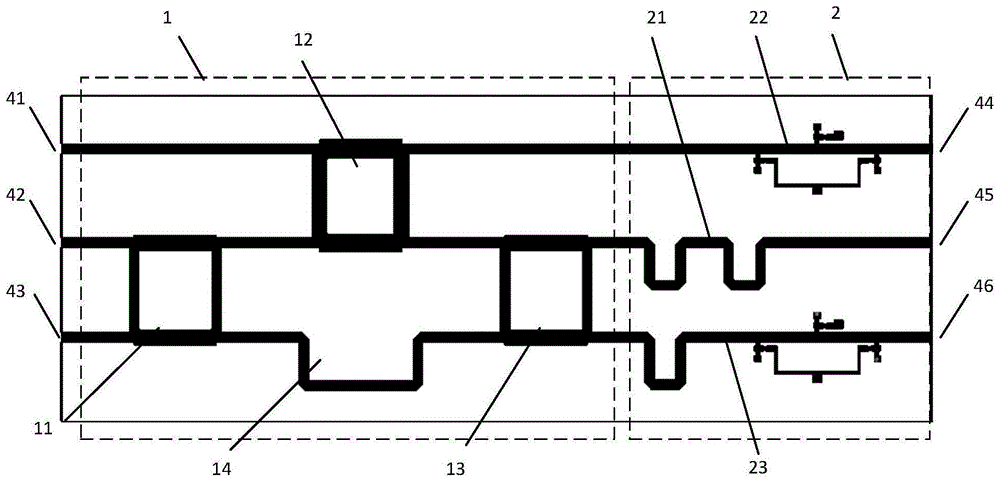
参照图1和图2,本实施例提供了一种连续可调的3×3 Nolen矩阵馈电网络,该网络包括一层介质板31,介质板31的上层为金属微带线层32,下层为金属接地层33,金属微带线层32上形成有两个部分,第一部分是3×3 Nolen矩阵1,第二部分是连续可调移相器组2;所述3×3 Nolen矩阵1由四个单元组成,分别是第一3dB耦合器11、4.77dB耦合器12、第二3dB耦合器13和-90°移相器14;所述连续可调移相器组2由三个单元组成,分别是第一连续可调移相器22、0°相对相位线21和第二连续可调移相器23;金属微带线层32左侧形成有三个馈电端口,分别为第一馈电端口41、第二馈电端口42和第三馈电端口43,右侧形成有三个输出端口44、45和46,第一馈电端口41连接4.77dB耦合器12左上输入端,第二馈电端口42连接第一3dB耦合器11左上输入端,第三馈电端口连接第一3dB耦合器11左下输入端,第一3dB耦合器11右上输出端连接4.77dB耦合器12左下输入端,第一3dB耦合器11右下输出端与-90°移相器14相连后再连接第二3dB耦合器13左下输入端,4.77dB耦合器12右下输出端连接第二3dB耦合器13左上输入端;所述3×3 Nolen矩阵1的三个输出端分别为4.77dB耦合器12右上输出端、第二3dB耦合器13右上输出端、第二3dB耦合器13右下输出端,这三个输出端分别连接连续可调移相器组2的三个输入端,即4.77dB耦合器右12上输出端通过后面的微带线连接第一连续可调移相器22的输入端,第二3dB耦合器13右上输出端连接0°相对相位线21输入端,第二3dB耦合器13右下输出端连接第二连续可调移相器23的输入端;连续可调移相器组2的三个输出端作为整个网络的三个输出端口44、45和46。Referring to Fig. 1 and Fig. 2, this embodiment provides a kind of continuously adjustable 3 * 3 Nolen matrix feed network, this network comprises a layer of dielectric board 31, the upper layer of dielectric board 31 is metal microstrip line layer 32, the lower layer It is a metal ground layer 33, and two parts are formed on the metal microstrip line layer 32, the first part is a 3×3 Nolen matrix 1, and the second part is a continuously adjustable phase shifter group 2; the 3×3 Nolen matrix 1 Consists of four units, namely the first 3dB coupler 11, the 4.77dB coupler 12, the second 3dB coupler 13 and the -90° phase shifter 14; the continuously adjustable phase shifter group 2 consists of three units The components are respectively the first continuously adjustable phase shifter 22, the 0° relative phase line 21 and the second continuously adjustable phase shifter 23; three feeding ports are formed on the left side of the metal microstrip line layer 32, which are respectively the first Feed port 41, the second feed port 42 and the third feed port 43, the right side is formed with three output ports 44, 45 and 46, the first feed port 41 is connected to the upper left input end of 4.77dB coupler 12, the second The feed port 42 is connected to the upper left input end of the first 3dB coupler 11, the third feed port is connected to the lower left input end of the first 3dB coupler 11, and the upper right output end of the first 3dB coupler 11 is connected to the lower left input end of the 4.77dB coupler 12, The lower right output of the first 3dB coupler 11 is connected to the -90° phase shifter 14 and then connected to the lower left input of the second 3dB coupler 13, and the lower right output of the 4.77dB coupler 12 is connected to the upper left input of the second 3dB coupler 13 terminal; the three output terminals of the 3×3 Nolen matrix 1 are respectively the upper right output terminal of the 4.77dB coupler 12, the upper right output terminal of the second 3dB coupler 13, and the lower right output terminal of the second 3dB coupler 13, these three The output ends are respectively connected to the three input ends of the continuously adjustable phase shifter group 2, that is, the upper output end of the right 12 of the 4.77dB coupler is connected to the input end of the first continuously adjustable phase shifter 22 through the microstrip line at the back, and the second 3dB coupler 13 upper right output end is connected with 0 ° relative phase line 21 input ends, the second 3dB coupler 13 lower right output end is connected with the input end of the second continuously adjustable phase shifter 23; Continuously adjustable phase shifter group 2 The three outputs serve as the three output ports 44, 45 and 46 of the entire network.
参照图3,3dB耦合器11和13采用同样的结构,当有信号从3dB耦合器11/13左侧上输入端输入时,在右侧的两个输出端将会输出等幅度的相位差为-90°的信号;当有信号从3dB耦合器11/13左侧下输入端输入时,在右侧的两个输出端将会输出等幅度的相位差为+90°的信号。Referring to Fig. 3,
参照图4,为4.77dB耦合器12,当有信号从4.77dB耦合器12左侧上输入端输入时,在右侧的两个输出端将会输出幅度上比下为1:

参照图5,为-90°移相器14,当有信号从左侧输入时,将从右侧输出移相为-90°的信号。Referring to FIG. 5, it is a -90°
参照图6,为0°相对相位线21,当有信号从左侧输入时,将从右侧输出相对移相为0°的信号。Referring to FIG. 6, it is a 0°
参照图7和图8,为第一连续可调移相器22和第二连续可调移相器23。两者采用的结构大体相似。第一连续可调移相器22包括-90°移相线221,三个隔直电容222,三个变容二极管223,三个金属接地通孔224,三个射频扼流圈电感225,第一个调节电压连接处226和第二个调节电压连接处227。其中金属接地通孔224的剖视图参照图2的34所示。第二连续可调移相器23包括-180°移相线231,三个隔直电容232,三个变容二极管233,三个金属接地通孔234,三个射频扼流圈电感235,第一个调节电压连接处236和第二个调节电压连接处237。其中金属接地通孔234的剖视图参照图2中34所示。当有信号从连续可调移相器22左侧输入端输入时,通过调节电压可以在右侧输出端产生移相为0°~90°的输出信号,当有信号从连续可调移相器23左侧输入端输入时,通过调节电压可以在右侧输出端产生移相为0°~-90°的输出信号,因此当有等幅等相位的信号输入连续可调移相器组2的三个输入端时,通过调节电压可以在三个输出端产生相位差为0°~90°的信号。Referring to FIG. 7 and FIG. 8 , there are a first continuously
参照图9,为可调3×3馈电网络的原理图。其中第二连续可调移相器23中的-90度移相器是由图7和图8中的-90°移相线221和-180°移相线231这两者的移相效果相减等效而来。Referring to FIG. 9 , it is a schematic diagram of an adjustable 3×3 feed network. Wherein the -90 degree phase shifter in the second continuously
参考图10,为第一连续可调移相器22和第二连续可调移相器23的内部相同单元连续可调移相器单元228/238的原理图。即第一连续可调移相器22的内部单元228和第二连续可调移相器23的内部单元238采用的相同结构。原理是通过在一段传输线上的特定位置处接入可以由电压调控的变容二极管,使得该单元的特性阻抗和电长度可以和一段固定特性阻抗且固定长度的传输线等效。调节两个控制电压控制电容值变化可以使得该单元所等效的传输线的特性阻抗保持50Ω不变,且电长度连续变化,变化范围为90°。这里是在一段微带线的三个间隔为65°电长度的点的位置接入了隔直电容与变容二极管串联的支路,该支路末端通过金属通孔接地,变容二极管与隔直电容之间接入与射频扼流圈串联的控制电压。其中两端的控制电压相同,且与中间的控制电压不同。图中C1、C2和C3为三个隔直电容222/232,采用200pf贴片电容,D1、D2和D3为三个变容二极管223/233,采用SMV1232-079LF,L1、L2和L3为三个射频扼流圈225/235,采用270nh贴片电感,V1为控制D1和D3的电压,V2为控制D2的电压。应当注意的是,第一连续可调移相器22和第二连续可调移相器23的两组控制电压是不同的,第一连续可调移相器22的控制电压变化使其移相相位增加(电长度减小),第二连续可调移相器23的控制电压变化使其移相相位减小(电长度增大)。Referring to FIG. 10 , it is a schematic diagram of the continuous adjustable
参考图11,为第一连续可调移相器22和第二连续可调移相器23的内部的相同单元连续可调移相器228/238在不同状态下移相相位的曲线图。可以看出,在2.45GHz处,该单元的电长度变化为-45°~45°的90°连续变化范围,即移相相位为45°~-45°的90°连续变化范围。图中给出了七种该连续可调移相器单元的状态,在2.45GHz处移相相位分别为45°、30°、15、0°、-15°、-30°、-45°。Referring to FIG. 11 , it is a graph of phase shifting of the same unit continuous
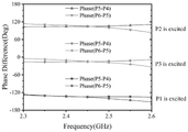
参考图12,为连续可调移相器组2在三种不同状态下三个输出端口之间的相位差的曲线图。三种状态下连续可调移相器组2的三个输出端口之间的相位差在2.45GHz处分别为0°、-45°、-90°。Referring to FIG. 12 , it is a graph of the phase difference between the three output ports of the continuously adjustable
在初始状态下,连续可调移相器组2的三个输出端相位差
进一步,在连续调节相位的状态下,连续可调移相器组2的三个输出端相位差

下面以连续可调移相器组2的三种状态给出可调3×3馈电网络的输出结果。The output results of the adjustable 3×3 feed network are given below with the three states of the continuously adjustable
参照图13、图14和图15,分别为当连续可调移相器组2的三个输出端相位差
参照图16、图17和图18,分别为当连续可调移相器组2的三个输出端相位差
参照图19、图20和图21,分别为当连续可调移相器组2的三个输出端相位差
参照下表1,为3×3 Nolen矩阵馈电网络各个输入端口输入时各输出端口的相位差与连续可调移相器组的输出相位差
参照下表2,为3×3 Nolen矩阵馈电网络中连续可调移相器组在仿真下所需的两组控制电压与输出相位差
表1Table 1
表2Table 2

上述实施例为本发明较佳的实施方式,但本发明的实施方式并不受上述实施例的限制,其他的任何未背离本发明的精神实质与原理下所作的改变、修饰、替代、组合、简化,均应为等效的置换方式,都包含在本发明的保护范围之内。The above-mentioned embodiment is a preferred embodiment of the present invention, but the embodiment of the present invention is not limited by the above-mentioned embodiment, and any other changes, modifications, substitutions, combinations, Simplifications should be equivalent replacement methods, and all are included in the protection scope of the present invention.
Claims (3)

Priority Applications (1)
| Application Number | Priority Date | Filing Date | Title |
|---|---|---|---|
| CN202111009899.XA CN113809552B (en) | 2021-08-31 | 2021-08-31 | Continuously adjustable 3 x 3Nolen matrix feed network |
Applications Claiming Priority (1)
| Application Number | Priority Date | Filing Date | Title |
|---|---|---|---|
| CN202111009899.XA CN113809552B (en) | 2021-08-31 | 2021-08-31 | Continuously adjustable 3 x 3Nolen matrix feed network |
Publications (2)
| Publication Number | Publication Date |
|---|---|
| CN113809552A CN113809552A (en) | 2021-12-17 |
| CN113809552B true CN113809552B (en) | 2022-11-18 |
Family
ID=78942167
Family Applications (1)
| Application Number | Title | Priority Date | Filing Date |
|---|---|---|---|
| CN202111009899.XA Expired - Fee Related CN113809552B (en) | 2021-08-31 | 2021-08-31 | Continuously adjustable 3 x 3Nolen matrix feed network |
Country Status (1)
| Country | Link |
|---|---|
| CN (1) | CN113809552B (en) |
Families Citing this family (2)
| Publication number | Priority date | Publication date | Assignee | Title |
|---|---|---|---|---|
| CN115548684B (en) * | 2022-09-29 | 2025-07-25 | 大连海事大学 | Broadband 4x 4Nolen matrix with adjustable phase among output ports and flatness |
| CN116565544B (en) * | 2023-06-26 | 2024-01-26 | 合肥工业大学 | Polarization and wave beam reconfigurable patch array antenna adopting geometric phase preset technology |
Family Cites Families (4)
| Publication number | Priority date | Publication date | Assignee | Title |
|---|---|---|---|---|
| EP3024297B1 (en) * | 2013-07-12 | 2020-10-14 | Guangdong Broadradio Communication Technology Co. Ltd. | 3x3 butler matrix and 5x6 butler matrix |
| US11855680B2 (en) * | 2013-09-06 | 2023-12-26 | John Howard | Random, sequential, or simultaneous multi-beam circular antenna array and beam forming networks with up to 360° coverage |
| CN110838621B (en) * | 2019-11-19 | 2020-11-20 | 北京邮电大学 | Multi-beam antenna feeding device and method |
| CN113036436B (en) * | 2021-03-02 | 2022-06-14 | 电子科技大学 | Miniaturized reconfigurable beam forming network architecture |
-
2021
- 2021-08-31 CN CN202111009899.XA patent/CN113809552B/en not_active Expired - Fee Related
Also Published As
| Publication number | Publication date |
|---|---|
| CN113809552A (en) | 2021-12-17 |
Similar Documents
| Publication | Publication Date | Title |
|---|---|---|
| Denidni et al. | Wide band four-port Butler matrix for switched multibeam antenna arrays | |
| CN115117615B (en) | Double-circularly-polarized flat plate electric scanning antenna based on 2bit phase digitization | |
| CN110829010B (en) | A dual circularly polarized beam reconfigurable microstrip antenna | |
| US10361485B2 (en) | Tripole current loop radiating element with integrated circularly polarized feed | |
| CN111786058B (en) | Low-loss phase shifter | |
| US12294153B2 (en) | Array antenna | |
| CN113809552B (en) | Continuously adjustable 3 x 3Nolen matrix feed network | |
| JPH03166803A (en) | Microstrip antenna for separately feeding two-frequency circular polarized wave | |
| CN113594704A (en) | Broadband triple-polarization reconfigurable high-gain microstrip antenna | |
| CN207705389U (en) | It is a kind of based on the compact aerial array for going here and there and presenting network | |
| CN116565544B (en) | Polarization and wave beam reconfigurable patch array antenna adopting geometric phase preset technology | |
| Talbi et al. | A compact 4× 4 butler matrix for UWB applications | |
| CN120109494B (en) | A frequency, polarization, and pattern reconfigurable antenna element and array | |
| CN214477928U (en) | A millimeter-wave multi-beam antenna based on 7×8 Butler matrix | |
| CN115548684B (en) | Broadband 4x 4Nolen matrix with adjustable phase among output ports and flatness | |
| CN114498022B (en) | Antenna structure and electronic equipment | |
| CN214099925U (en) | antenna array | |
| Orakwue et al. | Cascaded Butler matrix with two-dimensional beam scanning capability at 28 GHz for 5G wireless system | |
| CN102420351A (en) | Power dividing phase shifter | |
| CN222282244U (en) | Antenna device of electronically controlled third-order phase shifter and third-order phase shifter | |
| Temga et al. | 28GHz-band 2x2 patch antenna module vertically integrated with a compact 2-D BFN in broadside coupled stripline structure | |
| US20250357665A1 (en) | Antenna device with electronically controlled three-stage phase shifter and three-stage phase shifter | |
| Al-Zayed et al. | Five ports power divider designs with controllable power division and switching capabilities | |
| Kim et al. | A center-fed beam-steerable series antenna array with a wide matching bandwidth | |
| Afonin et al. | Antenna array of patch radiators with controlled polarization |
Legal Events
| Date | Code | Title | Description |
|---|---|---|---|
| PB01 | Publication | ||
| PB01 | Publication | ||
| SE01 | Entry into force of request for substantive examination | ||
| SE01 | Entry into force of request for substantive examination | ||
| GR01 | Patent grant | ||
| GR01 | Patent grant | ||
| CF01 | Termination of patent right due to non-payment of annual fee | ||
| CF01 | Termination of patent right due to non-payment of annual fee |
Granted publication date: 20221118 |