CN113748554A - Method for manufacturing all-solid-state battery and all-solid-state battery manufactured by using same - Google Patents
Method for manufacturing all-solid-state battery and all-solid-state battery manufactured by using same Download PDFInfo
- Publication number
- CN113748554A CN113748554A CN202080031316.0A CN202080031316A CN113748554A CN 113748554 A CN113748554 A CN 113748554A CN 202080031316 A CN202080031316 A CN 202080031316A CN 113748554 A CN113748554 A CN 113748554A
- Authority
- CN
- China
- Prior art keywords
- battery
- solid
- fluid
- solid battery
- jig
- Prior art date
- Legal status (The legal status is an assumption and is not a legal conclusion. Google has not performed a legal analysis and makes no representation as to the accuracy of the status listed.)
- Pending
Links
Images


Classifications
-
- H—ELECTRICITY
- H01—ELECTRIC ELEMENTS
- H01M—PROCESSES OR MEANS, e.g. BATTERIES, FOR THE DIRECT CONVERSION OF CHEMICAL ENERGY INTO ELECTRICAL ENERGY
- H01M10/00—Secondary cells; Manufacture thereof
- H01M10/05—Accumulators with non-aqueous electrolyte
- H01M10/058—Construction or manufacture
-
- H—ELECTRICITY
- H01—ELECTRIC ELEMENTS
- H01M—PROCESSES OR MEANS, e.g. BATTERIES, FOR THE DIRECT CONVERSION OF CHEMICAL ENERGY INTO ELECTRICAL ENERGY
- H01M4/00—Electrodes
- H01M4/02—Electrodes composed of, or comprising, active material
- H01M4/04—Processes of manufacture in general
- H01M4/0438—Processes of manufacture in general by electrochemical processing
- H01M4/044—Activating, forming or electrochemical attack of the supporting material
- H01M4/0445—Forming after manufacture of the electrode, e.g. first charge, cycling
- H01M4/0447—Forming after manufacture of the electrode, e.g. first charge, cycling of complete cells or cells stacks
-
- H—ELECTRICITY
- H01—ELECTRIC ELEMENTS
- H01M—PROCESSES OR MEANS, e.g. BATTERIES, FOR THE DIRECT CONVERSION OF CHEMICAL ENERGY INTO ELECTRICAL ENERGY
- H01M10/00—Secondary cells; Manufacture thereof
- H01M10/04—Construction or manufacture in general
- H01M10/0481—Compression means other than compression means for stacks of electrodes and separators
-
- H—ELECTRICITY
- H01—ELECTRIC ELEMENTS
- H01M—PROCESSES OR MEANS, e.g. BATTERIES, FOR THE DIRECT CONVERSION OF CHEMICAL ENERGY INTO ELECTRICAL ENERGY
- H01M10/00—Secondary cells; Manufacture thereof
- H01M10/05—Accumulators with non-aqueous electrolyte
- H01M10/058—Construction or manufacture
- H01M10/0585—Construction or manufacture of accumulators having only flat construction elements, i.e. flat positive electrodes, flat negative electrodes and flat separators
-
- H—ELECTRICITY
- H01—ELECTRIC ELEMENTS
- H01M—PROCESSES OR MEANS, e.g. BATTERIES, FOR THE DIRECT CONVERSION OF CHEMICAL ENERGY INTO ELECTRICAL ENERGY
- H01M10/00—Secondary cells; Manufacture thereof
- H01M10/42—Methods or arrangements for servicing or maintenance of secondary cells or secondary half-cells
- H01M10/44—Methods for charging or discharging
- H01M10/446—Initial charging measures
-
- H—ELECTRICITY
- H01—ELECTRIC ELEMENTS
- H01M—PROCESSES OR MEANS, e.g. BATTERIES, FOR THE DIRECT CONVERSION OF CHEMICAL ENERGY INTO ELECTRICAL ENERGY
- H01M10/00—Secondary cells; Manufacture thereof
- H01M10/05—Accumulators with non-aqueous electrolyte
- H01M10/056—Accumulators with non-aqueous electrolyte characterised by the materials used as electrolytes, e.g. mixed inorganic/organic electrolytes
- H01M10/0561—Accumulators with non-aqueous electrolyte characterised by the materials used as electrolytes, e.g. mixed inorganic/organic electrolytes the electrolyte being constituted of inorganic materials only
- H01M10/0562—Solid materials
-
- H—ELECTRICITY
- H01—ELECTRIC ELEMENTS
- H01M—PROCESSES OR MEANS, e.g. BATTERIES, FOR THE DIRECT CONVERSION OF CHEMICAL ENERGY INTO ELECTRICAL ENERGY
- H01M50/00—Constructional details or processes of manufacture of the non-active parts of electrochemical cells other than fuel cells, e.g. hybrid cells
- H01M50/10—Primary casings, jackets or wrappings of a single cell or a single battery
- H01M50/102—Primary casings, jackets or wrappings of a single cell or a single battery characterised by their shape or physical structure
- H01M50/105—Pouches or flexible bags
-
- Y—GENERAL TAGGING OF NEW TECHNOLOGICAL DEVELOPMENTS; GENERAL TAGGING OF CROSS-SECTIONAL TECHNOLOGIES SPANNING OVER SEVERAL SECTIONS OF THE IPC; TECHNICAL SUBJECTS COVERED BY FORMER USPC CROSS-REFERENCE ART COLLECTIONS [XRACs] AND DIGESTS
- Y02—TECHNOLOGIES OR APPLICATIONS FOR MITIGATION OR ADAPTATION AGAINST CLIMATE CHANGE
- Y02E—REDUCTION OF GREENHOUSE GAS [GHG] EMISSIONS, RELATED TO ENERGY GENERATION, TRANSMISSION OR DISTRIBUTION
- Y02E60/00—Enabling technologies; Technologies with a potential or indirect contribution to GHG emissions mitigation
- Y02E60/10—Energy storage using batteries
-
- Y—GENERAL TAGGING OF NEW TECHNOLOGICAL DEVELOPMENTS; GENERAL TAGGING OF CROSS-SECTIONAL TECHNOLOGIES SPANNING OVER SEVERAL SECTIONS OF THE IPC; TECHNICAL SUBJECTS COVERED BY FORMER USPC CROSS-REFERENCE ART COLLECTIONS [XRACs] AND DIGESTS
- Y02—TECHNOLOGIES OR APPLICATIONS FOR MITIGATION OR ADAPTATION AGAINST CLIMATE CHANGE
- Y02P—CLIMATE CHANGE MITIGATION TECHNOLOGIES IN THE PRODUCTION OR PROCESSING OF GOODS
- Y02P70/00—Climate change mitigation technologies in the production process for final industrial or consumer products
- Y02P70/50—Manufacturing or production processes characterised by the final manufactured product
Abstract
The present application is directed to providing a method of applying a fixed pressure to an all-solid battery during the activation of the all-solid battery and preventing an interfacial contact surface from being separated due to gas generated in the all-solid battery, and an all-solid battery manufactured using the same.
Description
Technical Field
The present application claims priority from korean patent application No.2019-0053691, filed on 8/5/2019, the disclosure of which is incorporated herein by reference in its entirety.
The present invention relates to a method of manufacturing an all-solid battery and an all-solid battery manufactured using the same, and more particularly, to a method of manufacturing an all-solid battery including a process of disposing a fluid between an all-solid battery and a jig upon activation.
Background
With the development of Electric Vehicles (EVs), Hybrid Electric Vehicles (HEVs) and plug-in hybrid electric vehicles (plug-in HEVs) in addition to mobile devices and home appliances, it is expected that the demand of lithium secondary batteries will continue to increase. An all-solid-state battery exhibiting high stability and energy density and a long life is a technology capable of forming a new market for lithium secondary batteries.
Generally, a secondary battery undergoes an activation process at the time of manufacture. The activation process includes a process of applying a current to the battery to a predetermined voltage and discharging the battery. During the initial charge and discharge, a protective film is formed on the electrode surface and the electrolyte is decomposed, thereby generating a large amount of gas. The gas may cause failure of the battery cell and may increase the volume of the battery cell. Therefore, the battery is assembled in a state where the generated gas is removed, thereby producing a finished product of the battery.
Various methods are contemplated to remove the gas. There is a method of providing an air pocket to remove gas based on the natural pressure differential from inside the battery cell and a chemical method of adding a material that can reduce gas generation. However, in the method of removing gas based on a natural pressure difference, the gas is not sufficiently removed, and the chemical method may interfere with the chemical reaction in the battery.
In the case where the battery swells due to gas during activation, the performance of the battery suddenly deteriorates due to interface separation. Many studies have been made on a method of physically solving the problem in order to improve the performance of the battery. A method of performing an activation process in a state where the battery cells 200 are placed in the jigs 100 and 110 and the predetermined pressures 300 and 310 are applied to the battery cells as shown in fig. 1 is also considered. In the case where uniform pressure is not applied to the battery, the life of the battery may be shortened. For an all-solid battery, the electrolyte is also in a solid state, and thus the surface of the battery may not be uniform in many cases, and the external pressure is not uniformly distributed due to the nature of its material.
The detailed technique and object of patent document 2 also differ from the present invention in that pressure is continuously applied to the battery during use of the battery after activation. Separate space is required to dispose the plate and the pressurizing unit in the housing, and the outer housing must be rigid in order to maintain the pressure. The pressurizing unit is configured such that a middle portion thereof is first expanded, and a sectional thickness of the pressurizing unit is gradually reduced from the middle portion to opposite ends thereof after a predetermined amount of air is injected. As a result, uniform pressure cannot be applied to the battery cells having various shapes.
As described above, various techniques capable of applying pressure to the electrode assembly in order to reduce internal resistance during use of the battery after activation have been proposed. For the all-solid battery, interface contact defects frequently occur, and thus various techniques related to pressurization have been applied to the all-solid battery.
In the case of an all-solid battery, the performance of the battery may be degraded due to its deformation during activation due to its uneven external shape; however, a method of identifying such a problem and solving the problem during activation of the all-solid battery has not been proposed.
(patent document 1) International application publication No. 2013-008321 (2013.01.17)
(patent document 2) Korean patent application laid-open No. 2016 + 0001399 (2016.01.06)
(patent document 3) Japanese patent laid-open No. 2012-151080 (2012.08.09)
(patent document 4) Japanese patent laid-open No. 2008-147010 (2006.06.26)
Disclosure of Invention
Technical problem
The present invention has been made in view of the above problems, and it is an object of the present invention to provide a method of applying uniform pressure to an all-solid battery during the activation of the all-solid battery and preventing interfacial contact surfaces from being separated due to gas generated in the all-solid battery, thereby extending the life of the battery, and an all-solid battery manufactured using the same.
Technical scheme
In order to achieve the above object, the present invention provides a method of manufacturing an all-solid battery including a positive electrode, a negative electrode, and a solid electrolyte, the method including the steps of:
a) coupling the positive electrode, the negative electrode and the solid electrolyte to manufacture an all-solid battery;
b) placing the all-solid-state battery manufactured in step a) in a jig;
c) disposing a fluid between at least one surface of the all-solid battery and the clamp;
d) fixing the all-solid-state battery using the jig; and
e) charging and discharging the all-solid battery to activate the all-solid battery.
Further, steps b) and c) may be performed in this order, simultaneously or in reverse order.
Furthermore, the method comprises placing the all-solid-state battery in a pouch or can after step a).
Further, step e) is to perform charging and discharging a predetermined number of times.
The method may further comprise removing the fluid and performing additional charging and discharging after step e).
Further, when the charge and discharge are performed, at (CC/CV): charging was performed under the condition of 0.05C/4.15V, 0.02C off, rest for 30 minutes, at (CC): the discharge was performed under the condition of 0.05C, 3V off.
Further, the fluid may be a gas or a liquid.
Furthermore, the fluid may be uniformly distributed between the jig and the entire surface of the all-solid battery adjacent to the jig.
Further, the fluid is contained in a separate sealed bag.
Further, the fluid is uniformly distributed between the jig and the entire opposite surface of the all-solid battery abutting the jig in a state that it can be contained in a single sealed bag.
Further, the sealing bag may be made of a material exhibiting elasticity to such an extent that the bag is not damaged by the pressure from the jig and the fluid in the bag distributes the pressure from the jig uniformly between the jig and the entire surface of the all-solid battery adjacent to the jig.
Furthermore, the sealed bag may be provided with means configured to add gas or liquid by replenishment.
Additionally, the sealed bag may be attached to one surface of the clamp.
Furthermore, the method may further comprise sealing the bag or the canister after the activation step of step e) is completed.
Furthermore, an all-solid battery can be manufactured using the method according to any one of claims 1 to 13.
In the present invention, individual applications of the above-described solutions or various possible combinations thereof are possible.
Drawings
Fig. 1 is a schematic view showing an all-solid battery having an uneven surface and pressure applied to the all-solid battery from a jig at the time of a conventional activation process.
Fig. 2 is a schematic diagram showing an all-solid battery configured such that a part of its surface protrudes and pressure applied to the all-solid battery from a jig at the time of a conventional activation process.
Fig. 3 is a schematic diagram showing an oval-shaped all-solid battery and pressure applied to the all-solid battery from a jig during a conventional activation process.
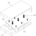
Fig. 4 is a schematic view showing an all-solid battery having an uneven surface and a pressure applied to the all-solid battery from a jig at the time of an activation process according to the present invention.
Fig. 5 is a schematic diagram showing an all-solid battery configured such that a part of its surface protrudes and pressure applied to the all-solid battery from a jig at the time of an activation process according to the present invention.
Fig. 6 is a schematic diagram showing an elliptical all-solid battery and pressure applied to the all-solid battery from a jig at the time of activation according to the present invention.
Fig. 7 is a graph showing the capacity of batteries according to examples of the present invention and comparative examples at the time of initial charge and discharge.
Fig. 8 is a graph showing the capacity of batteries according to an example of the present invention and a comparative example when charging and discharging are performed 10 times.
Detailed Description
Now, preferred embodiments of the present invention will be described in detail with reference to the accompanying drawings so that those skilled in the art to which the present invention pertains can easily implement the preferred embodiments of the present invention. However, in describing in detail the operational principle of the preferred embodiments of the present invention, a detailed description of known functions and configurations incorporated herein will be omitted when it may obscure the subject matter of the present invention.
Further, the same reference numerals are used throughout the drawings to designate components that perform similar functions or operations. In the case where one component is referred to as being connected to another component in the specification, not only may the one component be directly connected to the other component, but also the one component may be indirectly connected to the other component via the other component. Furthermore, the inclusion of certain elements is not meant to exclude other elements, but rather, is meant to further include such elements unless otherwise stated.
Hereinafter, the present invention will be described in more detail.
The present invention provides a method of manufacturing an all-solid battery including a positive electrode, a negative electrode, and a solid electrolyte, the method including the steps of:
a) coupling the positive electrode, the negative electrode and the solid electrolyte to manufacture an all-solid battery;
b) placing the all-solid-state battery manufactured in step a) in a jig;
c) disposing a fluid between at least one surface of the all-solid battery and the clamp;
d) fixing the all-solid-state battery using the jig; and
e) and charging and discharging the all-solid-state battery.
The all-solid battery is configured such that a surface of the all-solid battery, which does not include the electrode, abuts the jig. To prevent the battery from swelling, all surfaces of the battery except for the electrodes may be abutted with the jig.
The fluid may be disposed between one surface of the all-solid battery and the clamp, or may be disposed between an opposite surface of the all-solid battery and the clamp. More preferably, the fluid is disposed between the opposite surface of the all-solid battery and the jig. In the case where the fluid is disposed between the opposite surfaces of the all-solid battery and the jig, uniform pressure may be applied to the opposite surfaces of the battery cells, and uniform pressure may also be applied to any of various shapes of battery cells. In the case where the fluid is provided between one surface of the all-solid battery and the jig, the fluid may exhibit viscosity to the extent that the fluid cannot move to the gap between the other surface of the all-solid battery and the jig. The clamp may be provided with a layer or step configured to prevent movement of the fluid. At this time, the fluid may be present in an area equal to or greater than the maximum surface area of the battery. In the case where the area of the fluid is smaller than the area of the cell, the pressure applied to the portion of the cell where the fluid is not provided varies. For this purpose, the fluid must be of such a magnitude that a uniform pressure is exerted on the cell housing.
The pressure applied to the all-solid battery must be 50kgf/cm2And 5000kgf/cm2In the meantime.
The pressure applied to the all-solid battery was 0.1kgf/cm2Or lower, the jig does not work normally, and thus the battery cell cannot be prevented from swelling due to gas. The pressure applied to the all-solid battery was 40kgf/cm2Or higher, the fluid does not work properly and thus does not apply a uniform force to the battery cellPressure and therefore the battery cells may be damaged.
The structure of the all-solid battery is not limited. The winding type structure, the stacking/folding type structure, and the step type structure in which a plurality of batteries are stacked in a single pouch may be applied to the all-solid battery. The all-solid battery may include a gas discharge port. The all-solid battery may be configured in a state in which a portion of the battery where the electrode is provided is partially temporarily sealed.
The kind of the all-solid battery is not limited, and any all-solid battery having high efficiency can be used without limitation.
Steps b) and c) may be performed in this order, simultaneously or in reverse order.
In the case where the all-solid battery and the fluid are simultaneously arranged in the jig, a step of protecting the electrodes so that the electrodes do not react with the fluid may be included. At this time, the electrode and the fluid may be introduced into the jig at different positions or the same position. The size of the jig is not limited as long as the electrodes and the fluid can be introduced into the jig. However, in the case where the fluid layer is made of gas or liquid, the jig may be configured to have a structure in which the gas or fluid layer cannot be discharged from the jig.
However, when the fluid is a gas or a liquid, the fixture has a fluid layer such that the gas or liquid cannot escape from the fluid layer.
The fixing mode of the jig is not limited as long as the jig can fix the fluid layer and the battery cell to each other. The clamp may have a shape similar to the shape of the battery cell or a shape different from the shape of the battery cell. The jig may have a structure capable of wrapping five surfaces out of six surfaces of the battery cell, or a structure capable of fixing only the widest upper and lower surfaces of the battery.
Further, a step of placing the all-solid battery in a pouch or can may be added after step a).
The bag or the can is not particularly limited. Preferably, however, the bag or canister is made of a material that exhibits low reactivity to the fluid. Typically, polyethylene, polypropylene, polycarbonate or aluminum laminates may be included.
The bag or can may include a coating to reduce reactivity with the fluid. The thickness of the coating layer is not particularly limited as long as the coating layer can reduce the reaction between the fluid and the case without reducing the capacity of the battery. The coating may include inert particles. The inert particles may be organic particles and/or inorganic particles, but the inert particles are not limited. In case the inert particles are organic particles, the inert particles may be polymers or silane based compounds. For example, the polymer may be PE, PP, PS, PVdF, PTFE, PET, PMMA, or PANdIf, and the silane-based compound may be Hexamethyldisilazane (HMDS), Trimethylchlorosilane (TMSCL), Polydimethylsiloxane (PDMS), or dimethyldichlorosilane (DDS). For example, the inorganic particles may be selected from the group consisting of SiO2、Al2O3、MgO、TiO2、ZrO2、CaO、Y2O3And SrO. The coating may have a thickness of 1 μm to 160 μm. In the case where the thickness of the coating layer is 1 μm or less, the material in the coating layer is not distributed properly, and thus the coating layer may not function properly, which is not desirable. In the case where the thickness of the coating layer is 160 μm or more, the space efficiency of the battery is reduced as compared with the effect of the battery, which is also undesirable. Further, an outer resin layer may be added instead of/together with the coating layer. The outer resin layer may be made of a polyolefin-based resin exhibiting low reactivity with the fluid. More preferably, the outer resin layer is made of polypropylene.
The shape and roughness of the surface of the bag or can are not limited. The surface may be rough, or a portion of the surface may be convex or concave. As shown in fig. 4, the roughness of the surface may be as fine as the surface is roughened when processing the material, or as shown in fig. 5, the surface may have a convex-concave portion configured to allow the battery cell to be coupled to another battery cell or an external device. Further, the shape of the bag or can is not limited. The method of manufacturing an all-solid battery according to the present invention may be applied to an oval can (as shown in fig. 6), a prismatic can, or a can having any of various structures (e.g., a stepped structure).
Further, step e) is a step of performing charging and discharging a predetermined number of times.
A step of removing the fluid and performing additional charging and discharging may be further added after step e).
The charging and discharging may be performed one to ten times in the presence of the fluid. In addition, the charging and discharging may be performed one to ten times in a state where the fluid is not present. When the charge and discharge are performed 1 to 10 times, the charge and discharge may be performed all the time in a state where the fluid is present or absent, the charge and discharge may be performed a plurality of times in a state where the fluid is present, or the charge and discharge may be performed a plurality of times in a state where the fluid is absent.
Further, in charging and discharging, the charge density can be set at (CC/CV): charging was performed under the condition of 0.05C/4.15V, 0.02C off, rest for 30 minutes, at (CC): the discharge was performed under the condition of 0.05C, 3V off.
The above conditions are set to improve the charge/discharge efficiency, and the charge/discharge conditions are not limited to the above conditions as long as the charge/discharge is performed to improve the battery capacity.
Further, a step of sealing the bag or can may be further added after step e) (i.e., the activation step) is completed.
The bag or can may have a hot melt film for sealing. The hot melt film may include a film that may be at a temperature of 160 ℃ to 210 ℃ and 1 to 3kgf/cm2A material that melts thermally under pressure of (1). The hot melt film may have a thickness of 1 μm to 1nm and a width of 1nm to 20 nm. In the case where the hot-melt film is too narrow, it is difficult to achieve improvement of the sealing property due to hot-melting. On the other hand, in the case where the thickness or width of the hot melt film is too large, a step may be formed between the hot melt film and a sealing portion therearound, whereby sealability at an interface therebetween may be deteriorated. The material of the hot-melt film is not particularly limited as long as the material exhibits high moisture resistance and hot-melt property. Polyethylene and polypropylene (which are polyolefin-based polymer resins) and combinations thereof may be mentioned as examples.
The bag or can may be sealed by ultrasonic or laser metal welding. The bag or can may be sealed by pressing using a ball mill.
In the case of a pouch-shaped all-solid battery, a step of folding the pouch case may be included after the sealing step. The pouch-shaped all-solid battery may be formed in a shape having no angled portion.
In addition, the fluid may be a gas, a liquid, or a movable solid, and the range of the fluid may be changed without limitation as long as the fluid can absorb pressure from the jig. Preferably, however, the fluid is a gas to improve the performance of the cell when uniform pressure is applied to the fixture. Furthermore, the fluid need not be composed of a single material. Some fluids may be gases, some fluids may be liquids, or fluids may include all of liquids, solids, and gases.
The fluid may be composed of a material that is inert or at least does not affect the performance of the cell. Here, the gas may be an inert gas. For example, the gas may include nitrogen or argon. Here, the liquid may be an inert liquid. Materials such as kerosene or naphtha may be mentioned as examples. In the case where the fluid is contained solely in the pouch, the fluid need not be an inert or at least a material that does not affect the performance of the cell.
Furthermore, the fluid may be uniformly distributed between the clamp and the surface of the all-solid battery that abuts the clamp.
The fluid may exhibit viscosity to the extent that pressure from the clamp is evenly distributed between the clamp and the entire surface of the all-solid battery that abuts the clamp.
The fluid may be a hydrophobic material that prevents moisture from penetrating the cell.
Further, the fluid may be contained in a separate sealed bag.
Further, in a state where the fluid is contained in a single sealed bag, the fluid can be uniformly distributed between the jig and the entire opposite surface of the all-solid battery, which is adjacent to the jig.
The fluid contained in the bag may be a gas or a liquid.
Further, the sealing pouch may be made of a material exhibiting elasticity to the extent that the pouch is not damaged by pressure from the jig and the fluid in the pouch evenly distributes the pressure from the jig between the jig and the entire surface of the all-solid battery adjacent to the jig.
The pressure may be 50kgf/cm2And 5000kgf/cm2In the meantime. Under a pressure of 50kgf/cm2Or lower, the bag absorbs the pressure, whereby the pressure from the clamp is not transmitted to the battery cells. Under a pressure of 40kgf/cm2Or lower, the battery cell may be damaged even if the pouch absorbs the pressure, or the predetermined pressure may not be transmitted to the battery cell.
The shape of the pouch is not limited, but is limited to a shape that can wrap all portions of the battery cell that may be abutted by the clamp. The bag may be made of an elastic polymer or rubber exhibiting high elasticity. The thickness of the bag must be set to such an extent that the bag does not interfere with the action of the fluid therein. In the case where the bag thickness is 10 μm or less, the bag cannot withstand the pressure. In the case where the thickness of the bag is 0.5cm or more, the effect of the fluid in the bag to uniformly transmit pressure may be deteriorated.
In the case where the clamps are disposed above and below the battery, the pouch may be disposed between the battery and the clamps. A case that the clamps are disposed at left and right sides of the battery may be included; however, a structure in which the clamps are disposed above and below the battery is preferable.
Furthermore, the sealed bag may be provided with means configured to add gas or liquid by replenishment. The supplementary device may be formed in a shape having an injection port. The supplementary device may have a structure capable of preventing the fluid from being discharged by the pressure of the jig.
The sealed bag may be made of a material that does not chemically react with the fluid.
The bag is not particularly limited. Preferably, however, the bag is made of a material that exhibits low reactivity to the fluid. Typically, polyethylene, polypropylene, polycarbonate or aluminum laminates may be included.
The bag may include a coating to reduce reactivity with the fluid. The thickness of the coating layer is not particularly limited as long as the coating layer can reduce the reaction with the fluid without reducing the capacity of the battery. The coating may include inert particles.The inert particles may be organic particles and/or inorganic particles, but the inert particles are not limited. In the case where the inert particles are organic particles, the inert particles may be a polymer or a silane-based compound. For example, the polymer may be PE, PP, PS, PVdF, PTFE, PET, PMMA, or PANdIf, and the silane-based compound may be Hexamethyldisilazane (HMDS), Trimethylchlorosilane (TMSCL), Polydimethylsiloxane (PDMS), or dimethyldichlorosilane (DDS). For example, the inorganic particles may be selected from the group consisting of SiO2、Al2O3、MgO、TiO2、ZrO2、CaO、Y2O3And SrO. The coating may have a thickness of 1 μm to 160 μm. In the case where the thickness of the coating layer is 1 μm or less, the material in the coating layer is not distributed properly, and thus the coating layer may not function properly, which is not desirable. In the case where the thickness of the coating layer is 160 μm or more, the space efficiency of the battery is reduced as compared with the effect of the battery, which is also undesirable. Further, an outer resin layer may be added instead of/together with the coating layer. The outer resin layer may be made of a polyolefin-based resin exhibiting low reactivity with the fluid. More preferably, the outer resin layer is made of polypropylene.
Additionally, the bag may be attached to one surface of the clip.
The bag is attached to one surface of the clamp to prevent the bag from moving due to gravity.
Fig. 1 is a schematic diagram illustrating an all-solid battery 200, the all-solid battery 200 having an uneven surface and pressures 300 and 310 applied to the all-solid battery 200 from clamps 100 and 110 during a conventional activation process. It can be seen that the pressure applied to the protruding portions of the surface is higher than the pressure applied to the recessed portions of the surface. In fig. 1 to 6, the pressures 300, 310 and 320 are represented by arrows having different sizes. In the case where the size of the arrow is large, the pressure is high. In the case where the size of the arrow is small, the pressure is low. In the case where the sizes of the arrows are equal to each other, the pressure is uniform. In contrast, during activation according to the present invention, as shown in fig. 4, the fluid layers 400 and 410 uniformly wrap the battery, thereby applying uniform pressure to the battery.
Fig. 2 is a schematic diagram showing the all-solid battery 210, the all-solid battery 210 being configured such that a part of the surface thereof protrudes, and the pressing forces 300 and 310 being applied to the all-solid battery 210 from the jigs 100 and 110 at the time of a normal activation process. Even in the case where the all-solid battery 210 has protrusions, the pressure applied to the protruding portions of the battery is higher than the planar portions of the battery. In contrast, during activation according to the present invention, as shown in fig. 5, the fluid layers 400 and 410 uniformly wrap the battery, thereby applying uniform pressure to the battery.
Fig. 3 is a schematic diagram showing an elliptical shape of the all-solid battery 220 and pressures 300 and 310 applied to the all-solid battery 220 from the clamps 100 and 110 at the time of a conventional activation process. In the case where the oval-shaped all-solid battery 220 is disposed in the planar jigs 100 and 110, the middle portion of the battery protrudes. Therefore, even in the case of the elliptical all-solid battery 220, pressure is applied to the middle of the battery. In contrast, during activation according to the present invention, as shown in fig. 6, the fluid layers 400 and 410 uniformly wrap the battery, thereby applying uniform pressure to the battery.
Hereinafter, the present invention will be described with reference to the following examples. These examples are provided only for easier understanding of the present invention and should not be construed as limiting the scope of the present invention.
Examples of the present invention will be described in detail with reference to the accompanying drawings.
< example >
The following examples and comparative examples were charged and discharged using the following methods.
In the examples and comparative examples, pouch-shaped battery cells configured such that a planar portion of each battery cell to which no individual shape or roughness is added is a rounded quadrangle and has a uniform height are used.
At the time of charging and discharging of each example and comparative example, in (CC/CV): charging was performed under the condition of 0.05C/4.15V, 0.02C off, rest for 30 minutes, at (CC): discharging at 0.05C and 3V, and applying 500kgf/C to the clampm2The pressure of (a). The jig is configured to have a shape to wrap all surfaces of the battery. The fluid pouch is configured to wrap around all surfaces of the battery cell. The fluid bag is configured to have a shape with a predetermined thickness. A fluid bag with a thickness of 75 μm was used.
In example 1, a fluid pouch containing atmospheric gases is disposed between a battery cell and a fixture.
In example 2, a fluid pouch containing water is disposed between the battery cell and the clamp.
In comparative example 1, nothing was left between the battery cell and the jig.
In comparative example 2, a silicon pad was disposed to wrap the entire upper and lower surfaces of the battery cell.
In comparative example 3, silicon pads were provided to wrap portions of the upper and lower surfaces of the battery cells.
Referring to fig. 7, the initial charge and discharge capacity of the batteries charged and discharged once according to the examples and comparative examples of the present invention was measured, and the pouch containing the gas had the highest charge and discharge capacity. The liquid-containing pouch has the second highest charge and discharge capacity. The battery capacity of comparative example 1, in which nothing is left between the battery cell and the jig, is the lowest.
These cases are meaningfully maintained even in the case where charging and discharging are performed 10 times.
As can be seen from fig. 8, even when the battery is charged and discharged ten times, the examples and comparative examples of the present invention have capacities in the same order as one charge and discharge.
While specific details of the invention have been described in detail, it will be appreciated by those skilled in the art that the detailed description thereof discloses only preferred embodiments of the invention and is therefore not to be taken as limiting the scope of the invention. Accordingly, it will be understood by those skilled in the art that various changes and modifications are possible without departing from the scope and technical spirit of the present invention, and it is apparent that such changes and modifications fall within the scope of the appended claims.
Description of the reference numerals
100. 110: clamp apparatus
200, 210, 220: all-solid-state battery
300. 310, 320: pressure exerted by the clamp
400. 410: fluid layer
Industrial applicability
As apparent from the above description, the present invention relates to a method of uniformly applying pressure to a battery between a battery cell and a jig when activating the battery, and has advantages in that uniform pressure is applied to the battery when activating and initial performance of the battery is improved, whereby the life span of the battery is longer than that of a conventional battery.
Claims (14)
1. A method of manufacturing an all-solid battery including a positive electrode, a negative electrode, and a solid electrolyte, the method comprising the steps of:
a) coupling the positive electrode, the negative electrode and the solid electrolyte to manufacture an all-solid battery;
b) placing the all-solid-state battery manufactured in step a) in a jig;
c) disposing a fluid between at least one surface of the all-solid battery and the clamp;
d) fixing the all-solid-state battery using the jig; and
e) charging and discharging the all-solid battery to activate the all-solid battery.
2. The method of claim 1, wherein steps b) and c) are performed in an original order, simultaneously, or in a reverse order.
3. The method of claim 2, further comprising: placing the all-solid-state battery in a pouch or can after step a).
4. The method of claim 1, wherein
Step e) is to perform charging and discharging for a predetermined number of times, and
the method further comprises the following steps: removing the fluid and performing additional charging and discharging after step e).
5. The method of claim 4, wherein when performing charging and discharging, the charge and discharge is performed at (CC/CV): charging was performed under the condition of 0.05C/4.15V, 0.02C off, rest for 30 minutes, at (CC): the discharge was performed under the condition of 0.05C, 3V off.
6. The method of claim 1, wherein the fluid is a gas or a liquid.
7. The method of claim 1, wherein the fluid is uniformly distributed between the clamp and an entire surface of the all-solid battery adjacent to the clamp.
8. The method of claim 1, wherein the fluid is contained in a separate sealed bag.
9. The method according to claim 8, wherein the fluid is uniformly distributed between the jig and the entire opposite surface of the all-solid battery abutting the jig in a state of being contained in a single sealed bag.
10. The method of claim 8, wherein the sealed pouch is made of a material that exhibits elasticity to an extent such that the pouch is not damaged by pressure from the clamp and fluid in the pouch evenly distributes pressure from the clamp between the clamp and the entire surface of the all-solid battery that abuts the clamp.
11. The method of claim 8, wherein the sealed bag is provided with a device configured to add gas or liquid by replenishment.
12. The method of claim 8, wherein the sealed bag is attached to one surface of the clamp.
13. The method of claim 3, further comprising: sealing the bag or the canister after completion of the activation step of step e).
14. An all-solid battery manufactured using the method according to any one of claims 1 to 13.
Applications Claiming Priority (3)
| Application Number | Priority Date | Filing Date | Title |
|---|---|---|---|
| KR1020190053691A KR20200129379A (en) | 2019-05-08 | 2019-05-08 | Method for manufacturing of All-Solid Battery and All-Solid Battery Prepared by the Same. |
| KR10-2019-0053691 | 2019-05-08 | ||
| PCT/KR2020/005223 WO2020226299A1 (en) | 2019-05-08 | 2020-04-20 | Method for manufacturing all-solid-state battery, and all-solid-state battery manufactured using same |
Publications (1)
| Publication Number | Publication Date |
|---|---|
| CN113748554A true CN113748554A (en) | 2021-12-03 |
Family
ID=73051106
Family Applications (1)
| Application Number | Title | Priority Date | Filing Date |
|---|---|---|---|
| CN202080031316.0A Pending CN113748554A (en) | 2019-05-08 | 2020-04-20 | Method for manufacturing all-solid-state battery and all-solid-state battery manufactured by using same |
Country Status (6)
| Country | Link |
|---|---|
| US (1) | US20220069277A1 (en) |
| EP (1) | EP3907806A4 (en) |
| JP (1) | JP7262721B2 (en) |
| KR (1) | KR20200129379A (en) |
| CN (1) | CN113748554A (en) |
| WO (1) | WO2020226299A1 (en) |
Families Citing this family (7)
| Publication number | Priority date | Publication date | Assignee | Title |
|---|---|---|---|---|
| EP4138170A1 (en) * | 2021-04-09 | 2023-02-22 | LG Energy Solution, Ltd. | Method for preparing all-solid-state battery and all-solid-state prepared thereby |
| US11631890B2 (en) * | 2021-05-06 | 2023-04-18 | Solid Energies Inc. | All solid-state lithium-ion battery produced by pressure-aided co-curing |
| KR102570543B1 (en) | 2021-05-26 | 2023-08-28 | (주)나노제네시스 | Anode for all-solid-state battery including graphene-metal nanoparticle composite and all-solid-state battery including the same |
| KR102581082B1 (en) * | 2021-11-26 | 2023-09-21 | (주)하나기술 | Pressurizing system of all solid state secondary battery |
| KR102449415B1 (en) | 2022-02-04 | 2022-10-11 | (주)바이오제네시스 | Anode For Lithium Ion Battery Containing Hybrid Graphene |
| KR102545573B1 (en) | 2022-09-27 | 2023-06-21 | (주)바이오제네시스 | Hybrid Graphene Composite Particles |
| KR102545572B1 (en) | 2022-09-27 | 2023-06-29 | (주)바이오제네시스 | Battery With Hybrid Graphene Anode |
Citations (11)
| Publication number | Priority date | Publication date | Assignee | Title |
|---|---|---|---|---|
| JPH0548210U (en) * | 1991-11-29 | 1993-06-25 | 日本電池株式会社 | Storage battery spacer |
| JP2001297798A (en) * | 2000-04-14 | 2001-10-26 | Nec Corp | Manufacturing method of flat battery |
| JP2008147010A (en) * | 2006-12-08 | 2008-06-26 | Nissan Motor Co Ltd | Power supply device, and its control method |
| JP2009295289A (en) * | 2008-06-02 | 2009-12-17 | Panasonic Corp | Lithium-ion secondary battery and method of manufacturing the same |
| JP2012221773A (en) * | 2011-04-11 | 2012-11-12 | Toyota Motor Corp | Solid-state battery, and solid-state battery system |
| KR20150050223A (en) * | 2013-10-31 | 2015-05-08 | 주식회사 엘지화학 | Pressure tray and Pressure jig applied for the same |
| KR20180025805A (en) * | 2016-09-01 | 2018-03-09 | 주식회사 엘지화학 | Pressing jig and method of fabricating secondary battery using the same |
| CN207282663U (en) * | 2017-07-11 | 2018-04-27 | 佛山市金广源电源科技有限公司 | A kind of charging system of all-solid-state battery |
| JP2018106984A (en) * | 2016-12-27 | 2018-07-05 | トヨタ自動車株式会社 | All-solid-state lithium ion battery |
| US20190006699A1 (en) * | 2013-01-16 | 2019-01-03 | Sion Power Corporation | Pressure and/or temperature management in electrochemical systems |
| WO2019054837A1 (en) * | 2017-09-18 | 2019-03-21 | 주식회사 엘지화학 | Method for manufacturing pouch type battery cell by using jig, comprising fixing step |
Family Cites Families (9)
| Publication number | Priority date | Publication date | Assignee | Title |
|---|---|---|---|---|
| JP5257471B2 (en) | 2010-12-28 | 2013-08-07 | トヨタ自動車株式会社 | battery |
| JP2012169204A (en) * | 2011-02-16 | 2012-09-06 | Toyota Motor Corp | Battery structure |
| JP5664783B2 (en) | 2011-07-13 | 2015-02-04 | トヨタ自動車株式会社 | Battery module |
| JP5754337B2 (en) * | 2011-10-11 | 2015-07-29 | トヨタ自動車株式会社 | Power storage device |
| KR20160001399A (en) | 2014-06-27 | 2016-01-06 | 주식회사 엘지화학 | Tray for secondary battery electrode assembly |
| JP6578590B2 (en) * | 2016-09-23 | 2019-09-25 | 株式会社エンビジョンAescジャパン | Method for producing film-clad battery |
| KR20190053691A (en) | 2017-11-10 | 2019-05-20 | 엘지디스플레이 주식회사 | Display device |
| CN208433485U (en) * | 2018-06-29 | 2019-01-25 | 深圳市深远大科技有限公司 | A kind of cell pressure formation device |
| EP3886202A1 (en) * | 2020-03-27 | 2021-09-29 | Samsung SDI Co., Ltd. | Fluid spring pressurized battery stack |
-
2019
- 2019-05-08 KR KR1020190053691A patent/KR20200129379A/en not_active Application Discontinuation
-
2020
- 2020-04-20 JP JP2021545771A patent/JP7262721B2/en active Active
- 2020-04-20 WO PCT/KR2020/005223 patent/WO2020226299A1/en unknown
- 2020-04-20 EP EP20802870.4A patent/EP3907806A4/en active Pending
- 2020-04-20 US US17/424,777 patent/US20220069277A1/en active Pending
- 2020-04-20 CN CN202080031316.0A patent/CN113748554A/en active Pending
Patent Citations (12)
| Publication number | Priority date | Publication date | Assignee | Title |
|---|---|---|---|---|
| JPH0548210U (en) * | 1991-11-29 | 1993-06-25 | 日本電池株式会社 | Storage battery spacer |
| JP2001297798A (en) * | 2000-04-14 | 2001-10-26 | Nec Corp | Manufacturing method of flat battery |
| JP2008147010A (en) * | 2006-12-08 | 2008-06-26 | Nissan Motor Co Ltd | Power supply device, and its control method |
| JP2009295289A (en) * | 2008-06-02 | 2009-12-17 | Panasonic Corp | Lithium-ion secondary battery and method of manufacturing the same |
| JP2012221773A (en) * | 2011-04-11 | 2012-11-12 | Toyota Motor Corp | Solid-state battery, and solid-state battery system |
| US20190006699A1 (en) * | 2013-01-16 | 2019-01-03 | Sion Power Corporation | Pressure and/or temperature management in electrochemical systems |
| KR20150050223A (en) * | 2013-10-31 | 2015-05-08 | 주식회사 엘지화학 | Pressure tray and Pressure jig applied for the same |
| KR20180025805A (en) * | 2016-09-01 | 2018-03-09 | 주식회사 엘지화학 | Pressing jig and method of fabricating secondary battery using the same |
| JP2018106984A (en) * | 2016-12-27 | 2018-07-05 | トヨタ自動車株式会社 | All-solid-state lithium ion battery |
| CN207282663U (en) * | 2017-07-11 | 2018-04-27 | 佛山市金广源电源科技有限公司 | A kind of charging system of all-solid-state battery |
| WO2019054837A1 (en) * | 2017-09-18 | 2019-03-21 | 주식회사 엘지화학 | Method for manufacturing pouch type battery cell by using jig, comprising fixing step |
| CN110419132A (en) * | 2017-09-18 | 2019-11-05 | 株式会社Lg化学 | Method including using the manufacture pouch-shaped battery monomer of the fixation procedure of jig |
Also Published As
| Publication number | Publication date |
|---|---|
| EP3907806A4 (en) | 2022-03-16 |
| WO2020226299A1 (en) | 2020-11-12 |
| US20220069277A1 (en) | 2022-03-03 |
| KR20200129379A (en) | 2020-11-18 |
| EP3907806A1 (en) | 2021-11-10 |
| JP2022520345A (en) | 2022-03-30 |
| JP7262721B2 (en) | 2023-04-24 |
Similar Documents
| Publication | Publication Date | Title |
|---|---|---|
| CN113748554A (en) | Method for manufacturing all-solid-state battery and all-solid-state battery manufactured by using same | |
| CN110431710B (en) | Battery module and battery pack | |
| KR100980104B1 (en) | Apparatus for Manufacturing Secondary Battery | |
| KR102407509B1 (en) | Pouch sealing apparatus and method of manufacturing secondary battery | |
| CN111699566B (en) | Battery packaging material, method for producing same, and battery | |
| US10090492B2 (en) | Battery cell with safety improved using inert particles | |
| US20180226673A1 (en) | Apparatus and method for manufacturing battery cell | |
| US10483502B2 (en) | Battery cell having anti-wrinkle member | |
| CN113767515B (en) | Method for manufacturing secondary battery and secondary battery | |
| EP3886231B1 (en) | Sequential pressure formation jig and formation method using same | |
| EP3096386B1 (en) | Battery cell comprising electrode assembly coated with inert particles | |
| KR102180946B1 (en) | Buffer Plate for Uniform SEI Formation, and Battery Manufacturing Method thereof | |
| US10535849B2 (en) | Method for manufacturing battery module and battery module | |
| JP2023507304A (en) | Pouch-type battery cell that can be replenished with electrolyte | |
| US20220278352A1 (en) | Pressing jig for removing gas trap and method for manufacturing secondary battery using same | |
| KR102537516B1 (en) | Manufacturin method and degas device of rechargeable battery | |
| CN116686142A (en) | Secondary battery including pouch having gas absorbent interposed therein and method of manufacturing the same | |
| US20230057926A1 (en) | Pressing jig of battery cell including pressing pad and degassing method of battery cell using the same | |
| US20240072289A1 (en) | Secondary battery activating apparatus and secondary battery manufacturing method using same | |
| JP2024511873A (en) | Battery module, battery pack including the same, and automobile | |
| KR101675988B1 (en) | Battery Cell Comprising Electrode Including Inactive Particles | |
| KR20230083577A (en) | Swelling acceleration test device | |
| KR101675985B1 (en) | Battery Cell Comprising Electrode Coated with Inactive Particles | |
| CN117693844A (en) | Secondary battery manufacturing apparatus and secondary battery manufacturing method | |
| JP2023541964A (en) | Secondary battery manufacturing method and secondary battery |
Legal Events
| Date | Code | Title | Description |
|---|---|---|---|
| PB01 | Publication | ||
| PB01 | Publication | ||
| SE01 | Entry into force of request for substantive examination | ||
| SE01 | Entry into force of request for substantive examination |