CN113739834A - Indicator calibrating device - Google Patents
Indicator calibrating device Download PDFInfo
- Publication number
- CN113739834A CN113739834A CN202110968281.XA CN202110968281A CN113739834A CN 113739834 A CN113739834 A CN 113739834A CN 202110968281 A CN202110968281 A CN 202110968281A CN 113739834 A CN113739834 A CN 113739834A
- Authority
- CN
- China
- Prior art keywords
- gear
- indicating
- assembly
- rack
- gauge
- Prior art date
- Legal status (The legal status is an assumption and is not a legal conclusion. Google has not performed a legal analysis and makes no representation as to the accuracy of the status listed.)
- Granted
Links
Images


Classifications
-
- G—PHYSICS
- G01—MEASURING; TESTING
- G01D—MEASURING NOT SPECIALLY ADAPTED FOR A SPECIFIC VARIABLE; ARRANGEMENTS FOR MEASURING TWO OR MORE VARIABLES NOT COVERED IN A SINGLE OTHER SUBCLASS; TARIFF METERING APPARATUS; MEASURING OR TESTING NOT OTHERWISE PROVIDED FOR
- G01D18/00—Testing or calibrating apparatus or arrangements provided for in groups G01D1/00 - G01D15/00
-
- Y—GENERAL TAGGING OF NEW TECHNOLOGICAL DEVELOPMENTS; GENERAL TAGGING OF CROSS-SECTIONAL TECHNOLOGIES SPANNING OVER SEVERAL SECTIONS OF THE IPC; TECHNICAL SUBJECTS COVERED BY FORMER USPC CROSS-REFERENCE ART COLLECTIONS [XRACs] AND DIGESTS
- Y02—TECHNOLOGIES OR APPLICATIONS FOR MITIGATION OR ADAPTATION AGAINST CLIMATE CHANGE
- Y02E—REDUCTION OF GREENHOUSE GAS [GHG] EMISSIONS, RELATED TO ENERGY GENERATION, TRANSMISSION OR DISTRIBUTION
- Y02E30/00—Energy generation of nuclear origin
- Y02E30/30—Nuclear fission reactors
Landscapes
- Physics & Mathematics (AREA)
- General Physics & Mathematics (AREA)
- A Measuring Device Byusing Mechanical Method (AREA)
Abstract
The invention relates to an indicating meter calibrating device. The calibrating device for the indicating gauge is suitable for calibrating projects of indicating gauge repeatability and indicating value influence of radial stress of a measuring rod, and comprises a base, a semi-cylindrical side block, a ribbed workbench, an indicating gauge mounting assembly and a height adjusting assembly, wherein the semi-cylindrical side block is used for being contacted by a measuring head of the indicating gauge to calibrate, the ribbed workbench is used for providing a plane placing area for the semi-cylindrical side block, the indicating gauge mounting assembly is used for mounting the indicating gauge, and the height adjusting assembly is used for adjusting the height of the indicating gauge mounting assembly relative to the upper surface of the base; the height adjusting assembly comprises a rack arranged on the base in an included angle and a gear control assembly meshed with the rack and connected with the indicating meter mounting assembly, and the gear control assembly is connected with the indicating meter mounting assembly and used for driving the indicating meter mounting assembly to move along the length direction of the rack to adjust the height. Through adjusting the gear control assembly and the position of rack toothing, can realize the altitude mixture control of instruction table installation component, this regulative mode is simple, and adjusts the precision height.
Description
Technical Field
The invention relates to the technical field of metrological verification, in particular to a verification device for an indicating meter.
Background
The verification items of the indicating meter type measuring instrument are indicated in the national verification regulations to have the influence of indicating value repeatability and measuring rod radial stress on indicating values, the used main instrument is matched equipment consisting of a semi-cylindrical side block, a rigid meter frame and a ribbed workbench, and the existing matched equipment is relatively complex in operation.
When the repeatability project is detected, the semi-cylindrical side block is placed on the ribbed workbench, the indicating meter is installed on the rigid meter frame, and the installation height of the indicating meter is lifted through rotation of the height adjusting nut on the rigid meter frame, so that the indicating meter measuring head is in contact with the plane area of the semi-cylindrical side block. And then, carrying out height fine adjustment according to the initial fixing position to enable the indicator to be approximately indicated at a zero position, and finally locking a fastening screw of the rigid meter frame to enable the indicator to be fixed in height. However, the height adjusting nut is not precisely adjusted, the initial height is preset only by personal experience and then fine adjustment is carried out, the fastening screw only fastens the rigid meter frame, the height adjusting nut is still in a loose state, the height adjusting nut needs to be manually screwed after the fastening screw is locked, and the situation that a gap between the height adjusting nut and the rigid meter frame directly influences a measuring result during operation is avoided.
The repeated items need to be carried out at the beginning, middle and end positions of the indicating meter, after the zero position (beginning) measurement is finished, the fastening screw of the rigid meter frame needs to be loosened, and the height and the position of the indicating meter need to be continuously adjusted, so that the indicating meter is approximately aligned to the middle and upper limit positions of the measuring range.
The matching equipment only needs to adjust the position of the indicating meter 3 times when the operation is repeated, and can not be adjusted once to basically align the initial (middle and final) positions, the height of the rigid meter frame needs to be adjusted slightly, and meanwhile, the fastening screw of the rigid meter frame can slightly influence the height of the indicating meter, so that the operation is not quick when the initial (middle and final) positions of the indicating meter are found and determined. Especially for the indicator with the measuring range of (0-1) mm, the small influence is very large.
The influence of radial stress of the measuring rod on the indicating value is usually detected at the same time with repeatability. However, when the existing matching equipment is subjected to radial stress operation, the semi-cylindrical side block is directly translated, so that the measuring head of the indicating gauge is contacted with the arc-shaped cylindrical surface, and the indication value of the contact inflection point is searched. The project also needs to be carried out at the beginning, middle and end positions of the indicating gauge, and the existing corollary equipment can carry out radial stress project operation only after all the repeatability is finished, so that the height of the indicating gauge needs to be adjusted for 6 times, and the repeatability and the radial stress cannot be continuously finished at the same position (the beginning, the middle and the end). The problem is that the cylindrical surface of the semi-cylindrical lateral mass is slightly 1mm higher than the plane. For example, (0-3) mm indicating gauge needs to carry out repeated measurement near 0, 1.5mm, 3mm, after the semi-cylinder lateral block is directly translated and contacts the cylindrical surface, the measuring rod of the indicating gauge is extruded and raised by about 1mm, if the height of the indicating gauge is not readjusted, the indicating gauge at this moment is at the positions of 1mm, 2.5mm, 4mm, and the indicating gauge with (0-3) mm is not at any position of the beginning, middle, or end. The translation operation is further impossible for the (0-1) mm indicating gauge.
In addition, the top end of the measuring rod of part of the indicating gauge is provided with a measuring rod cap, so that the measuring rod needs to be lifted after the cap is removed when repeated operation is carried out, or the measuring rod is clamped by a pair of tweezers at the position of the measuring head to be lifted, and the operation is inconvenient.
Disclosure of Invention
The present invention is directed to provide an indicator verification apparatus for verifying the above-mentioned defects of the prior art.
The technical scheme adopted by the invention for solving the technical problems is as follows: constructing a dial gauge verification device comprising: the device comprises a base, a semi-cylindrical side block, a ribbed workbench, an indicator table mounting assembly and a height adjusting assembly, wherein the semi-cylindrical side block is used for a measuring head of the indicator table to contact so as to carry out verification;
the height adjusting assembly comprises a rack and a gear control assembly, wherein the rack is arranged on the base, the gear control assembly is connected with the rack in a meshed mode, and the gear control assembly is connected with the indicator mounting assembly and used for driving the indicator mounting assembly to move in the length direction of the rack to adjust the height.
Preferably, the dial gauge mounting assembly is arranged in parallel with the base;
the indicating meter installation component comprises a connecting part and an installation part, the connecting part is used for being connected with the gear control component, the installation part is used for installing the indicating meter, the installation part is rotatably connected with the connecting part, and the plane where the indicating meter installation component is located is opposite to the connecting part in a rotating mode.
Preferably, a slot for the installation part to be inserted is formed in the side surface of the connection part, and the installation part is rotatably inserted into the slot through a rotating structure;
the rotating structure comprises a first shaft hole, a second shaft hole and a penetrating portion, wherein the first shaft hole is formed in the connecting portion and penetrates through the slot, the second shaft hole penetrates through the mounting portion, the first shaft hole is connected with the second shaft hole in order to connect the connecting portion with the rotating shaft of the mounting portion.
Preferably, the dial gauge calibrating installation is still including being used for with the installation department locking is in first locking structure on the connecting portion, first locking structure including set up in on the connecting portion and with the first lockhole of slot intercommunication and wear to locate be used for in the first lockhole with the installation department butt is in order to lock the first locking lever of installation department.
Preferably, the mounting part is provided with a mounting through hole for the measuring head and the measuring rod to penetrate through;
the dial gauge calibrating installation is still including being used for with the dial gauge locking is in second locking structure on the installation department, second locking structure including set up in on the installation department and with the second lockhole of installation through-hole intercommunication and wear to locate be used for in the second lockhole with the dial gauge butt is in order to lock the second locking lever of dial gauge.
Preferably, the gear control assembly comprises a gear mechanism in meshed connection with the rack and a driving mechanism for driving the gear mechanism to rotate;
the connecting part is provided with a rack channel for the rack to penetrate through and an accommodating cavity for accommodating the gear mechanism, and the accommodating cavity is communicated with the rack channel; the gear mechanism is arranged in the accommodating cavity through a gear shaft, and the control knob is arranged outside the connecting part and is in transmission connection with the gear mechanism.
Preferably, the gear mechanism comprises a first gear assembly and a second gear assembly, wherein the first gear assembly and the second gear assembly are respectively connected with the rack in a meshing manner and are used for adjusting the height by a small movement amount; the drive knob comprises a first knob in transmission connection with the first gear assembly and a second knob in transmission connection with the second gear assembly.
Preferably, the indicator calibrating device further comprises a lifting component for lifting the measuring rod, wherein the lifting component comprises a sleeve ring which is sleeved on the measuring head and/or the measuring rod to drive the measuring rod and the measuring head to move, a pulling block for lifting, and a pulley component which is connected with the pulling block and the sleeve ring and is used for driving the sleeve ring to move along the axial direction of the measuring rod according to the movement of the pulling block.
Preferably, the rack is arranged perpendicular to the base.
Preferably, the semi-cylindrical side block comprises a planar portion and a cylindrical portion, and the highest point of the cylindrical portion is flush with the top of the planar portion.
The indicating meter calibrating device has the following beneficial effects:
the gear control assembly is meshed with the rack and is connected with the rack, the height adjustment of the indicator mounting assembly can be realized by adjusting the position of the gear control assembly meshed with the rack, the adjusting mode is simple, and the adjusting precision is high.
The lifting assembly of the measuring rod is arranged, so that the measuring rod can be conveniently and quickly lifted and operated, and the measuring rod is not influenced by the measuring range of the indicating meter and is not interfered by the measuring rod cap of the indicating meter.
The cylindrical surface part and the plane part of the semi-cylindrical side block are arranged at the same height, so that the operation of repeatability and radial stress can be completed at the same indicating position, and half of the operation times of height adjustment are reduced.
Drawings
The invention will be further described with reference to the accompanying drawings and examples, in which:
FIG. 1 is a schematic diagram of the configuration of a dial gauge verification device in an embodiment of the present invention;
FIG. 2 is a schematic diagram of a structure of an indicating table in the prior art;
FIG. 3 is a schematic top view of the ribbed work bench of FIG. 1;
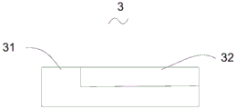
FIG. 4 is a schematic structural view of the semi-cylindrical side block of FIG. 1;
FIG. 5 is a schematic right view of the semi-cylindrical side block of FIG. 4;
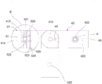
FIG. 6 is a schematic top view of the connection of the dial gauge mounting assembly and the height adjustment assembly of FIG. 1;
FIG. 7 is a schematic view of the structure of the joint shown in FIG. 1;
FIG. 8 is a schematic structural view of the mounting portion shown in FIG. 1;
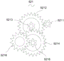
FIG. 9 is a schematic structural view of the first gear assembly shown in FIG. 1;
FIG. 10 is a schematic structural view of the second gear assembly shown in FIG. 1;
FIG. 11 is a schematic view of the construction of the pulling assembly of FIG. 1;
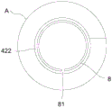
FIG. 12 is a partial enlarged view of area A of FIG. 6;
fig. 13 is a partially enlarged view of the region B shown in fig. 6.
In the drawing, 1, a base, 2, a ribbed working table, 21, ribs, 3, a semi-cylindrical side block, 31, a plane portion, 32, a cylindrical portion, 4, an indicator mounting component, 41, a connecting portion, 411, a slot, 412, a first shaft hole, 413, a first locking hole, 414, a rack channel, 415, a receiving cavity, 42, a mounting portion, 421, a second shaft hole, 422, a mounting through hole, 423, a second locking hole, 43, a rotating shaft, 44, a first locking rod, 45, a second locking rod, 5, a height adjusting component, 51, a rack, 52, a gear control component, 521, a first gear component, 5211, a first gear, 5212, a second gear, 5213, a third gear, 5214, a fourth gear, 5215, a fifth gear, 5216, a sixth gear, 522, a second gear component, 5221, a seventh gear, 5222, an eighth gear, 5223, a ninth gear, 5224, a tenth gear, 523, a first knob, a second knob, 525. the measuring instrument comprises a gear shaft, 526 connecting shafts, 6 lifting assemblies, 61 collars, 62 first pulleys, 63 second pulleys, 64 third pulleys, 65 fourth pulleys, 66 fifth pulleys, 67 pull ropes, 68 pull blocks, 7 indicator, 71 meter bodies, 72 shaft sleeves, 73 measuring rods, 74 measuring heads, 8 protective pieces and 81 notches.
Detailed Description
The technical solutions in the embodiments of the present invention will be clearly and completely described below with reference to the drawings in the embodiments of the present invention, and it is obvious that the described embodiments are only a part of the embodiments of the present invention, and not all of the embodiments. All other embodiments, which can be derived by a person skilled in the art from the embodiments given herein without making any creative effort, shall fall within the protection scope of the present invention.
Fig. 1 shows an indicator verification device in an embodiment of the present invention, which can be used in the verification item of the repeatability of the indicator 7 and the influence of the radial force of the measuring rod 73 on the indicating value, wherein the indicator 7 comprises an indicator type dial indicator or dial indicator, a digital type dial indicator or dial indicator. Fig. 2 shows a pointer type indicating table in the related art, and for the sake of convenience of description of the indicating table verification apparatus of the present invention, in the present invention, an indicating table 7 is described by taking a pointer type indicating table as an example. As shown in fig. 2, the indicating gauge 7 includes a gauge body 71, a sleeve 72, a measuring rod 73, and a measuring head 74, wherein the measuring head 74 is integrally formed with the measuring rod 73, and both are capable of extending and contracting relative to the sleeve 72 when the measuring rod 73 is pulled by an external force or the measuring head 74 is pressed, thereby changing the indication value of the indicating gauge 7.
As shown in fig. 1, the dial gauge calibrating apparatus includes a base 1, a semi-cylindrical side block 3 for contact by a measuring head 74 of a dial gauge 7 to perform calibration, a ribbed table 2 for providing a flat placement area for the semi-cylindrical side block 3, a dial gauge mounting assembly 4, and a height adjusting assembly 5.
The height adjusting component 5 is used for adjusting the height of the indicating meter mounting component 4 relative to the upper surface of the base 1, the height adjusting component 5 comprises a rack 51 and a gear control component 52 meshed with the rack 51, and the rack 51 is arranged on one side of the base 1 at an included angle, so that the heights of different positions of the rack 51 in the length direction relative to the upper surface of the base 1 are different. The gear control assembly 52 is connected with the indicating meter mounting assembly 4, so that the indicating meter mounting assembly 4 is driven to synchronously move by controlling the gear control assembly 52 to move along the length direction of the rack 51, and the height adjustment of the indicating meter mounting assembly 4 is realized.
Wherein, the bottom of the rack 51 can be provided with a mounting column and is mounted on the base 1 through the mounting column. In the present embodiment, the rack 51 is vertically provided on the base 1.
The indicating meter mounting component 4 is used for mounting the indicating meter 7, and the indicating meter mounting component 4 is arranged in parallel with the base 1, so that the indicating meter mounting component 4 is always kept in parallel with the base 1 at different heights. In the present embodiment, the dial gauge mounting assembly 4 includes a connecting portion 41 for connecting with the gear control assembly 52 and a mounting portion 42 for mounting the dial gauge 7. The mounting portion 42 is rotatably connected to the connecting portion 41 so as to rotate relative to the connecting portion 41 along a plane where the dial gauge mounting assembly 4 is located, thereby facilitating adjustment by a verifier according to needs.
As shown in fig. 7 to 8, the connecting portion 41 may be rectangular, and a slot 411 into which the mounting portion 42 is inserted is formed in a side surface of the connecting portion 41, and the mounting portion 42 is rotatably inserted into the slot 411 through a rotating structure and is clamped and fixed by the connecting portion 41. Wherein, revolution mechanic includes first shaft hole 412, second shaft hole 421 and pivot 43, and first shaft hole 412 sets up in the top surface of connecting portion 41 and/or the bottom surface that sets up with the top surface is relative, and runs through slot 411, and second shaft hole 421 runs through the top surface and the bottom surface setting of installation department 42, and pivot 43 wears to locate in first shaft hole 412 and the second shaft hole 421 to rotate the connection of installation department 42 on connecting portion 41.
The first shaft hole 412 and the second shaft hole 421 may be cylindrical, and the rotating shaft 43 may be a cylindrical pin shaft disposed in a manner matching with the first shaft hole 412 and the second shaft hole 421. In the present embodiment, the first shaft hole 412 is provided through the top and bottom surfaces of the connection part. In other embodiments, the connecting portion 41 does not need to be provided with the slot 411, and the mounting portion 42 is rotatably connected to the top surface or the bottom surface of the connecting portion 41 through a rotating structure.
The slot 411 may have a rectangular parallelepiped shape, and the mounting portion 42 may have a substantially rectangular parallelepiped shape, and one end thereof connected to the connecting portion 41 is disposed in an arc shape, as shown in fig. 6, so that the mounting portion 42 can rotate 180 ° or more than 180 ° relative to the connecting portion 41. It can be understood that, when the arc-shaped portion of the mounting portion 42 is inserted into the slot 411 and there is a space between the arc-shaped portion and the bottom of the slot 411 opposite to the opening of the slot, the mounting portion 42 can rotate more than 180 ° with respect to the connecting portion 41; when there is no space between the two, since the side surface of the mounting portion 42 is attached to the bottom of the insertion slot 411 when the mounting portion 42 is rotated 180 ° with respect to the connection portion 41, only 180 ° rotation with respect to the connection portion 41 is possible. It is understood that the adjustment can be made according to the insertion slot 411 and the portion of the mounting portion 42 inserted into the insertion slot 411, so that the rotation of the target angle can be achieved.
The base 1 and the mounting portion 42 are disposed correspondingly, in this embodiment, the size of the base 1 may be greater than or equal to the corresponding area of the mounting portion 42 after the mounting portion 42 rotates within the rotatable range, wherein the base 1 may be disposed in a rectangular parallelepiped shape, or the side of the base 1 near the mounting portion 42 is disposed in an arc shape, and the arc shape may be the same as the rotation track of the mounting portion 42, so that the mounting portion 42 still corresponds to the base 1 after rotating.
In some embodiments, the base 1 may have a size equal to or slightly larger than that of the dial gauge mounting assembly 4, and the base 1 may include a first base corresponding to the connecting portion 41 and a second base corresponding to the mounting portion 42, wherein the second base is rotatably connected to the first base, and a rotation angle of the second base relative to the first base is the same as a rotation angle of the mounting portion 42 relative to the connecting portion 41, so that the mounting portion 42 can still correspond to the base 1 after rotating.
The indicating meter calibrating device further comprises a first locking structure used for locking the mounting portion 42 on the connecting portion 41, the first locking structure comprises a first locking hole 413 and a first locking rod 44, the first locking hole 413 is arranged on at least one of the top surface and the bottom surface of the connecting portion 41 and is communicated with the slot 411, and therefore after the position of the mounting portion 42 is determined, the first locking rod 44 penetrates through the first locking hole 413 and abuts against the mounting portion 42, and therefore the mounting portion 42 is locked.
The first locking hole 413 is located on the side of the connecting portion 41 close to the slot opening of the slot 411, so that the locking effect is good. In this embodiment, the first lock rod 44 may be a screw rod, and a thread adapted to the first lock rod 44 is disposed in the first lock hole 413, so that the first lock rod 44 can be screwed to lock and unlock the mounting portion 42.
The mounting portion 42 is provided with a mounting through hole 422 for mounting the indicator gauge 7, the mounting through hole 422 penetrates the top surface and the bottom surface of the mounting portion 42, and the mounting through hole 422 is provided perpendicular to the upper surface of the base 1. The mounting through hole 422 is formed in a cylindrical shape, and has a diameter larger than the diameter of the boss 72 and smaller than the diameter of the watch body 71, and the thickness of the mounting portion 42 is smaller than the length of the boss 72. It can be understood that when indicating gauge 7 is mounted to mounting portion 42, gauge head 74 and gauge rod 73 of indicating gauge 7 pass through this mounting through-hole 422, the axis of gauge rod 73 is perpendicular to base 1 upper surface, and indicating gauge 7 is spacing-fixed on the top surface of mounting portion 42 through its gauge body 71.
The indicating meter calibrating device further comprises a second locking mechanism used for locking the indicating meter 7 on the mounting portion 42, the second locking mechanism comprises a second locking hole 423 and a second locking rod 45, the second locking hole 423 is arranged on the side face of the mounting portion 42 and communicated with the mounting through hole 422, and the second locking rod 45 penetrates through the second locking hole 423 to abut against the shaft sleeve 72 of the indicating meter 7, so that the indicating meter 7 is locked. In this embodiment, the second lock rod 45 may be a screw rod, a thread adapted to the second lock rod 45 is disposed in the second lock hole 423, and the indicator 7 may be locked and unlocked by screwing the second lock rod 45.
The indicating gauge verifying apparatus further includes a protector 8, as shown in fig. 12, the protector 8 is provided in a cylindrical shape having a diameter greater than that of the boss 72 and slightly smaller than that of the mounting through-hole 422, and the protector 8 is provided with notches 81 penetrating both ends thereof. It is understood that the protection member 8 is configured to be disposed in the mounting through hole 422, and when the indicator gauge 7 is mounted to the mounting portion 42, the collar 72 of the indicator gauge 7 is inserted into the mounting through hole 422 and sleeved thereon by the protection member 8. When the second lock rod 45 is screwed, the second lock rod 45 presses against the protection member 8, and the protection member 8 is deformed through the notch 81 of the protection member so as to wrap the shaft sleeve 72, thereby locking the shaft sleeve 72 and preventing the shaft sleeve 72 from being worn by the second lock rod 45. Wherein, the protection member 8 can be made of copper material.
The second locking hole 423 is perpendicular to the mounting through hole 422, wherein one or more second locking mechanisms may be provided. When one is provided, the second locking mechanism may be located at an intermediate position in the height direction of the mounting portion 42; when provided in plurality, the plurality of second locking mechanisms may be evenly disposed between the top and bottom of the mounting portion 42.
As shown in fig. 1, the gear control assembly 52 is engaged with the rack 51 and is configured to drive the connecting portion 41 to move along the length direction of the rack 51, and the gear control assembly 52 includes a gear mechanism engaged with the rack 51 and a driving mechanism configured to drive the gear mechanism to rotate. Wherein the gear mechanism is arranged in the connecting portion 41.
As shown in fig. 6, the connecting portion 41 is provided with a rack passage 414 through which the rack 51 is inserted and an accommodating chamber 415 for accommodating the gear mechanism, and the rack passage 414 communicates with the accommodating chamber 415. It can be understood that the rack 51 is disposed in the connecting portion 41 through the rack passage 414, and the gear mechanism is disposed in the accommodating cavity 415 through the connecting mechanism, so that the gear mechanism is connected to the connecting portion 41, and the connecting portion 41 is driven to move synchronously by the gear mechanism moving along the length direction of the rack 51.
The gear mechanism may be implemented by one or more gears in meshed connection, it being understood that when the gear mechanism comprises a gear, the parameters of the gear and the rack 51 may be determined by the desired gear and rack transmission relationship, for example, the transmission relationship may be such that when the gear travels one revolution, the gear moves a certain preset distance along the rack 51. When the gear mechanism comprises a plurality of gears, the parameters of the gears and the rack 51 can be determined by the desired transmission relationship between the gears and the rack 51, for example, when the master gear travels one turn, the slave gear connected to the rack 51 moves a predetermined distance along the rack 51. So that the elevation height of the connection part 41 can be controlled by controlling the number of rotations of the main gear.
In the present embodiment, in order to facilitate the height adjustment of the indicator gauge 7 of different ranges, the gear mechanism includes a plurality of gears, and specifically, may include a first gear assembly 521 for adjusting the height by a small amount of movement and a second gear assembly 522 for adjusting the height by a large amount of movement, wherein the first gear assembly 521 and the second gear assembly 522 are disposed at different heights in the length direction of the rack 51 at a spacing distance to prevent mutual interference.
The connecting portion 41 may be a hollow structure, the rack passage 414 is disposed through the top and bottom surfaces of the connecting portion 41 and perpendicular to the upper surface of the base 1, the connecting portion 41 forms an accommodating cavity 415 inside due to its hollow structure, and the gears in the gear assembly are connected to the inner wall of the connecting portion 41 through the gear shaft 525, respectively. It is understood that the connecting mechanism may be a gear shaft 525, and the number of the gear shaft 525 may be arranged corresponding to the number of gears in the first gear assembly 521 and the second gear assembly 522; it can be understood that, when two gears are to be coaxially connected, the two gears are connected together in the connecting portion 41 through a gear shaft 525; when two gears are driven by the meshing connection, the two gears are each connected in the connecting portion 41 by one gear shaft 525.
The driving mechanism may be a knob, and the driving mechanism includes a first knob 523 in transmission connection with the first gear assembly 521 and a second knob 524 in transmission connection with the second gear assembly 522, wherein the first knob 523 and the second knob 524 are disposed outside the connecting portion 41 for rotation, and the first knob 523 and the second knob 524 may be respectively in transmission connection with the first gear assembly 521 and the second gear assembly 522 through corresponding connecting shafts 526. In some embodiments, the first and second knobs 523 and 524 may be connected to the gear shafts 525 on the first and second gear assemblies 521 and 522, respectively, by a connecting shaft 526.
As can be appreciated, by rotating the first knob 523, the first knob 523 drives the connecting shaft 526 and the gear shaft 525 to rotate, and the gear shaft 525 drives the first gear assembly 521 to rotate synchronously; the second knob 524 drives the second gear assembly 522 to rotate synchronously in the same manner.
In some embodiments, the gear shaft 525 may pass through the connection portion 41 and extend out of the connection portion 41 to connect the first and second knobs 523 and 524.
It should be understood that the conventional indicating gauge 7 includes, but is not limited to, ranges of 0-1mm, 0-5mm, and 0-10mm, and in order to facilitate height adjustment of the indicating gauge 7 with different ranges, the following description will take an example that one rotation of the first knob 523 can cause the first gear assembly 521 to drive the connecting portion 41 to adjust the height by a movement amount of approximately 0.6mm, and one rotation of the second knob 524 can drive the connecting portion 41 to adjust the height by an movement amount of approximately 5 mm.
As shown in fig. 1, 6, and 9, the first gear assembly 521 includes a first gear 5211 having a radius of 4mm, a second gear 5212 having a radius of 16mm, a third gear 5213 having a radius of 4mm, a fourth gear 5214 having a radius of 16mm, a fifth gear 5215 having a radius of 4mm, and a sixth gear 5216 having a radius of 10 mm.
The first knob 523 is in transmission connection with the first gear 5211 through the connecting shaft 526 and the gear shaft 525 so as to drive the first gear 5211 to rotate synchronously under the rotation of the first knob 523, the first gear 5211 is in meshing connection with the second gear 5212, the third gear 5213 is coaxially arranged with the second gear 5212, the third gear 5213 is in meshing connection with the fourth gear 5214, the fifth gear 5215 is coaxially arranged with the fourth gear 5214 and is in meshing connection with the sixth gear 5216, and the sixth gear 5216 is in meshing connection with the rack 51. It can be understood that when one rotation of the first knob 523 rotates the first gear 5211 one rotation, the first gear 5211 travels a distance of 25.12mm, and since the transmission multiple of the first gear assembly 521 is 40 times and is a speed reduction transmission, the sixth gear 5216 travels 0.628mm, which is about a movement amount of 0.6mm, and thus drives the mounting portion 42 to ascend and descend by 0.6 mm.
It is understood that, in order to rotate the first knob 523 to rotate the first gear 5211 synchronously, the first knob 523, the connecting shaft 526, the gear shaft 525 and the first gear 5211 may be fixedly connected or integrated, and the gear shaft 525 may rotate in the connecting portion 41, so that the connecting shaft 526, the gear shaft 525 and the first gear 5211 rotate synchronously when the first knob 523 is rotated.
In order to realize transmission between the two gears by meshing connection, the following description will take the example in which the second gear 5212 is rotated by the rotation of the first gear 5211. It can be understood that the gear shaft 525 on the second gear 5212 can be fixedly connected to the connecting portion 41, and the second gear 5212 is arranged on the gear shaft 525 in a penetrating way and can rotate on the gear shaft 525; so that when the first gear 5211 is rotated, the second gear 5212 is rotated. In some embodiments, the second gear 5212 can also be fixedly connected to the gear shaft 525 thereon or be integrally formed with the gear shaft 525, and the gear shaft 525 can rotate in the connecting portion 41; so that when the first gear 5211 is rotated, the second gear 5212 and the gear shaft 525 on the second gear 5212 can be rotated together.
It should be understood that, the transmission relationship in the present embodiment can refer to, but is not limited to, the above-mentioned manner, as long as the knob can drive the corresponding gear to rotate synchronously, and the gears can be connected in a meshing manner to realize transmission, so as to finally realize the lifting adjustment of the connecting portion 41, which is common knowledge in the art and will not be described in detail herein.
As shown in fig. 10, the second gear assembly 522 includes a seventh gear 5221 having a radius of 4mm, an eighth gear 5222 having a radius of 16mm, a ninth gear 5223 having a radius of 8mm, and a tenth gear 5224 having a radius of 10 mm. The second knob 524 is in transmission connection with the seventh gear 5221 through the connecting shaft 526 and the gear shaft 525, so that the seventh gear 5221 is driven to rotate synchronously under the rotation of the second knob 524, the seventh gear 5221 is in meshed connection with the eighth gear 5222, the ninth gear 5223 and the eighth gear 5222 are coaxially arranged and in meshed connection with the tenth gear 5224, and the tenth gear 5224 is in meshed connection with the rack 51. It can be understood that when one rotation of the second knob 524 drives the seventh gear 5221 to rotate one rotation, the seventh gear 5221 moves a distance of 25.12mm, and since the transmission multiple of the second gear assembly 522 is 5 times and is a speed reduction transmission, the tenth gear 5224 moves by 5.024mm, which is about 5mm, and thus drives the mounting portion 42 to move up and down by 5 mm.
The end faces of the first knob 523 and the second knob 524 are provided with scales, and the side face of the connecting portion 41 can also be provided with corresponding scales, so as to distinguish the number of turns of the knob.
The indicating meter calibrating device further comprises a pulling assembly 6 for pulling the measuring rod 73, and as shown in fig. 1 and 11, the pulling assembly 6 comprises a sleeve ring 61, a pulling block 68 and a pulley assembly, wherein the sleeve ring 61 is annularly arranged and is used for being sleeved on the measuring head 74 and/or the measuring rod 73 so as to drive the measuring head 74 and the measuring rod 73 to move. It will be appreciated that the protocol requires the measuring rod 73 to have a diameter of 8mm and the measuring head 74 to have a conical head with a maximum diameter of 8mm, in this embodiment, the inner diameter of the collar 61 is smaller than the diameter of the measuring head 74, wherein the inner diameter of the collar 61 may be 6mm, so that when the collar 61 is fitted on the measuring head 74, the collar 61 is prevented from sliding up to the measuring rod 73 and sliding out upward, and wherein the collar 61 may be made of stainless steel, such as 304 stainless steel.
The pulley assembly comprises a lifting pulley which comprises one or more pulleys, in the embodiment, the lifting pulley comprises a first pulley 62, a second pulley 63 and a third pulley 64, and the 3 pulleys are uniformly arranged in the circumferential direction of the lantern ring 61 and are respectively connected with the lantern ring 61. Wherein, can be equipped with the perforation with the corresponding quantity of pulley quantity on the lantern ring 61, 3 pulleys wear to establish respectively through stay cord 67 and connect on the lantern ring 61. It is understood that the pulling ropes 67 on the 3 pulleys can be collected and extended out, and the pulling block 68 can be connected with the extended pulling ropes 67 to be pulled so as to drive the lantern ring 61 to lift through the 3 pulleys.
In this embodiment, the pulley assembly further includes a drawing pulley, wherein the drawing pulley includes a fourth pulley 65 and a fifth pulley 66, a pulling rope 67 extended from the drawing pulley is wound from the bottom of the fourth pulley 65 and then drawn from the fifth pulley 66, and a pulling block 68 is connected to the end of the finally drawn pulling rope 67. It is understood that the fourth and fifth pulleys 65 and 66 may be located at the same height as the first, second and third pulleys 62, 63 and 64, and the fourth and fifth pulleys 65 and 66 are sequentially disposed away from the pulling pulley, thereby drawing the pulling rope 67 and the pulling block 68 out, preventing interference with the movement of the pulling rope 67 on the pulling pulley; the provision of the fourth pulley 65 and the fifth pulley 66 has an effect of tensioning the rope 67, preventing the rope 67 from being loosened and preventing the pull block 68 from being lifted by its own weight. Wherein, the pull rope 67 can be selected from a cotton rope.
The first pulley 62, the second pulley 63, the third pulley 64, the fourth pulley 65, and the fifth pulley 66 may be disposed on the bottom surface of the mounting portion 42, and the through hole of the collar 61 is disposed corresponding to the mounting through hole 422, so that when the dial gauge 7 is mounted in the mounting through hole 422, the collar 61 may be sleeved on the measuring head 74. Wherein each pulley can be arranged on the mounting portion 42 by means of bonding, screwing, etc.
Wherein, rack 51 sets up perpendicularly on the first side of base 1, and connecting portion 41 is connected and installation department 42 is located the top of base 1 second side with the meshing of rack 51, and accessible control installation department 42 goes up and down to make and form the region that supplies to place ribbed workstation 2 and semicylinder lateral mass 3 between installation department 42 and the second side top of base 1.
Referring to fig. 1 and 3, the ribbed table 2 may be disposed in a cylindrical shape, and one surface of the ribbed table is provided with a plurality of ribs 21 arranged at regular intervals, and end surfaces of the plurality of ribs 21 are located on the same plane to form a plane. This banding workstation 2 supplies to place and provides the plane for semicylinder side block 3 on base 1 and places the region, and the 3 bottom surfaces of semicylinder side block and the protruding muscle 21 place face on the banding workstation 2 carry out line contact to make semicylinder side block 3 keep on a plane, the plane degree is good.
Wherein, the ribbed workbench 2 can be formed on the base 1 in an integrated forming mode, or the ribbed workbench 2 is independently arranged and can be connected on the base 1 through bolts. In some embodiments, the ribbed workbench 2 may have an arc-shaped bar shape, and the shape of the ribbed workbench 2 may be the same as the rotation track of the mounting part 42, so that the ribbed workbench 2 may correspond to the mounting through hole 422; wherein, the ribbed workbench 2 and the base 1 are integrally arranged, or the ribbed workbench 2 is independently arranged.
As shown in fig. 4 and 5, the semi-cylindrical side block 3 includes a planar portion 31 and a cylindrical portion 32, the planar portion 31 and the cylindrical portion 32 are arranged in a length direction of the semi-cylindrical side block 3, wherein the planar portion 31 is square or rectangular, the cylindrical portion 32 is rectangular and has a contour arc at the top, and a highest point of the arc of the cylindrical portion 32 is flush with the top of the planar portion 31, that is, the heights of the planar portion 31 and the cylindrical portion 32 are substantially the same, so that when the same position is verified, the repeatability and the radial force of the measuring rod 73 affect the switching between the two items without adjusting the height.
The repeatability of the indicator gauge calibrating device and the operation method of the measuring rod 73 under the influence of radial stress on the indicating value are illustrated below, wherein the range of the indicator gauge 7 is 0-5mm as an example, and the initial position, the middle position and the final position of the indicator gauge 7 are respectively 0mm, 2.5mm and 5 mm.
The repeatability of the starting position was determined as follows:
s11, rotating the mounting part 42 to a desired position relative to the connecting part 41, and tightening the first lock lever 44 to lock the mounting part 42;
s12, mounting the indicating gauge 7 on the mounting part 42, wherein the measuring head 74 and the measuring rod 73 of the indicating gauge 7 penetrate through the mounting through hole 422, the measuring head 74 of the indicating gauge 7 is sleeved by the lantern ring 61, and the axis of the measuring rod 73 is vertical to the upper surface of the base 1; tightening the second lock lever 45 to lock the boss 72;
s13, placing the ribbed workbench 2 on the base 1, placing the semi-cylindrical side block 3 on the ribbed workbench 2, and enabling the plane part 31 of the semi-cylindrical side block 3 to correspond to the measuring head 74;
s14, rotating the first knob 523 and/or the second knob 524 to adjust the height of the indicating gauge 7 until the measuring head 74 contacts the plane portion 31, at which time the indicating value of the indicating gauge 7 is 0 mm;
s15, the pull blocks 68 are respectively pulled to drive the measuring rod 73 to lift for 5 times, the error of the indication value in the 5 times is recorded, and the difference between the maximum value and the minimum value in the 5 times of the error of the indication value is the indication value repeatability on the initial position.
The calibration steps for the influence of the radial stress on the indication value of the measuring rod 73 at the initial position are as follows:
s21, moving the semi-cylindrical side block 3 to enable the measuring head 74 to be in contact with the position near the highest position of the cambered surface of the cylindrical surface part 32, wherein the indication value of the indication meter 7 is still 0 mm; it is understood that since the highest point of the arc surface of the cylindrical surface portion 32 coincides with the height of the top surface of the planar portion 31, the height of the indicating table 7 does not need to be adjusted;
and S22, moving the semi-cylindrical side block 3 twice respectively at the front, back, left and right 4 positions of the indicating table 7 along the vertical direction of the generatrix of the semi-cylindrical side block 3, recording the position indicating error each time the highest point of the semi-cylindrical side block 3 contacts with the measuring head 74 to generate the maximum value (turning point), and recording the difference between the maximum value and the minimum value in the 8 indicating errors as the influence of the radial stress of the measuring rod 73 on the indicating value.
Therefore, in the initial position, two verification items of repeatability and influence of the radial stress on the indicating value of the measuring rod 73 can be continuously completed, and the height of the indicating gauge 7 does not need to be adjusted when the items are switched.
The repeatability assay procedure for the mesoposition was as follows:
s31, rotating the second knob 524 for half a turn to drive the indicator 7 to descend by 2.5mm approximately, wherein the value of the indicator 7 is near 2.5 mm;
s32 is the same as the step S15.
The calibration steps for the influence of the radial stress on the indication value of the measuring rod 73 at the middle position are as follows:
s41 is the same as the step S21.
S42 is the same as the step S22.
The end position repeatability assay procedure was as follows:
s51, rotating the second knob 524 for half a turn to drive the indicator 7 to descend by 2.5mm approximately, wherein the value of the indicator 7 is near 5 mm;
s52 is the same as the step S15.
The calibration steps for the influence of the radial stress on the indication value of the measuring rod 73 at the tail position are as follows:
s61 is the same as the step S21.
S62 is the same as the step S22.
It is to be understood that the above steps are merely for illustrating the method of using the indicator sheet verification apparatus of the present invention, and are not limited to being performed in the above order during the actual verification operation. The operation method of the calibration items and the use of the related calibration apparatus, in which the repeatability and the radial force of the measuring rod 73 are influenced by the indication value, are well known in the art, and the corresponding description is recorded in the national calibration rules, and will not be described in detail herein.
According to the calibrating device for the indicating meter, the plane part 31 and the cylindrical surface part 32 of the semi-cylindrical side block 3 are equal in height, so that continuous measurement of two calibrating items can be realized at the initial, middle and final height positions of the indicating meter 7, the repeatability and the radial stress of the measuring rod 73 affect the indicating value, and the height is not required to be adjusted to complete another calibrating item after one calibrating item is completely completed, so that half of the height adjusting times are reduced, and the working efficiency is greatly improved; through the knob that is equipped with two kinds of displacement of big, little, can find suitable height fast, accurately when being convenient for single adjustment, change the instruction list 7 position operation swift, accurate. The position of the mounting part 42 is convenient to adjust, and the position of the whole device is not required to be adjusted; the measuring rod 73 is convenient to lift.
It is to be understood that the foregoing examples, while indicating the preferred embodiments of the invention, are given by way of illustration and description, and are not to be construed as limiting the scope of the invention; it should be noted that, for those skilled in the art, the above technical features can be freely combined, and several changes and modifications can be made without departing from the concept of the present invention, which all belong to the protection scope of the present invention; therefore, all equivalent changes and modifications made within the scope of the claims of the present invention should be covered by the claims of the present invention.
Claims (10)
1. The calibrating device for the indicating gauge is suitable for calibrating items of indicating gauge (7) with repeatability and indicating value influence caused by radial stress of a measuring rod (73), and is characterized by comprising a base (1), a semi-cylindrical side block (3) for enabling a measuring head (74) of the indicating gauge (7) to contact for calibration, a ribbed workbench (2) for providing a plane placing area for the semi-cylindrical side block (3), an indicating gauge mounting component (4) for mounting the indicating gauge (7) and a height adjusting component (5) for adjusting the height of the indicating gauge mounting component (4) relative to the upper surface of the base (1);
height adjusting part (5) including be the contained angle set up in rack (51) on base (1) and with gear control assembly (52) that rack (51) meshing is connected, gear control assembly (52) with indicator installation component (4) are connected, are used for driving indicator installation component (4) are followed the length direction of rack (51) removes in order to adjust the height.
2. The apparatus for certification of the indicating sheet as set forth in claim 1, wherein the indicating sheet mounting assembly (4) is disposed in parallel with the base (1);
the indicating meter installation component (4) comprises a connecting portion (41) and an installation portion (42), the connecting portion (41) is used for being connected with the gear control component (52), the installation portion (42) is used for being installed on the indicating meter (7), the installation portion (42) is rotatably connected with the connecting portion (41), and the plane where the indicating meter installation component (4) is located is opposite to the connecting portion (41) in rotation.
3. The verification device for the indicating sheet as claimed in claim 2, wherein a slot (411) for inserting the mounting portion (42) is formed in a side surface of the connecting portion (41), and the mounting portion (42) is rotatably inserted into the slot (411) through a rotating structure;
the rotating structure comprises a first shaft hole (412) which is arranged on the connecting portion (41) and penetrates through the slot (411), a second shaft hole (421) which penetrates through the mounting portion (42), and a rotating shaft (43) which penetrates through the first shaft hole (412) and the second shaft hole (421) and is connected with the connecting portion (41) and the mounting portion (42).
4. The device for calibrating the indicating meter according to claim 3, further comprising a first locking structure for locking the installation part (42) on the connection part (41), wherein the first locking structure comprises a first locking hole (413) arranged on the connection part (41) and communicated with the slot (411) and a first locking rod (44) arranged in the first locking hole (413) and abutted against the installation part (42) to lock the installation part (42).
5. The calibrating device for the indicating gauge according to claim 2, wherein the mounting portion (42) is provided with a mounting through hole (422) for the measuring head (74) and the measuring rod (73) to pass through;
the dial gauge calibrating device is still including being used for with dial gauge (7) locking is in second locking structure on installation department (42), second locking structure including set up in installation department (42) go up and with second lockhole (423) and the wear to locate of installation through-hole (422) intercommunication be used for in second lockhole (423) with dial gauge (7) butt is in order to lock second locking lever (45) of dial gauge (7).
6. The device for calibrating the indicating meter according to claim 2, wherein the gear control assembly (52) comprises a gear mechanism in meshed connection with the rack (51) and a driving mechanism for driving the gear mechanism to rotate;
the connecting part (41) is provided with a rack channel (414) for the rack (51) to penetrate through and an accommodating cavity (415) for accommodating the gear mechanism, and the accommodating cavity (415) is communicated with the rack channel (414); the gear mechanism is arranged in the accommodating cavity (415) through a gear shaft (525), and the control knob is arranged outside the connecting part (41) and is in transmission connection with the gear mechanism.
7. The apparatus for verification of an indicator chart as claimed in claim 6, wherein the gear mechanism comprises a first gear assembly (521) and a second gear assembly (522) respectively engaged with the rack (51) for height adjustment with a small amount of movement; the drive knob comprises a first knob (523) in driving connection with the first gear assembly (521) and a second knob (524) in driving connection with the second gear assembly (522).
8. The calibration device for the indicating gauge according to claim 1, further comprising a pulling assembly (6) for pulling the measuring rod (73), wherein the pulling assembly (6) comprises a sleeve ring (61) which is sleeved on the measuring head (74) and/or the measuring rod (73) to drive the measuring rod (73) and the measuring head (74) to move, a pulling block (68) for pulling, and a pulley assembly which is connected with the pulling block (68) and the sleeve ring (61) and is used for driving the sleeve ring (61) to move along the axial direction of the measuring rod (73) according to the movement of the pulling block (68).
9. The apparatus for verification of an indicator gauge as claimed in claim 1, characterized in that the rack (51) is arranged perpendicular to the base (1).
10. The device for calibrating a dial gauge according to claim 1, wherein the semi-cylindrical side piece (3) comprises a planar portion (31) and a cylindrical portion (32), the highest point of the cylindrical portion (32) being flush with the top of the planar portion (31).
Priority Applications (1)
| Application Number | Priority Date | Filing Date | Title |
|---|---|---|---|
| CN202110968281.XA CN113739834B (en) | 2021-08-23 | 2021-08-23 | Indicating meter calibrating device |
Applications Claiming Priority (1)
| Application Number | Priority Date | Filing Date | Title |
|---|---|---|---|
| CN202110968281.XA CN113739834B (en) | 2021-08-23 | 2021-08-23 | Indicating meter calibrating device |
Publications (2)
| Publication Number | Publication Date |
|---|---|
| CN113739834A true CN113739834A (en) | 2021-12-03 |
| CN113739834B CN113739834B (en) | 2023-07-14 |
Family
ID=78732292
Family Applications (1)
| Application Number | Title | Priority Date | Filing Date |
|---|---|---|---|
| CN202110968281.XA Active CN113739834B (en) | 2021-08-23 | 2021-08-23 | Indicating meter calibrating device |
Country Status (1)
| Country | Link |
|---|---|
| CN (1) | CN113739834B (en) |
Citations (7)
| Publication number | Priority date | Publication date | Assignee | Title |
|---|---|---|---|---|
| GB2110371A (en) * | 1981-08-10 | 1983-06-15 | Mitutoyo Mfg Co Ltd | Height gauge |
| TW200907542A (en) * | 2007-08-09 | 2009-02-16 | Benq Corp | Height adjustment device with fine tuning of an image system |
| CN208235487U (en) * | 2018-04-18 | 2018-12-14 | 广东有色工程勘察设计院 | A kind of monitoring mark for pit retaining monitoring |
| CN208418443U (en) * | 2018-05-15 | 2019-01-22 | 刘烨 | A kind of energy-saving LED road lamp bracket of adjustable up-down |
| CN209783474U (en) * | 2019-06-03 | 2019-12-13 | 上海东培企业有限公司 | Adjustable height measuring device |
| CN210512985U (en) * | 2019-09-05 | 2020-05-12 | 陕西亿联中科智能科技有限公司 | Measuring device is used in heating panel production |
| CN211576232U (en) * | 2020-04-22 | 2020-09-25 | 台州市计量设备技术校准中心 | Standard device of grating type indicating meter calibrating instrument |
-
2021
- 2021-08-23 CN CN202110968281.XA patent/CN113739834B/en active Active
Patent Citations (7)
| Publication number | Priority date | Publication date | Assignee | Title |
|---|---|---|---|---|
| GB2110371A (en) * | 1981-08-10 | 1983-06-15 | Mitutoyo Mfg Co Ltd | Height gauge |
| TW200907542A (en) * | 2007-08-09 | 2009-02-16 | Benq Corp | Height adjustment device with fine tuning of an image system |
| CN208235487U (en) * | 2018-04-18 | 2018-12-14 | 广东有色工程勘察设计院 | A kind of monitoring mark for pit retaining monitoring |
| CN208418443U (en) * | 2018-05-15 | 2019-01-22 | 刘烨 | A kind of energy-saving LED road lamp bracket of adjustable up-down |
| CN209783474U (en) * | 2019-06-03 | 2019-12-13 | 上海东培企业有限公司 | Adjustable height measuring device |
| CN210512985U (en) * | 2019-09-05 | 2020-05-12 | 陕西亿联中科智能科技有限公司 | Measuring device is used in heating panel production |
| CN211576232U (en) * | 2020-04-22 | 2020-09-25 | 台州市计量设备技术校准中心 | Standard device of grating type indicating meter calibrating instrument |
Also Published As
| Publication number | Publication date |
|---|---|
| CN113739834B (en) | 2023-07-14 |
Similar Documents
| Publication | Publication Date | Title |
|---|---|---|
| DE202008002919U1 (en) | Actuator for testing torque wrenches | |
| JP5222557B2 (en) | A micrometer configured with a non-rotating spindle | |
| US7484427B2 (en) | Adjustable torque thread gauge assembly and method of calibration thereof | |
| CN113739834A (en) | Indicator calibrating device | |
| CN207936891U (en) | A kind of instrument for measuring pitch diameter of internal thread | |
| EP0327669B1 (en) | Dial bore gage | |
| US4206548A (en) | Measuring tool for taper bores | |
| CN109029981B (en) | Internal gear double-sided meshing measuring device and measuring method | |
| CN216770438U (en) | Differential gear backlash measuring device | |
| CN214065944U (en) | Angle measuring tool | |
| CN210952596U (en) | Spiral coil pipe size inspection device | |
| US20140360034A1 (en) | Angularity Gage | |
| US3638324A (en) | Gage | |
| US2844877A (en) | Gauge tool | |
| US20090249884A1 (en) | Electrically measuring expansions on cylindrical bodies | |
| KR100422885B1 (en) | Apparatus for checking a tapped hole | |
| CN110132102B (en) | Multifunctional measuring tool and hole measuring method | |
| EP2764342B1 (en) | Device and method for controlling a mounting key | |
| CN201016683Y (en) | Adjustable inner taper gauge | |
| CN218974076U (en) | Connecting device of extensometer calibration instrument | |
| CN110031185A (en) | A kind of detection device and detection method of narrow band filter | |
| DE3630902A1 (en) | Alignment measuring device for the mutual axial positioning of the wheel planes of wheels which are arranged next to one another with parallel axes | |
| CN211373492U (en) | RVDT displacement sensor automatic test platform | |
| CN219151378U (en) | Part roundness correction clamp | |
| DE4421372A1 (en) | Calibration mechanism for use with materials testing machines |
Legal Events
| Date | Code | Title | Description |
|---|---|---|---|
| PB01 | Publication | ||
| PB01 | Publication | ||
| SE01 | Entry into force of request for substantive examination | ||
| SE01 | Entry into force of request for substantive examination | ||
| GR01 | Patent grant | ||
| GR01 | Patent grant |