CN113689981A - High-sealing-performance cable assembly and processing technology thereof - Google Patents

High-sealing-performance cable assembly and processing technology thereof Download PDF

Info

Publication number
CN113689981A
CN113689981A CN202110977156.5A CN202110977156A CN113689981A CN 113689981 A CN113689981 A CN 113689981A CN 202110977156 A CN202110977156 A CN 202110977156A CN 113689981 A CN113689981 A CN 113689981A
Authority
CN
China
Prior art keywords
cable
sub
connector
female
wire
Prior art date
Legal status (The legal status is an assumption and is not a legal conclusion. Google has not performed a legal analysis and makes no representation as to the accuracy of the status listed.)
Granted
Application number
CN202110977156.5A
Other languages
Chinese (zh)
Other versions
CN113689981B (en
Inventor
沈桂林
陈静
Current Assignee (The listed assignees may be inaccurate. Google has not performed a legal analysis and makes no representation or warranty as to the accuracy of the list.)
Yangzhou Jingcheng Electronics Co ltd
Original Assignee
Yangzhou Jingcheng Electronics Co ltd
Priority date (The priority date is an assumption and is not a legal conclusion. Google has not performed a legal analysis and makes no representation as to the accuracy of the date listed.)
Filing date
Publication date
Application filed by Yangzhou Jingcheng Electronics Co ltd filed Critical Yangzhou Jingcheng Electronics Co ltd
Priority to CN202110977156.5A priority Critical patent/CN113689981B/en
Publication of CN113689981A publication Critical patent/CN113689981A/en
Application granted granted Critical
Publication of CN113689981B publication Critical patent/CN113689981B/en
Active legal-status Critical Current
Anticipated expiration legal-status Critical

Links

Images

Classifications

    • HELECTRICITY
    • H01ELECTRIC ELEMENTS
    • H01BCABLES; CONDUCTORS; INSULATORS; SELECTION OF MATERIALS FOR THEIR CONDUCTIVE, INSULATING OR DIELECTRIC PROPERTIES
    • H01B7/00Insulated conductors or cables characterised by their form
    • H01B7/17Protection against damage caused by external factors, e.g. sheaths or armouring
    • H01B7/18Protection against damage caused by wear, mechanical force or pressure; Sheaths; Armouring
    • H01B7/20Metal tubes, e.g. lead sheaths
    • H01B7/207Metal tubes, e.g. lead sheaths composed of iron or steel
    • HELECTRICITY
    • H01ELECTRIC ELEMENTS
    • H01RELECTRICALLY-CONDUCTIVE CONNECTIONS; STRUCTURAL ASSOCIATIONS OF A PLURALITY OF MUTUALLY-INSULATED ELECTRICAL CONNECTING ELEMENTS; COUPLING DEVICES; CURRENT COLLECTORS
    • H01R13/00Details of coupling devices of the kinds covered by groups H01R12/70 or H01R24/00 - H01R33/00
    • H01R13/46Bases; Cases
    • H01R13/52Dustproof, splashproof, drip-proof, waterproof, or flameproof cases
    • H01R13/5205Sealing means between cable and housing, e.g. grommet
    • HELECTRICITY
    • H01ELECTRIC ELEMENTS
    • H01RELECTRICALLY-CONDUCTIVE CONNECTIONS; STRUCTURAL ASSOCIATIONS OF A PLURALITY OF MUTUALLY-INSULATED ELECTRICAL CONNECTING ELEMENTS; COUPLING DEVICES; CURRENT COLLECTORS
    • H01R13/00Details of coupling devices of the kinds covered by groups H01R12/70 or H01R24/00 - H01R33/00
    • H01R13/58Means for relieving strain on wire connection, e.g. cord grip, for avoiding loosening of connections between wires and terminals within a coupling device terminating a cable
    • HELECTRICITY
    • H01ELECTRIC ELEMENTS
    • H01RELECTRICALLY-CONDUCTIVE CONNECTIONS; STRUCTURAL ASSOCIATIONS OF A PLURALITY OF MUTUALLY-INSULATED ELECTRICAL CONNECTING ELEMENTS; COUPLING DEVICES; CURRENT COLLECTORS
    • H01R4/00Electrically-conductive connections between two or more conductive members in direct contact, i.e. touching one another; Means for effecting or maintaining such contact; Electrically-conductive connections having two or more spaced connecting locations for conductors and using contact members penetrating insulation
    • H01R4/70Insulation of connections
    • H01R4/72Insulation of connections using a heat shrinking insulating sleeve
    • HELECTRICITY
    • H01ELECTRIC ELEMENTS
    • H01RELECTRICALLY-CONDUCTIVE CONNECTIONS; STRUCTURAL ASSOCIATIONS OF A PLURALITY OF MUTUALLY-INSULATED ELECTRICAL CONNECTING ELEMENTS; COUPLING DEVICES; CURRENT COLLECTORS
    • H01R43/00Apparatus or processes specially adapted for manufacturing, assembling, maintaining, or repairing of line connectors or current collectors or for joining electric conductors
    • H01R43/04Apparatus or processes specially adapted for manufacturing, assembling, maintaining, or repairing of line connectors or current collectors or for joining electric conductors for forming connections by deformation, e.g. crimping tool
    • H01R43/048Crimping apparatus or processes
    • H01R43/05Crimping apparatus or processes with wire-insulation stripping
    • YGENERAL TAGGING OF NEW TECHNOLOGICAL DEVELOPMENTS; GENERAL TAGGING OF CROSS-SECTIONAL TECHNOLOGIES SPANNING OVER SEVERAL SECTIONS OF THE IPC; TECHNICAL SUBJECTS COVERED BY FORMER USPC CROSS-REFERENCE ART COLLECTIONS [XRACs] AND DIGESTS
    • Y02TECHNOLOGIES OR APPLICATIONS FOR MITIGATION OR ADAPTATION AGAINST CLIMATE CHANGE
    • Y02ATECHNOLOGIES FOR ADAPTATION TO CLIMATE CHANGE
    • Y02A30/00Adapting or protecting infrastructure or their operation
    • Y02A30/14Extreme weather resilient electric power supply systems, e.g. strengthening power lines or underground power cables

Landscapes

  • Engineering & Computer Science (AREA)
  • Manufacturing & Machinery (AREA)
  • Cable Accessories (AREA)
  • Connector Housings Or Holding Contact Members (AREA)

Abstract

本发明公开了高密封性电缆组件及其加工工艺,包括导体线缆,线缆总共分为三层,最内部为线芯,线芯外包裹有钢甲层,钢甲层外包裹有外层护套,并且,线缆的一端通过线芯插接于子端连接器内并通过两个固定螺钉拧紧固定,另一端通过线芯插接于母端连接器内并通过两个固定螺钉拧紧固定,子端连接器的一端设置有子接线口,并在子接线口的内部固定设置子绝缘块,在子绝缘块的上方设置子接线,子绝缘块采用绝缘材料制成,并且该材料不能发生形变,否则固定螺钉无法压紧线芯,其次,在子接线上设置子波纹,在通过固定螺钉进行线芯的压紧时,子波纹可以起到防滑的作用,抗拉扯。

Figure 202110977156

The invention discloses a high-sealing cable assembly and a processing technology thereof, including a conductor cable. The cable is divided into three layers in total, the innermost part is a wire core, the wire core is wrapped with a steel armor layer, and the steel armor layer is wrapped with an outer layer Sheath, and one end of the cable is inserted into the sub-end connector through the wire core and fastened and fixed by two fixing screws, and the other end is inserted into the female end connector through the wire core and fixed by two fixing screws. , one end of the sub-terminal connector is provided with a sub-wiring port, and a sub-insulating block is fixed inside the sub-wiring port, and a sub-wiring is arranged above the sub-insulating block. The sub-insulating block is made of insulating material, and the material cannot produce Otherwise, the fixing screw cannot compress the wire core. Secondly, the sub-corrugation is arranged on the sub-wiring. When the wire core is compressed by the fixing screw, the sub-corrugation can play a non-slip effect and resist pulling.

Figure 202110977156

Description

High-sealing-performance cable assembly and processing technology thereof
Technical Field
The invention relates to the technical field of cable assemblies, in particular to a high-sealing cable assembly and a processing technology thereof.
Background
The cable has at least one conductor surrounded by a shielding layer, in many cases, the cable is provided with components such as a connector and the like to ensure the transmission of energy or information, but in the existing cable components, the connection between the cable components and the connector is mostly spiral binding or welding, in the connection mode, under the condition of a plurality of large tension values, the connection between the connector and the cable is loosened or the welding connection is partially damaged, the use is influenced, in addition, the cable head is the weakest part in the cable components, the installation tightness is the key of safe operation of a cable line, and therefore, the tightness problem of the connection of the cable components is further solved.
Disclosure of Invention
The invention aims to provide a high-tightness cable assembly and a processing technology thereof, and solves the following technical problems:
under the condition of larger tension value, the connection between the connector and the cable becomes loose or the welded connection is partially damaged, so that the use is influenced; the cable head is the weakest part of the cable assembly and the tightness of the installation is a problem.
The purpose of the invention can be realized by the following technical scheme:
high leakproofness cable subassembly, including the cable, its characterized in that, the inside of cable is provided with the sinle silk, the outer parcel of sinle silk is provided with the armor layer, the outer parcel of armor layer is provided with outer sheath, the one end of cable is passed through the sinle silk and is pegged graft in the sub-end connector and fixed through set screw, the other end of cable passes through the sinle silk and pegs graft in the sub-end connector and fixed through set screw.
As a further scheme of the invention: the one end of sub-end connector is provided with sub-wiring mouth, the fixed sub-insulating block that is provided with in inside of sub-wiring mouth, the top of sub-insulating block is provided with sub-wiring, be provided with sub-ripple on the sub-wiring, the one end of sub-wiring is provided with the sub-wire loop, and the middle part of sub-wire loop is provided with the sub-plug.
As a further scheme of the invention: the outer portion of the terminal connector is provided with a connecting external thread, and the outer portion of the terminal connector is provided with a plurality of anti-skidding lugs in an annular array.
As a further scheme of the invention: the one end of female connector is provided with female wiring mouth, the other end of female connector has been seted up to the interface, the fixed female insulating block that is provided with in inside of female wiring mouth, the top of female insulating block is provided with female wiring, be provided with female ripple on the female wiring, the one end of female wiring is provided with the bus ring.
As a further scheme of the invention: the outside of female end connector is the annular array and is provided with a plurality of anti-skidding lugs.
As a further scheme of the invention: female end connector cup joint is provided with solid fixed ring, be provided with sealed the pad between solid fixed ring and the female end connector, gu the inside one end of fixed ring has been seted up and has been connected the internal thread.
As a further scheme of the invention: and a sealing sleeve is sleeved and connected at the connecting part of the cable and the sub-end connector.
As a further scheme of the invention: and a sealing sleeve is sleeved and connected at the connecting part of the cable and the female end connector.
The invention also discloses a processing technology of the high-sealing cable assembly, which comprises the following steps:
the method comprises the following steps: stripping an outer layer of a sheath: selecting a corresponding ring-cutting knife according to the diameter of a steel armor layer in the cable, performing outer-layer ring-cutting on two ends of the cable, and stripping an outer-layer sheath;
step two: stripping a steel shell layer: after the first step is finished, a circle of annular deep marks are sawed by an annular saw around the steel armor layer close to the annular cutting part of the cable, the steel armor layer is pried by a straight screwdriver, then the steel armor layer is torn by a clamp, and finally burrs on the edge of the steel armor layer are polished by a polishing machine;
step three: moisture removing and gluing: baking the cable from the middle part to the two ends of the cable by using a gas spray gun, removing moisture in the cable, and sealing the circular cuts at the two ends of the cable by using hot melt adhesive;
step four: mounting an upper sleeve: the two sealing sleeves are respectively sleeved on the cable, then the wire cores at two ends of the cable are respectively inserted into the sub-end connector and the female end connector, and are respectively compressed and fixed through the fixing screws;
step five: thermal shrinkage sealing: and moving the sealing sleeve sleeved on the cable to the part connected with the fixing screws at the two ends of the wire core, and then drying and spraying the sealing sleeve by a gas spray gun for hot melting.
The invention has the beneficial effects that:
according to the anti-slip connector, the connecting external threads are arranged on the outer portion of the sub-end connector, the anti-slip lugs are arranged on the outer portions of the sub-end connector and the female end connector, during production and machining, the two ends of a cable in each cable assembly are respectively connected with the sub-end connector and the female end connector, after connection is completed, a sealing sleeve needs to be sleeved on each connecting portion, sealing performance and insulating performance of the connecting portions are guaranteed, the sealing sleeve is an insulating heat-shrinkable sleeve and has the performance of shrinking and insulating when heated, the anti-slip lugs can prevent the sealing sleeve from falling off after sealing, and sealing performance is improved.
Secondly, female end connector cup joints outward and sets up solid fixed ring, sets up a sealed pad between solid fixed ring and female end connector, sealed pad adopts insulating rubber to make, when child end connector is connected with female end connector, solid fixed ring on the female end connector can carry out threaded connection with the outside external screw thread of being connected of child end connector through inside connection internal thread, just is connected child end connector and female end connector, and this connected mode is connected stably, and it is convenient to dismantle the change, facilitate promotion.
Drawings
The invention will be further described with reference to the accompanying drawings.
FIG. 1 is a schematic view of the overall structure of the present invention;
FIG. 2 is a schematic view of the connection structure of the cable and the core of the present invention;
FIG. 3 is a cross-sectional structural view of a cable according to the present invention;
FIG. 4 is a schematic cross-sectional view of a terminal connector according to the present invention;
FIG. 5 is a side view of the connector of the invention;
FIG. 6 is a schematic side view of a female connector of the present invention;
FIG. 7 is a schematic cross-sectional view of a female end connector according to the present invention;
FIG. 8 is a schematic view of a female insulation block and a female connection terminal according to the present invention;
figure 9 is a schematic view of the construction of the sealing sleeve according to the invention;
FIG. 10 is a schematic sectional view of the connection structure of a neutron-end connector and a mother-end connector according to the present invention.
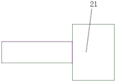
In the figure: 1. a cable; 10. an outer sheath; 11. a steel armor layer; 12. a wire core; 2. a terminal connector; 21. sealing sleeves; 22. a sub-plug; 23. connecting external threads; 24. a sub-wiring port; 25. sub-wiring; 26. sub-corrugations; 27. a sub-wire loop; 28. a sub-insulating block; 3. a female end connector; 30. an anti-slip bump; 31. a set screw; 32. a female insulating block; 33. a gasket; 34. a female wiring port; 35. a female connection wire; 36. female corrugation; 37. a bus ring; 38. a butt joint port; 4. a fixing ring; 41. connecting the internal threads; 42. a connection pad.
Detailed Description
The technical solutions in the embodiments of the present invention will be clearly and completely described below with reference to the drawings in the embodiments of the present invention, and it is obvious that the described embodiments are only a part of the embodiments of the present invention, and not all of the embodiments. All other embodiments, which can be derived by a person skilled in the art from the embodiments given herein without making any creative effort, shall fall within the protection scope of the present invention.
Referring to fig. 1 and 3, the present invention is a high-sealability cable assembly, including a conductor cable 1, the cable 1 is divided into three layers, the innermost portion is a core 12, the core 12 is wrapped with a steel armor layer 11, the steel armor layer 11 is wrapped with an outer sheath 10, one end of the cable 1 is inserted into the sub-end connector 2 through the core 12 and is screwed and fixed by two fixing screws 31, and the other end is inserted into the main-end connector 3 through the core 12 and is screwed and fixed by two fixing screws 31.
Referring to fig. 4 and 5, in design, one end of the sub-terminal connector 2 is provided with a sub-connection port 24, a sub-insulation block 28 is fixedly arranged inside the sub-connection port 24, a sub-connection 25 is arranged above the sub-insulation block 28, the sub-insulation block 28 is made of an insulation material, and the material cannot deform, otherwise, the fixing screw 31 cannot compress the wire core 12, and secondly, a sub-corrugation 26 is arranged on the sub-connection 25, when the wire core 12 is compressed by the fixing screw 31, the sub-corrugation 26 can play a role of skid resistance and tensile resistance, and a sub-wire ring 27 is arranged at one end of the sub-connection 25, and a sub-plug 22 is arranged in the middle of the sub-wire ring 27;
as for the design of the female connector 3, referring to fig. 6, 7 and 8, one end is provided with a female connection port 34, the other end is provided with a butt port 38, like the female connection port 24, a female insulation block 32 is fixedly arranged inside the female connection port 34, a female connection line 35 is arranged above the female insulation block 32, the female insulation block 32 also plays an insulation role, a female ripple 36 is arranged on the female connection line 35 to ensure the stability when the fixing screw 31 is fastened, a female wire ring 37 is arranged at one end of the female connection line 35, when the female connector 2 is butt-jointed with the female connector 3, the female wire ring 37 is butt-jointed with the female wire ring 27, and the female wire ring 37 is sleeved on the female plug 22 to communicate the two cables 1.
Secondly, as shown in fig. 2 and fig. 10, the external connection thread 23 is arranged outside the sub-end connector 2, the anti-skid block 30 is arranged outside the sub-end connector 2 and the sub-end connector 3, the fixing ring 4 is arranged outside the sub-end connector 3 in an sleeved mode, a sealing gasket 33 is arranged between the fixing ring 4 and the sub-end connector 3, the sealing gasket 33 is made of insulating rubber, when the sub-end connector 2 is connected with the sub-end connector 3, the fixing ring 4 on the sub-end connector 3 can be in threaded connection with the external connection thread 23 outside the sub-end connector 2 through the internal connection thread 41, the sub-end connector 2 is connected with the sub-end connector 3, the connection mode is stable, the disassembly and replacement are convenient, and the popularization is facilitated.
Referring to fig. 1 and 9, during production, two ends of the cable 1 in each cable assembly are respectively connected to the sub-end connector 2 and the female end connector 3, after the connection is completed, a sealing sleeve 21 needs to be sleeved outside each connection part to ensure the sealing property and the insulating property of the connection part, and the sealing sleeve 21 is an insulating heat-shrinkable sleeve and has the properties of shrinking and insulating when heated.
The processing technology of the high-tightness cable assembly comprises the following steps:
the method comprises the following steps: stripping the outer layer of the sheath 10: selecting a corresponding ring cutter according to the diameter of a steel armor layer 11 in the cable 1, performing outer-layer ring cutting on two ends of the cable 1, and stripping an outer-layer sheath 10, wherein the closed diameter of the ring cutter is ensured to be the same as the diameter of the steel armor layer 11 during ring cutting, and the ring cutter cannot interact with the steel armor layer 11 during ring cutting;
step two: stripping the steel shell layer 11: after the first step is finished, a circle of annular deep marks are sawn by an annular saw around the steel armor layer 11 and clinging to the annular cutting part of the cable 1, the steel armor layer 11 is pried up by a straight screwdriver, then the steel armor layer 11 is torn by a clamp, and finally burrs on the edge of the steel armor layer 11 are polished by a polishing machine;
step three: moisture removing and gluing: baking the cable 1 from the middle part to the two ends by using a gas spray gun, ensuring that the baking temperature does not exceed 120 ℃ during baking, removing moisture in the cable 1, preventing the outer sheath 10 and the steel armor layer 11 from being stripped to enter the moisture, and influencing the service life of the cable, and sealing the circular cuts at the two ends of the cable 1 by using hot melt adhesive after the moisture removal is finished;
step four: mounting an upper sleeve: the two sealing sleeves 21 are respectively sleeved on the cable 1, then the wire cores 12 at two ends of the cable 1 are respectively inserted into the sub-end connector 2 and the female end connector 3, and are respectively compressed and fixed through the fixing screws 31;
step five: thermal shrinkage sealing: the sealing sleeve 21 sleeved on the cable 1 is moved to the part connected with the fixing screws 31 at the two ends of the wire core 12, one end of the sealing sleeve 21 is sleeved on the anti-skid lug 30 of the sub-end connector 2 or the female end connector 3, the other end of the sealing sleeve is positioned on the fixing screw 31, and then the sealing sleeve 21 is baked and sprayed with hot melt through a gas spray gun.
When one cable assembly is connected with another cable assembly in an installing mode, the female connector 2 of one cable assembly is selected to be connected with the female connector 3 of another cable assembly, and the connecting steps are as follows: firstly, the connecting pad 42 is placed in the butt joint port 38 on the female end connector 3, then the female end connector 3 is aligned with the male end connector 2, the bus ring 37 inside the female end connector 3 is inserted into the sub-bus ring 27 inside the male end connector 2, the male plug 22 is inserted into the bus ring 37, and finally, the fixing ring 4 on the female end connector 3 is rotated, so that the fixing ring 4 and the male end connector 2 are fixedly connected in a threaded manner, namely, the connection and installation are completed.
In the description of the present invention, it is to be understood that the terms "upper", "lower", "left", "right", and the like, indicate orientations or positional relationships based on the orientations or positional relationships shown in the drawings, are only for convenience in describing the present invention and simplifying the description, and do not indicate or imply that the referred device or element must have a specific orientation and a specific orientation configuration and operation, and thus, should not be construed as limiting the present invention. Furthermore, "first" and "second" are used for descriptive purposes only and are not to be construed as indicating or implying relative importance or implicitly indicating the number of technical features indicated. Thus, a feature defined as "first" or "second" may explicitly or implicitly include one or more of that feature. In the description of the present invention, "a plurality" means two or more unless otherwise specified.
In the description of the present invention, it should be noted that, unless otherwise explicitly specified or limited, the terms "mounted," "connected," and the like are to be construed broadly and may be, for example, fixedly connected, detachably connected, or integrally connected; can be mechanically or electrically connected; they may be directly connected or indirectly connected through an intermediate member, or they may be connected through two or more elements. The specific meanings of the above terms in the present invention can be understood in specific cases to those skilled in the art.
While one embodiment of the present invention has been described in detail, the description is only a preferred embodiment of the present invention and should not be taken as limiting the scope of the invention. All equivalent changes and modifications made within the scope of the present invention shall fall within the scope of the present invention.

Claims (9)

1. High leakproofness cable assembly, including cable (1), its characterized in that, the inside of cable (1) is provided with sinle silk (12), sinle silk (12) outer parcel is provided with steel first layer (11), steel first layer (11) outer parcel is provided with outer sheath (10), the one end of cable (1) is passed through sinle silk (12) and is pegged graft in sub-end connector (2) and fixed through set screw (31), the other end of cable (1) is passed through sinle silk (12) and is pegged graft in sub-end connector (3) and fixed through set screw (31).
2. The high-sealability cable assembly according to claim 1, wherein one end of the terminal connector (2) is provided with a terminal connection port (24), a terminal insulation block (28) is fixedly arranged inside the terminal connection port (24), a terminal connection wire (25) is arranged above the terminal insulation block (28), a sub-corrugation (26) is arranged on the terminal connection wire (25), one end of the terminal connection wire (25) is provided with a terminal wire ring (27), and the middle part of the terminal wire ring (27) is provided with a sub-plug (22).
3. The high-sealability cable assembly according to claim 1, wherein the outer portion of the terminal connector (2) is provided with a connecting external thread (23), and the outer portion of the terminal connector (2) is provided with a plurality of anti-slip bumps (30) in an annular array.
4. The high-tightness cable assembly according to claim 1, wherein a female connector port (34) is formed at one end of the female connector (3), a butt joint port (38) is formed at the other end of the female connector (3), a female insulating block (32) is fixedly arranged inside the female connector port (34), a female connector wire (35) is arranged above the female insulating block (32), female corrugations (36) are arranged on the female connector wire (35), and a female wire ring (37) is arranged at one end of the female connector wire (35).
5. The high-hermeticity cable assembly according to claim 1, characterized in that the female connector (3) is externally provided with a plurality of anti-slip projections (30) in an annular array.
6. The high-tightness cable assembly according to claim 1, wherein a fixing ring (4) is sleeved outside the female end connector (3), a sealing gasket (33) is arranged between the fixing ring (4) and the female end connector (3), and a connecting internal thread (41) is formed at one end inside the fixing ring (4).
7. The high-tightness cable assembly according to claim 1, wherein a gland (21) is sleeved outside a connecting portion of the cable (1) and the terminal connector (2).
8. The high-tightness cable assembly according to claim 1, wherein a gland (21) is sleeved at the connecting portion of the cable (1) and the female connector (3).
9. The processing technology of the high-tightness cable assembly is characterized by comprising the following steps of:
the method comprises the following steps: stripping the outer layer jacket (10): selecting a corresponding girdling cutter according to the diameter of a steel armor layer (11) in the cable (1), carrying out outer girdling on two ends of the cable (1) and stripping an outer sheath (10);
step two: stripping the steel armor layer (11): after the first step is finished, a circle of annular deep marks are sawed by an annular saw around the steel armor layer (11) and close to the annular cutting part of the cable (1), the steel armor layer (11) is pried by a straight screwdriver, then the steel armor layer (11) is torn by a pliers, and finally burrs on the edge of the steel armor layer (11) are polished by a polishing machine;
step three: moisture removing and gluing: baking the cable (1) from the middle part to the two ends by using a gas spray gun, removing moisture in the cable (1), and sealing the circular cuts at the two ends of the cable (1) by using hot melt adhesive;
step four: mounting an upper sleeve: the two sealing sleeves (21) are respectively sleeved on the cable (1), then the wire cores (12) at the two ends of the cable (1) are respectively inserted into the sub-end connector (2) and the main-end connector (3) and are respectively compressed and fixed through the fixing screws (31);
step five: thermal shrinkage sealing: the sealing sleeve (21) sleeved on the cable (1) is moved to the part connected with the fixing screws (31) at the two ends of the wire core (12), and then the sealing sleeve (21) is subjected to drying, spraying and hot melting through a gas spray gun.
CN202110977156.5A 2021-08-24 2021-08-24 High-sealing-performance cable assembly and processing technology thereof Active CN113689981B (en)

Priority Applications (1)

Application Number Priority Date Filing Date Title
CN202110977156.5A CN113689981B (en) 2021-08-24 2021-08-24 High-sealing-performance cable assembly and processing technology thereof

Applications Claiming Priority (1)

Application Number Priority Date Filing Date Title
CN202110977156.5A CN113689981B (en) 2021-08-24 2021-08-24 High-sealing-performance cable assembly and processing technology thereof

Publications (2)

Publication Number Publication Date
CN113689981A true CN113689981A (en) 2021-11-23
CN113689981B CN113689981B (en) 2023-03-14

Family

ID=78582246

Family Applications (1)

Application Number Title Priority Date Filing Date
CN202110977156.5A Active CN113689981B (en) 2021-08-24 2021-08-24 High-sealing-performance cable assembly and processing technology thereof

Country Status (1)

Country Link
CN (1) CN113689981B (en)

Cited By (1)

* Cited by examiner, † Cited by third party
Publication number Priority date Publication date Assignee Title
CN114361860A (en) * 2021-12-02 2022-04-15 周严 Electrical wiring terminal

Citations (7)

* Cited by examiner, † Cited by third party
Publication number Priority date Publication date Assignee Title
JP2003004545A (en) * 2001-06-19 2003-01-08 Chubu Sukegawa Kogyo Kk Output deriving device of temperature measuring element
CN102255170A (en) * 2011-04-20 2011-11-23 苏州快可光伏电子股份有限公司 Adapter
CN206364328U (en) * 2017-01-06 2017-07-28 安费诺商用电子产品(成都)有限公司 Field connection water-proof connector
CN207588080U (en) * 2017-11-21 2018-07-06 国网山东省电力公司荣成市供电公司 A kind of power grid cable connecting device
CN210296819U (en) * 2019-10-10 2020-04-10 杭州圣铼电子电器有限公司 Cable with plug-in type multi-joint
CN210607947U (en) * 2019-12-11 2020-05-22 深圳市弘汇通电子科技有限公司 Protection type VGA connecting wire
CN111916948A (en) * 2020-06-24 2020-11-10 杭州赋安能科技有限公司 A kind of new energy vehicle charging plug and its making method

Patent Citations (7)

* Cited by examiner, † Cited by third party
Publication number Priority date Publication date Assignee Title
JP2003004545A (en) * 2001-06-19 2003-01-08 Chubu Sukegawa Kogyo Kk Output deriving device of temperature measuring element
CN102255170A (en) * 2011-04-20 2011-11-23 苏州快可光伏电子股份有限公司 Adapter
CN206364328U (en) * 2017-01-06 2017-07-28 安费诺商用电子产品(成都)有限公司 Field connection water-proof connector
CN207588080U (en) * 2017-11-21 2018-07-06 国网山东省电力公司荣成市供电公司 A kind of power grid cable connecting device
CN210296819U (en) * 2019-10-10 2020-04-10 杭州圣铼电子电器有限公司 Cable with plug-in type multi-joint
CN210607947U (en) * 2019-12-11 2020-05-22 深圳市弘汇通电子科技有限公司 Protection type VGA connecting wire
CN111916948A (en) * 2020-06-24 2020-11-10 杭州赋安能科技有限公司 A kind of new energy vehicle charging plug and its making method

Cited By (1)

* Cited by examiner, † Cited by third party
Publication number Priority date Publication date Assignee Title
CN114361860A (en) * 2021-12-02 2022-04-15 周严 Electrical wiring terminal

Also Published As

Publication number Publication date
CN113689981B (en) 2023-03-14

Similar Documents

Publication Publication Date Title
US8777643B2 (en) Ground strap shield connector
US20150175095A1 (en) Concentric core wire insulating structure and insulating method
US2973501A (en) Flexible electrical connector
CA1286374C (en) Signal cable assembly
CN113612172B (en) Prefabricated electrical quick-install pipeline, connection device and system
US4615114A (en) Method of manufacturing molded buswork for power distribution systems
CN112490700B (en) Two-section type electric connector with multi-strand core wires and connecting method thereof
US4325760A (en) Method of making a cable splice
CN113689981B (en) High-sealing-performance cable assembly and processing technology thereof
CN118571555B (en) A method for preparing a watertight branched optoelectronic composite cable assembly
CN205882178U (en) Power cable connector lug
KR102630244B1 (en) Connection device of distribution line
CN201167228Y (en) Full cold shrinkable cable lug
CN204927539U (en) Electric terminal quick connector
KR100639313B1 (en) Insulation cover for high voltage branch
CN109830332B (en) Intermediate frequency coaxial cable and preparation method thereof
KR100713213B1 (en) High Pressure Cable Connection Safety Tube
CN220209571U (en) Bunched radio frequency cable assembly
CN220190451U (en) Protective sleeve for wiring terminal
CN217009593U (en) Lengthened cable middle head
CN223957275U (en) Be used for whole prefabricated straight joint structure of high tension cable
EP0015128B1 (en) Hose assembly and method of making it
CN222234338U (en) A new type of multi-strand electronic wire harness
CN118825719B (en) High-speed combination cable assemblies
CN220652954U (en) Butt joint device for cable laying

Legal Events

Date Code Title Description
PB01 Publication
PB01 Publication
SE01 Entry into force of request for substantive examination
GR01 Patent grant
GR01 Patent grant
PE01 Entry into force of the registration of the contract for pledge of patent right

Denomination of invention: High sealing cable components and their processing technology

Effective date of registration: 20231229

Granted publication date: 20230314

Pledgee: Agricultural Bank of China Limited Yangzhou Runyang Branch

Pledgor: YANGZHOU JINGCHENG ELECTRONICS CO.,LTD.

Registration number: Y2023980075302

PC01 Cancellation of the registration of the contract for pledge of patent right

Granted publication date: 20230314

Pledgee: Agricultural Bank of China Limited Yangzhou Runyang Branch

Pledgor: YANGZHOU JINGCHENG ELECTRONICS CO.,LTD.

Registration number: Y2023980075302