Disclosure of Invention
Aiming at the problems in the prior art, the invention aims to provide a fluoroplastic coated silicon rubber high-voltage wire and a preparation method thereof, so as to solve the problems that the high-voltage wire generates corona and the sealing performance of crimping of joints at two ends is poor.
In order to achieve the above object, the present invention provides a technical solution as follows:
the utility model provides a fluoroplastics coated silicon rubber high-voltage wire, includes at least one high-voltage wire body, the high-voltage wire body includes conductor, first insulation layer and second insulating layer, the first insulation layer cladding is in the outside of conductor, the first insulation layer is for gathering perfluoroethylene propylene resin extrusion layer, the second insulating layer sets up the first insulation layer outside, the second insulating layer is the silicon rubber coating.
Preferably, the high-voltage wire connector comprises two or more high-voltage wire bodies, a first interface and a second interface are formed on each high-voltage wire body, the first interface is suitable for being sleeved with a conductor of one high-voltage wire body, the second interface is suitable for being sleeved with a conductor of the other high-voltage wire body, threaded holes are formed in the first interface and the second interface respectively, the compression bolt corresponds to the threaded holes, and the compression bolt is suitable for being in threaded connection with the threaded holes to compress the conductors of the high-voltage wire bodies.
Preferably, the anti-dropping device further comprises an anti-dropping piece, a first limiting groove is formed in the high-voltage wire connector, a second limiting groove is formed in the compression bolt, and the anti-dropping piece is suitable for being respectively connected with the first limiting groove and the second limiting groove in an inserting mode so as to limit the compression bolt.
Preferably, the anti-disengaging piece comprises a connecting plate and a first anti-disengaging protrusion, the first anti-disengaging protrusion is arranged on the connecting plate, and the first anti-disengaging protrusion is suitable for being simultaneously connected with the first limiting groove and the second limiting groove in an inserting mode.
Preferably, the first anti-dropping protrusion, the first limiting groove and the second limiting groove are correspondingly provided with two or more groups.
Preferably, the first limiting groove is formed in the inner wall of the threaded hole, and the second limiting groove is formed in the side wall of the compression bolt.
Preferably, the anticreep piece takes off the arch including connecting plate, second anticreep arch and third prevention, the second anticreep protruding with the third prevention take off the arch respectively with connecting plate fixed connection, the second anticreep arch be suitable for with first spacing groove is pegged graft, the third prevention take off the arch be suitable for with the second spacing groove is pegged graft.
Preferably, the second anti-falling bulge and the first limit groove are correspondingly provided with more than two, and/or the third anti-falling bulge and the second limit groove are correspondingly provided with more than two.
Preferably, the first interface and/or the second interface is provided with more than two threaded holes.
The invention also provides a preparation method of the fluoroplastic coated silicon rubber high-voltage wire, which comprises the following steps:
coating a first insulating layer on the surface of a conductor by an extrusion process to obtain an insulating wire, and carrying out plasma treatment on the insulating wire;
immersing the insulated wire into a silicon rubber groove, coating a second insulating layer, and scraping off redundant silicon rubber;
sintering, and cooling to obtain the fluoroplastic coated silicon rubber high-voltage wire.
According to the fluoroplastic coated silicon rubber high-voltage wire and the preparation method thereof provided by the embodiment of the invention, the fluorinated ethylene propylene resin material and the silicon rubber material are combined to form the first insulating layer and the second insulating layer of the conductor, so that good pressure resistance can be ensured, the high-voltage wire has certain elasticity, and the high-voltage wire has good sealing property when a compression joint is installed. The polyfluorinated ethylene propylene resin material has good adhesive force with the lead, and can effectively avoid corona generation. And the mode of combining the fluorinated ethylene propylene resin material and the silicon rubber material can avoid the overlarge outer diameter of the high-voltage wire.
Detailed Description
In order to make the objects, technical solutions and advantages of the present invention more apparent, the present invention will be further described with reference to the accompanying drawings and specific embodiments. It should be understood that the specific embodiments described herein are merely illustrative of the invention and are not intended to limit the invention. All other embodiments, which can be derived by a person skilled in the art from the embodiments given herein without making any creative effort, shall fall within the protection scope of the present invention.
A fluoroplastic-coated silicone high-voltage wire according to an embodiment of the present invention is described below with reference to fig. 1 to 3, where the fluoroplastic-coated silicone high-voltage wire includes at least one high-voltage wire body 100, and the high-voltage wire body 100 includes a conductor 110, a first insulating layer 120, and a second insulating layer 130. The conductor 110 has a concentric stranded circular conductor structure formed by a plurality of conductors of 7, 19, or 37, etc. The first insulating layer 120 is coated outside the conductor 110, the first insulating layer 120 is a perfluoroethylene-propylene copolymer resin extrusion layer, perfluoroethylene-propylene copolymer is extruded by a screw extruder and coated outside the conductor 110 to form the first insulating layer 120. The first insulating layer 120 is made of a relatively hard fluorinated ethylene propylene material, has a good pressure resistance, has a good adhesion force with the conductor 110, and is not prone to corona generation. The second insulating layer 130 is disposed outside the first insulating layer 120, and the second insulating layer 130 is a silicon rubber coating layer. The silicon rubber material used for the second insulating layer 130 has certain flexibility, and can generate elastic deformation when being connected with a crimping connector, so that the sealing performance of a crimping position is ensured. Since the second insulating layer 130 is a coating layer, a sufficient bonding force can be generated between the second insulating layer 130 and the first insulating layer 120, thereby preventing wrinkling.
According to the fluoroplastic coated silicon rubber high-voltage wire provided by the embodiment of the invention, the first insulating layer 120 and the second insulating layer 130 are combined, and the characteristics that the material of the fluorinated ethylene propylene is hard and the material of the silicon rubber has certain flexibility are utilized, so that the fluoroplastic coated silicon rubber high-voltage wire has good sealing property when being connected with a pressure welding joint. Also, an excessive outer diameter of the high-voltage wire can be avoided.
Optionally, the thickness of the first insulating layer 120 is 0.3mm to 0.4mm, and the thickness of the second insulating layer 130 is 0.15 mm.
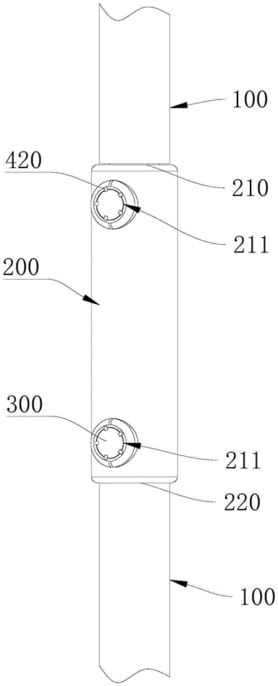
In some embodiments of the present invention, the fluoroplastic coated silicone high voltage wire further includes a high voltage wire connector 200 and a compression bolt 300. The high-voltage wire body 100 is provided with two or more, and the high-voltage wire connector 200 and the hold-down bolt 300 can be used for connecting two adjacent sections of fluoroplastic coated silicon rubber high-voltage wires. It should be noted that the connection of the adjacent fluoroplastic coated silicone high-voltage wires by the high-voltage wire connector 200 or the compression bolt 300 in the embodiment of the present invention is only one alternative of various connection methods.
The high-voltage wire connector 200 is a metal member that can be used for electrical conduction. The high voltage wire connector 200 is formed with a first interface 210 and a second interface 220, wherein the first interface 210 is adapted to be sleeved with the conductor 110 of one of the high voltage wire bodies 100, and the second interface 220 is adapted to be sleeved with the conductor 110 of the other high voltage wire body 100. The first port 210 and the second port 220 are respectively provided with a threaded hole 211, and the axial direction of the threaded hole 211 is perpendicular to the axial direction of the first port 210 and the second port 220. The threaded hole 211 on the first port 210 is communicated with the inner cavity of the first port 210, and the threaded hole 211 on the second port 220 is interlocked with the inner cavity of the second port 220. The pressing bolt 300 is disposed corresponding to the threaded hole 211, and the pressing bolt 300 is adapted to be screwed into the threaded hole 211 to press the conductor 110 of the high voltage wire body 100, so as to connect the high voltage wire connector 200 to the high voltage wire body 100.
Alternatively, the pressing bolt 300 is a torsional shear type bolt, and after the pressing bolt 300 presses the conductor 110, the pressing bolt 300 is sheared when the pressing bolt 300 is continuously rotated, and the portion of the pressing bolt 300 connected to the high-voltage wire connector 200 is separated from the rest.
Alternatively, the high voltage line connector 200 is a tubular structure, and the first interface 210 and the second interface 220 are ends of the high voltage line connector 200, respectively. Usually, the high-voltage line connector 200 is a straight pipe structure, but the high-voltage line connector 200 may be an elbow pipe structure according to the use requirement.
In some embodiments of the present invention, the fluoroplastic coated silicone high voltage wire further includes a release preventing member 400. The high-voltage line connector 200 is provided with a first limiting groove 230, and the hold-down bolt 300 is provided with a second limiting groove 310. The anti-slip member 400 is adapted to be inserted into the first and second limiting grooves 230 and 310, respectively, and is capable of limiting the position of the pressing bolt 300. The anti-release member 400 is installed after the compression bolt 300 is screwed, the anti-release member 400 is simultaneously in plug-in fit with the first limiting groove 230 and the second limiting groove 310, and the anti-release member 400 is a rigid member, so that the compression bolt 300 and the high-voltage wire connector 200 can be fixed in relative positions, and the compression bolt 300 is prevented from loosening.
As shown in fig. 4, in an alternative, the anti-slip member 400 includes a connection plate 410 and a first anti-slip protrusion 420, the first anti-slip protrusion 420 is fixed on the connection plate 410, and the first anti-slip protrusion 420 is adapted to be simultaneously inserted into the first and second limiting grooves 230 and 310. In this case, it is necessary to ensure that the first position-limiting groove 230 is aligned with the second position-limiting groove 310 when the pressing bolt 300 is rotated.
Optionally, two or more sets of the first anti-slip protrusions 420, the first limiting grooves 230 and the second limiting grooves 310 are correspondingly disposed. Each first anti-falling protrusion 420 simultaneously plays a limiting role, so that the stress of the compression bolt 300 is balanced, and the compression bolt is not easy to damage. Moreover, any one of the first limiting grooves 230 may be combined with different second limiting grooves 310, and any one of the first anti-falling protrusions 420 may also be combined with any one of the first limiting grooves 230 and any one of the second limiting grooves 310, so that the flexibility of installation of the hold-down bolt 300 and the anti-falling piece 400 is improved, and the tightness of the hold-down bolt 300 on the wire can be conveniently adjusted.
Alternatively, the first stopper groove 230 is provided on the inner wall of the screw hole 211, and the second stopper groove 310 is provided on the sidewall of the pressing bolt 300. The first stopper groove 230 is opened in both radial and axial directions of the screw hole 211, respectively. The second stopper groove 310 forms an opening in the radial direction of the compression bolt 300 and another opening in the axial direction of the compression bolt 300 (when the compression bolt 300 is a twist-shear type bolt, the opening may be an opening formed in a cross section of the compression bolt 300 after the compression bolt 300 is twist-sheared). When the radial openings of the first and second spacing grooves 230 and 310 are aligned, the first anti-slip protrusions 420 can be inserted into the first and second spacing grooves 230 and 310 at the same time to form spacing.
With reference to fig. 5-7, in another embodiment of the present invention, the anti-separation element 400 includes a connecting plate 410, a second anti-separation protrusion 430 and a third anti-separation protrusion 440, the second anti-separation protrusion 430 and the third anti-separation protrusion 440 are respectively and fixedly connected to the connecting plate 410, the second anti-separation protrusion 430 is adapted to be inserted into the first limiting groove 230, and the third anti-separation protrusion 440 is adapted to be inserted into the second limiting groove 310. The second anti-slip protrusions 430 and the third anti-slip protrusions 440 may be aligned in the radial direction of the connection plate 410, or may be disposed in a staggered manner.
As shown in fig. 6, in an alternative manner, more than two second anti-slip protrusions 430 are provided corresponding to the first limiting grooves 230, and one third anti-slip protrusion 440 is provided corresponding to the second limiting groove 310;
as shown in fig. 7, in another alternative, one second anti-slip projection 430 is provided corresponding to the first limiting groove 230, and more than two third anti-slip projections 440 are provided corresponding to the second limiting groove 310;
as shown in fig. 7, in still another alternative, two or more second anti-slip projections 430 are provided corresponding to the first limiting grooves 230, and two or more third anti-slip projections 440 are provided corresponding to the second limiting grooves 310.
Alternatively, the high voltage line connector 200 and the compression bolt 300 may be provided with at least one corresponding set of score lines, and the relative positions of the first and second retention recesses 230 and 310 may be adapted to receive the release protector 400 when the high voltage line connector 200 is aligned with the score lines on the compression bolt 300, in any of the above configurations of the release protector 400.
In an embodiment of the present invention, at least one of the first interface 210 and the second interface 220 is provided with two or more threaded holes 211, so that the fixing is performed by two or more compression bolts 300, and the fixing firmness is improved.
The embodiment of the invention also provides a preparation method of the fluoroplastic coated silicon rubber high-voltage wire, which comprises the following steps:
s1, coating the first insulating layer 120 on the surface of the conductor 110 by an extrusion process to obtain an insulated wire, and performing plasma treatment on the insulated wire.
The coating process of the first insulating layer 120 can be realized by a screw extruder, and the fluorinated ethylene propylene material of the first insulating layer 120 has better pressure resistance and better adhesion with the conductor 110. The plasma treatment of the insulated wire can activate the surface of the insulated wire, so as to prepare for coating the second insulating layer 130, and improve the bonding effect of the first insulating layer 120 and the second insulating layer 130.
S2, the insulated wire is dipped into a silicone rubber bath to coat the second insulating layer 130, and excess silicone rubber is scraped off.
The silicon rubber groove is filled with a mixture of liquid silicon rubber, color paste and high-temperature glue, and after the insulated wire is immersed in the silicon rubber groove, the mixture of the liquid silicon rubber, the color paste and the high-temperature glue is adhered to the outer wall of the first insulating layer 120 to form a second insulating layer 130. The insulated wire coated with the second insulating layer 130 is passed through a doctor blade to scrape off the excess rubber on the surface. The diameter of the squeegee mold is larger than the diameter of the first insulating layer 120, and the specific size of the squeegee mold can be determined according to the required thickness of the second insulating layer 130, in this embodiment, the diameter of the squeegee mold is 0.2mm larger than the thickness of the first insulating layer 120, i.e. the second insulating layer 130 with the thickness of 0.2mm is scraped.
And S3, sintering and cooling to obtain the fluoroplastic coated silicon rubber high-voltage wire. The insulated wire coated with the second insulating layer 130 is placed in a sintering furnace to be sintered, and the furnace temperature can be controlled to be 150 ℃, 180 ℃, 200 ℃, 250 ℃, 180 ℃ and 130 ℃. And cooling after sintering to obtain the fluoroplastic coated silicon rubber high-voltage wire.
According to the fluoroplastic coated silicone rubber high-voltage wire and the preparation method thereof provided by the embodiment of the invention, the fluorinated ethylene propylene resin material and the silicone rubber material are combined, so that good pressure resistance can be ensured, the high-voltage wire has certain elasticity, and a good sealing property is realized when a compression joint is installed. The polyfluorinated ethylene propylene resin material has good adhesive force with the lead, and can effectively avoid corona generation. And the mode of combining the fluorinated ethylene propylene resin material and the silicon rubber material can avoid the overlarge outer diameter of the high-voltage wire.
In the description of the present invention, it should be noted that the terms "center", "upper", "lower", "left", "right", "vertical", "horizontal", "inner", "outer", "front", "rear", and the like indicate orientations or positional relationships based on those shown in the drawings, and are only for convenience of description and simplicity of description, but do not indicate or imply that the referred device or element must have a specific orientation, be constructed in a specific orientation, and be operated, and thus, should not be construed as limiting the present invention. Furthermore, the terms "first," "second," and "third" are used for descriptive purposes only and are not to be construed as indicating or implying relative importance.
In the description of the present invention, it should be noted that unless otherwise explicitly stated or limited, the terms "mounted," "connected," and "connected" are to be construed broadly and may include, for example, a fixed connection, a detachable connection, an integral connection, a mechanical connection, an electrical connection, a direct connection, an indirect connection via an intermediate medium, and a communication between two elements. The specific meanings of the above terms in the present invention can be understood in specific cases to those skilled in the art. The embodiments and features of the embodiments of the present invention may be combined with each other without conflict.
The above-mentioned embodiments only express the embodiments of the present invention, and the description thereof is more specific and detailed, but not construed as limiting the scope of the present invention. It should be noted that, for a person skilled in the art, several variations and modifications can be made without departing from the inventive concept, which falls within the scope of the present invention. Therefore, the protection scope of the present patent shall be subject to the appended claims.