CN113687594A - Portable nail cover electronic clock - Google Patents
Portable nail cover electronic clock Download PDFInfo
- Publication number
- CN113687594A CN113687594A CN202110903628.2A CN202110903628A CN113687594A CN 113687594 A CN113687594 A CN 113687594A CN 202110903628 A CN202110903628 A CN 202110903628A CN 113687594 A CN113687594 A CN 113687594A
- Authority
- CN
- China
- Prior art keywords
- button
- cover
- electronic clock
- bin
- precession
- Prior art date
- Legal status (The legal status is an assumption and is not a legal conclusion. Google has not performed a legal analysis and makes no representation as to the accuracy of the status listed.)
- Withdrawn
Links
- 238000003780 insertion Methods 0.000 claims abstract description 18
- 230000037431 insertion Effects 0.000 claims abstract description 18
- 239000004973 liquid crystal related substance Substances 0.000 claims abstract description 16
- 210000000282 nail Anatomy 0.000 claims description 41
- 210000003811 finger Anatomy 0.000 claims description 34
- 238000009434 installation Methods 0.000 claims description 12
- 238000001126 phototherapy Methods 0.000 claims description 9
- 238000007789 sealing Methods 0.000 claims description 8
- 239000003292 glue Substances 0.000 claims description 6
- 239000000463 material Substances 0.000 claims description 6
- 239000004033 plastic Substances 0.000 claims description 6
- 210000004905 finger nail Anatomy 0.000 claims description 4
- 210000003813 thumb Anatomy 0.000 claims description 4
- 239000007769 metal material Substances 0.000 claims 1
- 230000003678 scratch resistant effect Effects 0.000 claims 1
- 238000007790 scraping Methods 0.000 abstract description 2
- 239000012790 adhesive layer Substances 0.000 description 3
- 239000002184 metal Substances 0.000 description 3
- 210000005224 forefinger Anatomy 0.000 description 2
- 210000004247 hand Anatomy 0.000 description 2
- 239000010926 waste battery Substances 0.000 description 2
- XLYOFNOQVPJJNP-UHFFFAOYSA-N water Substances O XLYOFNOQVPJJNP-UHFFFAOYSA-N 0.000 description 2
- 230000009286 beneficial effect Effects 0.000 description 1
- 238000012790 confirmation Methods 0.000 description 1
- 239000010410 layer Substances 0.000 description 1
- 238000000034 method Methods 0.000 description 1
- 238000000926 separation method Methods 0.000 description 1
Images


Classifications
-
- G—PHYSICS
- G04—HOROLOGY
- G04G—ELECTRONIC TIME-PIECES
- G04G17/00—Structural details; Housings
- G04G17/08—Housings
-
- G—PHYSICS
- G04—HOROLOGY
- G04G—ELECTRONIC TIME-PIECES
- G04G17/00—Structural details; Housings
-
- G—PHYSICS
- G04—HOROLOGY
- G04G—ELECTRONIC TIME-PIECES
- G04G17/00—Structural details; Housings
- G04G17/02—Component assemblies
- G04G17/04—Mounting of electronic components
- G04G17/045—Mounting of the display
-
- G—PHYSICS
- G04—HOROLOGY
- G04G—ELECTRONIC TIME-PIECES
- G04G19/00—Electric power supply circuits specially adapted for use in electronic time-pieces
-
- G—PHYSICS
- G04—HOROLOGY
- G04G—ELECTRONIC TIME-PIECES
- G04G21/00—Input or output devices integrated in time-pieces
- G04G21/08—Touch switches specially adapted for time-pieces
-
- G—PHYSICS
- G04—HOROLOGY
- G04G—ELECTRONIC TIME-PIECES
- G04G9/00—Visual time or date indication means
- G04G9/08—Visual time or date indication means by building-up characters using a combination of indicating elements, e.g. by using multiplexing techniques
- G04G9/12—Visual time or date indication means by building-up characters using a combination of indicating elements, e.g. by using multiplexing techniques using light valves, e.g. liquid crystals
Landscapes
- Physics & Mathematics (AREA)
- General Physics & Mathematics (AREA)
- Engineering & Computer Science (AREA)
- Power Engineering (AREA)
- Chemical & Material Sciences (AREA)
- Crystallography & Structural Chemistry (AREA)
- Electric Clocks (AREA)
Abstract
The invention discloses a portable electronic clock with a nail cover, which belongs to the technical field of intelligent wearing and comprises an electronic clock box 10, wherein the top surface of the electronic clock box 10 is fixedly connected with an LCD (liquid crystal display) 11, the LCD 11 is fixedly connected with a transparent cover 12, a control panel 13 is arranged inside the electronic clock box 10, one side of the electronic clock box 10 is provided with an anti-scraping arc surface 14, the other side of the electronic clock box 10 is provided with a key cabin 15, the key cabin 15 is provided with a battery transverse insertion cabin 16, the battery transverse insertion cabin 16 is provided with a finger pinching groove 18, a uniformly distributed button electron 17 is arranged in the battery transverse insertion cabin 16, and the bottom surface of the key cabin 15 is provided with three uniformly distributed functional buttons 19. The portable electronic clock with the nail cover is mainly used for solving the problems that the traditional clock is large in size and easy to forget to carry.
Description
Technical Field
The invention relates to a portable nail cover electronic clock, in particular to a portable nail cover electronic clock, and belongs to the technical field of intelligent wearing.
Background
People hold real time in life is a very important thing, and the existing articles which can watch time mainly comprise clocks, mobile phones and the like, but the articles need to be worn on the person, and the time cannot be watched once the articles are not worn on the person.
Based on the above, a time clock which can be worn in real time is needed in the market, the clock is small in size and is integrated with a human body, and therefore, the inventor needs to provide innovation through repeated conception and design.
Disclosure of Invention
The invention mainly aims to provide a portable nail cover electronic clock for solving the problems that the traditional clock is large in size and easy to forget to carry.
The purpose of the invention can be achieved by adopting the following technical scheme: including electronic clock box 10, the top surface fixedly connected with LCD liquid crystal display 11 of electronic clock box 10, fixedly connected with transparent cover 12 on LCD liquid crystal display 11, the inside of electronic clock box 10 is provided with control panel 13, one side of electronic clock box 10 is provided with prevents scraping and bumps cambered surface 14, the opposite side of electronic clock box 10 is provided with button storehouse 15, be provided with the battery on the button storehouse 15 and violently insert storehouse 16, the battery is violently inserted and is provided with finger on the storehouse 16 and hold between the fingers groove 18, the battery is violently inserted and is provided with an evenly distributed button electron 17 in the storehouse 16, the bottom surface of button storehouse 15 is provided with three evenly distributed's function button 19, swing joint has rubber connecting strip 20 on the button storehouse 15, the other end fixedly connected with storehouse lid 21 of rubber connecting strip 20, the inboard edge fixedly connected with rubber seal 22 of storehouse lid 21, a finger button slot 23 is formed in one end of the outer side of the bin cover 21, and a fluorescent key 24 is arranged on one side of the electronic clock box 10; a supporting column 38 is fixedly connected to the bottom surface of the electronic clock box 10, a rotating shaft 39 is arranged on the bottom surface of the supporting column 38, two evenly distributed precession sheets 40 are arranged on the outer side of the supporting column 38, and a buckle 41 is arranged on the top surface of each precession sheet 40; the below of pivot 39 is provided with nail piece 30, the bottom surface of nail piece 30 is provided with phototherapy glue film 31, the top surface fixedly connected with installation base 32 of nail piece 30, be provided with swivelling chute 33 and pivot groove 34 on the installation base 32 respectively, be provided with two evenly distributed's precession lid 35 on the swivelling chute 33, the below of precession lid 35 is provided with precession storehouse 36, the top surface of precession lid 35 is provided with buckle groove 37.
Preferably, the control panel 13 is electrically connected to the LCD 11, the button electronics 17, the function button 19, and the fluorescence button 24, respectively.
Preferably, electrode plates are arranged in the battery transverse insertion bin 16 and are electrically connected with the button electronics 17.
Preferably, the finger grip grooves 18 are formed in the upper and lower portions, and are ergonomically fit for the index finger and thumb.
Preferably, the function keys 19 mainly include a multi-function ok button, an up-multi-function button, and a down-multi-function button.
Preferably, the bin cover 21 and the rubber sealing ring 22 are used in cooperation with the key bin 15.
Preferably, the rotating shaft 39 is used in cooperation with the rotating shaft groove 34, the precession piece 40 is respectively used in cooperation with the rotating groove 33 and the precession bin 36, and the buckle 41 is used in cooperation with the buckle groove 37; the supporting column 38, the rotating shaft 39, the screwing sheet 40 and the buckle 41 are designed in an integrated manner and are made of metal; the installation base 32 and the screw-in cover 35 are designed in an integrated manner, and are made of tough plastic materials.
Preferably, the button electronics 17 are of a mini size, such as model LS 21.
Preferably, the LCD 11 is provided with time, date and other functional designs.
Compared with the prior art, the invention has the beneficial effects that:
1) the electronic clock box 10 designed by the invention is movably connected with the nail plate 30 through the screwing-in sheet 40, so that the electronic clock box 10 can be repeatedly used, and can be attached to the finger cover of a human body through the phototherapy adhesive layer 31 on the nail plate 30, so that a person has no obvious wearing feeling; when people need to watch time, only the LCD liquid crystal display screen 11 on the finger cover needs to be watched, so that the watching time is more convenient.
2) The fluorescent key 24 designed by the invention is matched with the LCD (liquid crystal display) 11 for use, when the light is insufficient, the fluorescent key 24 is pressed, and the LCD 11 is lightened, so that a user can conveniently observe the time; the designed scratch-proof cambered surface 14 can be fused with fingers when the fingers contact objects, so that the operation of daily life is still flexible.
3) The key bin 15 designed by the invention can be hermetically covered by the bin cover 21 to protect electronic elements in the key bin, and even if people frequently wash hands to contact a water source in daily life, the rubber sealing ring 22 can completely isolate the interior from the outside, so that the whole key bin can be more waterproof effectively; when various parameters of the clock need to be adjusted, a user can open the bin cover 21 by buckling the finger buckle open slot 23 with a hand, and can press the function key 19 to adjust the parameters or replace the battery.
4) The mini button battery is adopted in the power supply mode designed by the invention, so that the whole size is smaller, the weight is lighter, and a user can not feel wearing feeling. When the battery is replaced, only the bin cover 21 needs to be opened at each time, the waste battery can be taken out by putting fingers at the position where the fingers hold the groove 18, and then the new battery is plugged into the battery transverse insertion bin 16 to be installed.
5) The electronic clock box 10 is connected with the fingernail sheet 30 in a precession mode, and when the fixed connection is needed, the precession sheet 40 is placed in the position of the rotating groove 33 and then the electronic clock box 10 is rotated, so that the precession sheet 40 enters the precession bin 36 and the buckle 41 is clamped on the buckle groove 37; when disassembly is required, the installation base 32 and the screwing cover 35 are made of plastic materials with toughness, the buckle 41 can be separated from the buckle groove 37 by rotating the electronic clock box 10 with reverse force, and then the electronic clock box 10 is taken down.
Drawings
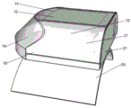
FIG. 1 is a perspective view of the overall structure of a preferred embodiment of the portable electronic timepiece with nail covers according to the present invention;
FIG. 2 is a perspective view of the overall structure of a preferred embodiment of the portable electronic timepiece with fingernails and covers in accordance with the invention;
FIG. 3 is a perspective view of a preferred embodiment of the portable electronic clock with nail covers according to the present invention with the cover open;
FIG. 4 is a perspective view of a preferred embodiment of the portable electronic timepiece with a nail cover according to the invention as a mounting base;
fig. 5 is a perspective view of a preferred embodiment of the portable electronic clock with nail covers according to the present invention as a screw-in plate.
In the figure: 10. an electronic clock box; 11. an LCD liquid crystal display screen; 12. a transparent cover; 13. a control panel; 14. the arc surface is prevented from being scraped and touched; 15. a key bin; 16. the battery is transversely inserted into the bin; 17. the button is electronic; 18. pinching the groove by fingers; 19. function keys; 20. a rubber connecting strip; 21. a bin cover; 22. a rubber seal ring; 23. slotting the finger fasteners; 24. a fluorescent key; 30. a nail plate; 31. a phototherapy adhesive layer; 32. installing a base; 33. a rotating tank; 34. a rotating shaft groove; 35. screwing in the cover; 36. spirally entering a bin; 37. a fastening groove; 38. a support pillar; 39. a rotating shaft; 40. Feeding the sheet in a rotating manner; 41. and (5) buckling.
Detailed Description
In order to make the technical solutions of the present invention more clear and definite for those skilled in the art, the present invention is further described in detail below with reference to the examples and the accompanying drawings, but the embodiments of the present invention are not limited thereto.
As shown in fig. 1-5, the electronic clock box 10 of the portable nail cover electronic clock design provided by the present embodiment is movably connected to the nail plate 30 through the screwing sheet 40, so that the electronic clock box 10 can be repeatedly used, and the phototherapy adhesive layer 31 on the nail plate 30 can be attached to the finger cover of a human body, so that a person has no obvious wearing feeling; when people need to watch time, only the LCD liquid crystal display screen 11 on the finger cover needs to be watched, and even if the fluorescence key 24 is pressed at night, the LCD liquid crystal display screen 11 can be lightened, so that the watching time is more convenient. The electronic clock comprises an electronic clock box 10, an LCD liquid crystal display 11 is fixedly connected to the top surface of the electronic clock box 10, a transparent cover 12 is fixedly connected to the LCD liquid crystal display 11, a control panel 13 is arranged inside the electronic clock box 10, a scratch-proof arc surface 14 is arranged on one side of the electronic clock box 10, a key cabin 15 is arranged on the other side of the electronic clock box 10, a battery transverse insertion cabin 16 is arranged on the key cabin 15, a finger pinching groove 18 is arranged on the battery transverse insertion cabin 16, a plurality of button electrons 17 which are uniformly distributed are arranged in the battery transverse insertion cabin 16, a plurality of function buttons 19 which are uniformly distributed are arranged on the bottom surface of the key cabin 15, a rubber connecting strip 20 is movably connected to the key cabin 15, a cabin cover 21 is fixedly connected to the other end of the rubber connecting strip 20, a rubber sealing ring 22 is fixedly connected to the inner side edge of the cabin cover 21, a finger notching 23 is arranged at one end of the outer side of the cabin cover 21, one side of the electronic clock box 10 is provided with a fluorescent key 24; the bottom surface of the electronic clock box 10 is fixedly connected with a supporting column 38, the bottom surface of the supporting column 38 is provided with a rotating shaft 39, two evenly distributed precession sheets 40 are arranged on the outer side of the supporting column 38, and the top surfaces of the precession sheets 40 are provided with buckles 41; the below of pivot 39 is provided with nail piece 30, and the bottom surface of nail piece 30 is provided with phototherapy glue film 31, and the top surface fixedly connected with installation base 32 of nail piece 30 is provided with swivelling chute 33 and pivot groove 34 on the installation base 32 respectively, is provided with two evenly distributed's precession lid 35 on the swivelling chute 33, and the below of precession lid 35 is provided with precession storehouse 36, and the top surface of precession lid 35 is provided with buckle groove 37.
The control panel 13 is electrically connected with an LCD (liquid crystal display) 11, a button electronic 17, a function button 19 and a fluorescence button 24 respectively. Electrode plates are arranged in the battery transverse insertion bin 16 and are electrically connected with button electronics 17. The finger pinching grooves 18 are arranged at the upper part and the lower part, and both conform to the ergonomics of the forefinger and the thumb. The function keys 19 mainly include a multi-function ok button, an up-multi-function button, and a down-multi-function button. The bin cover 21 and the rubber sealing ring 22 are matched with the key bin 15 for use. The rotating shaft 39 is matched with the rotating shaft groove 34 for use, the precession sheet 40 is respectively matched with the rotating groove 33 and the precession bin 36 for use, and the buckle 41 is matched with the buckle groove 37 for use; the supporting column 38, the rotating shaft 39, the screwing sheet 40 and the buckle 41 are designed into a whole and made of metal; the mounting base 32 and the screw-in cap 35 are designed as one piece and are made of a tough plastic material. The button electronics 17 are of a mini size model, such as model LS 21. The LCD 11 is provided with time, date and other functional designs.
In this embodiment, as shown in fig. 1, the fluorescent key 24 designed by the present invention is used in cooperation with the LCD liquid crystal display 11, when the light is insufficient, the fluorescent key 24 is pressed, and the LCD liquid crystal display 11 is lighted up, so that the user can conveniently observe the time; the designed scratch-proof cambered surface 14 can be fused with fingers when the fingers contact objects, so that the operation of daily life is still flexible. Specifically, one side of the electronic clock box 10 is provided with a fluorescent key 24, and the other side of the electronic clock box 10 is provided with an anti-scratch cambered surface 14.
In this embodiment, as shown in fig. 3, the key top 15 designed by the present invention can be covered with a top cover 21 to protect the electronic components inside, even if people often wash their hands to contact water sources in daily life, the rubber sealing ring 22 can completely isolate the inside from the outside, so that the whole body can be more waterproof; when various parameters of the clock need to be adjusted, a user can open the bin cover 21 by buckling the finger buckle open slot 23 with a hand, and presses the function key 19 to adjust the parameters or replace the battery. Specifically, the bottom surface of the key bin 15 is provided with three evenly distributed function keys 19, the key bin 15 is movably connected with a rubber connecting strip 20, the other end of the rubber connecting strip 20 is fixedly connected with a bin cover 21, the inner side edge of the bin cover 21 is fixedly connected with a rubber sealing ring 22, and the outer side end of the bin cover 21 is provided with a finger buckle slot 23. The function keys 19 mainly include a multi-function confirmation button, an up-adjustment multi-function button, and a down-adjustment multi-function button; the bin cover 21 and the rubber sealing ring 22 are matched with the key bin 15 for use.
In this embodiment, as shown in fig. 3, the power supply mode designed by the present invention employs a mini button battery, so that the overall size is smaller, the weight is lighter, and the user can feel less wearing feeling. When the battery is replaced, only the bin cover 21 needs to be opened at each time, the waste battery can be taken out by putting fingers at the position where the fingers hold the groove 18, and then the new battery is plugged into the battery transverse insertion bin 16 to be installed. Specifically, a key cabin 15 is arranged on the other side of the electronic clock box 10, a battery transverse insertion cabin 16 is arranged on the key cabin 15, a finger pinching groove 18 is arranged on the battery transverse insertion cabin 16, button electrons 17 which are uniformly distributed are arranged in the battery transverse insertion cabin 16, and electrode plates are arranged in the battery transverse insertion cabin 16 and are electrically connected with the button electrons 17; the upper part and the lower part of the finger pinching groove 18 are in accordance with the ergonomics of the forefinger and the thumb; the button electronics 17 are of a mini size model, such as model LS 21.
In this embodiment, as shown in fig. 4 and 5, the electronic clock box 10 is connected to the nail plate 30 by a precession manner, and when a fixed connection is required, the precession piece 40 is placed in the position of the rotation slot 33 and then the electronic clock box 10 is rotated, so that the precession piece 40 enters the precession bin 36 and the buckle 41 is locked on the buckle slot 37; when disassembly is required, the installation base 32 and the screwing cover 35 are made of plastic materials with toughness, the buckle 41 can be separated from the buckle groove 37 by rotating the electronic clock box 10 with reverse force, and then the electronic clock box 10 is taken down. Specifically, a support column 38 is fixedly connected to the bottom surface of the electronic clock box 10, a rotating shaft 39 is arranged on the bottom surface of the support column 38, two evenly distributed precession pieces 40 are arranged on the outer side of the support column 38, and a buckle 41 is arranged on the top surface of each precession piece 40; the below of pivot 39 is provided with nail piece 30, and the bottom surface of nail piece 30 is provided with phototherapy glue film 31, and the top surface fixedly connected with installation base 32 of nail piece 30 is provided with swivelling chute 33 and pivot groove 34 on the installation base 32 respectively, is provided with two evenly distributed's precession lid 35 on the swivelling chute 33, and the below of precession lid 35 is provided with precession storehouse 36, and the top surface of precession lid 35 is provided with buckle groove 37. The rotating shaft 39 is matched with the rotating shaft groove 34 for use, the precession sheet 40 is respectively matched with the rotating groove 33 and the precession bin 36 for use, and the buckle 41 is matched with the buckle groove 37 for use; the supporting column 38, the rotating shaft 39, the screwing sheet 40 and the buckle 41 are designed into a whole and made of metal; the mounting base 32 and the screw-in cap 35 are designed as one piece and are made of a tough plastic material.
In the present embodiment, as shown in fig. 1 to 5, the operation process of the portable electronic clock with a nail cover provided by the present embodiment is as follows:
step 1: the finger button slot 23 is opened by a finger, the bin cover 21 is opened and the button electron 17 is loaded, then the functional key 19 is pressed to adjust various parameters, and the bin cover 21 is closed.
Step 2: the phototherapy glue is smeared on the bottom surface of the nail sheet 30 to form a phototherapy glue layer 31 which is then attached on the nail cover.
And step 3: the electronic clock box 10 is connected with the fingernail piece 30, the precession piece 40 is placed in the position of the rotating groove 33, then the electronic clock box 10 is rotated, so that the precession piece 40 enters the precession bin 36 and the buckle 41 is clamped on the buckle groove 37, and the wearing is finished.
And 4, step 4: the electronic clock box 10 is separated from the nail plate 30, the buckle 41 can be separated from the buckle groove 37 by rotating the electronic clock box 10 with reverse force, then the electronic clock box 10 is taken down, and the nail plate 30 on the finger cover can be taken off by adopting a conventional separation method.
In summary, in the present embodiment, the portable nail cover electronic clock according to the present embodiment.
The above description is only for the purpose of illustrating the present invention and is not intended to limit the scope of the present invention, and any person skilled in the art can substitute or change the technical solution of the present invention and its conception within the scope of the present invention.
Claims (9)
1. A portable nail cover electronic clock comprises an electronic clock box (10) and is characterized in that an LCD (liquid crystal display) screen (11) is fixedly connected to the top surface of the electronic clock box (10), a transparent cover (12) is fixedly connected to the LCD screen (11), a control panel (13) is arranged inside the electronic clock box (10), a scratch-resistant arc surface (14) is arranged on one side of the electronic clock box (10), a button bin (15) is arranged on the other side of the electronic clock box (10), a battery transverse insertion bin (16) is arranged on the button bin (15), a finger pinching groove (18) is arranged on the battery transverse insertion bin (16), a plurality of uniformly distributed button electrons (17) are arranged in the battery transverse insertion bin (16), and a plurality of uniformly distributed function buttons (19) are arranged on the bottom surface of the button bin (15), the key bin (15) is movably connected with a rubber connecting strip (20), the other end of the rubber connecting strip (20) is fixedly connected with a bin cover (21), the edge of the inner side of the bin cover (21) is fixedly connected with a rubber sealing ring (22), one end of the outer side of the bin cover (21) is provided with a finger button slot (23), and one side of the electronic clock box (10) is provided with a fluorescent key (24); a supporting column (38) is fixedly connected to the bottom surface of the electronic clock box (10), a rotating shaft (39) is arranged on the bottom surface of the supporting column (38), two evenly-distributed spiral feeding sheets (40) are arranged on the outer side of the supporting column (38), and buckles (41) are arranged on the top surfaces of the spiral feeding sheets (40); the below of pivot (39) is provided with nail piece (30), the bottom surface of nail piece (30) is provided with phototherapy glue film (31), the top surface fixedly connected with installation base (32) of nail piece (30), be provided with swivelling chute (33) and pivot groove (34) on installation base (32) respectively, be provided with two evenly distributed's precession lid (35) on swivelling chute (33), the below of precession lid (35) is provided with precession storehouse (36), the top surface of precession lid (35) is provided with buckle groove (37).
2. The portable electronic nail cover clock according to claim 1, wherein the control panel (13) is electrically connected to the LCD liquid crystal display (11), the button electronics (17), the function button (19) and the fluorescence button (24), respectively.
3. The portable electronic nail cover clock as claimed in claim 1, wherein the battery cross insertion chamber (16) is provided with electrode plates and is electrically connected with the button electronics (17).
4. The portable electronic fingernail cover clock as defined in claim 1, wherein the finger grip groove (18) is formed in upper and lower portions, both of which conform to ergonomics of the index finger and thumb.
5. A portable electronic nail cover clock according to claim 1, wherein said function buttons (19) mainly comprise a multi-function ok button, a up-multi-function button and a down-multi-function button.
6. A portable electronic nail cover clock according to claim 1, wherein said cover (21) and said rubber seal (22) are used in cooperation with said key chamber (15).
7. The portable electronic nail cover clock according to claim 1, wherein the rotating shaft (39) is used in cooperation with the rotating shaft groove (34), the precession plate (40) is used in cooperation with the rotating groove (33) and the precession chamber (36), respectively, and the buckle (41) is used in cooperation with the buckle groove (37); the supporting column (38), the rotating shaft (39), the screwing sheet (40) and the buckle (41) are designed in an integrated manner and are made of metal materials; the installation base (32) and the screw-in cover (35) are designed in an integrated mode, and are made of tough plastic materials.
8. A portable electronic nail cover clock according to claim 1, wherein said button electronics (17) is of mini size type, such as model LS 21.
9. A portable electronic nail cover clock according to claim 1, wherein the LCD liquid crystal display (11) is provided with time, date, etc. functional designs.
Priority Applications (1)
| Application Number | Priority Date | Filing Date | Title |
|---|---|---|---|
| CN202110903628.2A CN113687594A (en) | 2021-08-06 | 2021-08-06 | Portable nail cover electronic clock |
Applications Claiming Priority (1)
| Application Number | Priority Date | Filing Date | Title |
|---|---|---|---|
| CN202110903628.2A CN113687594A (en) | 2021-08-06 | 2021-08-06 | Portable nail cover electronic clock |
Publications (1)
| Publication Number | Publication Date |
|---|---|
| CN113687594A true CN113687594A (en) | 2021-11-23 |
Family
ID=78579117
Family Applications (1)
| Application Number | Title | Priority Date | Filing Date |
|---|---|---|---|
| CN202110903628.2A Withdrawn CN113687594A (en) | 2021-08-06 | 2021-08-06 | Portable nail cover electronic clock |
Country Status (1)
| Country | Link |
|---|---|
| CN (1) | CN113687594A (en) |
-
2021
- 2021-08-06 CN CN202110903628.2A patent/CN113687594A/en not_active Withdrawn
Similar Documents
| Publication | Publication Date | Title |
|---|---|---|
| CN1040258C (en) | Electronic devices with a liquid crystal display | |
| US5573109A (en) | Multi-function container with a light source | |
| US5318177A (en) | Multi-function container with a light source | |
| US12029306B2 (en) | Container for cosmetics and other products with a limited period of use, or for the time-controlled presentation of products, with integrated clock, electronics system and timer function | |
| US8706176B1 (en) | Cell phone protector case having the combination of a soft exterior shell and an interior hard shell | |
| US10401019B2 (en) | Container with touch sensitive function | |
| JP2001185873A (en) | Case for small-volume apparatus, including manually removable back cover | |
| US20140041677A1 (en) | Artificial nail | |
| CA2535877A1 (en) | Container cover | |
| KR20180040122A (en) | Cosmetics refill container | |
| CN113687594A (en) | Portable nail cover electronic clock | |
| CN208192383U (en) | Watchband adjustment structure and intelligent wearable device | |
| KR20010104239A (en) | Portable electronic device such as, in particular, a timepiece, fitted with a push-button | |
| CN201642968U (en) | Sound and light reminding medicine box | |
| CN208780999U (en) | The waterproof Kato wrist-watch that band is torn open certainly | |
| JPH11196164A (en) | Case for mobile terminal | |
| TWD106666S1 (en) | seal | |
| CN106598286B (en) | mouse cup | |
| CN208463105U (en) | A kind of Intelligent bracelet with water-proof function | |
| CN207967083U (en) | A kind of waterproof remote controller | |
| CN208969441U (en) | a watch | |
| CN201926953U (en) | Combining device of storage case and keyboard | |
| CN202854708U (en) | Ultra-thin leather sheath keyboard | |
| CN209528273U (en) | A kind of inside and outside all luminous cosmetic container | |
| CN220192692U (en) | Light ton bucket |
Legal Events
| Date | Code | Title | Description |
|---|---|---|---|
| PB01 | Publication | ||
| PB01 | Publication | ||
| SE01 | Entry into force of request for substantive examination | ||
| SE01 | Entry into force of request for substantive examination | ||
| WW01 | Invention patent application withdrawn after publication | ||
| WW01 | Invention patent application withdrawn after publication |
Application publication date: 20211123 |