CN113686589A - A kind of automobile seat back flip durability test bench - Google Patents
A kind of automobile seat back flip durability test bench Download PDFInfo
- Publication number
- CN113686589A CN113686589A CN202110836224.6A CN202110836224A CN113686589A CN 113686589 A CN113686589 A CN 113686589A CN 202110836224 A CN202110836224 A CN 202110836224A CN 113686589 A CN113686589 A CN 113686589A
- Authority
- CN
- China
- Prior art keywords
- backrest
- sliding sleeve
- test bench
- seat
- guide sliding
- Prior art date
- Legal status (The legal status is an assumption and is not a legal conclusion. Google has not performed a legal analysis and makes no representation as to the accuracy of the status listed.)
- Pending
Links
Images


Classifications
-
- G—PHYSICS
- G01—MEASURING; TESTING
- G01M—TESTING STATIC OR DYNAMIC BALANCE OF MACHINES OR STRUCTURES; TESTING OF STRUCTURES OR APPARATUS, NOT OTHERWISE PROVIDED FOR
- G01M17/00—Testing of vehicles
- G01M17/007—Wheeled or endless-tracked vehicles
-
- G—PHYSICS
- G01—MEASURING; TESTING
- G01M—TESTING STATIC OR DYNAMIC BALANCE OF MACHINES OR STRUCTURES; TESTING OF STRUCTURES OR APPARATUS, NOT OTHERWISE PROVIDED FOR
- G01M99/00—Subject matter not provided for in other groups of this subclass
- G01M99/001—Testing of furniture, e.g. seats or mattresses
-
- G—PHYSICS
- G01—MEASURING; TESTING
- G01M—TESTING STATIC OR DYNAMIC BALANCE OF MACHINES OR STRUCTURES; TESTING OF STRUCTURES OR APPARATUS, NOT OTHERWISE PROVIDED FOR
- G01M99/00—Subject matter not provided for in other groups of this subclass
- G01M99/007—Subject matter not provided for in other groups of this subclass by applying a load, e.g. for resistance or wear testing
Landscapes
- Physics & Mathematics (AREA)
- General Physics & Mathematics (AREA)
- Investigating Strength Of Materials By Application Of Mechanical Stress (AREA)
Abstract
The invention discloses an automobile seat backrest overturning endurance test bed in the field of automobile seats, which comprises a test bed, wherein two positioning blocks are arranged on the test bed, a positioning groove is formed in each positioning block, a clamping device is arranged on each positioning block, an automobile seat is connected between the two positioning blocks, and the automobile seat comprises: the seat board, the backrest, the rotating shaft and the supporting legs are installed on the upper side of the seat board, the backrest is rotatably connected with the seat board through the rotating shaft, the two supporting legs are installed at the bottom of the seat board, the supporting legs extend into the positioning grooves, the test bed is provided with a driving device connected with the backrest, and the test bed is provided with two rebound devices connected with the backrest. The invention has convenient use and high testing efficiency.
Description
Technical Field
The invention relates to the field of automobile seats, in particular to an automobile seat backrest overturning endurance test bed.
Background
A so-called car seat is a seat to be seated when sitting on. The front seat can be roughly classified into: headrest, back, cushion, (handrail), back row seat: (headrest), backrest, cushion, side wings and (armrests).
The back of car seat can be adjusted round trip when using, and adjustment many times can make the pivot of back worn and torn, leads to it to appear blocking, need test the durability of back wobbling after the production, detects whether it accords with the operation standard, consequently, to above current situation, urgent need develop a convenient to use, car seat back upset endurance test platform that efficiency of software testing is high to overcome not enough in the current practical application, satisfy current demand.
Disclosure of Invention
The invention aims to provide a turnover endurance test bed for a car seat backrest, which aims to solve the problems in the background technology.
In order to achieve the purpose, the invention provides the following technical scheme:
the utility model provides a car seat back upset endurance test platform, includes the test bench, install two locating pieces on the test bench, every a constant head tank has all been seted up in the locating piece, every all install a clamping device on the locating piece, two be connected with car seat between the locating piece, car seat includes: bedplate, back, pivot and landing leg, the back is installed to the upside of bedplate, the back rotates with the bedplate through the pivot to be connected, two landing legs are installed to the bottom of bedplate, the landing leg extends to in the constant head tank, install the drive arrangement who links to each other with the back on the test bench, drive arrangement includes: frame, servo motor, eccentric cam, direction sliding sleeve, L template, first bolt and ball, the frame is fixed in on the test bench, be fixed with servo motor on the frame, install eccentric cam on servo motor's the output shaft, eccentric cam extends to in the direction sliding sleeve, install a plurality ofly in the direction sliding sleeve and roll complex ball with eccentric cam, the back at the back in the back is installed to the direction sliding sleeve, the left and right sides of direction sliding sleeve has welded an L template respectively, every a first bolt is all installed to the tip of L template, install two resilient mounting that link to each other with the back on the test bench.
As a further scheme of the invention: a plurality of supporting legs are installed at the bottom of the test bed and are fixed on the ground.
As a further scheme of the invention: the clamping device includes: pneumatic cylinder, thrust plate, clamping plate and guide arm, the quantity of pneumatic cylinder is two, on the pneumatic cylinder was fixed in the test bench, two the telescopic link of pneumatic cylinder all linked to each other with the thrust plate, the thrust plate is located the outside of locating piece, install a plurality of guide arms that extend to in the constant head tank and link to each other with the clamping plate on the thrust plate.
As a further scheme of the invention: the guide rod is connected with the positioning block in a sliding mode.
As a further scheme of the invention: the appearance of guide sliding sleeve is convex.
As a further scheme of the invention: the first bolt is perpendicular to the side of the backrest.
As a further scheme of the invention: the resilient means comprises: the test bed comprises a connecting seat, second bolts and an extension spring, wherein clamping grooves are formed in the connecting seat, the side face of the backrest is inserted into the clamping grooves, the second bolts are installed on the upper side and the lower side of each clamping groove, and the connecting seat is elastically connected with the test bed through the extension spring.
Compared with the prior art, the invention has the beneficial effects that: the automobile seat backrest overturning endurance test bed is used, firstly, two support legs of an automobile seat are placed in positioning grooves, a thrust plate is driven by a hydraulic cylinder to move, a guide rod is driven by the thrust plate to move, a clamping plate is driven by the guide rod to clamp the support legs, the automobile seat is further fixed, then a guide sliding sleeve is installed on the back face of a backrest, a first bolt on an L-shaped plate is screwed down, the guide sliding sleeve is fixed with the backrest, a connecting seat is installed on the backrest, a second bolt is screwed down to fix the connecting seat and the backrest, finally, a servo motor is started, an eccentric cam is driven by the servo motor to rotate, the guide sliding sleeve is driven by the eccentric cam to move, the backrest is driven by the guide sliding sleeve to move, the backrest swings back and forth by the thrust of the guide sliding sleeve and the tensile force of a tensile spring, and the backrest swings rapidly by the servo motor, the test efficiency is improved. In conclusion, the invention has the advantages of convenient use and high testing efficiency.
Drawings
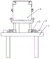
Fig. 1 is a schematic front structural view of the present invention.
Fig. 2 is a schematic diagram of the back structure of the present invention.
Fig. 3 is a schematic perspective view of the driving device of the present invention.
Fig. 4 is an internal cross-sectional view of the driving device of fig. 3 according to the present invention.
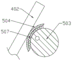
Fig. 5 is a partial view at a of fig. 2 of the present invention.
Fig. 6 is a left side view of the present invention.
In the figure: 1-test bench, 2-positioning block, 201-positioning groove, 3-clamping device, 301-hydraulic cylinder, 302-thrust plate, 303-clamping plate, 304-guide rod, 4-car seat, 401-seat plate, 402-backrest, 403-rotating shaft, 404-supporting leg, 5-driving device, 501-base, 502-servo motor, 503-eccentric cam, 504-guide sliding sleeve, 505-L-shaped plate, 506-first bolt, 507-ball, 6-supporting leg, 7-rebound device, 701-connecting seat, 702-second bolt, 703-extension spring and 704-clamping groove.
Detailed Description
In order to make the objects, technical solutions and advantages of the embodiments of the present invention clearer, the technical solutions in the embodiments of the present invention will be clearly and completely described below with reference to the drawings in the embodiments of the present invention, and it is obvious that the described embodiments are some, but not all, embodiments of the present invention. All other embodiments, which can be derived by a person skilled in the art from the embodiments given herein without making any creative effort, shall fall within the protection scope of the present invention.
In the description of the embodiments of the present invention, it should be noted that the terms "first", "second" and "third" are used for the sake of clarity in describing the numbering of the components of the product and do not represent any substantial difference, unless explicitly stated or limited otherwise. The directions of "up", "down", "left" and "right" are all based on the directions shown in the attached drawings. Specific meanings of the above terms in the embodiments of the present invention can be understood by those of ordinary skill in the art according to specific situations.
It is to be understood that, unless otherwise expressly specified or limited, the term "coupled" is used broadly, and may, for example, refer to directly coupled devices or indirectly coupled devices through intervening media. Specific meanings of the above terms in the embodiments of the invention will be understood to those of ordinary skill in the art in specific cases.
Examples
Referring to fig. 1 to 6, in an embodiment of the present invention, an automobile seat backrest overturning endurance test bed includes a test bed 1, a plurality of support legs 6 are installed at the bottom of the test bed 1, the support legs 6 are fixed on the ground, two positioning blocks 2 are installed on the test bed 1, a positioning groove 201 is formed in each positioning block 2, a clamping device 3 is installed on each positioning block 2, and the clamping device 3 includes: pneumatic cylinder 301, thrust plate 302, clamping plate 303 and guide arm 304, the quantity of pneumatic cylinder 301 is two, on pneumatic cylinder 301 was fixed in test bench 1, two pneumatic cylinder 301's telescopic link all linked to each other with thrust plate 302, thrust plate 302 is located the outside of locating piece 2, install a plurality of guide arms 304 that extend to in the constant head tank 201 and link to each other with clamping plate 303 on the thrust plate 302, guide arm 304 and 2 sliding connection of locating piece, two be connected with car seat 4 between the locating piece 2, car seat 4 includes: the seat plate 401, the backrest 402, the pivot 403 and the support leg 404, the backrest 402 is installed to the upside of seat plate 401, the backrest 402 is connected with the seat plate 401 through the pivot 403 is rotated, two support legs 404 are installed to the bottom of seat plate 401, the support leg 404 extends to the constant head tank 201, fix the support leg 404 through clamping device 3, install the drive arrangement 5 who links to each other with the backrest 402 on the test bench 1, drive arrangement 5 includes: the test bed comprises a base 501, a servo motor 502, an eccentric cam 503, a guide sliding sleeve 504, an L-shaped plate 505, a first bolt 506 and balls 507, wherein the base 501 is fixed on the test bed 1, the servo motor 502 is fixed on the base 501, the eccentric cam 503 is installed on an output shaft of the servo motor 502, the eccentric cam 503 extends into the guide sliding sleeve 504, the outer surface of the guide sliding sleeve 504 is arc-shaped, a plurality of balls 507 which are in rolling fit with the eccentric cam 503 are installed in the guide sliding sleeve 504, the guide sliding sleeve 504 is installed on the back surface of the backrest 402, the L-shaped plate 505 is welded on each of the left side and the right side of the guide sliding sleeve 504, the end of each L-shaped plate 505 is provided with a first bolt 506, the first bolts 506 are perpendicular to the side surface of the backrest 402, the L-shaped plate is fixed with the backrest 402 by screwing the first bolts 506, and the guide sliding sleeve 504 is fixed with the backrest 402, two rebound devices 7 connected with the backrest 402 are installed on the test bed 1, and the rebound devices 7 comprise: connecting seat 701, second bolt 702 and extension spring 703, seted up draw-in groove 704 in the connecting seat 701, draw-in groove 704 is inserted to the side of back 402, a second bolt 702 is all installed to the upper and lower both sides of draw-in groove 704, presss from both sides tightly back 402 through two second bolts 702 for connecting seat 701 is fixed mutually with back 402, connecting seat 701 passes through extension spring 703 and test bench 1 elastic connection.
When the automobile seat backrest overturning endurance test bed is used, firstly, two supporting legs 404 of an automobile seat 4 are placed in positioning grooves 201, a thrust plate 302 is driven to move through a hydraulic cylinder 301, a guide rod 304 is driven to move through the thrust plate 302, a clamping plate 303 is driven through the guide rod 304 to clamp the supporting legs 404, then the automobile seat 4 is fixed, then a guide sliding sleeve 504 is installed on the back surface of a backrest 402, a first bolt 506 on an L-shaped plate 505 is screwed down, the guide sliding sleeve 504 is fixed with the backrest 402, then a connecting seat 701 is installed on the backrest 402, a second bolt 702 is screwed down, the connecting seat 701 is fixed with the backrest 402, finally, a servo motor 502 is started, an eccentric cam 503 is driven to rotate through the servo motor 502, the guide sliding sleeve 504 is driven to move through the rotation of the eccentric cam 503, the backrest 402 is driven to move through the movement of the guide sliding sleeve 504, the backrest 402 is driven to swing back and forth through the pulling force of the guide sliding sleeve 504 and pulling force of the tensile spring 703, the servo motor 502 drives the backrest 402 to swing fast, which is beneficial to improving the testing efficiency.
It will be evident to those skilled in the art that the invention is not limited to the details of the foregoing illustrative embodiments, and that the present invention may be embodied in other specific forms without departing from the spirit or essential attributes thereof. The present embodiments are therefore to be considered in all respects as illustrative and not restrictive, the scope of the invention being indicated by the appended claims rather than by the foregoing description, and all changes which come within the meaning and range of equivalency of the claims are therefore intended to be embraced therein. Any reference sign in a claim should not be construed as limiting the claim concerned.
Claims (7)
1. The utility model provides a car seat back durable test platform that overturns, includes test bench (1), its characterized in that, install two locating pieces (2) on test bench (1), every a constant head tank (201), every have all been seted up in locating piece (2) all install one clamping device (3) on locating piece (2), two be connected with car seat (4) between locating piece (2), car seat (4) include: bedplate (401), back (402), pivot (403) and landing leg (404), back (402) are installed to the upside of bedplate (401), back (402) rotate with bedplate (401) through pivot (403) and are connected, two landing legs (404) are installed to the bottom of bedplate (401), landing leg (404) extend to in constant head tank (201), install drive arrangement (5) that link to each other with back (402) on test bench (1), drive arrangement (5) include: a base (501), a servo motor (502), an eccentric cam (503), a guide sliding sleeve (504), an L-shaped plate (505), a first bolt (506) and a ball (507), the machine base (501) is fixed on the test bed (1), a servo motor (502) is fixed on the machine base (501), an output shaft of the servo motor (502) is provided with an eccentric cam (503), the eccentric cam (503) extends into the guide sliding sleeve (504), a plurality of balls (507) which are matched with the eccentric cam (503) in a rolling way are arranged in the guide sliding sleeve (504), the guide sliding sleeve (504) is arranged on the back of the backrest (402), the left side and the right side of the guide sliding sleeve (504) are respectively welded with an L-shaped plate (505), the end part of each L-shaped plate (505) is provided with a first bolt (506), two rebound devices (7) connected with the backrest (402) are mounted on the test bed (1).
2. The car seat back overturning endurance test bench of claim 1, where in the bottom of the test bench (1) is mounted with a plurality of legs (6), the legs (6) being fixed on the ground.
3. The seatback rollover endurance test stand of claim 1, in which the clamping device (3) comprises: pneumatic cylinder (301), thrust plate (302), clamping plate (303) and guide arm (304), the quantity of pneumatic cylinder (301) is two, on pneumatic cylinder (301) was fixed in test bench (1), two the telescopic link of pneumatic cylinder (301) all links to each other with thrust plate (302), thrust plate (302) are located the outside of locating piece (2), install a plurality of guide arms (304) that link to each other with clamping plate (303) in extending to constant head tank (201) on thrust plate (302).
4. The automotive seat back tumble durability test stand according to claim 3, characterized in that said guide rod (304) is slidingly connected with said positioning block (2).
5. The car seat backrest overturning endurance test stand of claim 1, in which the outer surface of the guide sliding sleeve (504) is arc-shaped.
6. The automotive seat back tumble durability test stand according to claim 5, characterized in that said first bolt (506) is perpendicular to the side of the back (402).
7. The seatback rollover endurance test stand according to claim 1, wherein said rebound device (7) comprises: connecting seat (701), second bolt (702) and extension spring (703), draw-in groove (704) have been seted up in connecting seat (701), draw-in groove (704) are inserted to the side of back (402), a second bolt (702) is all installed to the upper and lower both sides of draw-in groove (704), connecting seat (701) pass through extension spring (703) and test bench (1) elastic connection.
Priority Applications (1)
| Application Number | Priority Date | Filing Date | Title |
|---|---|---|---|
| CN202110836224.6A CN113686589A (en) | 2021-07-23 | 2021-07-23 | A kind of automobile seat back flip durability test bench |
Applications Claiming Priority (1)
| Application Number | Priority Date | Filing Date | Title |
|---|---|---|---|
| CN202110836224.6A CN113686589A (en) | 2021-07-23 | 2021-07-23 | A kind of automobile seat back flip durability test bench |
Publications (1)
| Publication Number | Publication Date |
|---|---|
| CN113686589A true CN113686589A (en) | 2021-11-23 |
Family
ID=78577764
Family Applications (1)
| Application Number | Title | Priority Date | Filing Date |
|---|---|---|---|
| CN202110836224.6A Pending CN113686589A (en) | 2021-07-23 | 2021-07-23 | A kind of automobile seat back flip durability test bench |
Country Status (1)
| Country | Link |
|---|---|
| CN (1) | CN113686589A (en) |
Cited By (2)
| Publication number | Priority date | Publication date | Assignee | Title |
|---|---|---|---|---|
| CN115077941A (en) * | 2022-07-01 | 2022-09-20 | 武汉蔚泽汽车科技有限公司 | A car seat test device |
| CN116718364A (en) * | 2023-06-16 | 2023-09-08 | 广西双英集团股份有限公司 | A car rear seat back folding test device |
Citations (9)
| Publication number | Priority date | Publication date | Assignee | Title |
|---|---|---|---|---|
| CN203337389U (en) * | 2013-06-03 | 2013-12-11 | 上海延锋江森座椅有限公司 | Automobile seat backrest overturn endurance test bench |
| CN104207925A (en) * | 2014-09-22 | 2014-12-17 | 青岛蓝图文化传播有限公司市南分公司 | Automatic back-knocking massage chair |
| CN105014488A (en) * | 2014-04-23 | 2015-11-04 | 枣庄彤力机械工程有限公司 | Medium-high grinding machine for numerical control rubber roller |
| CN106525402A (en) * | 2016-11-25 | 2017-03-22 | 西德科东昌汽车座椅技术有限公司 | Automobile rear-row seat backrest folding test apparatus |
| CN107300463A (en) * | 2017-08-04 | 2017-10-27 | 江苏江测检测技术服务有限公司 | A kind of durable comprehensive test machine of motor vehicle seat back |
| CN206960102U (en) * | 2017-04-20 | 2018-02-02 | 中国检验认证集团湖北有限公司 | A kind of hand-operated automobile seat angle adjuster durable test stand |
| CN107720407A (en) * | 2017-11-09 | 2018-02-23 | 独山县玉水民族织布厂 | A kind of multi-strand yarns coiling collection device |
| CN210375732U (en) * | 2019-07-25 | 2020-04-21 | 上汽通用五菱汽车股份有限公司 | Automobile seat endurance test detection device |
| CN111238791A (en) * | 2020-03-30 | 2020-06-05 | 广西双英集团股份有限公司 | Test equipment and test methods for car seat backrest turning durability |
-
2021
- 2021-07-23 CN CN202110836224.6A patent/CN113686589A/en active Pending
Patent Citations (9)
| Publication number | Priority date | Publication date | Assignee | Title |
|---|---|---|---|---|
| CN203337389U (en) * | 2013-06-03 | 2013-12-11 | 上海延锋江森座椅有限公司 | Automobile seat backrest overturn endurance test bench |
| CN105014488A (en) * | 2014-04-23 | 2015-11-04 | 枣庄彤力机械工程有限公司 | Medium-high grinding machine for numerical control rubber roller |
| CN104207925A (en) * | 2014-09-22 | 2014-12-17 | 青岛蓝图文化传播有限公司市南分公司 | Automatic back-knocking massage chair |
| CN106525402A (en) * | 2016-11-25 | 2017-03-22 | 西德科东昌汽车座椅技术有限公司 | Automobile rear-row seat backrest folding test apparatus |
| CN206960102U (en) * | 2017-04-20 | 2018-02-02 | 中国检验认证集团湖北有限公司 | A kind of hand-operated automobile seat angle adjuster durable test stand |
| CN107300463A (en) * | 2017-08-04 | 2017-10-27 | 江苏江测检测技术服务有限公司 | A kind of durable comprehensive test machine of motor vehicle seat back |
| CN107720407A (en) * | 2017-11-09 | 2018-02-23 | 独山县玉水民族织布厂 | A kind of multi-strand yarns coiling collection device |
| CN210375732U (en) * | 2019-07-25 | 2020-04-21 | 上汽通用五菱汽车股份有限公司 | Automobile seat endurance test detection device |
| CN111238791A (en) * | 2020-03-30 | 2020-06-05 | 广西双英集团股份有限公司 | Test equipment and test methods for car seat backrest turning durability |
Cited By (2)
| Publication number | Priority date | Publication date | Assignee | Title |
|---|---|---|---|---|
| CN115077941A (en) * | 2022-07-01 | 2022-09-20 | 武汉蔚泽汽车科技有限公司 | A car seat test device |
| CN116718364A (en) * | 2023-06-16 | 2023-09-08 | 广西双英集团股份有限公司 | A car rear seat back folding test device |
Similar Documents
| Publication | Publication Date | Title |
|---|---|---|
| CN113686589A (en) | A kind of automobile seat back flip durability test bench | |
| CN201116903Y (en) | Car Seat Test Equipment | |
| CN204535978U (en) | A kind of seat fatigue behaviour multi-function test stand | |
| CN215931259U (en) | Fatigue test bench for front and rear sliding tracks of automobile seat | |
| CN106644516A (en) | Vehicle seat bumpiness creeping testing device | |
| CN103558037A (en) | Automobile seat strength test bed with single hydraulic cylinder to act | |
| CN101750203A (en) | Fatigue test stand of automobile pedals | |
| CN201600255U (en) | Automobile pedal fatigue test bed | |
| CN207788198U (en) | A kind of backrest wind spring automatic assembling mechanism | |
| CN206399663U (en) | A kind of automotive seat jolts wriggling experimental rig | |
| CN210464951U (en) | Inner diameter through detection mechanism of headrest locking guide sleeve detection line | |
| CN220764172U (en) | Leg support electric adjustable seat | |
| CN218074190U (en) | Office chair swinging base stable in use | |
| CN208784124U (en) | Headrest electric adjusting mechanism for angle | |
| CN101786224A (en) | Hole buckle devices for front and back door glass of automobile and hole buckle mounting method | |
| CN213364239U (en) | An electric vehicle drive axle test device | |
| CN222522510U (en) | Double seat overturning and adjusting mechanism | |
| CN218661471U (en) | Foldable automobile seat | |
| CN213121147U (en) | Driving chair sways testing arrangement | |
| CN205768855U (en) | A kind of have the chair framework that damping is comfortable | |
| CN216926099U (en) | Durable mechanism for automobile seat | |
| CN223361747U (en) | Headrest endurance test device | |
| CN222452018U (en) | Automobile seat structure with ISOFIX fixed point structure | |
| CN222866233U (en) | A multi-point alternating pressure durability test device for automobile seats | |
| CN223199913U (en) | Folding seat and intelligent mobile terminal |
Legal Events
| Date | Code | Title | Description |
|---|---|---|---|
| PB01 | Publication | ||
| PB01 | Publication | ||
| SE01 | Entry into force of request for substantive examination | ||
| SE01 | Entry into force of request for substantive examination | ||
| CB02 | Change of applicant information |
Address after: 224000 No. 36, Xiangjiang Road, Yancheng Economic and Technological Development Zone, Jiangsu Province Applicant after: Jiangsu Yueda Yanfeng Auto Parts Co.,Ltd. Address before: 224000 No. 36, Xiangjiang Road, Yancheng Economic and Technological Development Zone, Jiangsu Province Applicant before: JIANGSU YUEDA YANFENG ADIENT SEATING CO.,LTD. |
|
| CB02 | Change of applicant information | ||
| RJ01 | Rejection of invention patent application after publication |
Application publication date: 20211123 |
|
| RJ01 | Rejection of invention patent application after publication |