Disclosure of Invention
In view of this, the invention aims to provide a thermal management coupling performance testing system for a pure electric passenger vehicle, so as to solve the defects of large difference between a single system testing result and a real vehicle running result, time lag of a multi-system coupling performance matching verification test and large development risk in the discussion.
In order to achieve the purpose, the technical scheme of the invention is realized as follows:
a thermal management coupling performance test system for a pure electric passenger vehicle comprises a first temperature control air duct, a second temperature control air duct, an electric drive test bench, a battery temperature control box, 2 adjusting supports, a data acquisition subsystem and a main controller, wherein the first temperature control air duct is provided with a cabin temperature control box body which is fixed to the electric drive test bench;
the data acquisition subsystem comprises a tested sample data acquisition module and a platform environment information monitoring data acquisition module, the tested sample data acquisition module is installed on the tested sample, and the platform environment information monitoring data acquisition module is fixedly installed in the first temperature control air duct, the second temperature control air duct and the battery temperature control box respectively;
execution unit in the control by temperature change wind channel, No. two control by temperature change wind channels, electrically drive test bench in execution unit, the battery control by temperature change incasement execution unit, adjust in the support execution unit, by test sample data acquisition module and the equal passing signal connection of platform environmental information monitoring data acquisition module to main control unit, by test sample data acquisition module be used for monitoring the state information of being surveyed the sample, platform environmental information monitoring data acquisition module is used for monitoring the environmental information of control by temperature change wind channel, No. two control by temperature change wind channels, battery control by temperature change case.
Furthermore, the tested sample data acquisition module comprises a tested sample data acquisition instrument, a tested sample pressure sensor, a tested sample flow sensor, a tested sample current sensor, a tested sample voltage sensor and a tested sample temperature sensor, wherein the tested sample pressure sensor, the tested sample flow sensor, the tested sample current sensor, the tested sample voltage sensor and the tested sample temperature sensor are all mounted on the tested sample, the tested sample pressure sensor, the tested sample flow sensor, the tested sample current sensor, the tested sample voltage sensor and the tested sample temperature sensor are all connected to the tested sample data acquisition instrument through signals, and the tested sample data acquisition instrument is connected to the main controller through signals.
Further, platform environmental information monitoring data acquisition module includes platform environmental data collection appearance, platform environmental pressure sensor, platform environmental temperature sensor and platform environmental humidity sensor install respectively in a control by temperature change wind channel, No. two control by temperature change wind channels inside for monitor the environmental information in a control by temperature change wind channel, No. two control by temperature change wind channels, platform environmental temperature sensor still installs in battery temperature control incasement portion for monitor the environmental information of battery temperature control case, platform environmental pressure sensor, platform environmental temperature sensor and platform environmental humidity sensor all through signal connection to platform environmental data collection appearance, platform environmental data collection appearance through signal connection to main control unit.
Further, it includes that a control by temperature change wind channel is surveyed piece, No. two control by temperature change wind channels by survey piece, electricity drive test rack by survey piece and battery temperature control box by survey piece, a control by temperature change wind channel is surveyed piece, electricity drive test rack by survey piece all is located a control by temperature change wind channel, No. two control by temperature change wind channels is surveyed the piece and is located No. two control by temperature change wind channels, battery temperature control box by survey piece be located battery temperature control box, a control by temperature change wind channel is surveyed piece, No. two control by temperature change wind channel by survey piece, electricity drive test rack by survey piece and battery temperature control box by survey piece's state information all through being tested sample piece pressure sensor, being tested sample piece flow sensor, being tested sample piece current sensor, being tested sample piece voltage sensor and being tested sample piece temperature sensor monitor.
Furthermore, the first temperature control air duct also comprises a first air duct test sample piece installation section, a first air duct contraction section, a first air duct heating section, a first air duct diffusion section, a first air duct variable-frequency fan section, an air duct confluence section and 2 first air duct refrigerating sections, one side of the cabin temperature control box body is fixedly communicated with one side of the first air duct test sample piece installation section, the other side of the first air duct test sample piece installation section is fixedly communicated with the first air duct contraction section, the first air duct heating section, the first air duct diffusion section and the first air duct variable-frequency fan section in sequence, the other side of the first air duct variable-frequency fan section is fixedly communicated with the middle section of the air duct confluence section, two ends of the air duct confluence section are fixedly communicated with two first air duct refrigerating sections respectively, the other end of each first air duct refrigerating section is fixedly communicated with two sides of the cabin temperature control air duct box body respectively, a closed type backflow section is arranged in the first air duct temperature control box body, and is integrally formed into a measured piece installation tool of the cabin temperature control box body, the electric drive test bench is fixed to a control by temperature change wind channel cabin temperature control box body by a measured piece installation tool through the cabin temperature control box body, be equipped with a sample piece installation tool in the wind channel test sample piece installation section, a control by temperature change wind channel is fixed to a wind channel test sample piece installation section through a sample piece installation tool, still be equipped with platform environmental pressure sensor, platform environmental temperature sensor and platform environmental humidity sensor in the wind channel test sample piece installation section respectively for the environmental information in monitoring a control by temperature change wind channel, a wind channel heating section, a wind channel variable frequency fan section and a wind channel refrigeration section are all through signal connection to main control unit.
Further, the second temperature control air channel comprises a second air channel test sample piece installation section, a second air channel contraction section, a second air channel heating section, a second air channel variable-frequency fan section, a second air channel diffusion section and a second air channel refrigeration section, a second sample piece installation tool is arranged in the second air channel test sample piece installation section, a second temperature control air channel to be tested is fixed to the second air channel test sample piece installation section through the second sample piece installation tool, a platform environment pressure sensor, a platform environment temperature sensor and a platform environment humidity sensor are further arranged in the second air channel test sample piece installation section respectively and used for monitoring environment information of the second temperature control air channel, the second air channel test sample piece installation section is fixedly sleeved inside the cabin temperature control box body, and one side of the second air channel test sample piece installation section is sequentially and fixedly communicated to the second air channel refrigeration section, the second air channel diffusion section and the second air channel variable-frequency fan section, No. two wind channel heating sections and No. two wind channel shrinkage sections, No. two wind channel shrinkage section other ends are fixed to No. two wind channel test sample piece installation section opposite sides, No. two wind channel heating sections, No. two wind channel variable frequency fan sections, No. two wind channel refrigeration sections all through signal connection to main control unit.
Further, the battery temperature control box includes temperature control box and its inside battery temperature control box hot plate and the outside battery temperature control box cold and hot control unit of temperature control box, be equipped with battery temperature control box test appearance installation frock in the temperature control box, battery temperature control box is fixed to the battery temperature control box in through battery temperature control box appearance installation frock by the survey piece, still fixed mounting platform ambient temperature sensor in the temperature control box, platform ambient temperature sensor all is used for monitoring temperature control box internal temperature environmental information, battery temperature control box hot plate, battery temperature control box cold and hot control unit all are connected to main control unit through signal.
Further, adjust the support and include support body and 2 electric telescopic handle, the support body is the U-shaped structure, and support body joint is to control by temperature change bottom half, two electric telescopic handle of both ends difference fixed connection of support body, electric telescopic handle through signal connection to main control unit.
Compared with the prior art, the thermal management coupling performance test system for the pure electric passenger car has the following advantages:
(1) the thermal management coupling performance test system for the pure electric passenger vehicle can achieve the effect that the thermal management performance matching verification and strategy calibration test time is advanced by more than half a year, the design problem of the thermal management system is discovered earlier, and the research and development cost and risk are reduced. The integrated coupling test of the whole vehicle thermal management system can be carried out, the development trend of the high integrated coupling of the thermal management system in the future is met, and compared with the real vehicle test, the test platform is flexible in test and low in cost.
(2) The heat management coupling performance test system for the pure electric passenger vehicle has the advantages that the platform is compact in arrangement mode and integrated in components, so that the occupied area is greatly reduced, the length of a connecting pipeline of the components of the heat management system is consistent with that of an actual vehicle, the actual vehicle test can be replaced to a certain extent, errors caused by pipeline changes to the heat management performance are eliminated, and the accuracy of the test system result is ensured.
(3) According to the pure electric passenger vehicle thermal management coupling performance test system, the tested system is a complete set of thermal management system, and the platform is arranged around the real thermal management system, so that not only can the thermal load be truly embodied, but also the arrangement position relation among the tested pieces is consistent with that of a real vehicle, the coupling relation among the tested pieces can be restored, and the running condition of the real vehicle, such as the coupling relation between a radiator and a condenser, the coupling relation between the air outlet of a heat exchanger and the electric drive heat dissipation and the like, can be reflected.
Detailed Description
It should be noted that the embodiments and features of the embodiments may be combined with each other without conflict.
In the description of the present invention, it is to be understood that the terms "center", "longitudinal", "lateral", "up", "down", "front", "back", "left", "right", "vertical", "horizontal", "top", "bottom", "inner", "outer", and the like, indicate orientations or positional relationships based on those shown in the drawings, and are used only for convenience in describing the present invention and for simplicity in description, and do not indicate or imply that the referenced devices or elements must have a particular orientation, be constructed and operated in a particular orientation, and thus, are not to be construed as limiting the present invention. Furthermore, the terms "first", "second", etc. are used for descriptive purposes only and are not to be construed as indicating or implying relative importance or implicitly indicating the number of technical features indicated. Thus, a feature defined as "first," "second," etc. may explicitly or implicitly include one or more of that feature. In the description of the present invention, "a plurality" means two or more unless otherwise specified.
In the description of the present invention, it should be noted that, unless otherwise explicitly specified or limited, the terms "mounted," "connected," and "connected" are to be construed broadly, e.g., as meaning either a fixed connection, a removable connection, or an integral connection; can be mechanically or electrically connected; they may be connected directly or indirectly through intervening media, or they may be interconnected between two elements. The specific meaning of the above terms in the present invention can be understood by those of ordinary skill in the art through specific situations.
The present invention will be described in detail below with reference to the embodiments with reference to the attached drawings.
As shown in figures 1 to 8, the thermal management coupling performance testing system for the pure electric passenger car comprises a temperature control air duct 1, a temperature control air duct 2, an electric drive testing rack 3, a battery temperature control box 4, 2 adjusting supports 5, a data acquisition subsystem and a main controller, wherein the temperature control air duct 1 is provided with a cabin temperature control box body 11, the cabin temperature control box body 11 is fixed on the electric drive testing rack 3, the temperature control air duct 2 is fixedly sleeved at the top of the temperature control air duct 1, the pipeline environment of the temperature control air duct 1 and the pipeline environment of the temperature control air duct 2 are isolated and independent from each other, the battery temperature control box 4 is arranged above the electric drive testing rack 3, two adjusting supports 5 are respectively arranged on two sides of the bottom of the battery temperature control box 4, and the data acquisition subsystem is respectively equipped with the temperature control air duct 1, the temperature control air duct 2 and the electric drive testing rack 3, The battery temperature control box 4;
the data acquisition subsystem comprises a tested sample data acquisition module and a platform environment information monitoring data acquisition module, the tested sample data acquisition module is installed on the tested sample, and the platform environment information monitoring data acquisition module is respectively and fixedly installed inside the first temperature control air duct 1, the second temperature control air duct 2 and the battery temperature control box 4; the data acquisition subsystem can acquire information such as temperature, pressure, working medium flow, current, voltage, power consumption and the like during system operation.
Execution unit in execution unit, No. two control by temperature change wind channel 2 in execution unit, the electricity drive test bench frame 3 in execution unit, battery control by temperature change case 4 in execution unit, the regulation support 5 in execution unit, by test sample data acquisition module and the equal through signal connection to main control unit of platform environmental information monitoring data acquisition module, by test sample data acquisition module be used for monitoring the state information of being surveyed the sample, platform environmental information monitoring data acquisition module is used for monitoring the environmental information of a control by temperature change wind channel 1, No. two control by temperature change wind channel 2, battery control by temperature change case 4. For example, for setting test conditions such as temperature, humidity, wind speed, electric drive speed, torque, etc. The main controller is an upper computer. The test system can realize that the time for matching verification of the thermal management performance and the time for a strategy calibration test are more than half a year ahead, the design problem of the thermal management system is discovered earlier, and the research and development cost and risk are reduced. Compare with the real vehicle test, test platform is experimental nimble, with low costs, and the test bench 3 that drives electrically is prior art, and the test bench 3 that drives electrically drives including the test electricity, is driven, parts such as output shaft, gear box are driven to the quilt, and it aims at providing the electric system work load that drives under the different operating modes. The platform is compact in arrangement mode, the length of a connecting pipeline of the heat management system components is consistent with that of a real vehicle, errors caused by pipeline changes to heat management performance are eliminated, and the accuracy of a test system result is ensured.
The test system can provide environmental boundary conditions similar to those of a real vehicle for a battery system, an electric drive system, an air conditioning system and a cooling system, and the arrangement form of the tested heat management system is consistent with that of the whole vehicle. The vehicle thermal management performance can be reduced to the maximum extent under the actual vehicle running state.
The tested sample piece data acquisition module comprises a tested sample piece data acquisition instrument, a tested sample piece pressure sensor, a tested sample piece flow sensor, a tested sample piece current sensor, a tested sample piece voltage sensor and a tested sample piece temperature sensor, wherein the tested sample piece pressure sensor, the tested sample piece flow sensor, the tested sample piece current sensor, the tested sample piece voltage sensor and the tested sample piece temperature sensor are all installed on the tested sample piece, the tested sample piece pressure sensor, the tested sample piece flow sensor, the tested sample piece current sensor, the tested sample piece voltage sensor and the tested sample piece temperature sensor are all connected to the tested sample piece data acquisition instrument through signals, and the tested sample piece data acquisition instrument is connected to the main controller through signals. The tested sample piece data acquisition instrument, the tested sample piece temperature sensor, the tested sample piece pressure sensor, the tested sample piece flow sensor, the tested sample piece current sensor and the tested sample piece voltage sensor are all the prior art, the tested sample piece pressure sensor, the tested sample piece flow sensor, the tested sample piece current sensor, the tested sample piece voltage sensor and the tested sample piece temperature sensor are used for monitoring the temperature, the pressure, the flow, the current and the voltage of the tested sample piece, and during an actual test, an acquisition system acquires the state information of the tested sample piece in real time and feeds an acquisition result back to a main controller.
Platform environmental information monitoring data acquisition module includes platform environmental data collection appearance, platform environmental pressure sensor, platform environmental temperature sensor and platform environmental humidity sensor install respectively in a control by temperature change wind channel 1, No. two control by temperature change wind channel 2 insides for monitor a control by temperature change wind channel 1, No. two control by temperature change wind channel 2's environmental information, platform environmental temperature sensor still installs in battery temperature control box 4 inside for monitor battery temperature control box 4's temperature environmental information, all through signal connection to platform environmental data collection appearance, platform environmental data collection appearance through signal connection to main control unit. Platform environmental data gathers appearance, platform ambient temperature sensor, platform ambient pressure sensor and platform ambient humidity sensor are prior art, platform ambient temperature sensor, platform ambient pressure sensor and platform ambient humidity sensor are used for monitoring control by temperature change wind channel 1 No. two, the temperature in control by temperature change wind channel 2, the flow, humidity, and monitor the temperature environment information of battery temperature control box 4 simultaneously, when actual test, the inside platform environmental information monitoring PID system of main control unit carries out computational analysis to the platform environmental information data of gathering, and feed back the calculated result to the executive component.
Tested sample piece includes that control by temperature change wind channel is tested piece, No. two control by temperature change wind channels are tested piece, electricity drive test rack is tested piece and battery temperature control box and is tested the piece, control by temperature change wind channel is tested piece, electricity drive test rack is tested the piece and is all located control by temperature change wind channel 1, No. two control by temperature change wind channels are tested the piece and are located control by temperature change wind channel 2 No. two, battery temperature control box is tested the piece and is located battery temperature control box 4, control by temperature change wind channel is tested piece, No. two control by temperature change wind channel is tested piece, electricity drive test rack is tested piece and battery temperature control box and is tested the state information of piece and all monitored through being tested sample piece pressure sensor, being tested sample piece flow sensor, being tested sample piece current sensor, being tested sample piece voltage sensor and being tested sample piece temperature sensor, control by temperature change wind channel is tested the piece and is including radiator, condenser, fan, compressor, The water pump, the valve body, the storage battery and the like, the second temperature control air channel tested piece comprises an evaporator, a built-in condenser and a wind-heating PTC, the electric drive test bench tested piece comprises a tested electric drive, and the battery temperature control box tested piece is a battery.
The first temperature control air duct 1 also comprises an air duct test sample piece installation section 12, an air duct contraction section 13, an air duct heating section 14, an air duct diffusion section 15, an air duct frequency conversion fan section 16, an air duct confluence section 17 and 2 air duct refrigeration sections 18, one side of the cabin temperature control box body 11 is fixedly communicated with one side of the air duct test sample piece installation section 12, the other side of the air duct test sample piece installation section 12 is fixedly communicated with the air duct contraction section 13, the air duct heating section 14, the air duct diffusion section 15 and the air duct frequency conversion fan section 16 in sequence, the other side of the air duct frequency conversion fan section 16 is fixedly communicated with the middle section of the air duct confluence section 17, two ends of the air duct confluence section 17 are respectively and fixedly communicated with the two air duct refrigeration air duct sections 18, and the other end of each air duct section 18 is respectively and fixedly communicated with two sides of the cabin temperature control box body 11, the whole closed return air duct that forms, be equipped with cabin accuse temperature box quilt survey piece installation frock in an wind channel cabin accuse temperature box 11, the electricity drives test bench and is surveyed the piece and pass through cabin accuse temperature box quilt survey piece installation frock fixed to a control by temperature change wind channel cabin accuse temperature box 11, be equipped with a sample piece installation frock in an air channel test sample piece erection section 12, a control by temperature change wind channel is surveyed the piece and is fixed to an air channel test sample piece erection section 12 through a sample piece installation frock, still be equipped with platform environmental pressure sensor, platform environmental temperature sensor and platform environmental humidity transducer in the air channel test sample piece erection section 12 respectively for monitor the environmental information in control by temperature change wind channel 1, an air channel heating section 14, an air channel frequency conversion fan section 16 and an air channel refrigeration section 18 all through signal connection to main control unit. In a specific embodiment, a temperature control air channel tested piece comprises a tested sample piece radiator, a condenser, a fan, a compressor, a water pump, a valve body, a storage battery and the like, a worker can set a platform environment pressure sensor, a platform environment temperature sensor and a platform environment humidity sensor at a position 150mm in front of the incoming flow of the sample piece in an air channel test sample piece installation section 12, a cabin temperature control box body 11 aims to provide a cabin environment similar to the real-vehicle operation for a cabin part, and the cabin temperature is adjusted to be a target temperature by controlling a refrigerating and heating system. The box body is communicated with the radiator and the condenser air duct. Air side outlet air of the radiator and the condenser enters the cabin temperature control box body 11, flows through parts in the cabin, flows into the radiator and the condenser air duct from two sides of the rear tail part of the cabin temperature control box body 11, and circulates in the way; the first air channel test sample piece mounting section 12 is detachably connected with the cabin temperature control box body 11, so that a radiator and a condenser are conveniently arranged in the first air channel test sample piece mounting section 12, therefore, a related test is carried out, the first air channel contraction section 13 is of a bottleneck-shaped structure, so that the first air channel contraction section 13 is used for accelerating air flow, a heater is arranged in the first air channel heating section 14, under the high-temperature working condition, the heater in the first air channel heating section 14 is turned on to provide high-temperature air inlet for a radiator and a condenser, the first air channel diffusion section 15 is used for reducing the speed of air flow, the first air channel variable-frequency fan section 16 is used for placing a fan, the air flow enters the first air channel variable-frequency fan section 16 through the first air channel refrigeration section 18 to be blown into the radiator again, the air flow enters the cabin temperature control box body 11 after the condenser, and a refrigeration unit is arranged in the first air channel refrigeration section 18 to provide stable continuous low-temperature air inlet for the radiator and the condenser.
In actual test, in order to accurately measure the heat exchange capacity of the radiator and the condenser, an air supply and temperature control air duct needs to be built, and air flow with the same air temperature and flow as those of an actual vehicle during operation is provided. In order to ensure the air supply quality and stability, the air duct comprises an air duct test sample piece installation section 12, an air duct contraction section 13, an air duct heating section 14, an air duct diffusion section 15, an air duct variable-frequency fan section 16, an air duct confluence section 17 and 2 air duct refrigerating sections 18. In order to ensure the quality of the air inlet flow field, the ratio of the axial length of the cabin temperature control box body 11 to the Z-direction height of the air channel inlet is 2.6. When the system operates, the target flow air flow is provided for the radiator and the condenser by changing the rotating speed of the variable frequency fan, and the target temperature and humidity air flow is provided for the radiator and the condenser by the cold and warm main controller and the humidity control assembly.
The second temperature control air duct 2 comprises a second air duct test sample piece installation section, a second air duct contraction section 21, a second air duct heating section, a second air duct variable frequency fan section, a second air duct diffusion section 22 and a second air duct refrigeration section 23, a second sample piece installation tool is arranged in the second air duct test sample piece installation section, a second temperature control air duct tested piece is fixed to the second air duct test sample piece installation section through the second sample piece installation tool, a platform environment pressure sensor, a platform environment temperature sensor and a platform environment humidity sensor are further arranged in the second air duct test sample piece installation section respectively and used for monitoring environment information of the second temperature control air duct 2, the second air duct test sample piece installation section is fixedly sleeved inside the cabin temperature control box body 11, and one side of the second air duct test sample piece installation section is fixedly communicated with the second air duct diffusion section 23, the second air duct diffusion section 22, The air supply device comprises a second air channel variable-frequency fan section, a second air channel heating section and a second air channel contraction section 21, wherein the other end of the second air channel contraction section 21 is fixed to the other side of a second air channel test sample piece installation section, the second air channel heating section, the second air channel variable-frequency fan section and the second air channel refrigerating section 23 are all connected to a main controller through signals, a second temperature control air channel 2 is a temperature control air channel for supplying air to an evaporator, a built-in condenser and a hot air heater PTC, and a temperature control air channel for supplying air to the evaporator, the built-in condenser and the hot air heater PIC needs to be set up for accurately measuring the heat exchange capacity of the evaporator and the built-in condenser and aims to provide the same air blowing amount and air temperature as those of an air blower. When the system is in operation, the target flow air flow is provided for the evaporator, the built-in condenser and the air heating PTC by changing the rotating speed of the variable frequency fan, and the target temperature and humidity air flow is provided for the evaporator, the built-in condenser and the air heating PTC by controlling the cooling and heating system and the humidity control assembly.
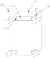
The battery temperature control box 4 comprises a temperature control box body 41, a battery temperature control box heating plate arranged inside the temperature control box body 41, and a battery temperature control box cooling and heating control unit arranged outside the temperature control box body 41, wherein a battery temperature control box test sample piece installation tool is arranged in the temperature control box body 41, a tested piece of the battery temperature control box is fixed in the battery temperature control box 4 through the battery temperature control box sample piece installation tool, a platform environment temperature sensor is fixedly arranged in the temperature control box body 41 and is used for monitoring temperature environment information in the temperature control box body 41, the battery temperature control box heating plate and the battery temperature control box cooling and heating control unit are both connected to a main controller through signals, the battery temperature control box heating plate and the cooling and heating control component are the prior art, the temperature control box body 41 comprises a battery temperature control box heating plate and a cooling and heating control component arranged at the bottom of the box body, and the battery aims at providing a cooling and heating environment under a test working condition, the heating plate of the battery temperature control box at the bottom of the box body simulates the heat radiation of the asphalt ground to the battery, the current sensor and the voltage sensor of the tested sample piece are used for collecting the current and the voltage of the battery, and the battery mounting bracket is 200mm away from the heating plate of the battery temperature control box. The battery temperature control box 4 is installed on one side of the adjusting bracket 5, so that the battery temperature control box 4 can be conveniently moved, in addition, in the specific embodiment, if the vehicle model is developed in an early stage, no battery real sample exists, so that the staff can also use the existing heating unit or power supply plate to replace the battery to be tested so as to simulate the power supply and heat generation conditions of the battery, and further replace the battery so as to facilitate the operation of the platform testing system.
Adjust support 5 and include support body 51 and 2 electric telescopic handle 52, support body 51 is the U-shaped structure, and support body 51 joint is to control by temperature change box 41 bottom, two electric telescopic handle 52 of support body 51's both ends difference fixed connection, and electric telescopic handle 52 is through signal connection to main control unit, and support body 51 joint to draw-in groove 42 to be located elasticity lagging 421 below, adjust support 5 and can carry out longitudinal movement. The power extension pole 52 is conventional and is secured to a wall on one side of the platform. If the installation test drives when electrically, the staff controls electric telescopic handle 52 at the operation interface of main control unit and begins work, moves 600mm with battery temperature control box 4 backward through electric telescopic handle 52.
Two clamping grooves 42 are respectively formed in two sides of the bottom of the temperature control box body 41, an elastic sleeve plate 421 is respectively arranged in each clamping groove 42, two wrenches 422 are respectively arranged on two sides of each elastic sleeve plate 421, the cross section of each clamping groove 42 is of a T-shaped structure, and in addition, in the specific embodiment, because the battery temperature control box 4 has a certain weight, the elastic sleeve plates 421 can be removed without adopting the elastic sleeve plates 421.
The elastic sleeve plate 421 comprises a fixed sleeve plate 4211, a movable sleeve plate 4212 and a plurality of spring bodies 4213, one end of the fixed sleeve plate 4211 is fixedly clamped to the inner wall of the clamping groove 42, the other end of the fixed sleeve plate 4211 is connected to the movable sleeve plate 4212 in a sliding manner, two wrenches 422 are respectively and fixedly connected to two sides of the movable sleeve plate 4212, the fixed sleeve plate 4211 and the movable sleeve plate 4212 are both of a hollow structure, the two are communicated with each other to form a cavity structure, a plurality of spring bodies 4213 are uniformly distributed in the cavity structure, the elastic sleeve plate 421 is used for clamping the adjusting bracket 5, the wrench 422 is convenient for workers to contract the elastic sleeve plate 421 so as to put the adjusting bracket 5 in, when the adjusting bracket 5 is installed, a worker moves the wrench 422 in the direction close to the fixed sleeve plate 4211 by hand to keep the wrench from loosening, then the staff will adjust in support 5 installs to draw-in groove 42, then the staff looses the hand again, and elasticity lagging 421 just can be in draw-in groove 42 with elasticity lagging 421 joint under the elastic action of spring body 4213.
The installation process and the test process of the thermal management coupling performance test system for the pure electric passenger car are as follows:
the space among all parts of the heat management system is limited under the actual pipeline and arrangement mode, and great challenge is brought to the arrangement of a test system. The test system adopts a 'compact' arrangement mode which is expanded around the tested system, the pipeline and the connection mode of the test system are consistent with the real vehicle state, the action of the execution component of the thermal management system is controlled by the tested sample controller, and the coupling relation and the installation mode among the subsystem components are fully considered, so that the thermal management performance under the real vehicle state can be reproduced to the maximum extent. The test system employs the following mounting arrangement.
The first air channel test sample piece installation section 12 is communicated with the cabin temperature control box body 11, and airflow flows into the cabin temperature control box body 11 through a radiator and a condenser, flows out of two sides of the rear part of the cabin temperature control box body 11, enters the first air channel variable frequency fan section 16 through the first air channel refrigeration section 18, is blown into the radiator and the condenser again, and then enters the cabin temperature control box body 11. The circulation is repeated, so that an environment boundary similar to a real vehicle is continuously provided for the radiator, the condenser and the cabin component, and the cabin temperature control box body 11 is integrally installed on the electric drive test bench 3. No. two control by temperature change wind channel 2 arranges in cabin accuse temperature box 11 back upper place, and its pipeline environment and 11 environment of cabin accuse temperature box are isolated independently each other. The battery temperature control box 4 is arranged behind the cabin temperature control box body 11, is arranged above the adjusting bracket 5 and can move longitudinally. If the test electric driver needs to be installed, the battery temperature control box 4 can be moved backwards by 600 mm.
The tested part is a pure electric passenger vehicle heat management system, a radiator, a condenser and a fan are installed in a first air channel test sample piece installation section 12 before the test is started, the tested electric drive system, a compressor, a water pump and other parts are installed in a cabin temperature control box body 11, an evaporator, a built-in condenser and a wind heating PTC are installed in a second air channel test sample piece installation section, and a battery is installed in a battery temperature control box 4. In addition, the working condition to be measured and the environmental boundary condition are led into the main controller, so that the automatic control of the system is realized.
After the test is started, a worker operates the main controller on an operation interface of the main controller, and sends instructions to each execution component through the main controller, so that environmental boundary conditions similar to the whole vehicle are provided for the tested thermal management system. The test electricity that drives test bench 3 drives among the pair dragging test system drives to receive the instruction that comes from main control unit, drives through output shaft and gear box for being surveyed and provide the load under the different operating modes, guarantees to drive the test bench 3's that the electricity drives the system and moves according to presetting the operating mode. The radiator and the condenser air supply temperature control air duct (a temperature control air duct 1) provide air inlet with air temperature, air quantity and humidity matched with the test working condition for the radiator and the condenser. The evaporator, the built-in condenser and the air heating PTC air supply temperature control air channel (a second temperature control air channel 2) provide air temperature, air quantity and humidity which are consistent with the actual conditions for the evaporator, the built-in condenser and the air heating PTC.
Under the high-temperature working condition (the platform environment temperature sensor detects signals and sends the signals to the main controller), the main controller controls the heater in the first air channel heating section 14 to be started, and high-temperature air is supplied to the radiator and the condenser. When the cabin return air temperature exceeds the required air supply temperature (the platform environment temperature sensor detects signals and sends the signals to the main controller), the main controller controls the opening of the unit in the first air duct refrigerating section 18 so as to achieve the purpose of continuously providing continuous stable air temperature for the radiator and the condenser, and the working mode of the evaporator, the built-in condenser and the air heating PTC air duct (the second temperature control air duct 2) under the high-temperature working condition is consistent with that of the radiator air duct (the first temperature control air duct 1). The main controller controls the heating plate of the battery temperature control box in the battery temperature control box 4 to simulate the asphalt ground, and provides thermal radiation environmental conditions for the battery.
Under the low temperature operating mode (platform ambient temperature sensor carries out the detected signal to give main control unit with the signal), main control unit control wind channel refrigeration section 18 internal unit is opened, provides stable continuous low temperature air inlet for radiator and condenser, and the working method under the low temperature operating mode of evaporimeter, built-in condenser and warm-by-air PTC wind channel (No. two control by temperature change wind channels 2) is unanimous with the working method under the low temperature operating mode of radiator wind channel (No. one control by temperature change wind channel 1). The main controller controls the cooling unit in the battery temperature control box 4 to be started, and provides target low-temperature environmental conditions for the battery. In the test process, the plurality of sensors collect information such as temperature, pressure, flow velocity, current, voltage and the like of all parts in the system in real time and transmit the information back to the data acquisition instrument, and the data acquisition instrument transmits signals to the main controller until the test is completed.
The above description is only for the purpose of illustrating the preferred embodiments of the present invention and is not to be construed as limiting the invention, and any modifications, equivalents, improvements and the like that fall within the spirit and principle of the present invention are intended to be included therein.