CN113685889B - Water and heat simultaneous delivery asymmetric flow circulation system - Google Patents
Water and heat simultaneous delivery asymmetric flow circulation system Download PDFInfo
- Publication number
- CN113685889B CN113685889B CN202110994433.3A CN202110994433A CN113685889B CN 113685889 B CN113685889 B CN 113685889B CN 202110994433 A CN202110994433 A CN 202110994433A CN 113685889 B CN113685889 B CN 113685889B
- Authority
- CN
- China
- Prior art keywords
- unit
- water
- communicated
- heat
- water inlet
- Prior art date
- Legal status (The legal status is an assumption and is not a legal conclusion. Google has not performed a legal analysis and makes no representation as to the accuracy of the status listed.)
- Active
Links
- XLYOFNOQVPJJNP-UHFFFAOYSA-N water Substances O XLYOFNOQVPJJNP-UHFFFAOYSA-N 0.000 title claims abstract description 285
- 238000010438 heat treatment Methods 0.000 claims abstract description 125
- 238000010992 reflux Methods 0.000 claims abstract description 64
- 238000002347 injection Methods 0.000 claims description 13
- 239000007924 injection Substances 0.000 claims description 13
- 238000001704 evaporation Methods 0.000 claims description 11
- 230000008020 evaporation Effects 0.000 claims description 11
- 238000010521 absorption reaction Methods 0.000 claims description 8
- 230000006835 compression Effects 0.000 claims description 7
- 238000007906 compression Methods 0.000 claims description 7
- 238000004891 communication Methods 0.000 claims description 2
- 230000001351 cycling effect Effects 0.000 claims 3
- 230000001360 synchronised effect Effects 0.000 claims 1
- 238000000034 method Methods 0.000 abstract description 8
- 230000008569 process Effects 0.000 abstract description 7
- 239000008236 heating water Substances 0.000 abstract 1
- 238000010612 desalination reaction Methods 0.000 description 13
- 239000000243 solution Substances 0.000 description 11
- 239000013535 sea water Substances 0.000 description 10
- 239000013505 freshwater Substances 0.000 description 9
- 238000012546 transfer Methods 0.000 description 9
- 238000010586 diagram Methods 0.000 description 4
- 238000005265 energy consumption Methods 0.000 description 3
- 238000005516 engineering process Methods 0.000 description 3
- 238000004458 analytical method Methods 0.000 description 2
- 238000004519 manufacturing process Methods 0.000 description 2
- 230000007246 mechanism Effects 0.000 description 2
- -1 and therefore Substances 0.000 description 1
- 238000013459 approach Methods 0.000 description 1
- 230000008094 contradictory effect Effects 0.000 description 1
- 239000012153 distilled water Substances 0.000 description 1
- 239000003651 drinking water Substances 0.000 description 1
- 235000020188 drinking water Nutrition 0.000 description 1
- 238000007701 flash-distillation Methods 0.000 description 1
- 238000009776 industrial production Methods 0.000 description 1
- 238000012986 modification Methods 0.000 description 1
- 230000004048 modification Effects 0.000 description 1
- 238000012545 processing Methods 0.000 description 1
- 238000005057 refrigeration Methods 0.000 description 1
- 238000005507 spraying Methods 0.000 description 1
Images




Classifications
-
- F—MECHANICAL ENGINEERING; LIGHTING; HEATING; WEAPONS; BLASTING
- F24—HEATING; RANGES; VENTILATING
- F24D—DOMESTIC- OR SPACE-HEATING SYSTEMS, e.g. CENTRAL HEATING SYSTEMS; DOMESTIC HOT-WATER SUPPLY SYSTEMS; ELEMENTS OR COMPONENTS THEREFOR
- F24D17/00—Domestic hot-water supply systems
- F24D17/02—Domestic hot-water supply systems using heat pumps
-
- F—MECHANICAL ENGINEERING; LIGHTING; HEATING; WEAPONS; BLASTING
- F24—HEATING; RANGES; VENTILATING
- F24D—DOMESTIC- OR SPACE-HEATING SYSTEMS, e.g. CENTRAL HEATING SYSTEMS; DOMESTIC HOT-WATER SUPPLY SYSTEMS; ELEMENTS OR COMPONENTS THEREFOR
- F24D19/00—Details
- F24D19/10—Arrangement or mounting of control or safety devices
- F24D19/1006—Arrangement or mounting of control or safety devices for water heating systems
- F24D19/1051—Arrangement or mounting of control or safety devices for water heating systems for domestic hot water
- F24D19/1054—Arrangement or mounting of control or safety devices for water heating systems for domestic hot water the system uses a heat pump
-
- Y—GENERAL TAGGING OF NEW TECHNOLOGICAL DEVELOPMENTS; GENERAL TAGGING OF CROSS-SECTIONAL TECHNOLOGIES SPANNING OVER SEVERAL SECTIONS OF THE IPC; TECHNICAL SUBJECTS COVERED BY FORMER USPC CROSS-REFERENCE ART COLLECTIONS [XRACs] AND DIGESTS
- Y02—TECHNOLOGIES OR APPLICATIONS FOR MITIGATION OR ADAPTATION AGAINST CLIMATE CHANGE
- Y02A—TECHNOLOGIES FOR ADAPTATION TO CLIMATE CHANGE
- Y02A20/00—Water conservation; Efficient water supply; Efficient water use
- Y02A20/124—Water desalination
Landscapes
- Engineering & Computer Science (AREA)
- Physics & Mathematics (AREA)
- Thermal Sciences (AREA)
- Chemical & Material Sciences (AREA)
- Combustion & Propulsion (AREA)
- Mechanical Engineering (AREA)
- General Engineering & Computer Science (AREA)
- Heat Treatment Of Water, Waste Water Or Sewage (AREA)
Abstract
The invention provides a hydrothermal simultaneous-delivery asymmetric flow circulation system, relates to the technical field of heat supply, and aims to solve the problem of energy loss caused by the fact that heat generated in a water treatment process cannot be fully utilized to a certain extent. The invention provides a hydrothermal simultaneous transport asymmetric flow circulation system, which comprises a water supply device, a first heating unit, a using unit, a reflux heating unit and a heat pump device, wherein the first heating unit is used for heating water; the water supply device is communicated with the water inlet end of the first heating unit through a first conveying pipe group, and the water outlet end of the first heating unit is communicated with the water inlet end of the using unit; the using unit comprises a heat using unit and a water using unit, the water outlet end of the first heating unit is communicated with the water inlet end of the heat using unit, the water outlet end of the heat using unit is connected with the water inlet end of the water using unit, the water outlet end of the water using unit is communicated with the water inlet end of the reflux heating unit, the water outlet end of the reflux heating unit is communicated with the water inlet end of the heat pump device, and the water outlet end of the heat pump device is communicated with the first conveying pipe group.
Description
Technical Field
The invention relates to the technical field of heat supply, in particular to a hydrothermal simultaneous-delivery asymmetric flow circulation system.
Background
With the increasing shortage of fresh water resources, the seawater desalination technology has been widely developed and applied. The seawater desalination, namely the seawater desalination is utilized to produce fresh water, is an open source increment technology for realizing the utilization of water resources, can increase the total amount of the fresh water, is not influenced by space, time and climate, and can ensure stable water supply such as drinking water of coastal residents, water replenishing of industrial boilers and the like.
In the process of seawater desalination, a large amount of heat is generated, but the heat generated in the desalination process is not utilized correspondingly at the present stage, so that great energy loss is caused. In addition, the application range and the approach of the fresh water resource after seawater desalination are relatively narrow at the present stage, so that the application of the seawater desalination technology cannot be better popularized and implemented.
Therefore, it is desirable to provide a hydrothermal co-delivery asymmetric flow circulation system to solve the problems in the prior art to some extent.
Disclosure of Invention
The invention aims to provide a hydrothermal simultaneous-delivery asymmetric flow circulation system, which aims to solve the problem of energy loss caused by the fact that heat generated in a water treatment process cannot be fully utilized to a certain extent.
The invention provides a hydrothermal simultaneous-delivery asymmetric flow circulation system which comprises a water supply device, a first heating unit, a using unit, a reflux heating unit and a heat pump device, wherein the water supply device is connected with the first heating unit through a pipeline; the water supply device is communicated with the water inlet end of the first heating unit through a first conveying pipe group, and the water outlet end of the first heating unit is communicated with the water inlet end of the using unit; the using unit comprises a heat using unit and a water using unit, the water outlet end of the first heating unit is communicated with the water inlet end of the heat using unit, the water outlet end of the heat using unit is connected with the water inlet end of the water using unit, the water outlet end of the water using unit is communicated with the water inlet end of the reflux heating unit, the water outlet end of the reflux heating unit is communicated with the water inlet end of the heat pump device, and the water outlet end of the heat pump device is communicated with the first conveying pipe group.
The heat using unit comprises a primary heat using unit and a secondary heat using unit, the water inlet end of the primary heat using unit is communicated with the first heating unit, the first water outlet end of the primary heat using unit is connected with the water inlet end of the secondary heat using unit, and the second water outlet end of the primary heat using unit is communicated with the water inlet end of the water using unit.
Specifically, a second conveying pipe group is arranged between the water outlet end of the first heating unit and the water inlet end of the using unit, and the second conveying pipe group is communicated with a front end using unit; the front end use unit comprises a first demand unit, and a circulation medium of the first demand unit is hot water.
Furthermore, a front end water inlet unit is communicated with the second conveying pipe group.
The front end use unit further comprises a second demand unit, and the second demand unit is communicated with the second conveying pipe group; the second demand unit comprises a flash evaporation device and a steam using unit, a first end of the flash evaporation device is communicated with the second conveying pipe group, and a second end of the flash evaporation device is communicated with the steam using unit.
Specifically, the second demand unit further includes an injection device and a high-pressure steam using unit; and the third end of the flash evaporation device is communicated with the first end of the injection device, and the second end of the injection device is communicated with the high-pressure steam using unit.
The hydrothermal co-delivery asymmetric flow circulation system further comprises a second heating unit, and the second heating unit is arranged between the first heating unit and the heat utilization unit.
Specifically, a reflux conveying pipe group is arranged between the water outlet end of the water using unit and the reflux heating unit; the reflux heating unit comprises a reflux heating device, the water inlet end of the reflux heating device is communicated with the reflux conveying pipe group, the water outlet end of the reflux heating device is communicated with the heat pump device, and the reflux heating unit is used for heating low-temperature water refluxed in the reflux conveying pipe group and conveying the low-temperature water to the heat pump device.
Furthermore, the reflux heating unit also comprises a reflux water inlet device, and the water outlet end of the reflux water inlet device is communicated with the reflux conveying pipe group.
Further, the heat pump device includes a compression type heat pump and an absorption type heat pump.
Compared with the prior art, the hydrothermal simultaneous-input asymmetric flow circulation system provided by the invention has the following advantages:
the invention provides a hydrothermal simultaneous-delivery asymmetric flow circulation system which comprises a water supply device, a first heating unit, a using unit, a reflux heating unit and a heat pump device, wherein the water supply device is connected with the first heating unit; the water supply device is communicated with the water inlet end of the first heating unit through a first conveying pipe group, and the water outlet end of the first heating unit is communicated with the water inlet end of the using unit; the using unit comprises a heat using unit and a water using unit, the water outlet end of the first heating unit is communicated with the water inlet end of the heat using unit, the water outlet end of the heat using unit is connected with the water inlet end of the water using unit, the water outlet end of the water using unit is communicated with the water inlet end of the reflux heating unit, the water outlet end of the reflux heating unit is communicated with the water inlet end of the heat pump device, and the water outlet end of the heat pump device is communicated with the first conveying pipe group.
From this analysis, it can be known that the water supply device provides the water source to the first heating unit, heats the water source through the first heating unit, and the heat of the first heating unit in this application comes from the heat that produces in the water treatment process.
The hot water heated by the first heating unit flows to the heat using unit, which is a general term for a large-scale hot water using unit and can include all heat using units requiring higher-temperature hot water.
The heat carried by the hot water passing through the heat using unit is consumed to lower the temperature of the water and flows to the water using unit. The water units in this application may include industrial and process water units or domestic water units. Therefore, it can be understood that the heat carried by the hot water after passing through the heat unit is consumed, thereby providing water resources for a unit having a certain water demand, such as a factory or a home.
Moreover, as the reflux conveying pipe group is communicated between the water using unit and the reflux heating unit, when the water using demand of the water using unit is small, the water using unit can directly enter the reflux heating unit through the reflux conveying pipe group, and the circulation of water resources is realized.
The low-temperature water entering the reflux heating unit is heated for the first time, so that the low-temperature water is heated to a certain degree, then flows to the heat pump device, is circularly refluxed to the first conveying pipe group through further heating of the heat pump device, and enters the first heating unit together with the fresh water supplied by the water supply device for heating.
According to the water-heat co-transmission asymmetric flow circulation system, water resources and heat generated in the sea water desalination process are utilized, required hot water resources can be provided for factories and families with heat demands, the application range of the fresh water resources after sea water desalination is widened, and the fresh water resources can be further circulated and recycled through the arrangement of the reflux heating unit and the heat pump device, so that the use cost is reduced, and the resource utilization rate is improved.
Drawings
In order to more clearly illustrate the embodiments of the present invention or the technical solutions in the prior art, the drawings used in the embodiments or the prior art descriptions will be briefly described below, and it is obvious that the drawings in the following description are some embodiments of the present invention, and other drawings can be obtained by those skilled in the art without creative efforts.
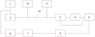
Fig. 1 is a schematic structural view of a hydrothermal co-output asymmetric flow circulation system according to a first embodiment of the present invention;
fig. 2 is a schematic structural view of a hydrothermal simultaneous transport asymmetric flow circulation system according to a second embodiment of the present invention;
FIG. 3 is a schematic structural diagram of a hydrothermal co-delivery asymmetric flow circulation system according to a third embodiment of the present invention;
FIG. 4 is a schematic structural diagram of a hydrothermal co-delivery asymmetric flow circulation system according to a fourth embodiment of the present invention;
fig. 5 is a schematic structural view of a hydrothermal simultaneous transport asymmetric flow circulation system according to a fifth embodiment of the present invention;
fig. 6 is a schematic structural view of a hydrothermal simultaneous transport asymmetric flow circulation system according to a sixth embodiment of the present invention;
fig. 7 is a schematic structural view of a hydrothermal simultaneous transport asymmetric flow circulation system according to a seventh embodiment of the present invention;
fig. 8 is a schematic structural view of a hydrothermal co-delivery asymmetric flow circulation system according to an eighth embodiment of the present invention.
In the figure: 1-a water supply device; 2-a first heating unit; 3-primary heat unit; 4-a secondary thermal unit; 5-a water using unit; 6-a reflux heating device; 7-a compression heat pump; 8-an absorption heat pump; 9-a first transfer tubing set; 10-a second transfer tubing set; 11-a first demand unit; 12-a front end water inlet unit; 13-a flash distillation unit; 14-a steam usage unit; 15-a spraying device; 16-high pressure steam usage unit; 17-a second heating unit; 18-a reflux transfer tubing set; 19-backflow water inlet device.
Detailed Description
In order to make the objects, technical solutions and advantages of the embodiments of the present application clearer, the technical solutions in the embodiments of the present application will be clearly and completely described below with reference to the drawings in the embodiments of the present application, and it is obvious that the described embodiments are only a part of the embodiments of the present application, and not all the embodiments. The components of the embodiments of the present application, generally described and illustrated in the figures herein, can be arranged and designed in a wide variety of different configurations. Thus, the following detailed description of the embodiments of the present application, as presented in the figures, is not intended to limit the scope of the claimed application, but is merely representative of selected embodiments of the application. All other embodiments, which can be derived by a person skilled in the art from the embodiments of the present application without making any creative effort, shall fall within the protection scope of the present application.
In the description of the embodiments of the present application, it should be noted that the terms "upper", "lower", "left", "right", "vertical", "horizontal", "inner", "outer", and the like indicate orientations or positional relationships based on the orientations or positional relationships shown in the drawings or orientations or positional relationships that the products of the present invention are usually placed in when used, and are only used for convenience of describing the present invention and simplifying the description, but do not indicate or imply that the devices or elements indicated must have a specific orientation, be constructed and operated in a specific orientation, and thus, should not be construed as limiting the present invention. Furthermore, the terms "first," "second," "third," and the like are used solely to distinguish one from another, and are not to be construed as indicating or implying relative importance.
Furthermore, the terms "horizontal", "vertical" and the like do not imply that the components are required to be absolutely horizontal or pendant, but rather may be slightly inclined. For example, "horizontal" merely means that the direction is more horizontal than "vertical" and does not mean that the structure must be perfectly horizontal, but may be slightly inclined.
In the description of the embodiments of the present application, it should also be noted that, unless otherwise explicitly stated or limited, the terms "disposed," "mounted," "connected," and "connected" are to be construed broadly, and may be, for example, fixedly connected, detachably connected, or integrally connected; can be mechanically or electrically connected; they may be connected directly or indirectly through intervening media, or they may be interconnected between two elements. The specific meanings of the above terms in the present invention can be understood in specific cases to those skilled in the art.
As used herein, the term "and/or" includes any one of the associated listed items and any combination of any two or more of the items.
For ease of description, spatial relationship terms such as "above 8230 \8230; above", "upper", "above 8230 \8230; below" and "lower" may be used herein to describe the relationship of one element to another element as shown in the figures. Such spatial relationship terms are intended to encompass different orientations of the device in use or operation in addition to the orientation depicted in the figures.
The terminology used herein is for the purpose of describing various examples only and is not intended to be limiting of the disclosure. The singular forms also are intended to include the plural forms as well, unless the context clearly indicates otherwise. The terms "comprises," "comprising," and "having" specify the presence of stated features, quantities, operations, elements, components, and/or combinations thereof, but do not preclude the presence or addition of one or more other features, quantities, operations, components, elements, and/or combinations thereof.
Variations from the shapes of the illustrations as a result, for example, of manufacturing techniques and/or tolerances, may be expected. Thus, the examples described herein are not limited to the particular shapes shown in the drawings, but include changes in shape that occur during manufacturing.
The features of the examples described herein may be combined in various ways that will be apparent after understanding the disclosure of this application. Further, while the examples described herein have a variety of configurations, other configurations are possible, as will be apparent after understanding the disclosure of the present application. In addition, technical solutions between various embodiments may be combined with each other, but must be realized by a person skilled in the art, and when the technical solutions are contradictory or cannot be realized, such a combination should not be considered to exist, and is not within the protection scope of the present application.
Fig. 1 is a schematic structural diagram of a hydrothermal co-input asymmetric flow circulation system according to a first embodiment of the present invention.
Example 1
As shown in fig. 1, the present invention provides a hydrothermal simultaneous transportation asymmetric flow circulation system, which comprises a water supply device 1, a first heating unit 2, a using unit, a reflux heating unit and a heat pump device; the water supply device 1 is communicated with the water inlet end of the first heating unit 2 through a first conveying pipe group 9, and the water outlet end of the first heating unit 2 is communicated with the water inlet end of the using unit; the using unit comprises a heat using unit and a water using unit 5, the water outlet end of the first heating unit 2 is communicated with the water inlet end of the heat using unit, the water outlet end of the heat using unit is connected with the water inlet end of the water using unit 5, the water outlet end of the water using unit 5 is communicated with the water inlet end of the reflux heating unit, the water outlet end of the reflux heating unit is communicated with the water inlet end of the heat pump device, and the water outlet end of the heat pump device is communicated with the first conveying pipe group 9.
From this analysis, the water supply device 1 provides the treated high-temperature distilled water to the first heating unit 2, and the water source is heated again by the first heating unit 2 to flow to the primary heat unit 3, while the heat of the first heating unit 2 in this application is from steam.
The hot water heated by the first heating unit 2 flows to a heat using unit, which is a general term for a large-scale hot water using unit, and may include all heat using units requiring higher-temperature hot water.
The heat carried by the hot water passing through the water using unit is consumed to lower the temperature of the water and flows to the water using unit 5. Whereas the water unit 5 in the present application may comprise an industrial and process water unit or a domestic water unit. Therefore, it can be understood that the heat carried by the hot water passing through the heat using unit is consumed, so that water resources can be provided for a unit having a certain water demand, such as a factory or a home.
In addition, since the reflux delivery pipe group 18 is communicated between the water using unit 5 and the reflux heating unit in the present application, when the water using demand of the water using unit 5 is small, the water can directly enter the reflux heating unit through the reflux delivery pipe group 18, and the circulation of water resources is realized.
The low-temperature water entering the reflux heating unit is heated once to raise the temperature of the low-temperature water to a certain extent, then flows to the heat pump device, is further heated by the heat pump device, circularly flows back to the first conveying pipe group 9, and enters the first heating unit 2 together with the hot water supplied by the water supply device 1 to be heated.
According to the hydrothermal simultaneous-delivery asymmetric flow circulation system, water resources and heat generated in the seawater desalination process are utilized, required hot water resources can be provided for factories and families with useful heat requirements, the application range of freshwater resources after seawater desalination is widened, and the freshwater resources can be further circulated and recycled through the arrangement of the reflux heating unit and the heat pump device, so that the use cost is reduced, and the resource utilization rate is improved.
Fig. 2 is a schematic structural view of a hydrothermal co-output asymmetric flow circulation system according to a second embodiment of the present invention.
Example 2
As shown in fig. 2, the present application further provides a hydrothermal simultaneous transportation asymmetric flow rate circulation system based on embodiment 1, wherein the heat consuming unit includes a primary heat consuming unit 3 and a secondary heat consuming unit 4, a water inlet end of the primary heat consuming unit 3 is communicated with the first heating unit 2, a first water outlet end of the primary heat consuming unit 3 is connected with a water inlet end of the secondary heat consuming unit 4, and a second water outlet end is communicated with a water inlet end of the water consuming unit 5.
In this embodiment, as shown in fig. 2, considering that the water flowing out from the second water outlet end of the primary heat unit 3 cannot reach the water temperature requirement of the secondary heat unit 4, the primary heat unit 3 in the present application has two water outlet ends, the first water outlet end is communicated with the secondary heat unit 4, and the second water outlet end is communicated with the pipe group between the secondary heat unit 4 and the water unit 5, so that a part of the water with less heat loss can be delivered to the secondary heat unit 4 through the two water outlet ends of the primary heat unit 3, and a part of the normal temperature water with more heat loss can be delivered to the pipe group between the water unit 5 and the secondary heat unit 4, thereby providing the water requirement for the water unit 5.
In the present application, the water temperature requirement of the secondary heat unit 4 is lower than that of the primary heat unit 3, the primary heat unit 3 is mainly used for hot water refrigeration in summer, heat for industrial production, heat for food processing, heating in winter, and the like, and the secondary heat unit 4 is mainly used for low-temperature heat sources such as heat pumps and low-temperature heating of energy-saving buildings.
It should be noted that, in this embodiment, there are other heat using units other than the secondary heat using unit 4, and the heat using temperature requirement of the other heat using units may be similar to the heat using temperature requirement of the secondary heat using unit 4 or lower than the secondary heat using unit 4, that is, in this application, there may be multiple stages of heat using units between the primary heat using unit 3 and the water using unit 5, so as to maximize the resource utilization.
Fig. 3 is a schematic structural view of a hydrothermal co-output asymmetric flow circulation system according to a third embodiment of the present invention.
Example 3
As shown in fig. 3, based on the hydrothermal co-delivery asymmetric flow rate circulation system provided in example 2, the present application further provides a hydrothermal co-delivery asymmetric flow rate circulation system, specifically, a second conveying pipe group 10 is provided between the water outlet end of the first heating unit 2 and the water inlet end of the heat using unit, and the second conveying pipe group 10 is communicated with a front end using unit; the front end use unit comprises a first demand unit 11, and the medium circulated by the first demand unit 11 is hot water.
In embodiments 1 to 3, the second transfer tube group 10 is communicated between the first heating unit 2 and the primary heat unit 3, and the second transfer tube group 10 may actually be composed of a plurality of tubes, and thus, in practice, the primary heat unit 3 provided in the present application may also be a plurality of tubes. And the length of second conveying nest of tubes 10 is laid according to the specific distance between first heating unit 2 and the heat unit 3 for the one-level, and second conveying nest of tubes 10 in this application buries underground and the body keeps warm, can reduce calorific loss and the damage of nest of tubes to a certain extent.
In the present embodiment, the first demand unit 11 is a high-temperature water using unit of the second conveying pipe group 10 on the route, that is, in the present application, the water supply device 1 and the first heating unit 2 are actually the same unit, such as a nuclear power plant or a desalination treatment plant, and due to the special characteristics of some units of the same type, such as the desalination treatment plant, the heated high-temperature water needs to be conveyed to the demand location, such as the primary heat unit 3, through the second conveying pipe group 10 at a longer distance. And the water can cross other areas or units in the conveying process, so that the high-temperature water flowing out of the first heating unit 2 can be properly distributed to the front end area of the first-stage heat unit 3 according to specific heat supply capacity, and the full utilization of energy is realized.
It should be noted that, as shown in fig. 3, the first demand unit 11 and the secondary heat unit 4 in the present application are in the same system, but the embodiment shown in fig. 3 is only a water-heat co-input asymmetric-flow circulation system based on the embodiment provided in fig. 2 and further added with the first demand unit 11. The first demand unit 11 in the present application can also be added based on the embodiment provided in fig. 1, that is, the first demand unit 11 in the present application is not connected to the secondary heat unit 4, and can be applied to the same system or can be separately present in the system.
Fig. 4 is a schematic structural diagram of a hydrothermal co-output asymmetric flow circulation system according to a fourth embodiment of the present invention.
Example 4
As shown in fig. 4, the present application further provides a hydrothermal co-delivery asymmetric flow circulation system based on embodiment 3, wherein the second delivery pipe group 10 is further connected to a front end water inlet unit 12.
According to the situation described in embodiment 3, in the coverage area of the second delivery pipe set 10, there may be other units capable of supplying hot water into the second delivery pipe set 10, such as other water treatment plants or thermal power plants, and the front end water inlet unit 12 can deliver hot water into the second delivery pipe set 10, so as to improve the coverage area of the hydrothermal co-delivery asymmetric flow circulation system provided by the present application to some extent.
When the pipe set is connected to the front end water inlet unit 12, the water temperature of the front end water inlet unit 12 may be lower than the water temperature in the second conveying pipe set 10, and the water temperature in the second conveying pipe set 10 can meet the requirement of the one-level heat unit 3 and/or the first demand unit 11, therefore, preferably, the front end water inlet unit 12 of the present application may include a water inlet device and a front end heating mechanism, and the front end heating mechanism is used for heating the water source supplied by the water inlet device, so as to reduce the influence caused by conveying hot water into the second conveying pipe set 10 by the front end water inlet unit 12 to a certain extent.
It should be added that the front-end water inlet unit 12 in the present application may be separately present in the water heat co-transmission asymmetric flow circulation system, that is, the front-end water inlet unit 12 provided in the present application may be applied to the solution provided in any one of embodiments 1 to 3, and is connected between the first heating unit 2 and the primary heat using unit 3. In the technical solution shown in fig. 4, the front water inlet unit 12 and the first demand unit 11 have no sequential positional relationship, and the front water inlet unit 12 may also be all units that meet the water temperature or can meet the water temperature demand on the lines of the plurality of second conveying pipe groups 10.
Fig. 5 is a schematic structural view of a hydrothermal co-delivery asymmetric flow circulation system according to a fifth embodiment of the present invention.
Example 5
Based on the embodiment provided in example 4, as shown in fig. 5, the present application further provides a hydrothermal simultaneous transportation asymmetric flow rate circulation system, wherein the front end use unit further includes a second demand unit, and the second demand unit is communicated with the second transportation pipe group 10; the second demand unit comprises a flash device 13 and a steam using unit 14, a first end of the flash device 13 is communicated with the second conveying pipe group 10, and a second end of the flash device 13 is communicated with the steam using unit 14.
Considering that there is a steam heat consumer around the second transfer pipe group 10, in the present embodiment, the second demand unit is connected to the second transfer pipe group 10, and the low-pressure steam can be transferred to the steam using unit 14 by the flash evaporation device 13 in the second demand unit, so that the heat supply quality and the heat utilization space can be further improved.
It should be added here that, although the first demand unit 11 and the second demand unit in the present application are both front end use units, the communication and heat utilization of the first demand unit 11 and the second demand unit with the second transfer tube group 10 are not affected by each other. Therefore, the second demand unit can also be applied to the solution provided in any one of embodiments 1 to 4, and is connected to the second transfer tube group 10.
It is understood that the first demand unit 11 and the second demand unit in this application each cover a plurality of units of corresponding demand.
Fig. 6 is a schematic structural view of a hydrothermal co-output asymmetric flow circulation system according to a sixth embodiment of the present invention.
Example 6
Based on the technical solution provided in example 5, as shown in fig. 6, the present application further provides a hydrothermal co-output asymmetric flow circulation system, specifically, the second demand unit further includes an injection device 15 and a high-pressure steam using unit 16; the third end of the flash evaporation device 13 is communicated with the first end of the injection device 15, and the second end of the injection device 15 is communicated with the high-pressure steam using unit 16.
As shown in fig. 6, a first end of the flash evaporation device 13 in the present application is a water inlet end, and is communicated with the second conveying pipe group 10 through a pipeline, a second end and a third end are both steam outlet ends, the second end is communicated with the steam using unit 14, and provides low-pressure steam for the steam using unit 14, the third end is communicated with the injection device 15, and provides low-pressure steam for the injection device 15, and after the injection device 15 injects the steam to raise the temperature and the pressure, provides high-pressure steam for the high-pressure steam using unit 16 communicated with the injection device 15, so that the heat supply quality and the heat using space can be further improved.
Fig. 7 is a schematic structural view of a hydrothermal co-output asymmetric flow circulation system according to a seventh embodiment of the present invention.
Example 7
Based on the technical solution provided in embodiment 6, as shown in fig. 7, the present invention further provides a hydrothermal co-input asymmetric flow circulation system, further including a second heating unit 17, where the second heating unit 17 is disposed between the first heating unit 2 and the heat using unit.
Preferably, the second conveying pipe group 10 is further provided with a second heating unit 17, and the second heating unit 17 can be a heating unit capable of raising the temperature of the water output by the first heating unit 2 again. When there are more additional units used on the second conveying pipe group 10, a heating unit capable of further raising the temperature of water in the second conveying pipe group 10 can be incorporated into the line of the second conveying pipe group 10, so that the stability of the temperature of water in the second conveying pipe group 10 can be ensured to a certain extent, and a wider coverage range can be further satisfied.
It should be added here that the second heating unit 17 in the present application may also be separately provided on the second conveying pipe group 10, that is, the second heating unit 17 may be applied to any of the embodiments 1 to 6 described above and connected between the first heating unit 2 and the primary heat unit 3.
As shown in fig. 1-7, a reflux delivery pipe group 18 is arranged between the water outlet end of the water using unit 5 and the reflux heating unit; the reflux heating unit comprises a reflux heating device 6, the water inlet end of the reflux heating device 6 is communicated with a reflux conveying pipe group 18, the water outlet end of the reflux heating device 6 is communicated with the heat pump device, and the reflux heating unit is used for heating low-temperature water refluxed in the reflux conveying pipe group 18 and conveying the low-temperature water to the heat pump device.
As shown in fig. 1-7, in the present application, the return water of the water unit 5 enters the reflux heating device 6, and is primarily heated by the reflux heating device 6 and flows to the heat pump device. Further, since the heat pump device is used, low-temperature water can be converted into high-temperature water, and therefore, water flowing out of the heat pump device and entering the first conveying pipe group 9 has a certain temperature, and the water temperature is higher than the water temperature of water supplied from the water supply device 1 to the first heating unit 2, so that the water entering the first heating unit 2 can be raised to a certain extent by mixing the return water with the water supplied from the water supply device 1, and further, the energy consumption can be reduced to a certain extent.
Fig. 8 is a schematic structural view of a hydrothermal co-feed asymmetric flow circulation system according to an eighth embodiment of the present invention.
Example 8
Based on the technical solution provided by embodiment 7, as shown in fig. 8, the present application further provides a hydrothermal simultaneous transportation asymmetric flow rate circulation system, wherein the reflux heating unit further includes a reflux water intake device 19, and a water outlet end of the reflux water intake device 19 is communicated with the reflux transport pipe group 18.
The outlet end of the return water inlet device 19 provided in the present embodiment is communicated with the inlet end of the return heating device 6, and the return water inlet device 19 is located on the return conveying pipe group 18 between the water unit 5 and the return heating device 6, and can provide a higher water temperature than the return water produced by the water unit 5, thereby reducing the energy consumption of the return water heated by the return heating device 6 to a certain extent by mixing in the return conveying pipe group 18.
It should be added here that the return water inlet device 19 in this application is a unit capable of providing higher water temperature in the line coverage of the return pipe set 18.
Preferably, as shown in fig. 1 to 8, the heat pump apparatus in the present application includes a compression heat pump 7 and an absorption heat pump 8. In addition, in the application, the water inlet end of the compression heat pump 7 is communicated with the water outlet end of the reflux heating device 6, the water outlet end of the compression heat pump 7 is communicated with the water inlet end of the absorption heat pump 8, and the water outlet end of the absorption heat pump 8 is communicated with the first conveying pipe group 9.
Since the absorption heat pump 8 can output a higher water temperature than the compression heat pump 7, the energy consumption of the first heating unit 2 can be further reduced by communicating the water outlet end of the absorption heat pump 8 with the first transport pipe group 9.
The above description is only for the purpose of illustrating the preferred embodiments of the present invention and is not to be construed as limiting the invention, and any modifications, equivalents, improvements and the like that fall within the spirit and principle of the present invention are intended to be included therein.
Claims (8)
1. A hydrothermal simultaneous-delivery asymmetric flow circulation system is characterized by comprising a water supply device, a first heating unit, a using unit, a reflux heating unit and a heat pump device;
the water supply device is communicated with the water inlet end of the first heating unit through a first conveying pipe group, and the water outlet end of the first heating unit is communicated with the water inlet end of the using unit;
the using unit comprises a heat using unit and a water using unit, the water outlet end of the first heating unit is communicated with the water inlet end of the heat using unit, the water outlet end of the heat using unit is connected with the water inlet end of the water using unit, the water outlet end of the water using unit is communicated with the water inlet end of the reflux heating unit, the water outlet end of the reflux heating unit is communicated with the water inlet end of the heat pump device, and the water outlet end of the heat pump device is communicated with the first conveying pipe group;
the heat using unit comprises a primary heat using unit and a secondary heat using unit, the water inlet end of the primary heat using unit is communicated with the first heating unit, the first water outlet end of the primary heat using unit is connected with the water inlet end of the secondary heat using unit, the second water outlet end of the primary heat using unit is communicated with the water inlet end of the water using unit, and the water temperature requirement of the secondary heat using unit is lower than that of the primary heat using unit;
a backflow conveying pipe group is arranged between the water outlet end of the water using unit and the backflow heating unit, the backflow heating unit further comprises a backflow water inlet device, and the water outlet end of the backflow water inlet device is communicated with the backflow conveying pipe group.
2. The hydrothermal simultaneous transport asymmetric flow circulation system according to claim 1, wherein a second transport pipe group is arranged between the water outlet end of the first heating unit and the water inlet end of the using unit, and a front end using unit is communicated with the second transport pipe group;
the front end use unit comprises a first demand unit, and a circulation medium of the first demand unit is hot water.
3. The hydrothermal simultaneous transport asymmetric flow cycling system according to claim 2, wherein the second transport pipe group is further communicated with a front end water inlet unit.
4. The hydrothermal simultaneous transport asymmetric flow cycling system of claim 2, wherein the front end use unit further comprises a second demand unit in communication with the second transport tube set;
the second demand unit comprises a flash evaporation device and a steam using unit, the first end of the flash evaporation device is communicated with the second conveying pipe group, and the second end of the flash evaporation device is communicated with the steam using unit.
5. The hydrothermal co-output asymmetric flow rate circulation system of claim 4, wherein the second demand unit further comprises an injection device and a high pressure steam usage unit;
and the third end of the flash evaporation device is communicated with the first end of the injection device, and the second end of the injection device is communicated with the high-pressure steam using unit.
6. The hydrothermal simultaneous transport asymmetric flow cycling system of claim 1, further comprising a second heating unit disposed between the first heating unit and the heat consuming unit.
7. The hydrothermal simultaneous asymmetric flow rate circulation system according to claim 1, wherein the reflux heating unit comprises a reflux heating device, a water inlet end of the reflux heating device is communicated with the reflux conveying pipe group, and a water outlet end of the reflux heating device is communicated with the heat pump device, and is used for heating the low-temperature water refluxed in the reflux conveying pipe group and conveying the low-temperature water to the heat pump device.
8. The hydrothermal synchronous asymmetric flow rate circulation system of claim 1, wherein the heat pump device comprises a compression heat pump and an absorption heat pump.
Priority Applications (1)
| Application Number | Priority Date | Filing Date | Title |
|---|---|---|---|
| CN202110994433.3A CN113685889B (en) | 2021-08-27 | 2021-08-27 | Water and heat simultaneous delivery asymmetric flow circulation system |
Applications Claiming Priority (1)
| Application Number | Priority Date | Filing Date | Title |
|---|---|---|---|
| CN202110994433.3A CN113685889B (en) | 2021-08-27 | 2021-08-27 | Water and heat simultaneous delivery asymmetric flow circulation system |
Publications (2)
| Publication Number | Publication Date |
|---|---|
| CN113685889A CN113685889A (en) | 2021-11-23 |
| CN113685889B true CN113685889B (en) | 2023-03-14 |
Family
ID=78583334
Family Applications (1)
| Application Number | Title | Priority Date | Filing Date |
|---|---|---|---|
| CN202110994433.3A Active CN113685889B (en) | 2021-08-27 | 2021-08-27 | Water and heat simultaneous delivery asymmetric flow circulation system |
Country Status (1)
| Country | Link |
|---|---|
| CN (1) | CN113685889B (en) |
Families Citing this family (1)
| Publication number | Priority date | Publication date | Assignee | Title |
|---|---|---|---|---|
| CN114659150A (en) * | 2022-04-02 | 2022-06-24 | 陈连祥 | Overline large-temperature-difference residual and waste heat energy central heating system |
Citations (6)
| Publication number | Priority date | Publication date | Assignee | Title |
|---|---|---|---|---|
| DE2908145A1 (en) * | 1979-03-02 | 1980-09-11 | Alfred Eisenschink | Combination heating and hot water system - has radiators in series in ring main with insulating cladding |
| JPH07217917A (en) * | 1994-01-24 | 1995-08-18 | Tokyo Gas Co Ltd | Central heating hot water supply system |
| CN105953285A (en) * | 2016-06-25 | 2016-09-21 | 郝炜 | Distributed large-temperature-difference heat supply system |
| CN106382667A (en) * | 2016-08-30 | 2017-02-08 | 山东电力工程咨询院有限公司 | Heat-supply energy-saving system and method for power plant |
| CN108050725A (en) * | 2017-10-23 | 2018-05-18 | 西安交通大学 | A kind of industrial afterheat recovery system of integrated multi-heat source heat pump |
| CN112551752A (en) * | 2020-12-10 | 2021-03-26 | 山东核电有限公司 | Water heat simultaneous transfer system based on reverse osmosis sea water desalination and nuclear energy heat supply |
Family Cites Families (1)
| Publication number | Priority date | Publication date | Assignee | Title |
|---|---|---|---|---|
| US10001326B2 (en) * | 2014-02-28 | 2018-06-19 | Tsinghua University | Electric power peak-shaving and combined heat and power waste heat recovery device and operation method thereof |
-
2021
- 2021-08-27 CN CN202110994433.3A patent/CN113685889B/en active Active
Patent Citations (6)
| Publication number | Priority date | Publication date | Assignee | Title |
|---|---|---|---|---|
| DE2908145A1 (en) * | 1979-03-02 | 1980-09-11 | Alfred Eisenschink | Combination heating and hot water system - has radiators in series in ring main with insulating cladding |
| JPH07217917A (en) * | 1994-01-24 | 1995-08-18 | Tokyo Gas Co Ltd | Central heating hot water supply system |
| CN105953285A (en) * | 2016-06-25 | 2016-09-21 | 郝炜 | Distributed large-temperature-difference heat supply system |
| CN106382667A (en) * | 2016-08-30 | 2017-02-08 | 山东电力工程咨询院有限公司 | Heat-supply energy-saving system and method for power plant |
| CN108050725A (en) * | 2017-10-23 | 2018-05-18 | 西安交通大学 | A kind of industrial afterheat recovery system of integrated multi-heat source heat pump |
| CN112551752A (en) * | 2020-12-10 | 2021-03-26 | 山东核电有限公司 | Water heat simultaneous transfer system based on reverse osmosis sea water desalination and nuclear energy heat supply |
Also Published As
| Publication number | Publication date |
|---|---|
| CN113685889A (en) | 2021-11-23 |
Similar Documents
| Publication | Publication Date | Title |
|---|---|---|
| CN101603785B (en) | Heat exchange water recoverer for waste steam of steaming cabinet and external connection structure thereof | |
| CN107366946A (en) | Heating system and its application method | |
| CN113685889A (en) | Water and heat simultaneous delivery asymmetric flow circulation system | |
| CN208253697U (en) | A kind of geothermal heating operating system of accumulation of heat and multistage terminal user's combined heat | |
| CN211119598U (en) | Distributed circulating pump for heat supply | |
| CN105318572A (en) | Modularized solar water heater and solar water heater array formed by same | |
| CN109140772A (en) | Water heater and floor heating based on a kind of heat pump and fast electric heating block combiner | |
| CN210861700U (en) | Zero-cold-water wall-mounted gas furnace system | |
| WO2021053357A1 (en) | Thermal storage tank for heat pump system | |
| CN203148025U (en) | Multi-stage casing pipe type high and low temperature water source heat-pump water heater with double compressors | |
| CN214148132U (en) | Pipeline heat accumulating type air source heat pump secondary heating hot water system | |
| CN109357302A (en) | Pneumoelectric composite heating water heater | |
| CN204962923U (en) | Adopt energy -conserving heating system who thoughtlessly supplies unit | |
| CN212006199U (en) | Distributed composite energy type central hot water system | |
| CN212227003U (en) | Improved gas condensing steam boiler water supply system | |
| CN202709456U (en) | Crude oil heating system of air source heat pump | |
| CN201852184U (en) | Solar cross-season heat storage and supply device combined with heat pump | |
| CN208108874U (en) | A kind of warm water device of multi-stage heat exchanger | |
| CN112197335A (en) | Pipeline heat storage type instant heating type high-temperature water source heat pump set water heating system | |
| CN207350428U (en) | A kind of multiple-energy-source heating system | |
| CN222048114U (en) | Space energy all-in-one | |
| CN201740250U (en) | Solar energy intermediate temperature water heater | |
| CN212226998U (en) | Industrial heating system | |
| CN205505826U (en) | There is parallel connection inside, has high -efficient brazed plate type heat exchanger of polyphone | |
| CN205351613U (en) | Air conditioner heat -conduction keeps away energy -conserving water heater of dirty circulating cold warm air conditioner |
Legal Events
| Date | Code | Title | Description |
|---|---|---|---|
| PB01 | Publication | ||
| PB01 | Publication | ||
| SE01 | Entry into force of request for substantive examination | ||
| SE01 | Entry into force of request for substantive examination | ||
| GR01 | Patent grant | ||
| GR01 | Patent grant |