The present application is a divisional application of an invention patent application having an application number of 201780047706.5, an application date of 2017, 8/10, and an invention name of "method of controlling operation of engine".
Background
In one example, an environment is identified during driving, where a slight decrease in engine torque output may result in disproportionately more fuel savings by enabling the use of lower effective displacement. The described techniques are particularly well suited for implementation in autonomously driven vehicles.
Recently, passenger vehicles having autonomous or semi-autonomous driving capabilities have been vigorously developed. While fully autonomous vehicles are not yet commercialized at present, great progress has been made in their development, and it is expected that autonomous vehicles will become a commercial reality in the relatively near future.
Most vehicles (and many other devices) operating today are powered by Internal Combustion (IC) engines. Internal combustion engines typically have multiple cylinders or other working chambers in which combustion occurs. Under normal driving conditions, the torque generated by the internal combustion engine needs to be varied over a wide range in order to meet the driver's operational needs. The fuel efficiency of many types of internal combustion engines can be substantially improved by varying the displacement of the engine. This allows maximum torque to be available when needed, and also significantly reduces pumping losses and improves fuel efficiency by using smaller displacements when maximum torque is not needed. The most common method of varying displacement today is to deactivate a group of cylinders substantially simultaneously. In this approach, fuel is not delivered to the deactivated cylinders and their associated intake and exhaust valves are kept closed as long as the cylinders remain deactivated.
Another engine control method that varies the effective displacement of the engine is referred to as "skip fire" engine control. In general, skip fire engine control contemplates selectively skipping firing of certain cylinders during selected firing opportunities. Thus, a particular cylinder may be fired during one engine cycle, then may be skipped during the next engine cycle, and then selectively skipped or fired during the next engine cycle. Skip fire engine operation is distinguished from conventional variable displacement engine control in which a given group of cylinders is deactivated substantially simultaneously and remains deactivated as long as the engine remains in the same displacement mode. Thus, during operation in any particular variable displacement mode, the sequence in which a particular cylinder fires is always exactly the same for each engine cycle (as long as the engine remains in the same displacement mode), which is not typically the case during skip fire operation. For example, an 8-cylinder variable displacement engine may deactivate half of the cylinders (i.e., 4 cylinders), such that only the remaining 4 cylinders are used for operation. Commercially available variable displacement engines available today typically support only two or at most three fixed displacement modes.
In general, skip fire engine operation facilitates finer control of the effective engine displacement than is possible using conventional variable displacement approaches. For example, firing every third cylinder in a 4-cylinder engine will provide an effective displacement of 1/3 that is the maximum engine displacement, which is a fractional displacement that cannot be achieved by simply deactivating a group of cylinders. Conceptually, almost any effective displacement can be achieved using skip fire control, but in practice most implementations limit operation to a set of available firing fractions, sequences, or patterns. The applicant has filed several patents describing a number of different methods of skip fire control. For example, U.S. patent nos. 7,849,835; 7,886,715, respectively; 7,954,474, respectively; 8,099,224, respectively; 8,131,445, respectively; 8,131,447, respectively; 8,464,690, respectively; 8,616,181, respectively; 8,839,766, respectively; 8,869,773, respectively; 9,086,020, respectively; 9,120,478, respectively; 9,175,613, respectively; 9,200,575, respectively; 9,291,106, respectively; 9,399,964 et al describe various engine controllers that make it possible to operate a wide variety of internal combustion engines in skip fire modes of operation. Each of these patents is incorporated herein by reference.
The applicant has filed several patents describing a number of different methods of skip fire control. For example, U.S. patent nos. 8,099,224; 8,464,690, respectively; 8,651,091, respectively; 8,839,766, respectively; 8,869,773, respectively; 9,020,735, respectively; 9,086,020, respectively; 9,120,478, respectively; 9,175,613, respectively; 9,200,575, respectively; 9,200,587, respectively; 9,291,106, respectively; 9,399,964 et al describe various engine controllers that make it possible to run a wide variety of internal combustion engines in dynamic skip fire operating modes. Each of these patents is incorporated herein by reference. Many of these patents relate to dynamic skip fire control in which a firing decision is made in real time as to whether to skip or fire a particular cylinder during a particular working cycle — typically shortly before the start of the working cycle and typically on a single cylinder firing opportunity by firing opportunity basis.
In some applications, known as dynamic multi-stage skip fire, individual duty cycles that are fired can be purposefully operated at different cylinder output levels, that is, purposefully using different intake air amounts and corresponding fuel supply levels. For example, U.S. patent No. 9,399,964 describes some such methods. The single cylinder control concept used in dynamic skip fire may also be applied to dynamic multi-charge level engine operation where all cylinders are fired, but individual duty cycles are purposefully operated at different cylinder output levels. Dynamic skip fire and dynamic multi-charge level engine operation may be collectively considered as different types of dynamic firing level modulated engine operation, wherein the output of each duty cycle (e.g., skip/fire, high/low, skip/high/low, etc.) is dynamically determined during engine operation, typically on a single cylinder duty cycle by single firing opportunity basis. It should be appreciated that dynamic ignition level engine operation is distinct from conventional variable displacement, in which a defined group of cylinders generally operates in the same manner as the engine enters a reduced displacement operating state until the engine transitions to a different operating state.
The present application describes techniques by which fuel efficiency of a vehicle, particularly an autonomous vehicle, may be improved by utilizing skip fire, dynamic firing level modulation, and other variable displacement considerations when determining a driving profile or a particular torque request.
Detailed Description
Most skip fire engine controllers have a defined set of firing patterns or firing fractions that can be used during skip fire operation of the engine. Each firing pattern/fraction has a corresponding effective engine displacement. Typically, the set of firing patterns/fractions supported is relatively limited, e.g., a particular engine may be limited to using firing fractions of 1/3, 1/2, 2/3, and 1. Other skip fire controllers facilitate the use of a significantly more unique firing pattern or fraction. By way of example, some skip fire controllers designed by applicants facilitate operation at any firing fraction between zero (0) and one (1) with an integer denominator of nine (9) or less. Such a controller has a set of 29 potential firing fractions, specifically: 0. 1/9, 1/8, 1/7, 1/6, 1/5, 2/9, 1/4, 2/7, 1/3, 3/8, 2/5, 3/7, 4/9, 1/2, 5/9, 4/7, 3/5, 5/8, 2/3, 5/7, 3/4, 7/9, 4/5, 5/6, 6/7, 7/8, 8/9 and 1. While 29 potential firing fractions may be possible, not all firing fractions are suitable for use in all environments. Rather, at any given time, there may be a more limited set of firing fractions that are capable of delivering the desired engine torque while meeting the drivability and noise, vibration, and harshness (NVH) constraints imposed by the manufacturer. The firing pattern or firing fraction of the engine may also be expressed as an effective operating displacement, which represents the average displacement of the engine used to generate torque through combustion of fuel under the current operating conditions.
Typically, the engine controller will determine the desired/requested engine torque based on the driver demand (e.g., accelerator pedal position) plus the load applied by any auxiliary devices (e.g., air conditioner, alternator/generator, etc.). In the case of an autonomous vehicle, the drive torque request may be made by an Autonomous Driving Unit (ADU). During operation, the skip fire controller will determine the appropriate firing fraction/mode for delivering the requested torque, typically taking into account other relevant engine or vehicle operating parameters, such as engine speed, gear, vehicle speed, etc. In some cases, environmental factors (e.g., road roughness or ambient noise level) may also be used to determine the desired firing fraction/pattern. Prior art firing fraction selection typically contemplates selecting a fuel-optimized firing fraction that can deliver the requested torque and meet specified NVH and drivability requirements.
In most cases, the firing fraction/mode with the lower firing density will have a higher fuel efficiency than the higher firing density mode/fraction for any given engine output. Thus, one common approach is to select a minimum firing fraction that can deliver the requested engine torque while meeting any imposed drivability requirements and/or other design requirements.
Regardless of the number of firing patterns/fractions available, under current conditions there will always be a moment when the requested torque is slightly above the upper torque threshold associated with a particular firing fraction. In this case, the skip fire controller will direct or recommend that a higher firing fraction be used, which is generally less fuel efficient. One specific example is given, considering a particular driving condition (e.g., 3-gear operation at an engine speed of 1000 RPM), with a particular torque request (e.g., 73.5N m (net)). Under such conditions, the skip fire controller may recommend 2/3 firing fractions be used, which may result in a fuel flow of 0.645 grams per second. If the controller requests a slightly lower torque, for example 73N m, the skip fire controller may recommend a firing fraction of 1/2 to be used, which may have a corresponding fuel flow of 0.586 grams per second. Thus, in the specifically described case, lowering the torque request by 0.5N m (which may be less than 1%) may result in a reduction of fuel consumption by nearly 10%.
It is believed that most automobile manufacturers will be very reluctant to implement a power delivery scheme that powers the driver with less power than they are requesting in the described type of situation. This is largely due to the perception that the driving experience will deteriorate if the desired torque is not delivered, and that the driver will react by changing the torque demand (e.g. further depressing the accelerator pedal if too little torque is delivered). This subsequent reaction makes it more difficult to provide optimally efficient torque delivery. However, in the case of autonomous driving, the passenger is less likely to be concerned with such minor changes, and therefore this trade-off is entirely acceptable for Autonomous Driving Units (ADUs). In such a case, the ADU may improve overall fuel efficiency by taking this type of fuel efficiency impact into account when deciding the amount of torque requested at any given moment. Of course, if such a compromise is acceptable to the driver/controller designer, the same fuel efficiency considerations may be used in determining the torque request during ordinary (non-autonomous) driving. This application describes techniques for improving fuel economy by taking advantage of these types of tradeoffs, especially during autonomous driving.
There may also be situations where the total fuel consumption associated with a stroke may be reduced by providing more torque than is normally requested. For example, using the conditions discussed above, if it is desired to reduce manifold pressure to facilitate delivery of 72N m torque (due to increased pumping losses), operating at 1/2 for the requested torque firing fraction delivered at 72N m may be less efficient than delivering 73N m torque. In this case, the ADU may choose to request a slightly higher torque to improve fuel efficiency. Techniques for utilizing these types of fuel efficiency gains are also described.
Referring next to fig. 1 (a high level overview of prior art logic), skip fire engine control will be described. In the illustrated embodiment, the driver 5 senses and processes real world information 6 and depresses an accelerator pedal to control the output of the engine. The accelerator pedal position can be effectively considered a torque request 11 to a skip fire engine controller or Engine Control Unit (ECU) 13. The ECU 13 determines the appropriate firing fraction 16 and other associated vehicle and engine operating parameters 19 suitable for delivering the requested torque, such as torque converter slip, transmission gear, throttle position, valve timing, etc. The firing controller 22 uses the selected firing fraction 16 to determine a particular timing of firing. The firing decisions are reported to a skip fire engine controller, which can utilize knowledge of a particular firing decision when controlling for any engine, powertrain, or vehicle parameter based in part on the particular firing decision or cylinder firing history. Examples of parameters that will be affected by a particular ignition decision and/or ignition history include valve control to control cylinder deactivation/activation, fuel injection decision, injected fuel mass, and ignition timing.
FIG. 2 is a high level overview of the logic of autonomous driving control using skip fire engine control according to a particular embodiment generally similar to FIG. 1. In this embodiment, the ADU 35 effectively replaces the driver in that it receives input 37 from sensors or other sources that sense real world information about its local environment. Such input may include information obtained by communicating with other vehicles, from a Global Positioning System (GPS), from traffic signals, and so forth. The ADU determines the drive torque request based on its proprietary algorithm. In some embodiments, the ADU is able to fully control operation of the vehicle in the autonomous driving mode. This may involve full trip planning in an unmanned vehicle, or an automated navigation mode in a vehicle that may also operate under manual control. More generally, the ADU may be any device or mode that determines a drive torque request. For example, an advanced cruise control device may be used as an ADU in the context of this embodiment, as it governs the drive torque request.
The ADU 35 processes all of its relevant inputs and provides a drive torque request 11 to a skip fire Engine Controller (ECU)13 based on these inputs. Skip fire engine controller 13 and ignition controller 22 operate substantially the same as described above with respect to fig. 1. One difference is that the skip fire engine controller 13 may provide information to the ADU indicating the expected fuel efficiencies associated with different torque requests based on the current engine state (i.e., under current operating conditions), as shown by line 39. Such torque/fuel efficiency data may then be used by the ADU to incorporate skip fire based fuel efficiency considerations in determining the initial drive torque request 11. The ADU may operate the firing cylinders at an operating point at or near their minimum Brake Specific Fuel Consumption (BSFC) to maximize fuel efficiency. For example, the firing cylinder may operate at a BSFC within 2%, 5%, 10%, or 20% of the minimum BSFC.
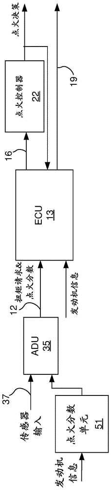
Fig. 3 provides a high-level overview of the logic of an alternative ADU-based control scheme. In this embodiment, the firing fraction unit 51 and the ADU 35 cooperate to determine a desired firing fraction that is provided to the ECU 13 along with the requested torque as represented by line 12. The ECU 13 notifies the firing controller 22 of the desired firing fraction and appropriately directs the various engine settings to operate the engine in a skip fire manner delivering the desired torque.
In the illustrated embodiment, the firing fraction unit 51 determines the firing fractions available under the current operating conditions and identifies the particular firing fractions that should be used in conjunction with the different torque requests. The firing fraction unit provides this information to the ADU along with the corresponding fuel consumption data. The ADU utilizes this fuel consumption information in determining the appropriate torque request. The desired torque is then sent to the ECU along with the associated firing fraction provided by the firing fraction unit 51.
When making skip fire based fuel economy decisions, it is important that the torque request being considered is a total torque request, rather than a simple drive torque request (which is the torque intended for the driveline). The total torque request includes any accessory torque load (e.g., load(s) imposed by an air conditioning unit, alternator, etc.). In any type of hybrid vehicle (including full hybrid, mild hybrid, mini-hybrid, micro-hybrid, etc.), it also includes any torque load (or torque boost) produced by any motor/generator(s), etc. A potential advantage of the architecture of fig. 2 is that the ECU is aware of the torque requirements of the accessories, and therefore can easily include the effects of such loads in the ignition fraction and fuel consumption determinations. When the fuel efficiency data comes from another source (e.g., the firing fraction unit 51), the ADU is generally responsible for understanding and compensating for the torque loads generated by the accessories, which tends to complicate ADU design.
While only a few specific skip fire control architectures are explicitly shown, it should be understood that the described functionality may also be implemented using a variety of other control architectures. In various embodiments, any of the ADU function, engine control function, firing fraction determination function, fuel information determination function, and ignition control function may be combined into an integrated unit, or their respective functions may be divided among multiple components, which may be integrated in any manner deemed appropriate for a particular implementation. Independent of the exact implementation architecture, accessory torque can be managed along with engine torque to optimize vehicle fuel consumption over a predicted or actual drive profile. For example, if the optimal combination of vehicle speed and firing density results in too high or too low a torque to maintain a given vehicle speed, the torque may be increased/decreased as appropriate by scheduling an alternator, hybrid motor, air conditioning system, generator, etc.
Referring next to FIG. 4, a non-exclusive method for determining a torque request based in part on skip fire related fuel economy considerations will be described. In the illustrated embodiment, the ADU 35 determines a suggested torque based on a driving schedule incorporating current and/or expected driving conditions at step 301. The complexity of the proposed torque calculation may vary greatly from embodiment to embodiment. In some embodiments, the suggested torque is largely based on the desired vehicle speed, a very simple version of which may be based on a cruise control concept. More sophisticated ADUs may utilize any sensed parameters or information available to the vehicle from an external network and/or from a nearby wirelessly connected vehicle for torque determination.
For any given torque request, as shown in step 303, a most fuel efficient firing fraction suitable for delivering the requested torque under the current operating conditions while remaining within the desired drivability constraints can be readily determined. By way of example, in the embodiment of fig. 2, the engine controller 13 is arranged to determine an operating firing fraction based on the requested torque. In the embodiment of FIG. 3, the firing fraction unit 51 determines the firing fractions that will be suitable for different levels of torque requests. Once the firing fraction and torque request are known, the associated fuel efficiency information can be readily determined. More generally, for any given operating condition (e.g., engine speed, gear, etc.), the fraction of firings and corresponding fuel consumption characteristics appropriate for any given torque request can be readily estimated.
In step 305, the ADU obtains information regarding fuel efficiency associated with different levels of torque requests. This fuel economy data may be obtained from a variety of different sources. For example, in the embodiment of FIG. 2, fuel efficiency data for different torque requests is provided by the engine controller 13. In other embodiments, the separate firing fraction calculator 51 may be arranged to identify a set of potential firing fractions and estimate their associated fuel economy characteristics, as illustrated by the embodiment of fig. 3. In other cases, the ADU may include an algorithm or may access look-up tables that estimate expected fuel consumption rates (or other suitable measures of fuel economy) at different requested torque levels based on current operating conditions (e.g., engine speed, gear, various engine settings, etc.).
In step 307, the ADU utilizes the fuel economy information to determine whether there is an alternate torque request level having an output level close to the proposed torque request that has better fuel economy than the proposed torque request. If so, the ADU determines in step 309 whether the alternative torque level is suitable for use in the current drive schedule. If the alternative, more fuel efficient torque level is deemed suitable for use, the alternative torque level is sent as a torque request, as shown in step 315. If there are no close alternative torque levels that are more fuel efficient (as determined in step 307), or if such alternative torque levels are deemed unsuitable for use under the current conditions (as determined in step 309), the proposed torque is sent to the ECU as a torque request, as shown at 311. In some cases, the torque level associated with the firing fraction may operate the engine at or near its acceptable NVH limit. Generally, the firing cylinder will operate at or near its minimum BSFC value.
It should be understood that both the threshold associated with which alternative torque levels may be worth considering and the determination of which alternative torque levels are appropriate are relative determinations that may vary greatly based on the complexity of the ADU. For example, in some embodiments, the ADU may be arranged to only look at alternative torque requests that are within a prescribed threshold range of requested torque, for example, within X% of the expected torque with enhanced fuel efficiency gain (e.g., within 1%, 2%, or 5%). Relatively small changes in torque output are generally quite acceptable, but in other situations (such as when combined with traffic conditions), changes in torque request may be less acceptable when vehicle speed begins to deviate too much from the desired ADU determined speed, or when the vehicle is moving in heavy traffic conditions. The ADU may also consider turning auxiliary loads, such as air conditioners, on or off, as described below.
In other cases, longer term planning may be involved. For example, if the connected vehicle is aware of upcoming road conditions (such as a hill, a congested area, a stop sign or red light, a change in speed limits, etc.), these variables may be incorporated into the suggested torque calculation or driving plan as appropriate. For example, if a stop or deceleration ahead is expected, the ADU may determine that the torque may be reduced earlier than it otherwise would be possible. Given one particular example, if the ADU knows that an upcoming traffic light is red within a given time window, it may have a large degree of freedom in determining a driving schedule between the current location and the traffic light, which may result in additional fuel savings. The particular torque request value utilized during this time period may be determined based on skip fire specific fuel economy information.
Further, for vehicles with regenerative braking, the braking speed and distance profile may be varied to allow for an increase in regenerative braking. For example, DCCO (deceleration fuel cut) may be input earlier. The use of skip fire in conjunction with DCCO is described in U.S. patent application No. 15/009,533, which is incorporated herein by reference. Similarly, the flexibility inherent in planning for other traffic and road conditions (including upcoming slopes, speed limit changes, traffic congestion, etc.) may lead to more fuel savings. In this way, even negative torque requests can be accommodated. By considering skip fire based fuel economy when determining the driving schedule torque request, the overall fuel efficiency of the trip may be improved.
The ADU may rely on a wide variety of different inputs from both sensors and other sources in determining its torque request. Such data may include GPS and map data that may provide a wide variety of information including the current location of the vehicle, surrounding terrain (e.g., an upcoming hill, etc.), speed limits, traffic controls such as stop signs, etc. Various sensors, such as cameras, LIDAR (light imaging, distance and ranging) and RADAR (radio detection and ranging), may provide information about surrounding vehicles and obstacles, including information about their relative velocity. The connected vehicles facilitate communication between the vehicles (e.g., vehicle-to-vehicle communication) and with the infrastructure (infrastructure-to-vehicle communication, or vice versa), which may provide a wide variety of additional information useful to the ADU, including, for example, anticipated traffic control states (e.g., traffic light timing), vehicle trajectories (e.g., changes in grade or direction), road conditions (e.g., accidents or slow traffic ahead, ice or other wet road conditions ahead, etc.), knowledge of what other vehicles are doing or will do (e.g., the vehicle ahead is about to accelerate or decelerate, switch lanes, etc.), the ability to pull or queue vehicles in tandem to reduce air resistance, etc. Any of these variables may be relevant to the determination of the driving plan. Of course, the type of information available and used in connection with the development of driving plans and/or instantaneous torque request decisions is limited only by the imagination of the ADU and the connected vehicle system designers. By knowing this type of information, the ADU can better predict expected driving behavior, which when combined with knowledge based on skip fire fuel efficiency data can help to operate the vehicle in a manner that significantly improves fuel economy. In some cases, the engine may even never be operated, for example, if the engine is off and the ADU determines that only a small crawl is required, the electric motor may be driven to supply the necessary motive force while keeping the engine off.
Referring next to fig. 5, yet another embodiment will be described. This embodiment is very similar to the embodiment of fig. 3, but is used in conjunction with a hybrid electric vehicle having an electric motor/generator that is used in conjunction with skip fire operation of an internal combustion engine. Any type of electric motor/internal combustion engine hybrid may be utilized including, but not limited to, hybrid, mild hybrid, and micro-hybrid. The advantage of the hybrid/skip fire approach is that while a fuel efficiency gain can be achieved by slightly reducing the output of the engine, the electric motor can be used to make up for the shortfall so that the entire desired output can be achieved. Thus, when the ADU 35 determines that the fuel efficiency of the engine can be improved by reducing the engine torque request, it can send a command 58 to the electric motor to add the appropriate amount of torque to the driveline to ensure that all of the desired torque is delivered. This may be particularly fuel efficient when the energy supplied by the electric motor is derived from regenerative braking or other low cost energy sources, such as plug-in power supplies or solar panels integrated in the vehicle.
In some cases, the generator function of the electric motor/generator or a separate generator may be used to reduce torque from the driveline when it is determined that fuel efficiency is higher to provide more torque than is requested at any given time. While this approach may work well in some situations, the round trip efficiency of the generator/motor and storage system must be considered when determining whether reducing torque from the driveline for power generation as a whole is more fuel efficient than simply operating at a lower requested torque level. The decision whether to reduce torque from the driveline may also take into account the current state of charge of the battery or the capacitive energy storage device.
Yet another embodiment is shown in fig. 6. This embodiment is also similar to the embodiment of fig. 3, except that the ADU exercises autonomous control over certain auxiliary device(s) 61. In practice, there may be various auxiliary devices that introduce engine load. Two of the most common load sources, which tend to involve larger loads, are alternator/generators and air conditioning units. When such devices are in use, their respective loads may increase the torque request sufficiently to require a transition to a less fuel efficient firing fraction. For example, consider an operating scenario somewhat similar to the example above, where the drive torque request is 72N × m (net) and the alternator applies an additional load of 1.5N × m, which results in a total torque request of 73.5N × m (net), as discussed in the example above. In this case, fuel consumption can be significantly improved by simply commanding the alternator to reduce its load (e.g., applying a load of 1.0N m instead of 1.5N m). When the drive torque request subsequently changes to a level that is not near the firing fraction efficiency boundary, the alternator load may be increased back to its desired level, or even to a higher level that remedies some of the shortfalls that occur during the torque reduction.
It should be appreciated that torque management may also be done in another manner in which a hybrid alternator (generator) draws power from the drive train to produce electrical energy, which may be stored in a battery or capacitor. For example, a 71N m drive torque request may be satisfied by a more fuel efficient 72N m produced by the engine, with the hybrid alternator (generator) drawing 1N m of torque for battery charging.
In many driving situations, this type of "modified" assist device control based on skip fire fuel efficiency considerations is almost undetectable to vehicle occupants.
It should also be appreciated that with some of the methods described, consumption from auxiliary devices (e.g., air conditioners or alternators) may be managed to most effectively utilize small variations in torque that improve overall fuel efficiency, i.e., the control scheme drives the load rather than the load-driven control. The ADU may determine, in a somewhat similar manner, a change in the desired engine output torque that may be needed in the near future. For example, the ADU may determine that the vehicle may be decelerating quickly and therefore requesting less engine torque, or may be approaching a hill and therefore requesting more engine torque. In these cases, the ADU may prohibit shifting or ignition density changes if the ADU determines that it is likely that the vehicle will only be operating in this new operating state for a short period of time.
Fig. 7 shows a representative drive profile associated when traveling from point a to point B. In this example, the drive profile is divided into 4 regions. Region a is the initial acceleration to speed a. Region B is nominal steady state operation at speed α. Region C is accelerated to a new higher velocity beta. Region D is nominal steady state operation at speed β. Region E is decelerated to stop at point B. Curve 720 shows an exemplary curve for a prior art autonomous control system. The vehicle smoothly accelerates and decelerates and runs at prescribed speeds α and β.
Curve 710 is an exemplary drive profile for an autonomous vehicle according to an embodiment of the present invention. In this case, the acceleration and deceleration may not coincide. The vehicle may stay at speed during acceleration or deceleration regions A, C and E, where skip fire operation of the engine provides particularly improved fuel economy. In these acceleration and deceleration regions, the maximum acceleration/deceleration may be limited to provide acceptable NVH characteristics. The rate of change of acceleration, referred to as jerk, may also be limited to provide acceptable NVH characteristics. Also, during steady state operating periods (regions B and D), the vehicle may be operating at a slightly different speed than α or β, with fuel efficiency higher than if the vehicle were operating at precise α or β. The travel time between points a and B, represented by the areas under curves 710 and 720, may be similar, meaning that operating the vehicle at a more fuel efficient ignition fraction may have little or no effect on the driving time between points a and B.
There are many examples when a driver wants to operate a vehicle at or near a speed limit at a nominally constant speed (such as open road highway driving). In a cruise control system or a prior art autonomous vehicle system, the cruise control or ADU will try to control the vehicle to this desired speed. However, the desired speed may not be consistent with the effective firing density in a skip fire controlled engine. To improve fuel economy, instead of attempting to run the vehicle at a fixed speed, cruise control or ADU may control the vehicle speed to within a desired range, such as 1mph, 2mph, or some percentage of the nominal speed 1%, 2%, etc. It should be understood that the operating range may not be symmetrical; for example, the speed change may be + 0% and-2% of a certain desired operating speed (such as a local speed limit).
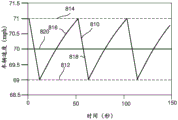
FIG. 8 shows a representative drive profile associated with controlling over a range of speeds rather than a fixed constant speed. The speed range may be based on a speed limit at which the vehicle is operating, based on towing or being towed by another vehicle, or based on some other factor. Curve 820 shows an exemplary curve for a prior art autonomous control system. In this example, the speed is controlled at a constant value of 70 mph. Vehicle speed 810 is an exemplary drive profile for an autonomous vehicle according to an embodiment of the invention. The vehicle speed 810 is allowed to vary between an upper limit 814 and a lower limit 812. In this example, the speed control is within 1mph of a nominal speed of 70mph, so the speed oscillates between 69mph and 71 mph. In this example, the period of the velocity oscillations is about 50 seconds, corresponding to a frequency of 0.02 Hz. Oscillations in this frequency range (e.g., frequencies less than about 0.5 Hz) tend to produce less undesirable NVH than the immediately adjacent frequencies above this range. Generally, vehicle acceleration and deceleration over a range of speeds may be limited to provide acceptable NVH characteristics. Likewise, the rate of change of the speed range may be limited to provide acceptable NVH characteristics.
In an acceleration portion 816 of curve 810, the engine operates at a first firing fraction, and in a deceleration portion 818, the engine operates at a second firing fraction. The second firing fraction is less than the first firing fraction and therefore generally produces insufficient torque to maintain vehicle speed, and therefore vehicle deceleration. In some cases, the second firing fraction may be zero, corresponding to a deceleration cylinder cutoff condition (DCCO) where fuel is not consumed during the portion of the drive cycle. Generally, the lower the second firing fraction, the steeper the deceleration portion 818. The first and second firing fractions may be selected to maximize fuel efficiency while maintaining acceptable NVH performance.
In some embodiments, the driver may improve fuel efficiency by selecting an economy mode or accepting a slightly lower average speed and a slightly longer travel time. That is, the driver can input the total travel time between the trip start point and the trip destination point, which is different from the travel time obtained by always limiting driving at the speed. For example, when the ADU knows and plans the entire trip, the driver may indicate to the ADU that he/she would like to accept a drive profile that takes 1, 2, or 5 minutes (or 1%, 2%, 5%) more than a drive profile that is always running at speed limit, or some other value. This flexibility may allow the ADU to operate the engine more often at a favorable effective engine displacement that improves fuel economy. Similarly, in some embodiments, the driver or ADU may accept a slightly higher NVH level, which may allow for higher efficiency firing densities and less torque converter slip to be used. Improved fuel economy may be interpreted as less total fuel being used to move the vehicle from point a to point B within some desired time.
Much of the previous description has focused on methods to improve fuel economy in an autonomously controlled vehicle that travels independently. There are also control methods that use vehicle-to-vehicle communication to improve fuel economy. One well-known method of improving fuel economy by reducing air resistance is the towing or queuing of vehicles (one or more vehicles towing each other). Under the control of the driver, such driving strategies are often dangerous due to the risk of the rear vehicle colliding with the leading vehicle in case of sudden braking of the leading vehicle. With vehicle-to-vehicle communication, this risk is greatly reduced, since the lead vehicle can communicate its brakes to all rear vehicles substantially instantaneously, and thus avoid rear-end collisions.
If one or more of the vehicles in the fleet have an engine that is capable of skip fire operation, various strategies may be used to improve the collective fuel economy of all vehicles in the fleet. For example, consider first a fleet consisting of two vehicles, one leading vehicle running at constant speed without skip fire control and the following vehicle having skip fire control. The ADU of the following vehicle can minimize fuel consumption by simultaneously considering efficiency gains from traction and those obtained by operating at a certain fuel-efficient ignition density. This may result in the following vehicle operating at an alternating firing fraction as shown with respect to fig. 8, and the distance between the lead vehicle and the following vehicle moving back and forth with the alternating firing fraction. In other cases, such an ignition density shift may not be necessary where vehicle speed coincides with fuel efficient ignition density. That is, one or both vehicles may intentionally select a speed corresponding to the fuel efficient ignition density such that the vehicles maintain a substantially constant pitch. Alternatively, if both vehicles have ADUs, they may jointly select the speed that maximizes the collective fuel efficiency. It should be appreciated that in many towing situations, the lead vehicle also experiences fuel efficiency gains, so all benefits of towing do not flow only to the trailing vehicle(s).
In the case of two vehicle queues, both of which can skip fire control, the ADUs of the two vehicles can cooperate to determine a queue speed that optimizes fuel efficiency of the overall queue. This may allow each vehicle in the fleet to operate at a sub-optimal level. Likewise, for a fleet having more than two skip fire controlled vehicles, the ADU of the vehicle may communicate between the vehicles and operate the fleet in the most fuel efficient manner.
Another embodiment of the present invention is shown in fig. 9, which depicts a non-exclusive method for controlling an autonomous vehicle. In this embodiment, an Autonomous Driving Unit (ADU) determines a recommended speed range and acceptable NVH characteristics over a time interval, as illustrated by step 901. The time interval used may vary with driving conditions. For example, when driving on an uncongested highway, the ADU may determine the recommended vehicle speed range within tens of seconds or even minutes. In contrast, in city driving or under congested conditions, the time interval may be less than one second, or even faster than the human reaction time, which is tenths of seconds. The ADU continuously evaluates whether the driving conditions have changed, as shown in step 911. If the ADU detects a change in driving conditions, control may return to step 901 where a new speed range, acceptable NVH characteristics, and time interval are determined. Changes in driving conditions may occur for a number of reasons, such as the occurrence of road hazards, stopped or slowed vehicles, pedestrians, emergency vehicles, precipitation, limited visibility, icy roads, changed stop lights, road construction, speed limit changes, and the like. It should be appreciated that if changes in driving conditions require immediate and affirmative reaction, such as emergency braking, to avoid a collision, the ADU will prioritize collision avoidance over fuel efficiency or NVH considerations and immediately react to the situation.
In step 903, the ADU determines a plurality of proposed driveline torque profiles that will propel the vehicle within the proposed speed range and that have acceptable NVH characteristics over a time interval. In step 905, fuel efficiencies for various proposed driveline torque profiles are determined. The proposed driveline torque profile may utilize different firing densities, firing fractions, or displacement levels. In some cases, the fuel efficiency of all of the proposed driveline torque profiles may be determined; however, it is possible that the ADU may determine that many torque profiles will have poor fuel efficiency without explicitly calculating its efficiency. Since these driveline torque profiles will not be used to operate the vehicle, the ADUs need not devote computing resources to determining their accurate fuel efficiency. In general, a driveline torque profile that utilizes ignition of the cylinder at or near its minimum BSFC point will maximize fuel efficiency. It should be appreciated that the firing density may vary over the time interval as long as the vehicle speed and NVH limits established in step 901 are maintained. In step 907, the recommended driveline torque profile that provides the most fuel efficient operation is selected as the operating driveline torque profile. At step 909, this operating driveline profile is used to propel the vehicle.
Although only a few embodiments of the present invention have been described in detail, it should be understood that the present invention may be embodied in many other forms without departing from the spirit or the scope of the present invention. The present invention has been described primarily in the context of applicants' engine dynamic skip fire operation wherein firing decisions are made dynamically on a firing opportunity by tracking portions of firings that have been requested but not delivered or delivered but not requested using an accumulator or other mechanism. However, the described techniques are equally applicable to managing transitions between any different skip fire fractions, or between skip fire fractions and all cylinder operation. While the invention is generally described as controlling an engine to maximize operation at a fuel efficient firing density, other factors contribute to overall vehicle efficiency. In particular, torque converter slip and transmission gear (or ratio of the continuously variable transmission) may be managed along with firing density to operate the vehicle in a manner that provides acceptable NVH performance while maximizing fuel efficiency.
Further, it should also be understood that the same principles can be applied to most any system that improves fuel consumption by changing engine displacement. This may include standard variable displacement operation of the engine, where the decision is made to transition between displacement states having different numbers of cylinders (e.g., between 4 and 8 cylinder operation or between 3, 4 and 6 cylinder operation). It may be used to switch from all cylinder operation, fixed displacement or DCCO to skip fire operation and out of skip fire operation to all cylinder operation, fixed displacement or DCCO. One such example is to transition from all cylinders operating in a 3-cylinder engine to an alternate cylinder deactivation mode in which every other cylinder is fired. It may also include multi-stage engine operation where different cylinders fire at different dynamically determined output levels (e.g., as described in U.S. patent No. 9,399,964, which is incorporated herein by reference), or fire at any other dynamic firing level modulation operating scheme. Similar techniques may also be used to manage effective displacement transitions in variable stroke engine control where the number of strokes per working cycle is varied in order to effectively vary the displacement of the engine.
In dynamic skip fire and various other dynamic firing level modulation engine control techniques, an accumulator or other mechanism may be used to track portions of requested but not delivered or delivered but not requested firings. However, the described techniques are equally applicable to engines controlled using other types of skip fire or firing level modulation techniques, including various alternate cylinder deactivation techniques. Accordingly, the present embodiments are to be considered as illustrative and not restrictive, and the invention is not to be limited to the details given herein, but may be modified within the scope and equivalents of the appended claims.