CN113684884A - Dustproof part for hinged part - Google Patents

Dustproof part for hinged part Download PDF

Info

Publication number
CN113684884A
CN113684884A CN202111170489.3A CN202111170489A CN113684884A CN 113684884 A CN113684884 A CN 113684884A CN 202111170489 A CN202111170489 A CN 202111170489A CN 113684884 A CN113684884 A CN 113684884A
Authority
CN
China
Prior art keywords
strip
dust
shaped body
groove
sealing
Prior art date
Legal status (The legal status is an assumption and is not a legal conclusion. Google has not performed a legal analysis and makes no representation as to the accuracy of the status listed.)
Pending
Application number
CN202111170489.3A
Other languages
Chinese (zh)
Inventor
李彦轩
王金华
刘菲
汤明
Current Assignee (The listed assignees may be inaccurate. Google has not performed a legal analysis and makes no representation or warranty as to the accuracy of the list.)
Ensign Heavy Industries Co ltd
Original Assignee
Ensign Heavy Industries Co ltd
Priority date (The priority date is an assumption and is not a legal conclusion. Google has not performed a legal analysis and makes no representation as to the accuracy of the date listed.)
Filing date
Publication date
Application filed by Ensign Heavy Industries Co ltd filed Critical Ensign Heavy Industries Co ltd
Priority to CN202111170489.3A priority Critical patent/CN113684884A/en
Publication of CN113684884A publication Critical patent/CN113684884A/en
Pending legal-status Critical Current

Links

Images

Classifications

    • EFIXED CONSTRUCTIONS
    • E02HYDRAULIC ENGINEERING; FOUNDATIONS; SOIL SHIFTING
    • E02FDREDGING; SOIL-SHIFTING
    • E02F9/00Component parts of dredgers or soil-shifting machines, not restricted to one of the kinds covered by groups E02F3/00 - E02F7/00
    • E02F9/006Pivot joint assemblies
    • EFIXED CONSTRUCTIONS
    • E02HYDRAULIC ENGINEERING; FOUNDATIONS; SOIL SHIFTING
    • E02FDREDGING; SOIL-SHIFTING
    • E02F9/00Component parts of dredgers or soil-shifting machines, not restricted to one of the kinds covered by groups E02F3/00 - E02F7/00
    • EFIXED CONSTRUCTIONS
    • E02HYDRAULIC ENGINEERING; FOUNDATIONS; SOIL SHIFTING
    • E02FDREDGING; SOIL-SHIFTING
    • E02F9/00Component parts of dredgers or soil-shifting machines, not restricted to one of the kinds covered by groups E02F3/00 - E02F7/00
    • E02F9/08Superstructures; Supports for superstructures
    • E02F9/0841Articulated frame, i.e. having at least one pivot point between two travelling gear units
    • FMECHANICAL ENGINEERING; LIGHTING; HEATING; WEAPONS; BLASTING
    • F16ENGINEERING ELEMENTS AND UNITS; GENERAL MEASURES FOR PRODUCING AND MAINTAINING EFFECTIVE FUNCTIONING OF MACHINES OR INSTALLATIONS; THERMAL INSULATION IN GENERAL
    • F16CSHAFTS; FLEXIBLE SHAFTS; ELEMENTS OR CRANKSHAFT MECHANISMS; ROTARY BODIES OTHER THAN GEARING ELEMENTS; BEARINGS
    • F16C11/00Pivots; Pivotal connections
    • F16C11/04Pivotal connections

Landscapes

  • Engineering & Computer Science (AREA)
  • General Engineering & Computer Science (AREA)
  • Mining & Mineral Resources (AREA)
  • Civil Engineering (AREA)
  • Structural Engineering (AREA)
  • Mechanical Engineering (AREA)
  • Sealing Devices (AREA)

Abstract

本发明公开一种铰接部位防尘件,包括柔性条带状本体,该条带状本体的下表面上具有第一凹槽,且该第一凹槽沿着条带状本体的下表面长度方向分布。所述条带状本体的上表面上沿着其长度方向具有条状密封部,所述密封部的上端端部为分叉状结构,且形成的叉口沿着所述条带状本体的长度方向分布。本发明的防尘件为条带状结构,可根据需要的长度切割,使用和更换方便快捷,避免了传统的环形密封圈更换时要拆除销轴,导致费时费力的问题。另外,该防尘件具有端部为分叉状结构的密封件,其和条带状本体分别实现对铰接部位径向、轴向方向上的双重防尘密封,可有效防止灰尘、沙粒进入铰接部位内部结构,提高轴、套的使用寿命,提升整机可靠性。

Figure 202111170489

The invention discloses a hinged part dustproof piece, comprising a flexible strip-shaped body, the lower surface of the strip-shaped body is provided with a first groove, and the first groove is along the length direction of the lower surface of the strip-shaped body distributed. The upper surface of the strip-shaped body is provided with a strip-shaped sealing part along the length direction thereof, the upper end of the sealing part is a bifurcated structure, and the formed fork is along the length of the strip-shaped body directional distribution. The dustproof element of the present invention is a strip-shaped structure, which can be cut according to the required length, and is convenient and quick to use and replace, and avoids the problem of time-consuming and labor-intensive problems caused by removing the pin shaft when replacing the traditional annular sealing ring. In addition, the dust-proof member has a sealing member with a bifurcated structure at the end, which and the strip-shaped body respectively realize double dust-proof sealing of the hinge part in the radial and axial directions, which can effectively prevent dust and sand from entering. The internal structure of the hinged part improves the service life of the shaft and the sleeve and improves the reliability of the whole machine.

Figure 202111170489

Description

Dustproof part for hinged part
Technical Field
The invention relates to the technical field of dustproof parts, in particular to a dustproof part for a hinge part.
Background
The information disclosed in this background of the invention is only for enhancement of understanding of the general background of the invention and is not necessarily to be taken as an acknowledgement or any form of suggestion that this information forms the prior art already known to a person skilled in the art.
The loader is mainly used for loading and unloading bulk materials, and the working device is used as an actuating element of the loader, and the successful operation of the working device is a necessary condition for realizing shovel loading. The structure style and the performance of the dustproof piece at the corresponding hinge part are good and bad, and the operation reliability of the loader is directly influenced. Original dust ring is rubber ring shape closed, through with both sides contact surface closedown seal to scraper bowl articulated position is the example, and it rotates frequently and often is covered by the material, and rubber dust ring receives environmental impact big, and easy wearing and tearing become invalid, the bloated big deformation, and the dustproof performance is poor, makes small dirt particle get into inside the dust ring easily, and the wearing and tearing axle sleeve causes the structure abnormal sound even, will demolish the round pin axle when changing the dust ring moreover and waste time and energy.
Disclosure of Invention
Aiming at the problems, the invention provides the dustproof piece for the hinged part, and the dustproof ring has the characteristics of good dustproof effect and convenience in replacement, and is beneficial to better improving the working performance of the hinged part and prolonging the service life of a shaft and a sleeve. In order to achieve the above object, the technical solution of the present invention is as follows.
A hinge site dust guard comprising: the flexible strip-shaped body is provided with a first groove on the lower surface, and the first groove is distributed along the length direction of the lower surface of the strip-shaped body. The upper surface of the strip-shaped body is provided with a strip-shaped sealing part along the length direction, the upper end part of the sealing part is of a forked structure, and formed strip-shaped fork openings are distributed along the length direction of the strip-shaped body.
Further, the end shape of the sealing portion includes any one of "U" branch, "Y" branch, "V" branch, "W" branch, "C" branch, "K" branch, and the like.
Further, the upper surface of the strip-shaped body is provided with second grooves which are distributed along the length direction of the strip-shaped body, and one side or two sides of the sealing part are distributed with second grooves.
Further, a third groove is formed between the root of the sealing part and the upper surface of the strip-shaped body, and the third groove is distributed along the length direction of the strip-shaped body.
Furthermore, the dustproof piece at the hinge part is made of any one of rubber and polyurethane, preferably polyurethane, and has the advantages of oil resistance, wear resistance and aging resistance.
Further, a binding member for fixing the hinge portion dust-proof to the mounting member thereof is further included, and in this state, the binding member is located in the first groove.
Further, the binding member includes any one of a snap ring, a clip, a binding wire, and the like, and since the dust-proof member at the hinge portion has a strip-shaped structure and can be cut according to a desired length, it is necessary to fix the dust-proof ring to the mounting member thereof by means of another member when in use.
Further, the hinge portion has a fourth groove in which a strip seal portion of the strip-shaped body is pressed in a sealed state.
Compared with the prior art, the invention has the following beneficial effects:
(1) the dustproof piece at the hinged part is of a strip-shaped structure, can be cut according to the required length, is convenient and quick to use and replace, and solves the problem that time and labor are wasted due to the fact that a pin shaft needs to be detached when a traditional annular sealing ring is replaced.
(2) The hinge part dustproof piece disclosed by the invention is provided with the sealing piece with the end part in a forked structure, and the sealing piece and the strip-shaped body respectively realize double dustproof sealing in the radial direction and the axial direction of the hinge part, so that dust and sand can be effectively prevented from entering the internal structure of the hinge part, the service life of a shaft and a sleeve is prolonged, and the reliability of the whole machine is improved.
Drawings
The accompanying drawings, which are incorporated in and constitute a part of this specification, are included to provide a further understanding of the invention, and are incorporated in and constitute a part of this specification, illustrate exemplary embodiments of the invention and together with the description serve to explain the invention and not to limit the invention.
Fig. 1 is a schematic structural view of a dust-proof member of a hinge portion according to an embodiment of the present invention.
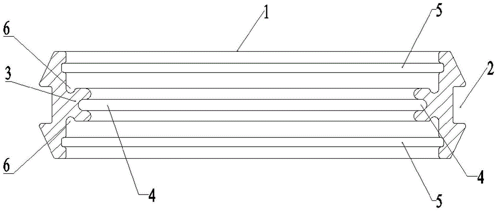
Fig. 2 is a cross-sectional view of a hinge portion dust guard in an embodiment of the invention.
Fig. 3 is a sectional view showing a usage state of the dust-proof member at the hinge portion according to the embodiment of the present invention.
The labels in the figures represent: 1-strip-shaped body, 2-first groove, 3-sealing part, 4-strip-shaped fork mouth, 5-second groove, 6-third groove, 7-fourth groove, 8-first hinge part and 9-second hinge part.
Detailed Description
It is to be understood that the following detailed description is exemplary and is intended to provide further explanation of the invention as claimed. Unless defined otherwise, all technical and scientific terms used herein have the same meaning as commonly understood by one of ordinary skill in the art to which this invention belongs.
For convenience of description, the words "up", "down", "left" and "right" in the present invention, if any, merely indicate that the directions of movement are consistent with those of the drawings, and do not limit the structure, but merely facilitate the description of the invention and simplify the description, rather than indicate or imply that the referenced device or element needs to have a particular orientation, be constructed and operated in a particular orientation, and thus should not be construed as limiting the invention. The description will be further described with reference to the drawings and specific examples.
Referring to fig. 1 and 2, a hinge portion dust-proof member is illustrated, which includes a strip-shaped body 1 made of a flexible material, the strip-shaped body 1 is vertically disposed, and has a first groove 2 on an outer surface thereof, and the first groove 2 is distributed along a length direction of the outer surface of the strip-shaped body 1, and the main function of the dust-proof member is to facilitate accommodating a binding member when the hinge portion is sealed by using the dust-proof member, and the binding member is placed in the first groove 2 to facilitate fixing of the dust-proof member and prevent the dust-proof member and the binding member from falling off. The binding component can adopt a clamping ring or a clamping hoop. Since the dustproof member of the hinge part of the present invention is a strip-shaped structure, it can be cut according to the required length, so that the dustproof ring needs to be fixed on the installation part by other parts when in use. Meanwhile, the strip-shaped dustproof piece can be cut according to the required length, so that the dustproof piece is convenient and quick to use and replace, and the problem that the pin shaft is required to be detached when the traditional annular sealing ring is replaced, and time and labor are wasted is solved.
The inner surface of the strip-shaped body 1 is provided with strip-shaped sealing parts 3 along the length direction, the end parts of the sealing parts 3 are of a forked structure, and strip-shaped fork openings 4 are formed and distributed along the length direction of the strip-shaped body 1. Referring to fig. 3, the sealing part 3 of the bifurcated structure mainly functions to be squeezed in the fourth groove 7 between the first hinge part 8 and the second hinge part 9 to be sealed, so that the hinge part is radially sealed, and the dustproof effect is improved. And the bifurcation can make sealing part 3 more easily extruded and get into fourth recess 7 at sealed in-process, and the bifurcation position of extrusion back sealing part 3 has the trend that the bullet opened and resets, consequently can support tightly at the upper and lower surface of fourth recess 7, makes dustproof effect better. Based on this, it should be understood that the end shape of the sealing portion 3 may be selected from any one of the shapes including, but not limited to, "U" -shaped branch, "Y" -shaped branch, "V" -shaped branch, "W" -shaped branch, "C" -shaped branch, "K" -shaped branch, and the like. It should be noted that the sealing portion 3 having simple modifications, replacements, and the like similar to the above technical idea is included in the scope of the present invention.
With continued reference to fig. 2, in another preferred embodiment, the strip-shaped body 1 has second grooves 5 on its upper surface, the second grooves 5 are distributed along the length direction of the strip-shaped body 1, and the second grooves 5 are distributed on one side or both sides of the sealing part 3. The main function of the second groove 5 is to improve the radial sealing effect and the dirt holding capacity.
With continued reference to figure 2, in another preferred embodiment, between the root of said seal 3 and the upper surface of the strip-like body 1 there are third grooves 6, the third grooves 6 being distributed along the length of the strip-like body 1. The main function of the third groove 6 is to improve the axial sealing effect and the dirt holding capacity.
In another preferred embodiment, the material of the dust-proof part at the hinge part is selected from polyurethane, and compared with a rubber material, the polyurethane has better oil resistance, wear resistance and aging resistance, and is beneficial to prolonging the service life of the dust-proof part.
Finally, it should be understood that any modification, equivalent replacement, or improvement made within the spirit and principle of the present invention should be included in the protection scope of the present invention. Although the embodiments of the present invention have been described with reference to the accompanying drawings, it is not intended to limit the scope of the present invention, and it should be understood by those skilled in the art that various modifications and variations can be made without inventive efforts by those skilled in the art based on the technical solution of the present invention.

Claims (9)

1. A hinge portion dust guard, comprising: the flexible strip-shaped body is provided with a strip-shaped sealing part on the upper surface along the length direction of the flexible strip-shaped body, the upper end part of the sealing part is of a forked structure, and strip-shaped fork openings formed by the sealing part are distributed along the length direction of the flexible strip-shaped body.
2. The hinge region dust seal of claim 1, wherein the end shape of the seal portion includes any one of a "U" branch, a "Y" branch, a "V" branch, a "W" branch, a "C" branch, and a "K" branch.
3. The hinge portion dust-proof member according to claim 1, wherein the strip-shaped body has a first groove on a lower surface thereof, and the first groove is distributed along a length of the lower surface of the strip-shaped body.
4. The hinge portion dust-proof member of claim 1, wherein the strip body has second grooves formed on an upper surface thereof, the second grooves being formed along a length direction of the strip body, and the second grooves being formed on one side or both sides of the sealing portion.
5. The hinge portion dust-proof member according to claim 1, wherein a third groove is formed between the root portion of the sealing portion and the upper surface of the strip body, the third groove being formed along the length of the strip body.
6. The hinge portion dust-proof member according to claim 1, wherein the material of the hinge portion dust-proof member includes any one of rubber and polyurethane.
7. The hinge region dust seal of any one of claims 1-6 further comprising a binding member positioned in the first recess and securing the hinge region dust seal to its mounting member.
8. The hinge portion dust-proof of claim 7, wherein the binding member comprises any one of a snap ring, a clip, and a binding wire.
9. Hinge site dust protection according to claim 1, wherein the hinge site has a fourth groove in which the sealing part is pressed in the sealed state.
CN202111170489.3A 2021-10-08 2021-10-08 Dustproof part for hinged part Pending CN113684884A (en)

Priority Applications (1)

Application Number Priority Date Filing Date Title
CN202111170489.3A CN113684884A (en) 2021-10-08 2021-10-08 Dustproof part for hinged part

Applications Claiming Priority (1)

Application Number Priority Date Filing Date Title
CN202111170489.3A CN113684884A (en) 2021-10-08 2021-10-08 Dustproof part for hinged part

Publications (1)

Publication Number Publication Date
CN113684884A true CN113684884A (en) 2021-11-23

Family

ID=78587698

Family Applications (1)

Application Number Title Priority Date Filing Date
CN202111170489.3A Pending CN113684884A (en) 2021-10-08 2021-10-08 Dustproof part for hinged part

Country Status (1)

Country Link
CN (1) CN113684884A (en)

Citations (10)

* Cited by examiner, † Cited by third party
Publication number Priority date Publication date Assignee Title
US6471211B1 (en) * 2000-08-28 2002-10-29 Brenco, Incorporated Seal assembly
US9132539B1 (en) * 2014-06-06 2015-09-15 Aktiebolaget Skf Method of forming a V-ring seal
CN206309966U (en) * 2016-12-21 2017-07-07 苏州艾尔泰流体控制有限公司 A kind of butterfly valve seal circle and butterfly valve
CN206972646U (en) * 2017-06-23 2018-02-06 北京金自天成液压技术有限责任公司 A kind of extension type ripple dust ring and a kind of fine setting hydraulic cylinder
CN208189675U (en) * 2018-04-27 2018-12-04 天津市捷威动力工业有限公司 A kind of Battery case gasket
CN112117588A (en) * 2020-09-29 2020-12-22 宣城立讯精密工业有限公司 A sealing ring and connector
CN112747005A (en) * 2020-12-10 2021-05-04 唯万科技有限公司 Pump truck main oil cylinder piston rod sealing system
CN213628845U (en) * 2020-11-13 2021-07-06 飞荣达科技(江苏)有限公司 Y-shaped sealing strip for inflation die
CN214092520U (en) * 2020-11-04 2021-08-31 河北奥赛罗密封材料有限公司 Piston rod sealing ring with waterproof and dustproof functions
CN215715675U (en) * 2021-10-08 2022-02-01 英轩重工有限公司 Dustproof part for hinged part

Patent Citations (10)

* Cited by examiner, † Cited by third party
Publication number Priority date Publication date Assignee Title
US6471211B1 (en) * 2000-08-28 2002-10-29 Brenco, Incorporated Seal assembly
US9132539B1 (en) * 2014-06-06 2015-09-15 Aktiebolaget Skf Method of forming a V-ring seal
CN206309966U (en) * 2016-12-21 2017-07-07 苏州艾尔泰流体控制有限公司 A kind of butterfly valve seal circle and butterfly valve
CN206972646U (en) * 2017-06-23 2018-02-06 北京金自天成液压技术有限责任公司 A kind of extension type ripple dust ring and a kind of fine setting hydraulic cylinder
CN208189675U (en) * 2018-04-27 2018-12-04 天津市捷威动力工业有限公司 A kind of Battery case gasket
CN112117588A (en) * 2020-09-29 2020-12-22 宣城立讯精密工业有限公司 A sealing ring and connector
CN214092520U (en) * 2020-11-04 2021-08-31 河北奥赛罗密封材料有限公司 Piston rod sealing ring with waterproof and dustproof functions
CN213628845U (en) * 2020-11-13 2021-07-06 飞荣达科技(江苏)有限公司 Y-shaped sealing strip for inflation die
CN112747005A (en) * 2020-12-10 2021-05-04 唯万科技有限公司 Pump truck main oil cylinder piston rod sealing system
CN215715675U (en) * 2021-10-08 2022-02-01 英轩重工有限公司 Dustproof part for hinged part

Similar Documents

Publication Publication Date Title
CN215715675U (en) Dustproof part for hinged part
US20110227355A1 (en) Severe duty grapple with tubular pivot
JPH10230720A (en) Track link assembly body having pin holder
JP2009506278A (en) Dust boot with grease relief passage
JP5146646B2 (en) Dust cover fixing structure
CN113684884A (en) Dustproof part for hinged part
US9140365B1 (en) Outer seal
JP4949335B2 (en) Rubber cushioning member and bucket cylinder
JP4372086B2 (en) Bearing bush
JP4805237B2 (en) Seal member
JP2005003150A (en) Bearing section seal of construction machinery
US8240945B2 (en) Axisymmetric parts equipped with dust removal grooves
JPH09303569A (en) Lip type seal
JPH10122378A (en) Bearing device
CN221462740U (en) Dustproof automobile ball head
CN219605855U (en) Bearing seal ring with good dustproof effect
CN218454960U (en) Novel sealing ring
KR200299030Y1 (en) Sealing device of power steering piston for automobile
CN221503781U (en) A wear-resistant loader boom sleeve
CN221880224U (en) A transmission shaft oil seal
JPH11125336A (en) Rubber gasket and molding die therefor
CN217177008U (en) Hydraulic multi-way valve assembly with valve sleeve
JP5153897B2 (en) Seal member
KR200379309Y1 (en) Seal for protecting spatter
KR102771816B1 (en) Snap Ring having an elastic force in the axial direction

Legal Events

Date Code Title Description
PB01 Publication
PB01 Publication
SE01 Entry into force of request for substantive examination
RJ01 Rejection of invention patent application after publication

Application publication date: 20211123

RJ01 Rejection of invention patent application after publication