CN113682984A - A mountain balance crane - Google Patents

A mountain balance crane Download PDF

Info

Publication number
CN113682984A
CN113682984A CN202111008666.8A CN202111008666A CN113682984A CN 113682984 A CN113682984 A CN 113682984A CN 202111008666 A CN202111008666 A CN 202111008666A CN 113682984 A CN113682984 A CN 113682984A
Authority
CN
China
Prior art keywords
hydraulic telescopic
telescopic rod
mountain
rod
telescoping rod
Prior art date
Legal status (The legal status is an assumption and is not a legal conclusion. Google has not performed a legal analysis and makes no representation as to the accuracy of the status listed.)
Granted
Application number
CN202111008666.8A
Other languages
Chinese (zh)
Other versions
CN113682984B (en
Inventor
张德宝
Current Assignee (The listed assignees may be inaccurate. Google has not performed a legal analysis and makes no representation or warranty as to the accuracy of the list.)
Nanjing Iot And Ic Design Industry Innovation Center Co ltd
Original Assignee
Individual
Priority date (The priority date is an assumption and is not a legal conclusion. Google has not performed a legal analysis and makes no representation as to the accuracy of the date listed.)
Filing date
Publication date
Application filed by Individual filed Critical Individual
Priority to CN202111008666.8A priority Critical patent/CN113682984B/en
Publication of CN113682984A publication Critical patent/CN113682984A/en
Application granted granted Critical
Publication of CN113682984B publication Critical patent/CN113682984B/en
Active legal-status Critical Current
Anticipated expiration legal-status Critical

Links

Images

Classifications

    • BPERFORMING OPERATIONS; TRANSPORTING
    • B66HOISTING; LIFTING; HAULING
    • B66CCRANES; LOAD-ENGAGING ELEMENTS OR DEVICES FOR CRANES, CAPSTANS, WINCHES, OR TACKLES
    • B66C23/00Cranes comprising essentially a beam, boom, or triangular structure acting as a cantilever and mounted for translatory of swinging movements in vertical or horizontal planes or a combination of such movements, e.g. jib-cranes, derricks, tower cranes
    • B66C23/62Constructional features or details
    • B66C23/72Counterweights or supports for balancing lifting couples
    • B66C23/78Supports, e.g. outriggers, for mobile cranes
    • B66C23/80Supports, e.g. outriggers, for mobile cranes hydraulically actuated
    • BPERFORMING OPERATIONS; TRANSPORTING
    • B66HOISTING; LIFTING; HAULING
    • B66CCRANES; LOAD-ENGAGING ELEMENTS OR DEVICES FOR CRANES, CAPSTANS, WINCHES, OR TACKLES
    • B66C23/00Cranes comprising essentially a beam, boom, or triangular structure acting as a cantilever and mounted for translatory of swinging movements in vertical or horizontal planes or a combination of such movements, e.g. jib-cranes, derricks, tower cranes
    • B66C23/88Safety gear

Landscapes

  • Engineering & Computer Science (AREA)
  • Mechanical Engineering (AREA)
  • Jib Cranes (AREA)

Abstract

本发明公开了一种山地平衡起吊车,包括履带行走架,两个所述履带行走架的内侧相对固接有基板,两个所述基板的顶部前后两端均分别设置有前液压伸缩杆和后液压伸缩杆,所述前液压伸缩杆和后液压伸缩杆的动杆外壁均固接有托板,所述托板的顶部转动连接有操作基台。该山地平衡起吊车,通过将操作室、起吊力臂等设置在操作基台上,然后通过前液压伸缩杆和后液压伸缩杆带动操作基台调整倾斜角度,保证了操作室和起吊力臂始终可以保持水平或接近水平状态,从而保证了操作人员可以稳定的操作设备,同时,起吊力臂不会因为山地的坡度问题无法将打塔人员送至准确的打塔位置。

Figure 202111008666

The invention discloses a mountain balance hoist, comprising a crawler walking frame, a base plate is relatively fixedly connected to the inner side of the two crawler walking frames, and front hydraulic telescopic rods and a front hydraulic telescopic rod and a front hydraulic telescopic rod and The rear hydraulic telescopic rod, the outer walls of the movable rods of the front hydraulic telescopic rod and the rear hydraulic telescopic rod are fixedly connected with a support plate, and the top of the support plate is rotatably connected with an operating base. The mountain balance hoist, by setting the operating room and the lifting arm on the operating base, and then driving the operating base to adjust the inclination angle through the front hydraulic telescopic rod and the rear hydraulic telescopic rod, ensures that the operating room and the lifting arm are always It can be maintained in a horizontal or near-level state, thus ensuring that the operator can operate the equipment stably, and at the same time, the lifting arm will not be unable to send the tower striker to the exact tower strike position due to the slope of the mountain.

Figure 202111008666

Description

Mountain land balance crane
Technical Field
The invention relates to the technical field of cranes, in particular to a mountain balance crane.
Background
Pine nuts are one of the common nuts, which grow within the pine cone on the tip of the pine tree. The process of taking the pine cones is called as 'digging the towers', and the former digging the towers needs to be done on the crown with a high height. The top branches are thin and long, so that the weight of a tower crane cannot be borne, the tower crane is very difficult and dangerous, and the efficiency is low.
Based on this, the current tower-digging work is often assisted by various climbing equipment. Among them, a crane is used as a frequent equipment. However, many pine trees grow in mountains or hilly lands, and due to the fact that the growing environment has a large slope, when the operation is performed in a tower digging process, the operation plane is often not a horizontal plane, so that the operator cannot keep a proper operation position, and even the operator is in danger of overturning due to gravity center deviation. Meanwhile, due to the existence of the gradient, the conventional common crane cannot conveniently, smoothly and accurately convey tower beating personnel to a proper tower beating position.
Disclosure of Invention
The present invention has been made to solve the above-mentioned problems occurring in the prior art.
In order to achieve the purpose, the invention provides the following technical scheme: the utility model provides a balanced crane that plays of mountain region, includes track walking frame, two the inboard rigid coupling base plate of track walking frame, two hydraulic telescoping rod and back hydraulic telescoping rod before both ends are equallyd divide and do not are provided with around the top of base plate, the equal rigid coupling of moving outer wall of preceding hydraulic telescoping rod and back hydraulic telescoping rod has the layer board, the top of layer board is rotated and is connected with the operation base station.
Preferably, the two front hydraulic telescopic rods are fixedly connected through a cross beam, and the two rear hydraulic telescopic rods are fixedly connected through a cross beam.
Preferably, the front hydraulic telescopic rod and the rear hydraulic telescopic rod are connected through a connecting beam, and the connecting beam is connected with the front hydraulic telescopic rod and the rear hydraulic telescopic rod in a rotating mode.
Preferably, a horizontal sensor is arranged at the bottom of the operating platform.
Preferably, two the rear side outer wall of back hydraulic telescoping rod all rotates and is connected with the regulation telescopic link, and adjusts the telescopic link and rotate with the operation panel and be connected.
Compared with the prior art, the invention has the beneficial effects that: this balanced crane that rises in mountain region through with the control chamber, the lifting arm of force etc. sets up on the operation base station, then drives operation base station adjustment inclination through preceding hydraulic telescoping rod and back hydraulic telescoping rod, has guaranteed that the control chamber can keep the level or be close the horizontality with the lifting arm of force all the time to guaranteed the operating equipment that operating personnel can be stable, simultaneously, the lifting arm of force also can not be because the slope problem in mountain region can't will beat the tower personnel and send to the accurate position of beating the tower.
Drawings
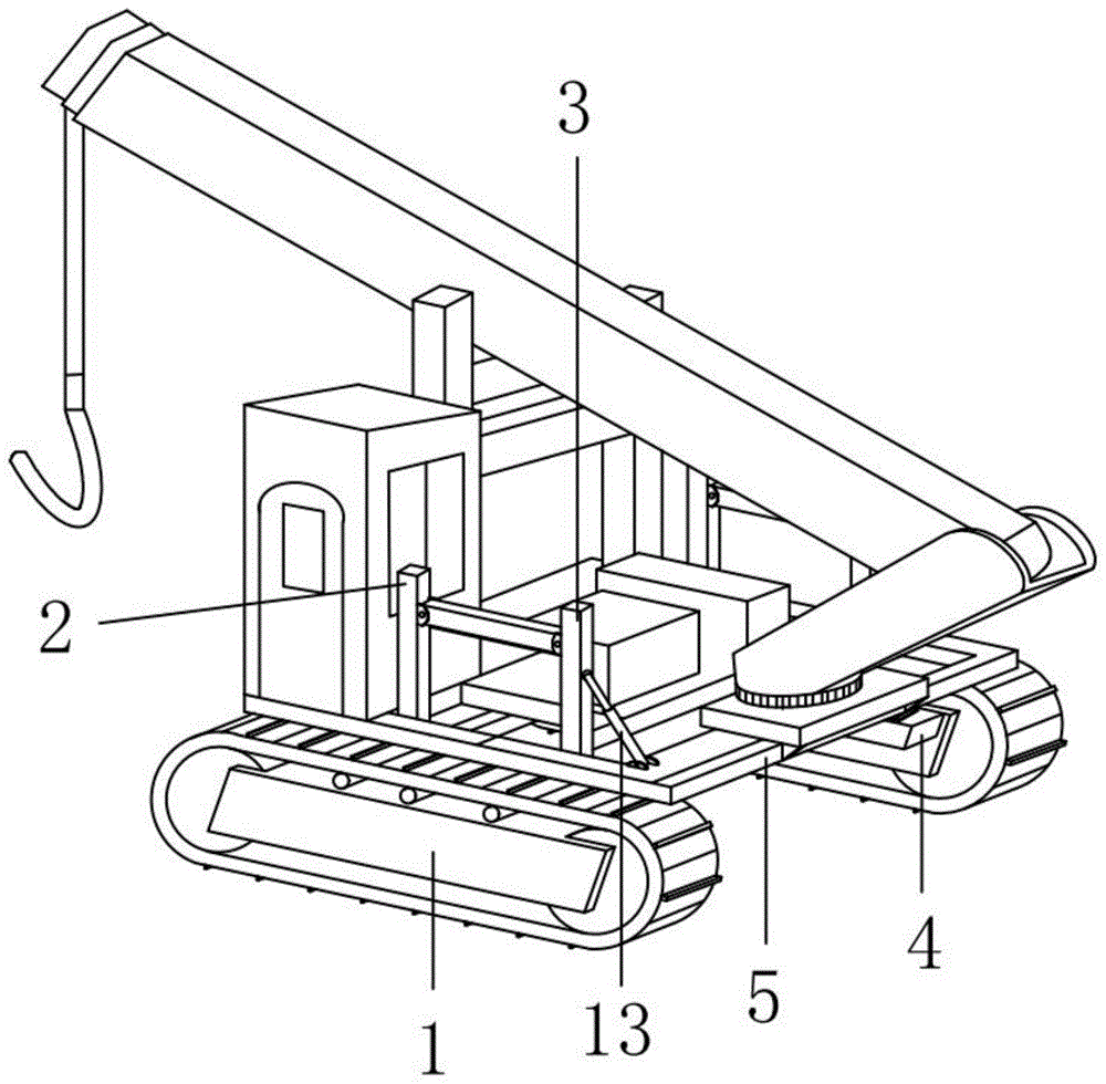
FIG. 1 is a schematic perspective view of a preferred embodiment of the present invention;
FIG. 2 is a schematic bottom view of the operating platform according to a preferred embodiment of the present invention;
FIG. 3 is a schematic perspective view of a connection relationship between a front hydraulic telescopic rod and a rear hydraulic telescopic rod according to a preferred embodiment of the present invention;
fig. 4 is a schematic perspective view of a substrate according to a preferred embodiment of the present invention.
In the figure: 1. crawler walking frame, 2, preceding hydraulic telescoping rod, 3, preceding hydraulic telescoping rod, 4, base plate, 5, operation base station, 6, opening, 7, first roating seat, 8, tie-beam, 9, layer board, 10, second roating seat, 11, crossbeam, 12, recess, 13, adjust the telescopic link.
Detailed Description
The technical solutions in the embodiments of the present invention will be clearly and completely described below with reference to the drawings in the embodiments of the present invention, and it is obvious that the described embodiments are only a part of the embodiments of the present invention, and not all of the embodiments. All other embodiments, which can be derived by a person skilled in the art from the embodiments given herein without making any creative effort, shall fall within the protection scope of the present invention.
Referring to fig. 1, a mountain region balance crane, including track walking frame 1, two track walking frame 1's inboard rigid couplings have the base plate 4 that is used for supporting preceding hydraulic telescoping rod 2 and back hydraulic telescoping rod 3, both ends are provided with preceding hydraulic telescoping rod 2 and the back hydraulic telescoping rod 3 that supports operation base station 5 and play the regulation balance effect respectively around every base plate 4's the top, operation base station 5 sets up in the front hydraulic telescoping rod 2 and the periphery of back hydraulic telescoping rod 3, and preceding hydraulic telescoping rod 2 all runs through operation base station 5 through opening 6 with back hydraulic telescoping rod 3, the bottom of operation panel 5 sets up level sensor. When the operation platform is inclined, the horizontal sensor can detect the horizontal state of the operation platform, and a signal can be sent back to the operation platform when the operation platform is inclined. An operator operates the hydraulic control rod positioned in the operating platform according to the feedback model, and the horizontal position of the operating platform is changed through the front and rear hydraulic telescopic rods.
The outer wall of two back hydraulic telescoping rod 3 all rotates and is connected with regulation telescopic link 13, and adjusts telescopic link 13 and rotate with operation panel 5 and be connected. And the adjusting telescopic rod 13 connected with the control system is used for controlling the front-back inclination angle of the back hydraulic telescopic rod 3. The situation that the front hydraulic telescopic rod 2 drives the rear hydraulic telescopic rod 3 to rotate and incline due to gravity is avoided.
Referring to fig. 2, two through holes 6 are formed on the surface of the operating base 5, and the front hydraulic telescopic rod 2 and the rear hydraulic telescopic rod 3 pass through the through holes 6. The edge of the through opening 6 is provided with a first rotating seat 7. The first rotary base 7 can be placed inside the second rotary base 10 on the top of the supporting plate 9, and the first rotary base 7 and the second rotary base 10 are connected together through a pin shaft. The top of the operation base 5 can be placed with an operation room, a boom, an engine, a hydraulic cylinder and the like.
Referring to fig. 3, the front hydraulic telescopic rod 2 and the rear hydraulic telescopic rod 3 are connected with a hydraulic cylinder, and the hydraulic cylinder is controlled by an operation room. The two front hydraulic telescopic rods 2 work synchronously and are fixedly connected through a cross beam 11; two back hydraulic telescoping rod 3 synchronous working, through crossbeam 11 fixed connection. Preceding hydraulic telescoping rod 2 is connected through tie-beam 8 with back hydraulic telescoping rod 3 between, and tie-beam 8 all rotates with preceding hydraulic telescoping rod 2 and back hydraulic telescoping rod 3 to be connected, and tie-beam 8 plays certain firm effect. The outer walls of the moving rods of the front hydraulic telescopic rod 2 and the rear hydraulic telescopic rod 3 are fixedly connected with supporting plates 9, and the supporting plates 9 are used for supporting and connecting the operation base station 5. The moving rods of the front hydraulic telescopic rod 2 and the rear hydraulic telescopic rod 3 drive the supporting plate 9 when moving, so that the operation base station 5 on one side is driven to move.
Referring to fig. 4, a groove 12 is formed on the top surface of the base plate 4, and a pin insertion hole is formed in one side of the base plate 4. One end of the fixed rod of the front hydraulic telescopic rod 2 and one end of the fixed rod of the rear hydraulic telescopic rod 3 are inserted into the inner side of the groove 12. The pin shaft is inserted into the pin shaft insertion hole to sequentially penetrate through the base plate 4 and the front hydraulic telescopic rod 2 or the rear hydraulic telescopic rod 3. The rotary connection within a certain range is realized.
After the crane runs on a hillside, when the running direction is above the slope, the two rear hydraulic telescopic rods 3 are controlled to work, and the movable rods of the rear hydraulic telescopic rods 3 drive the rear operation base station 5 to rise upwards. Through 3 extensions of back hydraulic telescoping rod, and the length of tie-beam 8 is unchangeable, preceding hydraulic telescoping rod 2 is motionless, along with 8 both ends of tie-beam with preceding hydraulic telescoping rod 2 and back hydraulic telescoping rod 3 rotate, pull 3 tops of back hydraulic telescoping rod and be close to forward hydraulic telescoping rod 2, guarantee that the focus of crane remains throughout between the walking frame, avoid the phenomenon of overturning. And conversely, when the head of the tail of the crane above the slope is below the slope, the front hydraulic telescopic rod 2 is controlled to be lifted upwards.
In the description of the present invention, it is to be understood that the terms "surface", "bottom", "one end", "top", "right and left sides", "the other end", "upper", "one side", "top", "inner", "front", "center", "both ends", and the like indicate orientations or positional relationships based on those shown in the drawings, and are only for convenience of description and simplicity of description, and do not indicate or imply that the device or element referred to must have a particular orientation, be constructed in a particular orientation, and be operated, and thus, are not to be construed as limiting the present invention.
Furthermore, the terms "first", "second" are used for descriptive purposes only and are not to be construed as indicating or implying a relative importance or implicitly indicating the number of technical features indicated, whereby a feature defined as "first", "second" may explicitly or implicitly include at least one such feature.
In the present invention, unless otherwise expressly specified or limited, the terms "mounted," "disposed," "connected," "secured," "screwed" and the like are to be construed broadly, e.g., as meaning fixedly connected, detachably connected, or integrally formed; can be mechanically or electrically connected; the terms may be directly connected or indirectly connected through an intermediate, and may be communication between two elements or interaction relationship between two elements, unless otherwise specifically limited, and the specific meaning of the terms in the present invention will be understood by those skilled in the art according to specific situations.
Although embodiments of the present invention have been shown and described, it will be appreciated by those skilled in the art that changes, modifications, substitutions and alterations can be made in these embodiments without departing from the principles and spirit of the invention, the scope of which is defined in the appended claims and their equivalents.

Claims (5)

1. The utility model provides a balanced crane that rises of mountain region, includes track walking frame (1), its characterized in that: two the relative rigid coupling in inboard of track walking frame (1) has base plate (4), two hydraulic telescoping rod (2) and back hydraulic telescoping rod (3) before both ends are equallyd divide around the top of base plate (4) do not being provided with, the equal rigid coupling of moving the outer wall of pole of preceding hydraulic telescoping rod (2) and back hydraulic telescoping rod (3) has layer board (9), the top of layer board (9) is rotated and is connected with operation base station (5).
2. The mountain balance hoist crane of claim 1, wherein: the two front hydraulic telescopic rods (2) are fixedly connected through a cross beam (11), and the two rear hydraulic telescopic rods (3) are fixedly connected through a cross beam (11).
3. The mountain balance hoist crane of claim 1, wherein: the front hydraulic telescopic rod (2) is connected with the rear hydraulic telescopic rod (3) through a connecting beam (8), and the connecting beam (8) is connected with the front hydraulic telescopic rod (2) and the rear hydraulic telescopic rod (3) in a rotating mode.
4. The mountain balance hoist crane of claim 1, wherein: and a horizontal sensor is arranged at the bottom of the operating platform (5).
5. The mountain balance hoist crane of claim 1, wherein: two the rear side outer wall of back hydraulic telescoping rod (3) all rotates and is connected with regulation telescopic link (13), and adjusts telescopic link (13) and rotate with operation panel (5) and be connected.
CN202111008666.8A 2021-08-31 2021-08-31 Mountain balance lifting crane Active CN113682984B (en)

Priority Applications (1)

Application Number Priority Date Filing Date Title
CN202111008666.8A CN113682984B (en) 2021-08-31 2021-08-31 Mountain balance lifting crane

Applications Claiming Priority (1)

Application Number Priority Date Filing Date Title
CN202111008666.8A CN113682984B (en) 2021-08-31 2021-08-31 Mountain balance lifting crane

Publications (2)

Publication Number Publication Date
CN113682984A true CN113682984A (en) 2021-11-23
CN113682984B CN113682984B (en) 2024-10-29

Family

ID=78584120

Family Applications (1)

Application Number Title Priority Date Filing Date
CN202111008666.8A Active CN113682984B (en) 2021-08-31 2021-08-31 Mountain balance lifting crane

Country Status (1)

Country Link
CN (1) CN113682984B (en)

Citations (8)

* Cited by examiner, † Cited by third party
Publication number Priority date Publication date Assignee Title
KR200417187Y1 (en) * 2006-02-22 2006-05-24 대한민국 Track-type Compact Land Truck
CN103613009A (en) * 2013-12-02 2014-03-05 安涛(宁波)电器有限公司 A crawler crane
CN103612991A (en) * 2013-12-02 2014-03-05 安涛(宁波)电器有限公司 Heavy-load leveling crane
CN103950849A (en) * 2013-12-02 2014-07-30 安涛(宁波)电器有限公司 Chassis structure of crawling crane
CN106315427A (en) * 2016-08-31 2017-01-11 湖南梅花机电科技有限公司 Crawler-type cargo transhipment crane
US10220921B1 (en) * 2017-10-26 2019-03-05 Miller Towing Equipment, Inc. Pipe-laying vehicle with rotator platform leveling system
CN109760757A (en) * 2018-12-18 2019-05-17 湖北省农业机械工程研究设计院 One kind is transported for Hills woods fruit, can self-leveling trolley
CN216471927U (en) * 2021-08-31 2022-05-10 张德宝 Mountain region balance crane

Patent Citations (8)

* Cited by examiner, † Cited by third party
Publication number Priority date Publication date Assignee Title
KR200417187Y1 (en) * 2006-02-22 2006-05-24 대한민국 Track-type Compact Land Truck
CN103613009A (en) * 2013-12-02 2014-03-05 安涛(宁波)电器有限公司 A crawler crane
CN103612991A (en) * 2013-12-02 2014-03-05 安涛(宁波)电器有限公司 Heavy-load leveling crane
CN103950849A (en) * 2013-12-02 2014-07-30 安涛(宁波)电器有限公司 Chassis structure of crawling crane
CN106315427A (en) * 2016-08-31 2017-01-11 湖南梅花机电科技有限公司 Crawler-type cargo transhipment crane
US10220921B1 (en) * 2017-10-26 2019-03-05 Miller Towing Equipment, Inc. Pipe-laying vehicle with rotator platform leveling system
CN109760757A (en) * 2018-12-18 2019-05-17 湖北省农业机械工程研究设计院 One kind is transported for Hills woods fruit, can self-leveling trolley
CN216471927U (en) * 2021-08-31 2022-05-10 张德宝 Mountain region balance crane

Also Published As

Publication number Publication date
CN113682984B (en) 2024-10-29

Similar Documents

Publication Publication Date Title
CN105475089B (en) Multi-functional unmanned tree mover
BR112019026891A2 (en) a lifting assembly for lifting components to a wind turbine and a method for using the lifting assembly
DK2707322T3 (en) Tower Turntable
CN216471927U (en) Mountain region balance crane
DK2723670T3 (en) Load handling device for lifting and method for assembly of blade for a wind power plant
JP7707172B2 (en) Crane, vessel equipped with such a crane, and method for lifting an elongated structure
CN219088007U (en) Tree planting device
BR102018076885A2 (en) wind turbine hoisting accessories, hoisting kit and method for hoisting a first and second wind turbine blade
CN113682984A (en) A mountain balance crane
CN118414951B (en) Intelligent pool-digging and transplanting compound machine with plant row spacing detection and running state adjustment functions
CN112777493A (en) Detachable plays gallows
JP2015139413A (en) Tree transplant machine
CN218669679U (en) Guide structure for hoisting wind power engine room
CN118370163A (en) A transfer support for transplanting seedlings
CN114365738B (en) Agricultural bird repellent device
CN212609157U (en) Detachable plays gallows
CN213306500U (en) Automatic breeding and seedling cultivation system
CN210642120U (en) Liquid ejecting apparatus and unmanned device
CN117836234A (en) Crane jib with guying system
CN220814837U (en) Building hanging basket with protection function
CN223666779U (en) An adjustable-depth rice transplanter
CN221043913U (en) Seedling migration device
CN222030820U (en) Tree transplanting device for garden construction
CN212520043U (en) Swing auxiliary device
JPS61165471A (en) Steel tower construction method and climbing crane used in this method

Legal Events

Date Code Title Description
PB01 Publication
PB01 Publication
SE01 Entry into force of request for substantive examination
TA01 Transfer of patent application right

Effective date of registration: 20240920

Address after: Building 5, No. 699-27 Xuanwu Avenue, Xuanwu District, Nanjing City, Jiangsu Province, China 210023

Applicant after: Nanjing IOT and IC Design Industry Innovation Center Co.,Ltd.

Country or region after: China

Address before: 113000 No. 29-3, qijiabao, Xingfu village, yingemen Town, Qingyuan Manchu Autonomous County, Fushun City, Liaoning Province

Applicant before: Zhang Debao

Country or region before: China

TA01 Transfer of patent application right
GR01 Patent grant
GR01 Patent grant