CN113682859A - Rotary telescopic winding mechanism - Google Patents
Rotary telescopic winding mechanism Download PDFInfo
- Publication number
- CN113682859A CN113682859A CN202111026018.5A CN202111026018A CN113682859A CN 113682859 A CN113682859 A CN 113682859A CN 202111026018 A CN202111026018 A CN 202111026018A CN 113682859 A CN113682859 A CN 113682859A
- Authority
- CN
- China
- Prior art keywords
- telescopic
- winding mechanism
- swing arm
- main shaft
- assembly
- Prior art date
- Legal status (The legal status is an assumption and is not a legal conclusion. Google has not performed a legal analysis and makes no representation as to the accuracy of the status listed.)
- Granted
Links
- 230000007246 mechanism Effects 0.000 title claims abstract description 142
- 238000004804 winding Methods 0.000 title claims abstract description 108
- 238000007514 turning Methods 0.000 claims abstract description 54
- 239000000463 material Substances 0.000 claims abstract description 31
- 230000009471 action Effects 0.000 claims abstract description 13
- 238000003825 pressing Methods 0.000 claims description 34
- 230000005540 biological transmission Effects 0.000 claims description 27
- 238000001514 detection method Methods 0.000 claims description 7
- 238000000034 method Methods 0.000 abstract description 16
- 230000008569 process Effects 0.000 abstract description 12
- 238000009434 installation Methods 0.000 abstract description 3
- 238000012545 processing Methods 0.000 abstract description 2
- 238000005096 rolling process Methods 0.000 description 17
- 230000033001 locomotion Effects 0.000 description 8
- 239000003365 glass fiber Substances 0.000 description 4
- 230000007306 turnover Effects 0.000 description 4
- 238000010586 diagram Methods 0.000 description 3
- 230000009286 beneficial effect Effects 0.000 description 2
- 230000000694 effects Effects 0.000 description 2
- 239000012530 fluid Substances 0.000 description 2
- 238000003754 machining Methods 0.000 description 2
- 238000007790 scraping Methods 0.000 description 2
- 238000012546 transfer Methods 0.000 description 2
- 241000227287 Elliottia pyroliflora Species 0.000 description 1
- 230000000903 blocking effect Effects 0.000 description 1
- 238000004891 communication Methods 0.000 description 1
- 230000006835 compression Effects 0.000 description 1
- 238000007906 compression Methods 0.000 description 1
- 238000013461 design Methods 0.000 description 1
- 238000007599 discharging Methods 0.000 description 1
- 210000005069 ears Anatomy 0.000 description 1
- 238000005516 engineering process Methods 0.000 description 1
- 239000010720 hydraulic oil Substances 0.000 description 1
- 238000009776 industrial production Methods 0.000 description 1
- 239000004973 liquid crystal related substance Substances 0.000 description 1
- 238000012986 modification Methods 0.000 description 1
- 230000004048 modification Effects 0.000 description 1
- 230000009467 reduction Effects 0.000 description 1
- 238000006467 substitution reaction Methods 0.000 description 1
- 238000009423 ventilation Methods 0.000 description 1
Images


Classifications
-
- B—PERFORMING OPERATIONS; TRANSPORTING
- B65—CONVEYING; PACKING; STORING; HANDLING THIN OR FILAMENTARY MATERIAL
- B65H—HANDLING THIN OR FILAMENTARY MATERIAL, e.g. SHEETS, WEBS, CABLES
- B65H18/00—Winding webs
- B65H18/08—Web-winding mechanisms
- B65H18/10—Mechanisms in which power is applied to web-roll spindle
-
- B—PERFORMING OPERATIONS; TRANSPORTING
- B65—CONVEYING; PACKING; STORING; HANDLING THIN OR FILAMENTARY MATERIAL
- B65H—HANDLING THIN OR FILAMENTARY MATERIAL, e.g. SHEETS, WEBS, CABLES
- B65H19/00—Changing the web roll
- B65H19/22—Changing the web roll in winding mechanisms or in connection with winding operations
- B65H19/30—Lifting, transporting, or removing the web roll; Inserting core
-
- B—PERFORMING OPERATIONS; TRANSPORTING
- B65—CONVEYING; PACKING; STORING; HANDLING THIN OR FILAMENTARY MATERIAL
- B65H—HANDLING THIN OR FILAMENTARY MATERIAL, e.g. SHEETS, WEBS, CABLES
- B65H75/00—Storing webs, tapes, or filamentary material, e.g. on reels
- B65H75/02—Cores, formers, supports, or holders for coiled, wound, or folded material, e.g. reels, spindles, bobbins, cop tubes, cans, mandrels or chucks
- B65H75/18—Constructional details
- B65H75/24—Constructional details adjustable in configuration, e.g. expansible
- B65H75/241—Constructional details adjustable in configuration, e.g. expansible axially adjustable reels or bobbins
-
- Y—GENERAL TAGGING OF NEW TECHNOLOGICAL DEVELOPMENTS; GENERAL TAGGING OF CROSS-SECTIONAL TECHNOLOGIES SPANNING OVER SEVERAL SECTIONS OF THE IPC; TECHNICAL SUBJECTS COVERED BY FORMER USPC CROSS-REFERENCE ART COLLECTIONS [XRACs] AND DIGESTS
- Y02—TECHNOLOGIES OR APPLICATIONS FOR MITIGATION OR ADAPTATION AGAINST CLIMATE CHANGE
- Y02P—CLIMATE CHANGE MITIGATION TECHNOLOGIES IN THE PRODUCTION OR PROCESSING OF GOODS
- Y02P70/00—Climate change mitigation technologies in the production process for final industrial or consumer products
- Y02P70/50—Manufacturing or production processes characterised by the final manufactured product
Landscapes
- Winding Of Webs (AREA)
Abstract
The application discloses rotatory telescopic winding mechanism includes: the winding mechanism comprises a main shaft, a telescopic mechanism and a winding mechanism, wherein the main shaft is sleeved on the telescopic mechanism, and the telescopic mechanism is arranged in the main shaft to move along the axial direction of the main shaft; the winding mechanism is sleeved on the main shaft, and the main shaft is arranged to drive the winding mechanism to rotate; the winding mechanism comprises an unloading part and a connecting rod assembly, the unloading part is arranged at one end part of the connecting rod assembly, and the other end part of the connecting rod assembly is connected with the telescopic mechanism; the unloading part comprises a baffle and at least one turning plate, and the telescopic mechanism drives the turning plate to rotate relative to the baffle through the connecting rod assembly. The telescopic mechanism in this application is integrated in the main shaft, and simple structure easily operates, and processing installation accuracy requires lowly, has effectually solved the easy dead problem of card of telescopic mechanism. Meanwhile, the telescopic mechanism is utilized to drive the turning plate of the winding mechanism to move relative to the baffle plate so as to complete unloading action, so that the coil unloading is convenient, the labor force is saved, the phenomenon that the turning plate scrapes the material plate in the winding process is avoided, and the winding quality is improved.
Description
Technical Field
The application relates to the technical field of winding machines, in particular to a rotary telescopic winding mechanism.
Background
At present, in the field of glass fiber, glass fiber products are stored or shipped in a roll form after being drawn and formed. And when the glass fiber product is rolled, the rolling machine is used for rolling, and the rolling action is completed through a swing arm telescopic structure of the rolling machine.
However, the existing swing arm telescopic structure is unevenly stressed, and the telescopic mechanism is extremely easy to be blocked. And the roll is easy to scratch when being rolled, inconvenient to operate when being unloaded, and difficult to be rolled down.
Disclosure of Invention
In order to solve the above problem, an object of the present application is to provide a rotary telescopic winding mechanism.
In order to achieve the purpose, the technical scheme adopted by the application is as follows: a rotating telescopic winding mechanism comprising: a main shaft; the main shaft is sleeved on the telescopic mechanism, and the telescopic mechanism is arranged in the main shaft and can move along the axial direction of the main shaft; the winding mechanism is sleeved on the main shaft, and the main shaft is arranged to drive the winding mechanism to rotate; the winding mechanism comprises an unloading part and a connecting rod assembly, the unloading part is arranged at one end part of the connecting rod assembly, and the other end part of the connecting rod assembly is connected with the telescopic mechanism; the unloading part comprises a baffle and at least one turning plate, and the telescopic mechanism drives the turning plate to rotate relative to the baffle through the connecting rod assembly.
Preferably, the baffle and the turning plate have a preset included angle.
Preferably, the telescopic mechanism comprises a first driving part and a moving part, and the first driving part is connected with the connecting rod assembly through the moving part.
Preferably, the moving part includes a moving telescopic shaft and a moving ring; one end part of the movable telescopic shaft is fixedly connected with the first driving part, and the other end part of the movable telescopic shaft penetrates through the main shaft and is fixedly connected with the movable ring; wherein the moving ring is hinged to the connecting rod assembly.
Preferably, the winding mechanism comprises a turntable part and a swing arm assembly, the turntable part is sleeved on the main shaft, the swing arm assembly is mounted on the turntable part, and the unloading part is mounted on the swing arm assembly; wherein the link assembly is connected to the unloading section through the swing arm assembly.
Preferably, the swing arm assembly comprises a plurality of swing arm heads, and the plurality of swing arm heads are arranged along the radial direction of the main shaft; wherein, every swing arm head all is provided with uninstallation portion.
Preferably, the link assembly includes a plurality of guide portions and a plurality of link portions; one end of the connecting rod part is connected with the swing arm head through the guide part, and the other end of the connecting rod part is hinged with the telescopic mechanism.
Preferably, the guide part comprises a guide block and a swing arm head guide rod, the swing arm head guide rod penetrates through the guide block and is connected with the swing arm head, and the swing arm head guide rod is connected with the guide block in a sliding mode.
Preferably, one of the swing arm heads is further provided with a starting chuck device, and the starting chuck device is fixedly connected with the swing arm head.
Preferably, the unloading part also comprises a turning plate telescopic rod piece and a turning plate support;
the turning plate is connected with the swing arm head and the turning plate support through the turning plate telescopic rod piece respectively, and the turning plate support is installed on the connecting rod assembly;
under the action of external force, the connecting rod assembly drives the turning plate telescopic rod piece to move, so that the turning plate rotates relative to the baffle.
Preferably, the rotary telescopic winding mechanism further comprises a driving assembly, and the driving assembly drives the main shaft to rotate so as to drive the winding mechanism to rotate.
Preferably, the driving assembly comprises a second driving part and a transmission part; the second driving part is in transmission connection with the main shaft through the transmission part.
Preferably, the transmission part comprises a first chain wheel, a second chain wheel and a transmission chain, the first chain wheel is fixedly connected with the main shaft, the second chain wheel is fixedly connected with the second driving part, and the first chain wheel is in transmission connection with the second chain wheel through the transmission chain.
Preferably, the rotary telescopic winding mechanism further comprises a frame structure, and the winding mechanism is mounted on the frame structure; the frame structure comprises a feed inlet, and the material plate passes through the feed inlet to the winding mechanism.
Preferably, the rotary telescopic winding mechanism comprises a feeding device, and the feeding device is connected with the frame structure and is located at the feeding port.
Preferably, the feeding device comprises a pressure detection part and an adjustment part, and the pressure detection part and the adjustment part are electrically connected.
Preferably, the adjusting part comprises at least one tightness adjusting part, a plurality of guide rods and a bracket, and the tightness adjusting part and the plurality of guide rods are mounted on the bracket.
Preferably, the rotary telescopic winding mechanism further comprises a pressing device, and the pressing device is connected with the frame structure; the pressing device is configured to press the flitch.
Preferably, the pressing device includes a third driving portion and a pressing portion, the third driving portion is connected to the frame structure, and the third driving portion drives the pressing portion to move toward the material plate so as to press the material plate.
Preferably, the rotary telescopic winding mechanism further comprises a display part and a control part, the display part is arranged on the frame structure, and the display part is electrically connected with the control part; the control part is respectively electrically connected with the winding mechanism and the telescopic mechanism.
Compared with the prior art, the method has the following beneficial effects:
the telescopic mechanism of the rotary telescopic winding mechanism is integrated in the main shaft, the structure is simple, the operation is easy, the requirement on machining and mounting precision is low, and the problem that the telescopic mechanism is easy to block is effectively solved. Simultaneously, winding mechanism and telescopic machanism cooperation utilize telescopic machanism to drive winding mechanism's the relative baffle motion of turning over the board to accomplish the uninstallation action, conveniently unload the book, save the labour, turn over and be equipped with between board and the baffle and predetermine the contained angle, and predetermine the contained angle and adjustable, avoid the rolling in-process to turn over the board and scrape the flitch, improve the rolling quality.
Drawings
The accompanying drawings, which are incorporated in and constitute a part of the specification, illustrate embodiments of the application and together with the description, serve to explain the principles of the application. In the drawings, like reference numerals are used to indicate like elements. The drawings in the following description are directed to some, but not all embodiments of the application. For a person skilled in the art, other figures can be derived from these figures without inventive effort.
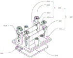
Fig. 1 is a schematic structural view of a rotary retractable take-up mechanism according to an exemplary embodiment.
Fig. 2 is a schematic structural view of a rotary retractable take-up mechanism according to an exemplary embodiment.
FIG. 3 is a schematic diagram illustrating a telescoping mechanism according to an exemplary embodiment.
Fig. 4 is a schematic structural view of an unloading section shown according to an exemplary embodiment.
FIG. 5 is a schematic diagram of a feed device according to an exemplary embodiment.
Fig. 6 is a schematic structural view of a compression device according to an exemplary embodiment.
Fig. 7 is a schematic structural view of a start cartridge device according to an exemplary embodiment.
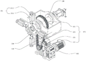
FIG. 8 is a schematic diagram of a drive assembly shown in accordance with an exemplary embodiment.
Detailed Description
In order to make the objects, technical solutions and advantages of the embodiments of the present application clearer, the technical solutions in the embodiments of the present application will be clearly and completely described below with reference to the drawings in the embodiments of the present application, and it is obvious that the described embodiments are some embodiments of the present application, but not all embodiments. All other embodiments, which can be derived by a person skilled in the art from the embodiments given herein without making any creative effort, shall fall within the protection scope of the present application. It should be noted that the embodiments and features of the embodiments in the present application may be arbitrarily combined with each other without conflict.
In the description of the present application, it is further noted that, unless expressly stated or limited otherwise, the terms "disposed," "mounted," and "connected" are to be construed broadly, e.g., as meaning fixedly connected, detachably connected, or integrally connected; may be directly connected or indirectly connected through an intermediate. The specific meaning of the above terms in the present application can be understood in a specific case by those of ordinary skill in the art.
In the related technology, the discharging turnover plate in the winding machine is of a connecting rod structure and is controlled by a cylinder. In the implementation process, ventilation pipelines need to be arranged at the centers of the main shaft and the telescopic mechanism, the structure is complex, and the phenomenon of blocking is easy to occur. During the winding operation, the material plates are easy to scratch, and the quality of the material plates is influenced. And the swing arm extending structure of the winder has unreasonable structure, is inconvenient to operate during coil unloading, and is not beneficial to coil unloading.
In one example, the swing arm telescopic structure of the winding machine adopts a worm gear structure, and the glass fiber product is wound by utilizing a worm gear and a worm to transfer torque. However, the worm and gear structure has high requirements on the machining and installation accuracy of parts, the structure is easy to generate heat, and the worm and gear are used as main torque power parts, so that the material requirement is high, the equipment cost is improved, and the popularization and the use of industrial production are not facilitated.
In another example, the swing arm extending structure of rolling machine still for example adopts the cylinder structure, and the output power of cylinder is not enough among the cylinder structure, leads to its rolling action unstable, and the atress is uneven, makes its flitch appear easily that to retract the difficult circumstances of rolling down.
In another example, the swing arm telescopic structure of the winding machine further adopts a hinge structure, the hinge structure controls the swing arm to stretch and retract through the guide pillar, the guide pillar structure is stressed unevenly, and the telescopic mechanism is extremely easy to be blocked.
In order to solve the above problem, the present application provides a rotary telescopic winding mechanism, including: a main shaft; the main shaft is sleeved on the telescopic mechanism, and the telescopic mechanism is arranged in the main shaft and can move along the axial direction of the main shaft; the winding mechanism is sleeved on the main shaft, and the main shaft is arranged to drive the winding mechanism to rotate; the winding mechanism comprises an unloading part and a connecting rod assembly, the unloading part is arranged at one end part of the connecting rod assembly, and the other end part of the connecting rod assembly is connected with the telescopic mechanism; the unloading part comprises a baffle and at least one turning plate, and the telescopic mechanism drives the turning plate to rotate relative to the baffle through the connecting rod assembly. The telescopic machanism of this application rotatory telescopic winding mechanism is integrated in the main shaft, and simple structure easily operates, and processing installation accuracy requires lowly, has effectually solved among the prior art the easy dead problem of card of telescopic machanism. Simultaneously, winding mechanism and telescopic machanism cooperation utilize telescopic machanism to drive winding mechanism's the relative baffle motion of turning over the board to accomplish the uninstallation action, conveniently unload the book, save the labour, avoid the rolling in-process to turn over the board and scrape the flitch, improve the rolling quality.
In an exemplary embodiment, as shown in fig. 1-2, a rotary retractable take-up mechanism includes a spindle 100, a retractable mechanism 200, and a take-up mechanism 300.
The main shaft 100 is sleeved on the telescopic mechanism 200, so that the telescopic mechanism 200 is integrated in the main shaft 100, wiring is less, the structure is simple, and the realization is easy. The telescopic mechanism 200 is provided so as to be movable in the axial direction thereof (refer to the X-axis direction shown in fig. 1) within the main shaft 100; on the premise of ensuring that the telescopic mechanism 200 can move, the main shaft 100 protects the telescopic mechanism 200, and the exposed area of the telescopic mechanism 200 is reduced.
In order to further protect the spindle 100, a housing 110 may be provided, and the spindle 100 may rotatably pass through the housing 110. For example, a first bearing portion 223 and a second bearing portion 224 may be disposed on a circumferential outer side wall of the spindle 100, the first bearing portion 223 and the second bearing portion 224 are respectively embedded in two opposite side walls of the box body 110, and the spindle 100 sequentially passes through the first bearing portion 223 and the second bearing portion 224, so that the spindle 100 is rotatably connected with the box body 110.
The first bearing portion 223 may be, for example, a deep groove ball bearing, an outer ring of the first bearing portion 223 is fixedly connected to the box 110, an inner ring of the first bearing portion 223 is fixedly connected to a circumferential outer sidewall of the main shaft 100, and a ball is disposed between the outer ring and the inner ring, so that the main shaft 100 drives the inner ring to rotate relative to the outer ring.
The second bearing portion 224 may be, for example, a double-row tapered roller bearing, an outer ring of the second bearing portion 224 is fixedly connected to the box 110, an inner ring of the second bearing portion 224 is fixedly connected to a circumferential outer sidewall of the main shaft 100, and double-row tapered rollers are disposed between the outer ring and the inner ring, so that the main shaft 100 drives the inner ring to rotate relative to the outer ring.
Of course, it is understood that the connection between the main shaft 100 and the casing 110 is not limited to the first bearing portion 223 and the second bearing portion 224, and two first bearing portions 223 or two second bearing portions 224 may be provided. Under the action of the bearing portion, it is sufficient that the bearing portion can support the main shaft 100, and reduce the friction coefficient between the housing 110 and the main shaft 100 during the rotation process, so as to ensure the rotation precision.
The winding mechanism 300 is sleeved on the main shaft 100, and the main shaft 100 is set to drive the winding mechanism 300 to rotate to execute winding action, so that the winding requirement is met.
The winding mechanism 300 includes an unloading portion 310 and a connecting rod assembly 320, the unloading portion 310 is disposed at one end of the connecting rod assembly 320, and the other end of the connecting rod assembly 320 is connected to the telescoping mechanism 200. When the telescopic mechanism 200 moves in the axial direction of the main shaft 100, the telescopic mechanism 200 can pull the unloading part 310 to move through the connecting rod assembly 320, so as to realize unloading.
The unloading part 310 comprises a baffle 311 and at least one turning plate 312, and the telescopic mechanism 200 drives the turning plate 312 to rotate relative to the baffle 311 through a connecting rod assembly 320. The turning plate 312 limits the material plate, so that the material plate can be stably arranged on the winding mechanism 300. The flap 312 and the flap 311 have a predetermined angle therebetween, and the predetermined angle may be, for example, 0 ° to 150 °. When the turning plate 312 moves relative to the baffle 311, the opening angle between the turning plate 312 and the baffle 311 is adjustable, so that scraping of the material plate during winding is avoided, and the winding quality is improved. The turning plate 312 can be, for example, an umbrella-shaped mechanical movable structure, so that the material can be unloaded conveniently when the rolling is completed, and time and labor are saved.
In an exemplary embodiment, as shown in fig. 1-2, the telescoping mechanism 200 may include a first driving portion 210 and a moving portion 220, the first driving portion 210 being connected to a link assembly 320 through the moving portion 220. In the driving state, the first driving unit 210 drives the telescopic mechanism 200 to move in the axial direction of the main shaft (refer to the X-axis direction shown in fig. 1).
As shown in fig. 3, the first driving part 210 may be, for example, a driving cylinder. The piston part of the driving cylinder extends into the main shaft 100 and is fixedly connected with the telescopic mechanism 200, and the cylinder body of the driving cylinder is fixedly connected with the axial outer side wall of the main shaft 100. The end of the first driving part 210 far from the main shaft 100 is provided with an air-electric slip ring 211, which ensures the normal operation of an air circuit and an electric circuit during the driving process. The gas-electric slip ring 211 is used for communication transmission between the first driving part 210 and a control part (not shown in the figure), the gas-electric slip ring 211 is used for simultaneously carrying current and fluid, and the current-carrying part is an electric slip ring which can be used for transmitting power, weak signals and the like; the fluid-carrying portion may be used to transfer fluid such as compressed air, hydraulic oil, and steam to form a complete vacuum channel, so as to achieve the telescopic effect of the first driving portion 210.
In the present embodiment, as shown in fig. 3, the moving part 220 includes a moving telescopic shaft 221 and a moving ring 222, one end of the moving telescopic shaft 221 is fixedly connected to the first driving part 210, and the other end thereof penetrates through the main shaft 100 and is fixedly connected to the moving ring 222. The movable ring 222 is fitted around the movable telescopic shaft 221 and is fixedly connected to the circumferential outer wall of the movable telescopic shaft 221. The moving ring 222 is hinged to the connecting rod assembly 320, the first driving portion 210 drives the moving ring 222 to move by moving the telescopic shaft 221, and the moving ring 222 provides a pulling force to drive the connecting rod assembly 320 to move.
In order to ensure the sliding effect of the movable telescopic shaft 221 in the main shaft 100, a sleeve portion 230 may be provided on an axially outer side wall of the movable telescopic shaft 221. The sleeve portion 230 can support the movable telescopic shaft 221, so as to prevent the movable telescopic shaft 221 from deviating from the axis and affecting the movement precision, and when the movable telescopic shaft 221 makes a linear movement, the friction coefficient between the movable telescopic shaft 221 and the main shaft 100 can be reduced, so as to ensure the movement precision.
In an exemplary embodiment, as shown in fig. 1-2, the winding mechanism 300 further includes a turntable 330 and a swing arm assembly 340, and the turntable 330 is sleeved on the main shaft 100, so that the main shaft 100 can drive the turntable 330 to rotate synchronously.
The swing arm assembly 340 is installed on the turntable part 330, the unloading part 310 is installed on the swing arm assembly 340, and the turntable part 330 drives the swing arm assembly 340 and the unloading part 310 to rotate together in a rolling state. The connecting rod assembly 320 is connected with the unloading part 310 through the swing arm assembly 340, and in the unloading state, the connecting rod assembly 320 drives the unloading part 310 to move so as to complete unloading.
In the present embodiment, the swing arm assembly 340 includes a plurality of swing arm heads 341, the swing arm heads 341 being disposed in a radial direction of the main shaft 100, each of the swing arm heads 341 being provided with the unloading section 310. Wherein, swing arm subassembly 340 for example can set up four swing arm heads 341, four swing arm heads 341 along main shaft 100's circumference equipartitions for swing arm head 341 can provide the holding power of four directions for the flitch, makes the rolling in-process, and the flitch atress is even, has promoted stability.
Of course, it should be understood that the above illustration of the number of the swing arm heads 341 is only for illustrative purposes of the present embodiment and not for limiting the present application. The specific number of the swing arm heads 341 is determined according to actual needs. Wherein, each swing arm head 341 is provided with an unloading part 310 so as to stably unload materials.
In this embodiment, one of the swing arm heads 341 is further provided with a start chuck device 3411, and the start chuck device 3411 is fixedly connected to the swing arm head 341. The start chuck device 3411 is disposed at a position capable of clamping the start of the material plate, so as to prevent the start of the material plate from scattering due to non-fixity and affecting the winding.
As shown in fig. 7, the head-start chuck device 3411 includes a connecting plate 3411-1, a clamping portion 3411-2 and a wrench 3411-3, wherein the clamping portion 3411-2 is fixedly connected to one of the swing arm heads 341 through the connecting plate 3411-1.
The connecting plate 3411-1 includes a first connecting body 3411-11 and a second connecting body 3411-12, the first connecting body 3411-11 is fixedly connected to one of the swing arm heads 341, the first connecting body 3411-11 and the second connecting body 3411-12 are a unitary structure, and the second connecting body 3411-12 is bent with respect to the first connecting body 3411-11 such that the first connecting body 3411-11 and the second connecting body 3411-12 form a predetermined angle therebetween, which may be, for example, 120 ° to 150 °.
Clamping portion 3411-2 includes clamping plates 3411-21 and supporting plates 3411-22, clamping plates 3411-21 are in interference contact with second connecting bodies 3411-12, and supporting plates 3411-22 are disposed parallel to clamping plates 3411-21 and are movably connected to second connecting bodies 3411-12, so that the distance between clamping plates 3411-21 and second connecting bodies 3411-12 can be adjusted.
Impact wrench 3411-3 is passed through support plates 3411-22 and into abutting engagement with clamping plates 3411-21. Wherein, locking screws are arranged at both sides of the supporting plates 3411-22, and the locking screws pass through the supporting plates 3411-22 and the clamping plates 3411-21 and are rotatably connected with the supporting plates 3411-22. When the spanner 3411-3 is rotated, the clamping plates 3411-21 may be moved in the axial direction of the spanner 3411-3 to adjust the distance between the clamping plates 3411-21 and the second connecting bodies 3411-12 so as to clamp the start position of the flitch. The holding plates 3411-21 and the supporting plates 3411-22 may be unloaded by rotating locking screws provided on both sides of the supporting plates 3411-22. The locking screw is preferably a fisheye screw, which is flexible and smart in design, and can stably fix the support plates 3411-22 and the clamping plates 3411-21 on the second connecting body 3411-12, and when the support plates 3411-22 and the clamping plates 3411-21 need to be disassembled, the assembly is convenient and labor-saving.
In the present embodiment, as shown in fig. 4, the unloading section 310 includes a flap 311, a flap 312, and a flap telescopic lever 313 and a flap support 314. The flap 312 is respectively connected with the swing arm head 341 and the flap support 314 through a flap telescopic rod 313, and the flap support 314 is arranged on the connecting rod assembly 320. Under the action of external force, the link assembly 320 drives the flap telescopic rod 313 to move, so that the flap 312 rotates relative to the baffle 311.
Wherein, the turning plate telescopic rod 313 is provided with an anchor ear 3131, the turning plate 312 is provided with a connecting ear 3121, the first end of the turning plate telescopic rod 313 is rotatably connected with the connecting ear 3121, the second end of the turning plate telescopic rod 313 passes through the anchor ear 3131 and is fixedly connected with the anchor ear 3131, and the anchor ear 3131 is fixedly connected with the lower end face of the swing arm head 341. The flap support 314 is fixedly mounted to the turntable portion 330. Wherein the flap 312 is rotatably connected to the flap support 314 by means of the connecting ears 3121.
Under the action of external force, the link assembly 320 drives the swing arm head 341 to move, the anchor ear 3131 on the swing arm head 341 drives the turning plate telescopic rod 313 to move, and the turning plate telescopic rod 313 drives the turning plate 312 to move. Because the turning plate 312 is rotatably connected with the turning plate support 314, the turning plate support 314 is fixedly connected with the turntable part 330, the turning plate 312 is controlled by the turning plate support 314, the free end part of the turning plate 312 moves towards the direction far away from the baffle 311 so as to adjust the preset included angle between the turning plate 312 and the baffle 311, the turning plate 312 has an umbrella-shaped opening and closing mechanical structure, the flitch loses the support of the turning plate 312 and is separated from the swing arm head 341, and the unloading is completed.
In the present embodiment, as shown in fig. 2, the link assembly 320 includes a plurality of guide portions 321 and a plurality of link portions 322, the guide portions 321 correspond to the link portions 322 one by one, and one guide portion 321 and one link portion 322 are disposed between each unloading portion 310 and the telescoping mechanism 200 to realize the linkage between the unloading portion 310 and the telescoping mechanism 200.
One end of the link 322 is connected to the swing arm head 341 through the guide 321, and the other end of the link 322 is hinged to the moving ring 222 of the telescopic mechanism 200. The connecting rod 322 has high structural strength and is flexible to use.
As shown in fig. 8, the guide portion 321 includes a guide block 3211 and a swing arm head guide rod 3212, the guide block 3211 is fixedly connected to the turntable portion 330, one end of the swing arm head guide rod 3212 passes through the guide block 3211 and is fixedly connected to the swing arm head 341, the swing arm head guide rod 3212 is slidably connected to the guide block 3211, the other end of the swing arm head guide rod 3212 is hinged to one end of the link portion 322, and the other end of the link portion 322 is hinged to the moving ring 222. The first driving portion 210 is in a driving state, and drives the movable telescopic shaft 221 to move along the main shaft 100, the movable telescopic shaft 221 drives the movable ring 222 to move, the movable ring 222 provides a pulling force to the connecting rod portion 322, and the connecting rod portion 322 drives the swing arm head guide rod 3212 to slide along the guide block 3211, so as to drive the unloading portion 310 to move. The guide block 3211 may be a linear copper bush slider, so as to ensure that the swing arm head guide rod 3212 can slide on the guide block 3211, and is stable in operation and low in noise.
In an exemplary embodiment, as shown in fig. 1-2, the rotary retractable winding mechanism further includes a driving assembly 400, and the driving assembly 400 can drive the spindle 100 to rotate around its axis direction, so as to drive the winding mechanism 300 to rotate, thereby completing the winding action of the flitch.
The driving assembly 400 includes a second driving part 410 and a transmission part 420, and the second driving part 410 is in transmission connection with the main shaft 100 through the transmission part 420. The second driving part 410 may be, for example, a reduction motor, and provides torque force to the spindle 100 and the winding mechanism 300.
As shown in fig. 8, the transmission part 420 includes a first sprocket 421, a second sprocket 422, and a transmission chain 423. The first chain wheel 421 can be a driven chain wheel, and is fixedly connected with the main shaft 100. The second sprocket 422 may be a driving sprocket, and is fixedly connected to the second driving portion 410, and the first sprocket 421 is drivingly connected to the second sprocket 422 through a driving chain 423. Wherein, the lower terminal surface of box 110 is provided with the opening, and drive chain 423 can stretch out to the outside from the box, guarantees the normal operating of transmission portion 420.
In this embodiment, the transmission part 420 further includes an auxiliary sprocket 424, the auxiliary sprocket 424 is rotatably connected to the turntable part 330, the auxiliary sprocket 424 is disposed outside the transmission chain 423 and is engaged with the transmission chain 423, so as to further improve the stability of the transmission chain 423 during transmission.
In an exemplary embodiment, as shown in fig. 1-2, the rotating telescoping take-up mechanism further includes a frame structure 500, with the take-up mechanism 300 mounted to the frame structure 500. The frame structure 500 comprises a feed opening 510, through which feed opening 510 the flitch is fed into the winding mechanism 300.
In this embodiment, as shown in fig. 1-2, the rotary retractable winding mechanism includes a feeding device 600 connected to the frame structure 500 and located at the feeding hole 510. The feeding device 600 feeds the material plate into the start chuck device 3411 of the winding mechanism 300 through the feeding hole 510, so as to realize automatic winding.
As shown in fig. 5, the feeding device 600 includes a pressure detecting part 610, an adjusting part 620, and a stand hinge 630, and the pressure detecting part 610 and the adjusting part 620 are electrically connected. The pressure detecting portion 610 may detect a pressure applied to the flitch to determine whether a current tension value of the flitch is within a preset range. The pressure detection unit 610 is hinged to the bracket 623 by a bracket hinge 630.
The adjusting part 620 includes at least one slack adjuster 621, a bracket 623, and a plurality of guide bars 622, and the slack adjuster 621 and the plurality of guide bars 622 are mounted on the bracket 623. The tightness adjusting part 621 can adjust the pressure applied to the material plate, so that the tension value applied to the material plate is within a preset range, and smooth proceeding of the detection process and the control process is ensured. The number of the guide rods 622 may be four, two guide rods are disposed on each of both sides of the slack adjuster 621, and the four guide rods 622 prevent the deviation from occurring in the left and right directions when the material plate moves.
The slack adjuster 621 may include, for example, a first one-way roller 6211, a second one-way roller 6212, two slack adjusting wheels 6213, and two adjusting stoppers 6214, where the two adjusting stoppers 6214 are perpendicular to the bracket 623, and the lower end of the adjusting stopper 6214 is fixedly connected to the bracket 623. Two end parts of the first one-way roller 6211 are respectively connected with the corresponding adjusting baffle 6214 in a rotating way through one-way bearings, the adjusting baffle 6214 is provided with a slot, an adjusting block 6214-1 is arranged in the slot, the lower end part of the elastic adjusting wheel 6213 penetrates through the adjusting block 6214-1 and is connected with the adjusting baffle 6214 in a rotating way, the elastic adjusting wheel 6213 is connected with the adjusting block 6214-1 in a rotating way, and two end parts of the second one-way roller 6212 are respectively connected with the corresponding adjusting block 6214-1 in a rotating way through one-way bearings. Under the action of external force, the tightness adjusting wheel 6213 rotates, so that the adjusting block 6214-1 drives the second one-way roller 6212 to move along the tightness adjusting wheel 6213, and the distance between the first one-way roller 6211 and the second one-way roller 6212 is adjusted. The material plate is arranged between the first unidirectional roller 6211 and the second unidirectional roller 6212, and the clamping force between the first unidirectional roller 6211 and the second unidirectional roller 6212 is adjusted by adjusting the distance between the first unidirectional roller 6211 and the second unidirectional roller 6212. The feed is prevented from backing up under the nip force between the first one-way roller 6211 and the second one-way roller 6212.
In an exemplary embodiment, as shown in fig. 1-2, the rotary retractable take-up mechanism further includes a hold-down device 700 coupled to the frame structure 500, the hold-down device 700 configured to hold down the flitch to provide tension to the flitch to prevent the flitch from backing up.
In the present embodiment, as shown in fig. 6, the pressing device 700 includes a third driving part 710 and a pressing part 720, the third driving part 710 is connected to the frame structure 500, and the third driving part 710 drives the pressing part 720 to move toward the flitch to press the flitch. The third driving portion 710 is, for example, an air cylinder, a cylinder body of the air cylinder is fixedly connected to the frame structure 500, a piston rod of the air cylinder is fixedly connected to the pressing portion 720, and the third driving portion 710 drives the pressing portion 720 to perform a linear motion.
In this embodiment, the pressing portion 720 includes a pressing guide rod 721, a pressing guide block 722 and a pressing wheel 723, the pressing guide block 722 is sleeved on the pressing guide rod 721 and is slidably connected with the pressing guide rod 721, the pressing wheel 723 is rotatably connected with the pressing guide rod 721, and the pressing guide rod 721 provides motion guide for the pressing wheel 723. In the driven state, the pressing wheel 723 moves relative to the material plate, presses the material plate, provides tension thereto by pressing the material plate, and prevents backward movement.
In this embodiment, the rotating and retractable winding mechanism further includes a display portion (not shown) and a control portion (not shown), the display portion is disposed on the frame structure 500, and the display portion is electrically connected to the control portion. The control part is electrically connected with the winding mechanism 300 and the telescoping mechanism 200 respectively.
The display unit and the control unit may be integrated into a PLC (Programmable Logic Controller, PLC for short) touch panel having a control program, and the PLC touch panel may display an operation state of the winding machine, and the control program may set a winding speed frequency and perform a winding-down operation. Through the PLC touch-sensitive screen that has control program, show and control the rolling machine, can avoid in the current equipment button for independent control, can't look over operating condition's problem at any time with the main part equipment linkage.
The display unit may be a liquid crystal display on the frame structure 500, and the control unit may be an industrial computer with a control program.
Here, it should be noted that, in the present application, the type of the display unit and the type of the control unit are not specifically set, and the display unit may display the winding parameter and the winding state, and the control unit may control the winding speed frequency and the winding-down.
In the implementation process, the following steps can be executed:
and S1, before the winding is prepared, presetting the working initial speed of the winding machine and the preset length to be wound through a PLC touch screen control program. The angle between the turning plate 312 and the baffle 311 is preset to prevent the material plate from being scratched in the winding process.
S2, loosening the two tension adjusting wheels 6213 on the tension adjusting portion 621, disposing the material plate to be wound between the first one-way roller 6211 and the second one-way roller 6212, and adjusting the clamping force between the first one-way roller 6211 and the second one-way roller 6212 by adjusting the distance between the first one-way roller 6211 and the second one-way roller 6212. When the flitch passes through the start-up chuck device 3411, the tightening wrench 3411-3 is rotated to move the clamping plates 3411-21 in the axial direction of the tightening wrench 3411-3, so as to adjust the distance between the clamping plates 3411-21 and the second connecting bodies 3411-12, thereby clamping the start-up position of the flitch. The feeding device 600 and the start chuck device 3411 ensure that the flitch is easy to fix and not easy to back up in the feeding process.
S3, starting the second driving part 410, and the spindle 100 drives the telescoping mechanism 200 and the winding mechanism 300 to rotate together to perform a winding operation under the driving of the transmission part 420. In the winding process, the pressure detection part 610 can detect the tension of the material plate, and the PLC touch screen control program can adjust the winding speed according to the detected tension and is matched with the driving speed of the second driving part 410. When the flitch touches the pressing wheel 723 in the pressing device 700 and enters the pressing range of the pressing wheel 723 in the flitch winding process, the third driving part 710 pushes the pressing guide rod 721 to eject out to press the flitch; the pressing device 700 ensures that the material plate is stably rolled in the rolling engineering and is not easy to reverse and deviate.
The working state of the whole winding working process can be checked at any time through the PLC touch screen.
And S4, when the winding length of the material plate reaches the preset length, the second driving part 410 decelerates to stop working, the main shaft 100 of the winding machine stops rotating, and the winding mechanism 300 stops winding.
S5, loosening the spanner 3411-3 in the collet 3411 to loosen the flitch from the front of the clamping plates 3411-21 and the second connecting bodies 3411-12; through the control of the control program of the PLC touch screen, the first driving part 210 enables the movable telescopic shaft 221 to be ejected along the axial direction of the main shaft, meanwhile, the movable ring 222 is ejected along the axial direction of the main shaft along with the movable telescopic shaft 221, the swing arm head 341 is driven to be tightened towards the central direction of the turntable part, meanwhile, the plurality of turning plates 312 are driven to be turned downwards, the plurality of turning plates 312 which are closed like an umbrella are of a turning structure, the rolled material can be easily rolled downwards, the whole rolling work is completed, and time and labor are saved.
The winding mechanism integrates the telescopic mechanism into the spindle, drives the winding mechanism to wind, and solves the problem that the spindle of the existing equipment is blocked easily. The angle of predetermineeing between board and the baffle is turned over in the regulation, avoids forming the scraping to the flitch. And the turning plate is driven to be closed like an umbrella by the telescopic mechanism, so that the coil can be conveniently unloaded. The winding machine is combined with the display part and the control part, the telescopic mechanism and the winding mechanism of the winding machine can be linked with the driving assembly, the winding working state can be observed at any time, and the full-automatic mode of the winding machine is realized.
Finally, it should be noted that: the above embodiments are only used for illustrating the technical solutions of the present application, and not for limiting the same. Although the present application has been described in detail with reference to the foregoing embodiments, it should be understood by those of ordinary skill in the art that: the technical solutions described in the foregoing embodiments may still be modified, or some technical features may be equivalently replaced; and such modifications or substitutions do not depart from the spirit and scope of the corresponding technical solutions in the embodiments of the present application.
Claims (20)
1. The utility model provides a rotatory telescopic winding mechanism which characterized in that includes:
a main shaft;
the main shaft is sleeved on the telescopic mechanism, and the telescopic mechanism is arranged in the main shaft and can move along the axial direction of the main shaft;
the winding mechanism is sleeved on the main shaft, and the main shaft is arranged to drive the winding mechanism to rotate;
the winding mechanism comprises an unloading part and a connecting rod assembly, the unloading part is arranged at one end part of the connecting rod assembly, and the other end part of the connecting rod assembly is connected with the telescopic mechanism; the unloading part comprises a baffle and at least one turning plate, and the telescopic mechanism drives the turning plate to rotate relative to the baffle through the connecting rod assembly.
2. The rotating telescopic winding mechanism according to claim 1, wherein the baffle and the flap have a predetermined angle.
3. The rotating telescopic winding mechanism according to claim 1, characterized in that the winding mechanism comprises a first drive part and a moving part, the first drive part being connected to the linkage assembly via the moving part.
4. The rotating-telescoping take-up mechanism of claim 3, wherein the moving portion comprises a moving telescoping shaft and a moving ring; one end part of the movable telescopic shaft is fixedly connected with the first driving part, and the other end part of the movable telescopic shaft penetrates through the main shaft and is fixedly connected with the movable ring;
wherein the moving ring is hinged to the connecting rod assembly.
5. The rotary telescopic winding mechanism according to claim 1, wherein the winding mechanism comprises a turntable part and a swing arm assembly, the turntable part is sleeved on the main shaft, the swing arm assembly is mounted on the turntable part, and the unloading part is mounted on the swing arm assembly;
wherein the link assembly is connected to the unloading section through the swing arm assembly.
6. The rotary retractable take-up mechanism of claim 5, wherein the swing arm assembly comprises a plurality of swing arm heads, the plurality of swing arm heads being arranged in a radial direction of the spindle;
wherein, every swing arm head all is provided with uninstallation portion.
7. The rotary telescoping take-up mechanism of claim 6, wherein the linkage assembly includes a plurality of guide portions and a plurality of linkage portions;
one end of the connecting rod part is connected with the swing arm head through the guide part, and the other end of the connecting rod part is hinged with the telescopic mechanism.
8. The rotary telescopic winding mechanism according to claim 7, wherein the guide part comprises a guide block and a swing arm head guide rod, the swing arm head guide rod penetrates through the guide block to be connected with the swing arm head, and the swing arm head guide rod is connected with the guide block in a sliding manner.
9. The rotary telescopic winding mechanism according to claim 6, wherein one of the swing arm heads is further provided with a starting chuck device, and the starting chuck device is fixedly connected with the swing arm head.
10. The rotary telescopic winding mechanism according to claim 6, wherein the unloading section further comprises a flap telescopic lever and a flap support;
the turning plate is connected with the swing arm head and the turning plate support through the turning plate telescopic rod piece respectively, and the turning plate support is installed on the connecting rod assembly;
under the action of external force, the connecting rod assembly drives the turning plate telescopic rod piece to move, so that the turning plate rotates relative to the baffle.
11. The rotating telescopic winding mechanism of claim 1, further comprising a driving assembly, wherein the driving assembly drives the spindle to rotate, and further drives the winding mechanism to rotate.
12. The rotating-telescoping take-up mechanism of claim 11, wherein the drive assembly includes a second drive portion and a transmission portion; the second driving part is in transmission connection with the main shaft through the transmission part.
13. The rotary retractable take-up mechanism of claim 12, wherein the transmission portion comprises a first sprocket, a second sprocket and a transmission chain, the first sprocket is fixedly connected with the main shaft, the second sprocket is fixedly connected with the second driving portion, and the first sprocket is in transmission connection with the second sprocket through the transmission chain.
14. The rotating-telescoping windup mechanism of claim 1 further comprising a frame structure to which the windup mechanism is mounted;
the frame structure comprises a feed inlet, and the material plate passes through the feed inlet to the winding mechanism.
15. A rotary telescopic winding mechanism according to claim 14, characterized in that it comprises a feeding device connected to the frame structure and located at the feeding opening.
16. The rotating telescopic winding mechanism according to claim 15, wherein the feeding device comprises a pressure detection part and an adjustment part, and the pressure detection part and the adjustment part are electrically connected.
17. The rotating-telescopic winding mechanism according to claim 16, wherein the adjustment part comprises at least one slack adjustment part, a plurality of guide rods and a bracket, the slack adjustment part and the plurality of guide rods being mounted to the bracket.
18. The rotating-telescoping take-up mechanism of claim 14, further comprising a hold-down device coupled to the frame structure;
the pressing device is configured to press the flitch.
19. The rotating telescopic winding mechanism according to claim 18, wherein the pressing device comprises a third driving portion and a pressing portion, the third driving portion is connected with the frame structure, and the third driving portion drives the pressing portion to move towards the material plate to press the material plate.
20. The rotating telescopic winding mechanism according to claim 14, further comprising a display part and a control part, wherein the display part is disposed on the frame structure, and the display part is electrically connected to the control part;
the control part is respectively electrically connected with the winding mechanism and the telescopic mechanism.
Priority Applications (1)
| Application Number | Priority Date | Filing Date | Title |
|---|---|---|---|
| CN202111026018.5A CN113682859B (en) | 2021-09-02 | 2021-09-02 | Rotary telescopic winding mechanism |
Applications Claiming Priority (1)
| Application Number | Priority Date | Filing Date | Title |
|---|---|---|---|
| CN202111026018.5A CN113682859B (en) | 2021-09-02 | 2021-09-02 | Rotary telescopic winding mechanism |
Publications (2)
| Publication Number | Publication Date |
|---|---|
| CN113682859A true CN113682859A (en) | 2021-11-23 |
| CN113682859B CN113682859B (en) | 2023-06-02 |
Family
ID=78585016
Family Applications (1)
| Application Number | Title | Priority Date | Filing Date |
|---|---|---|---|
| CN202111026018.5A Active CN113682859B (en) | 2021-09-02 | 2021-09-02 | Rotary telescopic winding mechanism |
Country Status (1)
| Country | Link |
|---|---|
| CN (1) | CN113682859B (en) |
Cited By (2)
| Publication number | Priority date | Publication date | Assignee | Title |
|---|---|---|---|---|
| CN115258753A (en) * | 2022-06-28 | 2022-11-01 | 江苏准信自动化科技股份有限公司 | Fine board rolling machine of glass |
| CN118270574A (en) * | 2024-06-04 | 2024-07-02 | 常州市新创智能科技有限公司 | Carbon plate winding device |
Citations (7)
| Publication number | Priority date | Publication date | Assignee | Title |
|---|---|---|---|---|
| CN203593439U (en) * | 2013-12-18 | 2014-05-14 | 宁波方力科技股份有限公司 | Recoiling machine with single air cylinder acting on coiling device |
| CN204384607U (en) * | 2015-01-08 | 2015-06-10 | 宁波方力科技股份有限公司 | A kind of plastic pipe double reeler |
| CN109051952A (en) * | 2018-10-19 | 2018-12-21 | 常州市新创智能科技有限公司 | A kind of pultrusion composite materials adjustable tension wrap-up and its application method |
| CN109279427A (en) * | 2018-10-19 | 2019-01-29 | 常州市新创智能科技有限公司 | A kind of pultrusion composite materials automatic winding technique |
| CN110980430A (en) * | 2019-12-06 | 2020-04-10 | 大连春禾智能科技有限公司 | Universal pipe coiling machine for PE and PERT pipes |
| CN111547567A (en) * | 2020-06-11 | 2020-08-18 | 杭州全茂科技有限公司 | Full-automatic pipe winder |
| CN212687180U (en) * | 2020-06-11 | 2021-03-12 | 杭州全茂科技有限公司 | Full-automatic pipe winder |
-
2021
- 2021-09-02 CN CN202111026018.5A patent/CN113682859B/en active Active
Patent Citations (7)
| Publication number | Priority date | Publication date | Assignee | Title |
|---|---|---|---|---|
| CN203593439U (en) * | 2013-12-18 | 2014-05-14 | 宁波方力科技股份有限公司 | Recoiling machine with single air cylinder acting on coiling device |
| CN204384607U (en) * | 2015-01-08 | 2015-06-10 | 宁波方力科技股份有限公司 | A kind of plastic pipe double reeler |
| CN109051952A (en) * | 2018-10-19 | 2018-12-21 | 常州市新创智能科技有限公司 | A kind of pultrusion composite materials adjustable tension wrap-up and its application method |
| CN109279427A (en) * | 2018-10-19 | 2019-01-29 | 常州市新创智能科技有限公司 | A kind of pultrusion composite materials automatic winding technique |
| CN110980430A (en) * | 2019-12-06 | 2020-04-10 | 大连春禾智能科技有限公司 | Universal pipe coiling machine for PE and PERT pipes |
| CN111547567A (en) * | 2020-06-11 | 2020-08-18 | 杭州全茂科技有限公司 | Full-automatic pipe winder |
| CN212687180U (en) * | 2020-06-11 | 2021-03-12 | 杭州全茂科技有限公司 | Full-automatic pipe winder |
Cited By (2)
| Publication number | Priority date | Publication date | Assignee | Title |
|---|---|---|---|---|
| CN115258753A (en) * | 2022-06-28 | 2022-11-01 | 江苏准信自动化科技股份有限公司 | Fine board rolling machine of glass |
| CN118270574A (en) * | 2024-06-04 | 2024-07-02 | 常州市新创智能科技有限公司 | Carbon plate winding device |
Also Published As
| Publication number | Publication date |
|---|---|
| CN113682859B (en) | 2023-06-02 |
Similar Documents
| Publication | Publication Date | Title |
|---|---|---|
| CN113682859A (en) | Rotary telescopic winding mechanism | |
| CN215100906U (en) | A winding device for protective film production | |
| CN223046871U (en) | An automatic feeding device for galvanized sheet winding drum | |
| CN221739548U (en) | A winding device for copper wire rolling | |
| CN218088059U (en) | A cloth winding mechanism | |
| CN107913920A (en) | Major diameter wrapper | |
| CN207632182U (en) | Winding equipment | |
| CN216604188U (en) | Cloth collection components of filter press | |
| CN204714157U (en) | A kind of pressure type reel system | |
| CN221216511U (en) | Filter cotton printing winding equipment | |
| JP2606784B2 (en) | Press machine | |
| CN113770185A (en) | Ten-die wire drawing machine convenient to replace wire drawing structure | |
| CN206663943U (en) | Plastic film compounding machine | |
| CN223645994U (en) | Constant tension winding system of pre-shrinker | |
| CN215905588U (en) | PC rod iron wire rod take-up | |
| CN218642016U (en) | PE film wind-up roll | |
| CN215828067U (en) | Coiling mechanism is used in cotton yarn production | |
| CN221456116U (en) | Sealing rubber strip cutting equipment with adjustable | |
| CN217397993U (en) | Plastic film quick replacement device | |
| CN223162865U (en) | Winding drum movable winding device | |
| CN220148699U (en) | Coiled material coiling mechanism | |
| CN222273629U (en) | Automatic tipping machine for impregnated bond paper | |
| CN219384196U (en) | Guiding roller device for inner-layer cylindrical packaging material | |
| CN222590004U (en) | Automatic pinch roller device of paper cutter | |
| CN219990726U (en) | Adjusting device for dry film slitting machine |
Legal Events
| Date | Code | Title | Description |
|---|---|---|---|
| PB01 | Publication | ||
| PB01 | Publication | ||
| SE01 | Entry into force of request for substantive examination | ||
| SE01 | Entry into force of request for substantive examination | ||
| GR01 | Patent grant | ||
| GR01 | Patent grant |