Throwing hopper used in cooperation with automobile brake pad pressing equipment
Technical Field
The invention relates to a device matched with automobile brake pad pressing equipment, in particular to a throwing hopper matched with the automobile brake pad pressing equipment.
Background
The automobile brake pad is formed by pressing powder through a pressing machine, the powder is manually put in a traditional pressing device, and the problem of low efficiency, inconvenience, safety and easy human pollution exists in the traditional processing mode for many years, so that the powder putting for automobile brake pad pressing is always a problem which is difficult to solve in the production of the brake pad. To solve the above problems, the present company has developed patent numbers: the powder feeding device for the automobile brake pad of ZL 201821464387.6 can be matched with pressing equipment to accurately and timely feed powder, but the situation that a large amount of dust overflows from a feed inlet of the feeding device when feeding occurs in the using process, so that the production environment is seriously polluted, and the invention is developed.
Disclosure of Invention
The technical purpose of the invention is to solve the existing problems, provide a throwing hopper used with the automobile brake pad pressing equipment, solve the problem of preventing throwing materials from flying while uniformly throwing materials, avoid the phenomenon of flying ash overflow when mixed powder is thrown, facilitate safer operation and avoid flying ash to pollute the environment.
The invention comprises a cylinder fixed at the outer side of a feeding hopper and a driving rod connected with the cylinder, an opening fork below the driving rod is sleeved on a driving shaft in the middle of the driving rod, and the adopted technical scheme is as follows: two ends of the transmission rod are movably fixed on two crank rods below the feeding hopper through fixing pins, the crank rods are fixed on the ends of the turnover shafts, the turnover shafts are movably connected through fixing rings fixed on two sides of the feeding hopper, the upper turnover shaft is fixedly provided with a dust sealing switch door, and the lower turnover shaft is fixedly provided with a feeding switch door; four linkage rods are divided into two groups and connected through a crank rod string, and a connecting plate is arranged in the middle of the feeding hopper and is fixedly connected with the cylinder.
In the above technical scheme: the four linkage rods are movably fixed in two groups through fixing pins by crank rods.
The invention has the following advantages: through the technical scheme, when the device is used after installation, powder can be fed from the opening of the ash sealing door at the upper part, the crank rod can be driven by the air cylinder under the integrally set accurate condition, the feeding switch door at the lower part is opened for feeding, and the ash sealing switch door at the upper part is automatically closed immediately, so that the problem of feeding flying can be solved, the flying ash overflow phenomenon during feeding of mixed powder is avoided, the device is beneficial to safer operation and prevents flying ash from splashing to pollute the environment.
Drawings
The invention is further described in detail below with reference to the figures and examples.
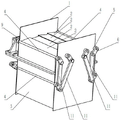
FIG. 1 is a schematic view of the present invention.
Fig. 2 is a schematic view of the internal structure of the invention with one side of the hopper hidden.
Fig. 3 is a schematic structural view of the invention with one side of the feeding hopper hidden, two lower switch doors opened and four upper switch doors closed.
In the figure: 1. the device comprises a feeding hopper, 2, a dust sealing switch door, 3, a feeding switch door, 4, a turnover shaft, 5, a fixing ring, 6, a crank rod, 7, a transmission rod, 8, a driving rod, 9, a cylinder, 10, a connecting plate, 11 and a linkage rod.
Detailed Description
Fig. 1, 2 and 3 show: the device comprises a cylinder 9 and a driving rod 8 which are fixed on the outer side of a feeding hopper 1, wherein an opening fork below the driving rod 8 is sleeved on a driving shaft in the middle of a driving rod 7, two ends of the driving rod 7 are movably fixed on two crank rods 6 below the feeding hopper 1 through fixing pins, the crank rods 6 are fixed on the ends of turning shafts 4, the turning shafts 4 are movably connected through fixing rings 5 fixed on two sides of the feeding hopper 1, an ash sealing switch door 2 is fixed on the turning shaft 4 above, and a feeding switch door 3 is fixed on the turning shaft 4 below; four linkage rods 11 are divided into two groups and connected in series through crank rods 6, and a connecting plate 10 is arranged in the middle of the feeding hopper 1 and is fixedly connected with a cylinder 9. The four linkage rods 11 are movably fixed in two groups through the crank rods 6 by fixing pins.
The working principle of the invention is as follows: the upper opening and the lower opening of a feeding hopper 1 used for feeding powder into an automobile brake pad pressing device, a square box body with four closed surfaces are arranged above the feeding hopper, four ash sealing switch doors 2 fixed on a turnover shaft 4 are arranged above the feeding hopper, the powder enters the feeding hopper 1 from the ash sealing switch doors 2, two feeding switch doors 3 fixed on the turnover shaft 4 are arranged below the feeding hopper, a transmission rod 7 is connected with two crank rods 6 below the transmission rod in a vertically staggered mode, the feeding switch doors 3 are opened in opposite directions when a cylinder 9 is pushed laterally, the powder is fed down rapidly, the ash sealing switch doors 2 above the feeding switch doors are divided into two groups and are closed simultaneously in opposite directions, dust overflow is prevented, the feeding switch doors 3 are closed in opposite directions when the cylinder 9 is pulled back, and the ash sealing switch doors 2 above the feeding switch doors are divided into two groups and are opened simultaneously in opposite directions to wait for material receiving.