CN113682402A - A vehicle axle installation equipment - Google Patents

A vehicle axle installation equipment Download PDF

Info

Publication number
CN113682402A
CN113682402A CN202110995624.1A CN202110995624A CN113682402A CN 113682402 A CN113682402 A CN 113682402A CN 202110995624 A CN202110995624 A CN 202110995624A CN 113682402 A CN113682402 A CN 113682402A
Authority
CN
China
Prior art keywords
axle
rod
block
sliding
sliding block
Prior art date
Legal status (The legal status is an assumption and is not a legal conclusion. Google has not performed a legal analysis and makes no representation as to the accuracy of the status listed.)
Granted
Application number
CN202110995624.1A
Other languages
Chinese (zh)
Other versions
CN113682402B (en
Inventor
王艳艳
崔晴晴
王灯强
Current Assignee (The listed assignees may be inaccurate. Google has not performed a legal analysis and makes no representation or warranty as to the accuracy of the list.)
Woyang Arcoso Machinery Co ltd
Original Assignee
Woyang Arcoso Machinery Co ltd
Priority date (The priority date is an assumption and is not a legal conclusion. Google has not performed a legal analysis and makes no representation as to the accuracy of the date listed.)
Filing date
Publication date
Application filed by Woyang Arcoso Machinery Co ltd filed Critical Woyang Arcoso Machinery Co ltd
Priority to CN202110995624.1A priority Critical patent/CN113682402B/en
Publication of CN113682402A publication Critical patent/CN113682402A/en
Application granted granted Critical
Publication of CN113682402B publication Critical patent/CN113682402B/en
Active legal-status Critical Current
Anticipated expiration legal-status Critical

Links

Images

Classifications

    • BPERFORMING OPERATIONS; TRANSPORTING
    • B62LAND VEHICLES FOR TRAVELLING OTHERWISE THAN ON RAILS
    • B62DMOTOR VEHICLES; TRAILERS
    • B62D65/00Designing, manufacturing, e.g. assembling, facilitating disassembly, or structurally modifying motor vehicles or trailers, not otherwise provided for
    • B62D65/02Joining sub-units or components to, or positioning sub-units or components with respect to, body shell or other sub-units or components
    • B62D65/12Joining sub-units or components to, or positioning sub-units or components with respect to, body shell or other sub-units or components the sub-units or components being suspensions, brakes or wheel units
    • BPERFORMING OPERATIONS; TRANSPORTING
    • B62LAND VEHICLES FOR TRAVELLING OTHERWISE THAN ON RAILS
    • B62DMOTOR VEHICLES; TRAILERS
    • B62D65/00Designing, manufacturing, e.g. assembling, facilitating disassembly, or structurally modifying motor vehicles or trailers, not otherwise provided for
    • B62D65/02Joining sub-units or components to, or positioning sub-units or components with respect to, body shell or other sub-units or components
    • B62D65/18Transportation, conveyor or haulage systems specially adapted for motor vehicle or trailer assembly lines

Landscapes

  • Engineering & Computer Science (AREA)
  • Manufacturing & Machinery (AREA)
  • Chemical & Material Sciences (AREA)
  • Combustion & Propulsion (AREA)
  • Transportation (AREA)
  • Mechanical Engineering (AREA)
  • Vehicle Body Suspensions (AREA)
  • Handcart (AREA)

Abstract

本发明公开了一种车桥安装设备,包括有承载板,所述承载板用于固定和托运车桥;螺纹杆,所述螺纹杆转动设置于所述承载板上部;滑动块,所述滑动块滑动设置于承载板上表面,所述滑动块下表面设置有限位块,所述螺纹杆与限位块螺纹连接;紧固件,所述紧固件设置于滑动块上表面,用于对车桥固定;运输板,所述运输板设置于承载板下方,且与承载板通过伸缩件连接;运输轮,所述运输轮设置于运输板下表面,用于对运输板移动。解决了常规的车桥在安装过程中,不能被固定,可能会出现晃动的问题。

Figure 202110995624

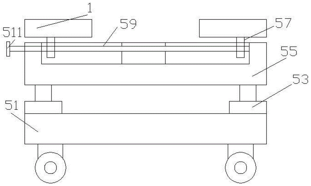
The invention discloses a vehicle axle installation device, which comprises a bearing plate, which is used for fixing and transporting a vehicle axle; a threaded rod, which is rotatably arranged on the upper part of the bearing plate; a sliding block, which is used for sliding the sliding The block is slidably arranged on the upper surface of the bearing plate, the lower surface of the sliding block is provided with a limit block, and the threaded rod is threadedly connected with the limit block; the fastener, which is arranged on the upper surface of the sliding block, is used for The axle is fixed; the transport plate is arranged under the carrier plate and is connected with the carrier plate through a telescopic piece; the transport wheel is arranged on the lower surface of the transport plate and is used to move the transport plate. It solves the problem that the conventional axle cannot be fixed during the installation process and may shake.

Figure 202110995624

Description

Axle installation equipment
Technical Field
The invention relates to the field of axles, in particular to axle mounting equipment.
Background
The axle is divided into an integral type and a disconnected type according to different suspension structures. When the non-independent suspension is adopted, the middle part of the axle is a solid or hollow central beam, namely the integral axle; the disconnected axle is a movable joint structure and is matched with the independent suspension. According to different driving modes, the axle is also divided into a steering axle, a driving axle, a steering driving axle and a supporting axle. Both the steering axle and the support axle belong to the driven axle. Most automobiles adopt a front-mounted rear-drive front axle as a steering axle and a rear axle as a drive axle; and the front drive automobile becomes a steering drive axle. The conventional axle cannot be fixed during installation and may shake.
Disclosure of Invention
The invention aims to provide axle mounting equipment to solve the problems that the conventional axle cannot be fixed and can shake in the mounting process.
An axle installation equipment comprises
The bearing plate is used for fixing and carrying the axle;
the threaded rod is rotatably arranged on the upper part of the bearing plate;
the sliding block is arranged on the upper surface of the bearing plate in a sliding mode, the lower surface of the sliding block is provided with a limiting block, and the threaded rod is in threaded connection with the limiting block;
the fastener is arranged on the upper surface of the sliding block and used for fixing the axle;
the conveying plate is arranged below the bearing plate and is connected with the bearing plate through a telescopic piece;
and the transport wheels are arranged on the lower surfaces of the transport plates and used for moving the transport plates.
As an embodiment of the invention, the telescopic member is a pneumatic cylinder.
As an embodiment of the invention, a strip-shaped sliding groove is concavely arranged on the upper surface of the bearing plate;
and the lower surface limiting block of the sliding block is connected with the strip-shaped sliding groove in a sliding manner.
As an embodiment of the invention, the transport wheel comprises;
the top of the shell is fixedly connected with the lower surface of the conveying plate;
the inner rod is arranged on the inner surface of the shell in a sliding mode and slides with the shell;
the roller is rotatably arranged right below the inner rod;
the inner rod is connected with the shell through a spring.
As an embodiment of the invention, the protruding end of the threaded rod is provided with a rotating disc.
As an embodiment of the invention, the fastener comprises
The rotating disc is rotatably connected with the sliding block through a rotating shaft;
the upper surface of the sliding block is provided with a T-shaped groove, and the T-shaped block is arranged in the T-shaped groove in a sliding manner;
one end of the upper rod is hinged with the upper surface of the rotating disc, and the other end of the upper rod is hinged with the T-shaped block;
one end of the lower rod is hinged with the lower surface of the rotating disc, and the other end of the lower rod is hinged with the T-shaped block;
after the rotating disc rotates, the T-shaped groove is pushed to move in the T-shaped groove through the upper rod and the lower rod.
As an embodiment of the present invention, a motor is connected to a lower end of the rotating shaft.
The invention has the beneficial effects that: through this application, carry out the axle installation in-process again, pass through the loading board with the axle and transport under the frame, start the extensible member, lift the mounting height with the axle, install, the axle can be fine in this application by fixed, the threaded rod rotates the back, can drive the sliding block in opposite directions or reverse movement, removes the in-process, can adjust according to the length of axle, and is fixed to the axle, and the haulage wheel can carry out quick transportation to the axle. The axle is at the transportation, and if the transportation of road surface unevenness can be inconvenient, through this application, in the transportation, the gyro wheel rotates on the road surface, through the setting of spring, cushions advancing on road surface, has reduced and has rocked, is provided with the auto-lock structure on the gyro wheel, can carry out the auto-lock. Sliding block 1 can remove in this application in order to adapt to the axle of different length, in order further to the axle fixed, carries out length direction's fine setting through the fastener, behind the starter motor, the rolling disc rotates, can drive upper boom and lower beam, and under upper boom and the lower beam drive, T type piece removed in T type inslot, and is fixed to the axle.
Drawings
FIG. 1 is a front view of a mounting apparatus according to the present invention;
FIG. 2 is a top view of the slider of the present invention;
FIG. 3 is a cross-sectional view of a slider according to the present invention;
fig. 4 is a front view of a transport wheel according to the invention.
Detailed Description
To make the objects, technical solutions and advantages of the present disclosure more apparent, the present disclosure is further described in detail below with reference to specific embodiments.
It is to be noted that unless otherwise defined, technical or scientific terms used in one or more embodiments of the present specification should have the ordinary meaning as understood by those of ordinary skill in the art to which this disclosure belongs. The use of "first," "second," and similar terms in one or more embodiments of the specification is not intended to indicate any order, quantity, or importance, but rather is used to distinguish one element from another. The word "comprising" or "comprises", and the like, means that the element or item listed before the word covers the element or item listed after the word and its equivalents, but does not exclude other elements or items. The terms "connected" or "coupled" and the like are not restricted to physical or mechanical connections, but may include electrical connections, whether direct or indirect. "upper", "lower", "left", "right", and the like are used merely to indicate relative positional relationships, and when the absolute position of the object being described is changed, the relative positional relationships may also be changed accordingly.
As shown in FIGS. 1 to 4, an axle mounting apparatus includes
A carrier plate 55, said carrier plate 55 being used for securing and shipping the axle;
the threaded rod 59 is rotatably arranged on the upper part of the bearing plate 55;
the sliding block 1 is arranged on the upper surface of the bearing plate 55 in a sliding mode, the lower surface of the sliding block 1 is provided with a limiting block 57, and the threaded rod is in threaded connection with the limiting block;
the fastener is arranged on the upper surface of the sliding block and used for fixing the axle;
the conveying plate 51 is arranged below the bearing plate 55, and is connected with the bearing plate 55 through a telescopic piece 53;
and the transport wheels are arranged on the lower surface of the transport plate 51 and used for moving the transport plate.
The axle is divided into an integral type and a disconnected type according to different suspension structures. When the non-independent suspension is adopted, the middle part of the axle is a solid or hollow central beam, namely the integral axle; the disconnected axle is a movable joint structure and is matched with the independent suspension. According to different driving modes, the axle is also divided into a steering axle, a driving axle, a steering driving axle and a supporting axle. Both the steering axle and the support axle belong to the driven axle. Most automobiles adopt a front-mounted rear-drive front axle as a steering axle and a rear axle as a drive axle; and the front drive automobile becomes a steering drive axle. The conventional axle cannot be fixed during installation and may shake. Through this application, carry out the axle installation in-process again, pass through the loading board with the axle and transport under the frame, start the extensible member, lift the mounting height with the axle, install, the axle can be fine in this application by fixed, the threaded rod rotates the back, can drive the sliding block in opposite directions or reverse movement, removes the in-process, can adjust according to the length of axle, and is fixed to the axle, and the haulage wheel can carry out quick transportation to the axle.
The telescopic member 53 is a pneumatic cylinder.
The upper surface of the bearing plate 55 is provided with a strip-shaped chute in a downward concave manner;
and the lower surface limiting block 57 of the sliding block 1 is in sliding connection with the strip-shaped sliding groove.
The transport wheel comprises;
the top of the shell 93 is fixedly connected with the lower surface of the conveying plate 51;
an inner rod 91 which is arranged on the inner surface of the shell in a sliding manner and slides with the shell 93;
the roller 95 is rotatably arranged right below the inner rod 91;
the inner rod 91 is connected to the housing by a spring.
The axle is at the transportation, and if the transportation of road surface unevenness can be inconvenient, through this application, in the transportation, the gyro wheel rotates on the road surface, through the setting of spring, cushions advancing on road surface, has reduced and has rocked, is provided with the auto-lock structure on the gyro wheel, can carry out the auto-lock.
And the extending end of the threaded rod is provided with a turntable.
The fastener comprises
A rotating disc 31, wherein the rotating disc 31 is rotationally connected with the sliding block 1 through a rotating shaft 39;
the upper surface of the sliding block 1 is provided with a T-shaped groove, and the T-shaped block is arranged in the T-shaped groove in a sliding manner;
an upper rod 38 and a lower rod 37, wherein one end of the upper rod 38 is hinged with the upper surface of the rotating disc 31, and the other end of the upper rod 38 is hinged with the T-shaped block 34;
one end of the lower rod 37 is hinged with the lower surface of the rotating disc 31, and the other end of the lower rod is hinged with the T-shaped block 34;
after the rotating disc 31 rotates, the T-shaped block is pushed to move in the T-shaped groove through the upper rod and the lower rod.
The lower end of the rotating shaft 39 is connected with a motor 310.
Sliding block 1 can remove in this application in order to adapt to the axle of different length, in order further to the axle fixed, carries out length direction's fine setting through the fastener, behind the starter motor, the rolling disc rotates, can drive upper boom and lower beam, and under upper boom and the lower beam drive, T type piece removed in T type inslot, and is fixed to the axle.
It is intended that the one or more embodiments of the present specification embrace all such alternatives, modifications and variations as fall within the broad scope of the appended claims. Therefore, any omissions, modifications, substitutions, improvements, and the like that may be made without departing from the spirit and principles of one or more embodiments of the present disclosure are intended to be included within the scope of the present disclosure.

Claims (7)

1. An axle mounting device is characterized by comprising
The bearing plate is used for fixing and carrying the axle;
the threaded rod is rotatably arranged on the upper part of the bearing plate;
the sliding block is arranged on the upper surface of the bearing plate in a sliding mode, the lower surface of the sliding block is provided with a limiting block, and the threaded rod is in threaded connection with the limiting block;
the fastener is arranged on the upper surface of the sliding block and used for fixing the axle;
the conveying plate is arranged below the bearing plate and is connected with the bearing plate through a telescopic piece;
and the transport wheels are arranged on the lower surfaces of the transport plates and used for moving the transport plates.
2. An axle mounting apparatus as defined in claim 1, wherein the telescoping member is a pneumatic cylinder.
3. The axle mounting apparatus of claim 1, wherein the carrier plate upper surface is downwardly concave with a strip-shaped chute;
and the lower surface limiting block of the sliding block is connected with the strip-shaped sliding groove in a sliding manner.
4. An axle mounting apparatus as defined in claim 1, wherein the transport wheel includes;
the top of the shell is fixedly connected with the lower surface of the conveying plate;
the inner rod is arranged on the inner surface of the shell in a sliding mode and slides with the shell;
the roller is rotatably arranged right below the inner rod;
the inner rod is connected with the shell through a spring.
5. An axle mounting apparatus as defined in claim 1, wherein the threaded rod protruding end is provided with a turntable.
6. An axle mounting apparatus as defined in claim 1, wherein the fastener includes
The rotating disc is rotatably connected with the sliding block through a rotating shaft;
the upper surface of the sliding block is provided with a T-shaped groove, and the T-shaped block is arranged in the T-shaped groove in a sliding manner;
one end of the upper rod is hinged with the upper surface of the rotating disc, and the other end of the upper rod is hinged with the T-shaped block;
one end of the lower rod is hinged with the lower surface of the rotating disc, and the other end of the lower rod is hinged with the T-shaped block;
after the rotating disc rotates, the T-shaped groove is pushed to move in the T-shaped groove through the upper rod and the lower rod.
7. An axle mounting apparatus as defined in claim 1, wherein a motor is connected to a lower end of the rotating shaft.
CN202110995624.1A 2021-08-27 2021-08-27 Axle installation device Active CN113682402B (en)

Priority Applications (1)

Application Number Priority Date Filing Date Title
CN202110995624.1A CN113682402B (en) 2021-08-27 2021-08-27 Axle installation device

Applications Claiming Priority (1)

Application Number Priority Date Filing Date Title
CN202110995624.1A CN113682402B (en) 2021-08-27 2021-08-27 Axle installation device

Publications (2)

Publication Number Publication Date
CN113682402A true CN113682402A (en) 2021-11-23
CN113682402B CN113682402B (en) 2024-04-12

Family

ID=78583379

Family Applications (1)

Application Number Title Priority Date Filing Date
CN202110995624.1A Active CN113682402B (en) 2021-08-27 2021-08-27 Axle installation device

Country Status (1)

Country Link
CN (1) CN113682402B (en)

Citations (10)

* Cited by examiner, † Cited by third party
Publication number Priority date Publication date Assignee Title
WO2011113562A2 (en) * 2010-03-15 2011-09-22 Fresenius Medical Care Deutschland Gmbh Use of a mobile device, medical unit and braking device
CN108357543A (en) * 2018-03-23 2018-08-03 高邮市北方动力机械有限公司 A kind of mobile tote cart of electric automobile axle
CN208715250U (en) * 2018-09-20 2019-04-09 河北恒昇机械科技有限公司 An axle that is easy to weld
CN209667143U (en) * 2019-01-29 2019-11-22 新昌县平海汽车配件有限公司 A kind of agricultural planting tree device convenient for fixed support
CN210555023U (en) * 2019-08-27 2020-05-19 徐州迈科思机械科技有限公司 Transportation device for engineering machinery axle
CN211685214U (en) * 2020-02-27 2020-10-16 重庆康桥工业有限公司 Portable automobile axle housing rack
CN211765987U (en) * 2020-02-21 2020-10-27 王振环 Front and rear axle assembly line equipment for mine transport vehicle
CN212529744U (en) * 2020-04-27 2021-02-12 饶晓彬 A new type of transfer equipment for circuit board processing
CN213008244U (en) * 2020-08-20 2021-04-20 史卫香 Adjustable fixing device for constructional engineering material transfer vehicle
CN214028694U (en) * 2020-12-21 2021-08-24 保定市兴润车桥制造有限公司 Automobile axle mounting bracket

Patent Citations (10)

* Cited by examiner, † Cited by third party
Publication number Priority date Publication date Assignee Title
WO2011113562A2 (en) * 2010-03-15 2011-09-22 Fresenius Medical Care Deutschland Gmbh Use of a mobile device, medical unit and braking device
CN108357543A (en) * 2018-03-23 2018-08-03 高邮市北方动力机械有限公司 A kind of mobile tote cart of electric automobile axle
CN208715250U (en) * 2018-09-20 2019-04-09 河北恒昇机械科技有限公司 An axle that is easy to weld
CN209667143U (en) * 2019-01-29 2019-11-22 新昌县平海汽车配件有限公司 A kind of agricultural planting tree device convenient for fixed support
CN210555023U (en) * 2019-08-27 2020-05-19 徐州迈科思机械科技有限公司 Transportation device for engineering machinery axle
CN211765987U (en) * 2020-02-21 2020-10-27 王振环 Front and rear axle assembly line equipment for mine transport vehicle
CN211685214U (en) * 2020-02-27 2020-10-16 重庆康桥工业有限公司 Portable automobile axle housing rack
CN212529744U (en) * 2020-04-27 2021-02-12 饶晓彬 A new type of transfer equipment for circuit board processing
CN213008244U (en) * 2020-08-20 2021-04-20 史卫香 Adjustable fixing device for constructional engineering material transfer vehicle
CN214028694U (en) * 2020-12-21 2021-08-24 保定市兴润车桥制造有限公司 Automobile axle mounting bracket

Also Published As

Publication number Publication date
CN113682402B (en) 2024-04-12

Similar Documents

Publication Publication Date Title
US10946782B2 (en) Assistance vehicle tilt lift
JPH0534190B2 (en)
MXPA06001161A (en) Mobile trailer hitching apparatus.
WO2015083398A1 (en) Dolly
CN218085246U (en) Positioning device for AGV goods shelf
CN222082337U (en) A transport robot
CN113682402A (en) A vehicle axle installation equipment
CN107554389B (en) Transport vehicles and transport vehicles
US982977A (en) Loading and unloading device.
CN108437768A (en) A kind of driving device and carrier
CN110884511B (en) Piggyback transport vehicle
CN213450210U (en) Aerial ladder carrying assembly vibration damper, vehicle-mounted aerial ladder and aerial ladder vehicle
CN206598714U (en) Drive device and carrier
CN209142276U (en) Handling device
CN111824219A (en) A skateboard-type axle adjustable transport trolley
CN222222570U (en) Manual platform truck with carousel
CN221986973U (en) A transfer tool for engineering vehicle parts
CN206446487U (en) The flat car of convenient handling
CN109398742A (en) Handling device and system
CN111042607A (en) High-safety vehicle carrier with reverse stroke protection of rotating arm and carrying method thereof
CN223238879U (en) Transfer device for automobile carriage production and processing
CN213768704U (en) Steering device suitable for aerial work platform
JP2016000546A (en) Caster disposition structure for articles with casters and cart equipped with the caster disposition structure
CN218805441U (en) Framework backward-turning type container transportation semi-trailer
CN217227371U (en) Direct-push type dump truck

Legal Events

Date Code Title Description
PB01 Publication
PB01 Publication
SE01 Entry into force of request for substantive examination
GR01 Patent grant
GR01 Patent grant
PE01 Entry into force of the registration of the contract for pledge of patent right

Denomination of invention: A type of axle installation equipment

Granted publication date: 20240412

Pledgee: Xingyang County, Xingyang financing Company limited by guarantee

Pledgor: Woyang arcoso Machinery Co.,Ltd.

Registration number: Y2024980032162

PE01 Entry into force of the registration of the contract for pledge of patent right
PC01 Cancellation of the registration of the contract for pledge of patent right

Granted publication date: 20240412

Pledgee: Xingyang County, Xingyang financing Company limited by guarantee

Pledgor: Woyang arcoso Machinery Co.,Ltd.

Registration number: Y2024980032162

PC01 Cancellation of the registration of the contract for pledge of patent right