CN113681601B - Low-temperature cutting equipment for flexible rebound material - Google Patents
Low-temperature cutting equipment for flexible rebound material Download PDFInfo
- Publication number
- CN113681601B CN113681601B CN202110984942.8A CN202110984942A CN113681601B CN 113681601 B CN113681601 B CN 113681601B CN 202110984942 A CN202110984942 A CN 202110984942A CN 113681601 B CN113681601 B CN 113681601B
- Authority
- CN
- China
- Prior art keywords
- flexible
- liquid nitrogen
- cooling
- cutting
- displacement mechanism
- Prior art date
- Legal status (The legal status is an assumption and is not a legal conclusion. Google has not performed a legal analysis and makes no representation as to the accuracy of the status listed.)
- Active
Links
- 238000005520 cutting process Methods 0.000 title claims abstract description 69
- 239000000463 material Substances 0.000 title claims abstract description 37
- 238000001816 cooling Methods 0.000 claims abstract description 51
- 230000005540 biological transmission Effects 0.000 claims abstract description 40
- 238000006073 displacement reaction Methods 0.000 claims abstract description 22
- 230000007246 mechanism Effects 0.000 claims abstract description 22
- 238000005507 spraying Methods 0.000 claims abstract description 15
- 239000003292 glue Substances 0.000 claims abstract description 11
- 238000001179 sorption measurement Methods 0.000 claims abstract description 9
- IJGRMHOSHXDMSA-UHFFFAOYSA-N Atomic nitrogen Chemical compound N#N IJGRMHOSHXDMSA-UHFFFAOYSA-N 0.000 claims description 96
- 239000007788 liquid Substances 0.000 claims description 48
- 229910052757 nitrogen Inorganic materials 0.000 claims description 48
- 239000012858 resilient material Substances 0.000 claims description 17
- 230000001360 synchronised effect Effects 0.000 claims description 16
- 229910001369 Brass Inorganic materials 0.000 claims description 14
- 239000010951 brass Substances 0.000 claims description 14
- RYGMFSIKBFXOCR-UHFFFAOYSA-N Copper Chemical compound [Cu] RYGMFSIKBFXOCR-UHFFFAOYSA-N 0.000 claims description 10
- 239000010949 copper Substances 0.000 claims description 10
- 229910052802 copper Inorganic materials 0.000 claims description 10
- 230000001050 lubricating effect Effects 0.000 claims description 9
- XLYOFNOQVPJJNP-UHFFFAOYSA-N water Substances O XLYOFNOQVPJJNP-UHFFFAOYSA-N 0.000 claims description 8
- 239000000498 cooling water Substances 0.000 claims description 4
- 239000000853 adhesive Substances 0.000 claims description 3
- 230000001070 adhesive effect Effects 0.000 claims description 3
- 229920002635 polyurethane Polymers 0.000 claims description 3
- 239000004814 polyurethane Substances 0.000 claims description 3
- 230000004888 barrier function Effects 0.000 claims 1
- 238000009413 insulation Methods 0.000 description 5
- 210000003097 mucus Anatomy 0.000 description 5
- 238000005461 lubrication Methods 0.000 description 4
- 238000004026 adhesive bonding Methods 0.000 description 2
- 241000227287 Elliottia pyroliflora Species 0.000 description 1
- 235000013358 Solanum torvum Nutrition 0.000 description 1
- 240000002072 Solanum torvum Species 0.000 description 1
- 230000009471 action Effects 0.000 description 1
- 230000002411 adverse Effects 0.000 description 1
- 239000000110 cooling liquid Substances 0.000 description 1
- 238000010586 diagram Methods 0.000 description 1
- 238000009499 grossing Methods 0.000 description 1
- 238000003754 machining Methods 0.000 description 1
- 238000004519 manufacturing process Methods 0.000 description 1
- 238000000034 method Methods 0.000 description 1
- 238000012986 modification Methods 0.000 description 1
- 230000004048 modification Effects 0.000 description 1
- 230000035699 permeability Effects 0.000 description 1
- 230000008569 process Effects 0.000 description 1
Images


Classifications
-
- B—PERFORMING OPERATIONS; TRANSPORTING
- B26—HAND CUTTING TOOLS; CUTTING; SEVERING
- B26D—CUTTING; DETAILS COMMON TO MACHINES FOR PERFORATING, PUNCHING, CUTTING-OUT, STAMPING-OUT OR SEVERING
- B26D1/00—Cutting through work characterised by the nature or movement of the cutting member or particular materials not otherwise provided for; Apparatus or machines therefor; Cutting members therefor
- B26D1/01—Cutting through work characterised by the nature or movement of the cutting member or particular materials not otherwise provided for; Apparatus or machines therefor; Cutting members therefor involving a cutting member which does not travel with the work
- B26D1/04—Cutting through work characterised by the nature or movement of the cutting member or particular materials not otherwise provided for; Apparatus or machines therefor; Cutting members therefor involving a cutting member which does not travel with the work having a linearly-movable cutting member
- B26D1/06—Cutting through work characterised by the nature or movement of the cutting member or particular materials not otherwise provided for; Apparatus or machines therefor; Cutting members therefor involving a cutting member which does not travel with the work having a linearly-movable cutting member wherein the cutting member reciprocates
-
- B—PERFORMING OPERATIONS; TRANSPORTING
- B26—HAND CUTTING TOOLS; CUTTING; SEVERING
- B26D—CUTTING; DETAILS COMMON TO MACHINES FOR PERFORATING, PUNCHING, CUTTING-OUT, STAMPING-OUT OR SEVERING
- B26D7/00—Details of apparatus for cutting, cutting-out, stamping-out, punching, perforating, or severing by means other than cutting
- B26D7/06—Arrangements for feeding or delivering work of other than sheet, web, or filamentary form
- B26D7/0625—Arrangements for feeding or delivering work of other than sheet, web, or filamentary form by endless conveyors, e.g. belts
-
- B—PERFORMING OPERATIONS; TRANSPORTING
- B26—HAND CUTTING TOOLS; CUTTING; SEVERING
- B26D—CUTTING; DETAILS COMMON TO MACHINES FOR PERFORATING, PUNCHING, CUTTING-OUT, STAMPING-OUT OR SEVERING
- B26D7/00—Details of apparatus for cutting, cutting-out, stamping-out, punching, perforating, or severing by means other than cutting
- B26D7/08—Means for treating work or cutting member to facilitate cutting
-
- F—MECHANICAL ENGINEERING; LIGHTING; HEATING; WEAPONS; BLASTING
- F25—REFRIGERATION OR COOLING; COMBINED HEATING AND REFRIGERATION SYSTEMS; HEAT PUMP SYSTEMS; MANUFACTURE OR STORAGE OF ICE; LIQUEFACTION SOLIDIFICATION OF GASES
- F25D—REFRIGERATORS; COLD ROOMS; ICE-BOXES; COOLING OR FREEZING APPARATUS NOT OTHERWISE PROVIDED FOR
- F25D17/00—Arrangements for circulating cooling fluids; Arrangements for circulating gas, e.g. air, within refrigerated spaces
- F25D17/02—Arrangements for circulating cooling fluids; Arrangements for circulating gas, e.g. air, within refrigerated spaces for circulating liquids, e.g. brine
-
- F—MECHANICAL ENGINEERING; LIGHTING; HEATING; WEAPONS; BLASTING
- F25—REFRIGERATION OR COOLING; COMBINED HEATING AND REFRIGERATION SYSTEMS; HEAT PUMP SYSTEMS; MANUFACTURE OR STORAGE OF ICE; LIQUEFACTION SOLIDIFICATION OF GASES
- F25D—REFRIGERATORS; COLD ROOMS; ICE-BOXES; COOLING OR FREEZING APPARATUS NOT OTHERWISE PROVIDED FOR
- F25D3/00—Devices using other cold materials; Devices using cold-storage bodies
- F25D3/10—Devices using other cold materials; Devices using cold-storage bodies using liquefied gases, e.g. liquid air
-
- Y—GENERAL TAGGING OF NEW TECHNOLOGICAL DEVELOPMENTS; GENERAL TAGGING OF CROSS-SECTIONAL TECHNOLOGIES SPANNING OVER SEVERAL SECTIONS OF THE IPC; TECHNICAL SUBJECTS COVERED BY FORMER USPC CROSS-REFERENCE ART COLLECTIONS [XRACs] AND DIGESTS
- Y02—TECHNOLOGIES OR APPLICATIONS FOR MITIGATION OR ADAPTATION AGAINST CLIMATE CHANGE
- Y02P—CLIMATE CHANGE MITIGATION TECHNOLOGIES IN THE PRODUCTION OR PROCESSING OF GOODS
- Y02P70/00—Climate change mitigation technologies in the production process for final industrial or consumer products
- Y02P70/10—Greenhouse gas [GHG] capture, material saving, heat recovery or other energy efficient measures, e.g. motor control, characterised by manufacturing processes, e.g. for rolling metal or metal working
Landscapes
- Engineering & Computer Science (AREA)
- Mechanical Engineering (AREA)
- Life Sciences & Earth Sciences (AREA)
- Forests & Forestry (AREA)
- Chemical & Material Sciences (AREA)
- Combustion & Propulsion (AREA)
- Physics & Mathematics (AREA)
- Thermal Sciences (AREA)
- General Engineering & Computer Science (AREA)
- Sawing (AREA)
Abstract
The invention discloses low-temperature cutting equipment for flexible rebound materials, which relates to the technical field of machine tool processing and comprises a general bracket, wherein an X-direction conveying assembly is arranged on the general bracket, a Y-direction displacement mechanism is connected to the X-direction conveying assembly, and the Y-direction displacement mechanism is connected with a Z-direction displacement mechanism; the flexible material adsorption cooling cutting system comprises a transmission net belt, transmission shafts are arranged at two ends in the transmission net belt, a cooling cutting tool bit module is arranged above the transmission net belt and connected with a Z-direction displacement mechanism, the cooling cutting tool bit module is connected with a cooling assembly, the inner side of the transmission net belt is connected with a flexible glue spraying cutting panel, and a flexible rebound material to be cut is arranged above the transmission net belt; the needle saw bit is matched with the cooled flexible rebound material to be cut, so that the quick cutting can be realized by utilizing the brittleness of the cooled material, and the processing efficiency is improved.
Description
Technical Field
The invention relates to the technical field of machine tool machining, in particular to low-temperature cutting equipment for flexible rebound materials.
Background
The material field is applied to the aspects of our life, and the development of the material field is gradually changed, so as to meet the different requirements of the material field. While cutting equipment is also being more demanding in order to achieve processing of a particular material.
Wherein the material with strong elasticity has flaws at the cutting line during cutting due to the strong elasticity, and possibly collides with the cutter at the time of rebound, resulting in failure of material processing. The material is generally good in air permeability, negative pressure adsorption is needed to be carried out in a film-laying mode with the adsorption of the processing panel, the problems of cutting dislocation, uneven knife edge and the like can be caused in the processing process, the processing quality is reduced, and a plurality of adverse factors are brought to production.
Disclosure of Invention
The present invention provides a low temperature cutting apparatus for flexible resilient materials that addresses the problems set forth in the background above.
In order to achieve the above purpose, the present invention provides the following technical solutions:
the low-temperature cutting equipment for the flexible rebound material comprises a general support, wherein an X-direction conveying assembly is arranged on the general support, a Y-direction displacement mechanism is connected to the X-direction conveying assembly, and the Y-direction displacement mechanism is connected with a Z-direction displacement mechanism;
the flexible material adsorption cooling cutting system comprises a transmission net belt, transmission shafts are arranged at two ends in the transmission net belt, a cooling cutting tool bit module is arranged above the transmission net belt and connected with a Z-direction displacement mechanism, the cooling cutting tool bit module is connected with a cooling assembly, the inner side of the transmission net belt is connected with a flexible glue spraying cutting panel, and a flexible rebound material to be cut is arranged above the transmission net belt;
the cooling cutting tool bit module comprises a fixed shell, wherein the fixed shell is fixedly connected with the Z-direction displacement mechanism, a linear reciprocating servo motor is fixedly connected in the fixed shell, and the output end of the linear reciprocating servo motor is fixedly connected with a needle saw tool bit.
As a preferable technical scheme of the invention, a motor bracket is arranged on one side of the overall bracket, the top end of the motor bracket is fixedly connected with an X-direction servo motor, the X-direction conveying assembly comprises two synchronous belt pulleys respectively arranged on two ends of one side of the overall bracket, the two synchronous belt pulleys are in transmission connection through a synchronous belt, an output shaft of the X-direction servo motor is coaxially and fixedly connected with the synchronous belt pulleys, and an X guide rail is arranged between the two synchronous belt pulleys.
As a preferable technical scheme of the invention, the overall support is provided with the conveying motor, the output of the conveying motor is coaxially and fixedly connected with the driving gear, the outside of the transmission shaft is fixedly connected with the driven gear, and the driving gear is meshed with the driven gear.
As a preferable technical scheme of the invention, the cooling assembly comprises a water circulation cooling exchanger arranged on one side of the overall support, the water circulation cooling exchanger is connected with a cooling water pipe, a liquid nitrogen conveying pipe and a liquid nitrogen output pipe, and the liquid nitrogen conveying pipe and the liquid nitrogen output pipe are both connected with the cooling cutting tool bit module.
As a preferable technical scheme of the invention, the flexible glue spraying cutting panel and the transmission net belt are provided with bonding mucus therebetween.
As a preferable technical scheme of the invention, the flexible glue-spraying cutting panel is made of flexible polyurethane.
As a preferable technical scheme of the invention, a lubricating copper sleeve is fixedly arranged outside the needle saw bit, and a plurality of reciprocating cutter blocks are connected to the lubricating copper sleeve.
As a preferable technical scheme of the invention, the fixed shell is internally and fixedly connected with the reciprocating cutter block, the outer sleeve of the needle saw bit is slidably provided with the lubricating copper sleeve, the lubricating copper sleeve is fixedly connected with the reciprocating cutter block, the brass cooling temperature transmission block is arranged between the reciprocating cutter block and the fixed shell, and the heat insulation layer is arranged between the brass cooling temperature transmission block and the reciprocating cutter block.
As a preferable technical scheme of the invention, the top end in the fixed shell is fixedly connected with a liquid nitrogen control valve, and the liquid nitrogen control valve is connected with a liquid nitrogen conveying pipe and a liquid nitrogen output pipe in a matched manner.
As a preferable technical scheme of the invention, connecting holes are formed on two sides of the brass cooling temperature transmission block, the connecting holes are connected with liquid nitrogen pipes, two liquid nitrogen pipes are arranged, one liquid nitrogen pipe is connected with a liquid nitrogen conveying pipe, and the other liquid nitrogen pipe is connected with a liquid nitrogen control valve.
The invention has the following advantages:
1. the flexible rebound material to be cut can be tightly attached to the flexible glue spraying cutting panel by the adhesive bonding adhesive, and the flexible rebound material to be cut is conveyed under the drive of the conveying net belt, so that the material is tightly attached to the flexible glue spraying cutting panel in the cutting process.
2. The brass cooling temperature-transmitting block adopted by the invention can locally and rapidly cool the bonding mucus, and the flexibility of the flexible rebound material to be cut is reduced and rebound is avoided under the action of the cooled bonding mucus.
3. The needle saw bit is matched with the cooled flexible rebound material to be cut, so that the quick cutting can be realized by utilizing the brittleness of the cooled material, and the processing efficiency is improved.
Drawings
FIG. 1 is a schematic structural view of a cryocutting apparatus for flexible resilient material.
Fig. 2 is a front view of a flexible material suction cold-cut cutting system in a cryogenic cutting apparatus for flexible resilient material.
FIG. 3 is a top view of a flexible material adsorption cold-cut cutting system in a low temperature cutting apparatus for flexible resilient material.
FIG. 4 is a cross-sectional view A-A of a flexible material adsorption cold-cut cutting system in a cryocutting apparatus for flexible resilient material.
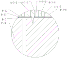
Fig. 5 is a schematic structural diagram of a joint between a flexible material adsorption cold-cutting system and a flexible glue-spraying cutting panel in a low-temperature cutting device for a flexible resilient material.
Fig. 6 is a front view of a cold-cutting blade head module in a cold-cutting apparatus for flexible resilient material.
Fig. 7 is a B-B cross-sectional view of a cold cutter head module in a cold cutter apparatus for flexible resilient material.
In the figure: 1. an X-direction servo motor; 2. a motor bracket; 3. a general support; 4. the flexible material adsorbs and cools the cutting system; 5. a synchronous pulley; 6. an X guide rail; 7. a Y-direction servo motor; 8. a Y-direction displacement mechanism; 9. a Z-direction displacement mechanism; 4-1, a transmission shaft; 4-2, a transmission net belt; 4-3, cooling the cutter head module; 4-4, a liquid nitrogen conveying pipe; 4-5, a liquid nitrogen output pipe; 4-6, driven gear; 4-7, a driving gear; 4-8, servo motor; 4-9, a water circulation cooling exchanger; 4-10, cooling water pipes; 4-11, cutting the panel by flexible glue spraying; 4-12, flexibly rebounding the material to be cut; 4-13, sticking mucus; 4-3-1, a needle saw bit; 4-3-2, lubricating copper bush; 4-3-3, reciprocating cutter blocks; 4-3-4, a thermal insulation layer; 4-3-5, brass cooling temperature-transmitting blocks; 4-3-6, fixing the shell; 4-3-7, a liquid nitrogen control valve; 4-3-8, a liquid nitrogen pipe; 4-3-9, a linear reciprocating servo motor.
Detailed Description
The preferred embodiments of the present invention will be described below with reference to the accompanying drawings, it being understood that the preferred embodiments described herein are for illustration and explanation of the present invention only, and are not intended to limit the present invention.
It should be noted that the positional or positional relationship indicated by the terms such as "center", "upper", "lower", "left", "right", "vertical", "horizontal", "inner", "outer", etc. are based on the positional or positional relationship shown in the drawings, are merely for convenience of describing the present invention and simplifying the description, and do not indicate or imply that the apparatus or element to be referred to must have a specific orientation, be constructed and operated in a specific orientation, and thus should not be construed as limiting the present invention.
Referring to fig. 1-7, a low temperature cutting device for flexible resilient materials includes a general support 3, wherein an X-direction conveying assembly is arranged on the general support 3, a Y-direction displacement mechanism 8 is connected to the X-direction conveying assembly, the Y-direction displacement mechanism 8 is connected to a Y-direction servo motor 7, and the Y-direction displacement mechanism 8 is connected to a Z-direction displacement mechanism 9;
the flexible material adsorption cooling cutting system 4 comprises a transmission net belt 4-2, transmission shafts 4-1 are arranged at two ends in the transmission net belt 4-2, a cooling cutting tool bit module 4-3 is arranged above the transmission net belt 4-2, the cooling cutting tool bit module 4-3 is connected with a Z-direction displacement mechanism 9, the cooling cutting tool bit module 4-3 is connected with a cooling component, the inner side of the transmission net belt 4-2 is connected with a flexible glue spraying cutting panel 4-11, and a flexible rebound material 4-12 to be cut is arranged above the transmission net belt 4-2;
the lower end of the reticular conveying net belt is directly contacted with the cuboid plane type flexible glue spraying cutting panel 4-11 and dragged on the flexible glue spraying cutting panel, the bonding mucus 4-13 is sprayed out of the meshes on the front surface of the flexible glue spraying cutting panel 4-11 by a pump, and the flexible rebound material 4-12 placed on the conveying net belt is tightly bonded with the conveying net belt by matching with a smoothing plate brush.
The cooling cutting tool bit module 4-3 comprises a fixed shell 4-3-6, the fixed shell 4-3-6 is fixedly connected with a Z-direction displacement mechanism 9, a linear reciprocating servo motor 4-3-9 is fixedly connected in the fixed shell 4-3-6, and the output end of the linear reciprocating servo motor 4-3-9 is fixedly connected with a needle saw tool bit 4-3-1.
One side of the overall support 3 is provided with a motor support 2, the top end of the motor support 2 is fixedly connected with an X-direction servo motor 1, an X-direction conveying assembly comprises two synchronous pulleys 5 which are respectively arranged at two ends of one side of the overall support 3, the two synchronous pulleys 5 are in transmission connection through a synchronous belt, an output shaft of the X-direction servo motor 1 is coaxially and fixedly connected with the synchronous pulleys 5, and an X guide rail 6 is arranged between the two synchronous pulleys 5.
The conveying motor 4-8 is arranged on the overall support 3, the output of the conveying motor 4-8 is coaxially and fixedly connected with the driving gear 4-7, the driven gear 4-6 is fixedly connected with the outside of the transmission shaft 4-1, and the driving gear 4-7 is in meshed connection with the driven gear 4-6.
The cooling assembly comprises a water circulation cooling exchanger 4-9 arranged on one side of the overall support 3, the water circulation cooling exchanger 4-9 is connected with a cooling water pipe 4-10, a liquid nitrogen conveying pipe 4-4 and a liquid nitrogen output pipe 4-5, and the liquid nitrogen conveying pipe 4-4 and the liquid nitrogen output pipe 4-5 are connected with the cooling cutting tool bit module 4-3.
And an adhesive bonding liquid 4-13 is arranged between the flexible adhesive spraying cutting panel 4-11 and the transmission net belt 4-2.
The flexible glue-spraying cutting panel 4-11 is made of flexible polyurethane.
The outside of the needle saw bit 4-3-1 is fixedly provided with a lubrication copper sleeve 4-3-2, and a plurality of reciprocating cutter blocks 4-3-3 are connected to the lubrication copper sleeve 4-3-2.
The fixed shell 4-3-6 is internally and fixedly connected with the reciprocating cutter block 4-3-3, the outer sleeve of the needle saw cutter head 4-3-1 is slidably provided with the lubricating copper sleeve 4-3-2, the lubricating copper sleeve 4-3-2 is fixedly connected with the reciprocating cutter block 4-3-3, the brass cooling temperature transmission block 4-3-5 is arranged between the reciprocating cutter block 4-3-3 and the fixed shell 4-3-6, and the heat insulation layer 4-3-4 is arranged between the brass cooling temperature transmission block 4-3-5 and the reciprocating cutter block 4-3-3.
The top end in the fixed shell 4-3-6 is fixedly connected with a liquid nitrogen control valve 4-3-7, and the liquid nitrogen control valve 4-3-7 is matched and connected with a liquid nitrogen conveying pipe 4-4 and a liquid nitrogen output pipe 4-5 to realize the supply control of liquid nitrogen.
The brass cooling temperature-transmitting block 4-3-5 is characterized in that connecting holes are formed in two sides of the brass cooling temperature-transmitting block, the connecting holes are connected with liquid nitrogen pipes 4-3-8, two liquid nitrogen pipes 4-3-8 are arranged, one liquid nitrogen pipe 4-3-8 is connected with a liquid nitrogen conveying pipe 4-4, and the other liquid nitrogen pipe 4-3-8 is connected with a liquid nitrogen control valve 4-3-7.
The upper end of the cooling cutting tool bit module 4-3 is supplied with cooling liquid nitrogen through a liquid nitrogen conveying pipe 4-4, a liquid nitrogen output pipe 4-5 and a water circulation cooling exchanger 4-9 arranged on the right side of the cooling cutting tool bit module. The brass cooling temperature transmission block 4-3-5 is provided with a round hole at the center, a cylindrical heat insulation layer 4-3-4 with an upper flange is sleeved outside-in sequence to realize temperature insulation between the brass cooling temperature transmission block and the reciprocating cutter block 4-3, then the center of the reciprocating cutter block 4-3 with a lower end being a cylindrical cylinder and an upper part being a cuboid is provided with a round hole, a lubrication channel is fixedly arranged in the round hole, so that movement lubrication of the needle saw cutter head 4-3-1 is realized, and the needle saw cutter head 4-3-1 is controlled by a linear reciprocating servo motor 4-3-9 to realize vertical reciprocating movement of the needle saw cutter head 4-3-1.
Finally, it should be noted that: the foregoing description is only a preferred embodiment of the present invention, and the present invention is not limited thereto, but it is to be understood that modifications and equivalents of some of the technical features described in the foregoing embodiments may be made by those skilled in the art, although the present invention has been described in detail with reference to the foregoing embodiments.
Claims (10)
1. The low-temperature cutting equipment for the flexible rebound material comprises a general support and is characterized in that an X-direction conveying assembly is arranged on the general support, a Y-direction displacement mechanism is connected to the X-direction conveying assembly, and the Y-direction displacement mechanism is connected with a Z-direction displacement mechanism;
the flexible material adsorption cooling cutting system comprises a transmission net belt, transmission shafts are arranged at two ends in the transmission net belt, a cooling cutting tool bit module is arranged above the transmission net belt and connected with a Z-direction displacement mechanism, the cooling cutting tool bit module is connected with a cooling assembly, the inner side of the transmission net belt is connected with a flexible glue spraying cutting panel, and a flexible rebound material to be cut is arranged above the transmission net belt;
the cooling cutting tool bit module comprises a fixed shell, wherein the fixed shell is fixedly connected with the Z-direction displacement mechanism, a linear reciprocating servo motor is fixedly connected in the fixed shell, and the output end of the linear reciprocating servo motor is fixedly connected with a needle saw tool bit.
2. The low-temperature cutting device for flexible rebound materials according to claim 1, wherein a motor support is arranged on one side of the overall support, the top end of the motor support is fixedly connected with an X-direction servo motor, the X-direction conveying assembly comprises two synchronous pulleys respectively arranged at two ends of one side of the overall support, the two synchronous pulleys are in transmission connection through a synchronous belt, an output shaft of the X-direction servo motor is fixedly connected with the synchronous pulleys coaxially, and an X guide rail is arranged between the two synchronous pulleys.
3. The cryogenic cutting apparatus for flexible resilient material of claim 1, wherein the overall support is mounted with a conveyor motor, the output of the conveyor motor being fixedly connected coaxially with a drive gear, the exterior of the drive shaft being fixedly connected with a driven gear, the drive gear being in meshed connection with the driven gear.
4. The cryocutting apparatus for flexible resilient material of claim 1, wherein the cooling assembly comprises a water circulation cooling switch disposed on one side of the overall support, the water circulation cooling switch being connected to a cooling water pipe, a liquid nitrogen delivery pipe, and a liquid nitrogen delivery pipe, both of which are connected to the cooling cutting bit module.
5. The cryogenic cutting apparatus for flexible resilient material of claim 1, wherein an adhesive is provided between the flexible adhesive-sprayed cutting panel and the drive belt.
6. The cryogenic cutting apparatus for flexible resilient material of claim 5, wherein the flexible glue-jet cutting panel is made of flexible polyurethane.
7. The cryogenic cutting apparatus for flexible resilient material of claim 4, wherein the exterior of the needle saw bit is fixedly provided with a lubricating copper sleeve to which a plurality of reciprocating cutter blocks are attached.
8. The cryogenic cutting apparatus for flexible resilient material of claim 7, wherein the stationary housing is fixedly coupled to a reciprocating cutter block, the outer sleeve of the needle saw bit is slidably provided with a lubricating copper sleeve fixedly coupled to the reciprocating cutter block, a brass cooling temperature block is disposed between the reciprocating cutter block and the stationary housing, and a thermal barrier is disposed between the brass cooling temperature block and the reciprocating cutter block.
9. The cryocutting apparatus for flexible resilient material of claim 8 wherein the top end within the stationary housing is fixedly connected to a liquid nitrogen control valve, the liquid nitrogen control valve being cooperatively connected to a liquid nitrogen delivery tube and a liquid nitrogen delivery tube.
10. The cryocutting apparatus for flexible resilient material of claim 9 wherein the brass cooling temperature transfer block has connecting holes on both sides, the connecting holes being connected with liquid nitrogen tubes, the liquid nitrogen tubes having two, one of the liquid nitrogen tubes being connected with a liquid nitrogen delivery tube and the other liquid nitrogen tube being connected with a liquid nitrogen control valve.
Priority Applications (1)
| Application Number | Priority Date | Filing Date | Title |
|---|---|---|---|
| CN202110984942.8A CN113681601B (en) | 2021-08-26 | 2021-08-26 | Low-temperature cutting equipment for flexible rebound material |
Applications Claiming Priority (1)
| Application Number | Priority Date | Filing Date | Title |
|---|---|---|---|
| CN202110984942.8A CN113681601B (en) | 2021-08-26 | 2021-08-26 | Low-temperature cutting equipment for flexible rebound material |
Publications (2)
| Publication Number | Publication Date |
|---|---|
| CN113681601A CN113681601A (en) | 2021-11-23 |
| CN113681601B true CN113681601B (en) | 2023-05-23 |
Family
ID=78582695
Family Applications (1)
| Application Number | Title | Priority Date | Filing Date |
|---|---|---|---|
| CN202110984942.8A Active CN113681601B (en) | 2021-08-26 | 2021-08-26 | Low-temperature cutting equipment for flexible rebound material |
Country Status (1)
| Country | Link |
|---|---|
| CN (1) | CN113681601B (en) |
Families Citing this family (5)
| Publication number | Priority date | Publication date | Assignee | Title |
|---|---|---|---|---|
| CN114536437B (en) * | 2022-03-04 | 2025-07-01 | 上海百琪迈科技(集团)有限公司 | A device for cutting special-shaped flexible materials with anti-shake function |
| CN114559481B (en) * | 2022-03-04 | 2025-06-17 | 上海百琪迈科技(集团)有限公司 | Device is tailor to anti-shock dysmorphism flexible material |
| CN114594727B (en) * | 2022-03-04 | 2023-10-24 | 上海百琪迈科技(集团)有限公司 | Height self-adaptive feedback control system for special-shaped flexible material |
| CN114407110B (en) * | 2022-03-04 | 2025-06-20 | 上海百琪迈科技(集团)有限公司 | Cutting device and control system for special-shaped flexible materials based on light reflection jitter detection and suppression |
| CN114625185B (en) * | 2022-03-04 | 2024-01-26 | 上海百琪迈科技(集团)有限公司 | Control device for cutting special-shaped flexible material based on capacitance displacement detection vibration suppression |
Family Cites Families (5)
| Publication number | Priority date | Publication date | Assignee | Title |
|---|---|---|---|---|
| JPH0985737A (en) * | 1995-09-22 | 1997-03-31 | Toray Eng Co Ltd | Wire type cutting device |
| CN203391436U (en) * | 2013-07-22 | 2014-01-15 | 稳健实业(深圳)有限公司 | Manufacturing equipment of surgical instrument platform casing |
| CN210551581U (en) * | 2019-06-17 | 2020-05-19 | 扬州哈工博视科技有限公司 | Flexible material cutting equipment |
| CN212553960U (en) * | 2020-05-13 | 2021-02-19 | 苏州奥莱多姆精密配件有限公司 | Rubber and plastic product cooling cutting device |
| CN112091449B (en) * | 2020-09-15 | 2022-03-08 | 溆浦县顺成服装有限公司 | Laser cloth cutting equipment |
-
2021
- 2021-08-26 CN CN202110984942.8A patent/CN113681601B/en active Active
Also Published As
| Publication number | Publication date |
|---|---|
| CN113681601A (en) | 2021-11-23 |
Similar Documents
| Publication | Publication Date | Title |
|---|---|---|
| CN113681601B (en) | Low-temperature cutting equipment for flexible rebound material | |
| CN220698574U (en) | Exchange table laser cutting machine with cooling and heat dissipation functions | |
| US10821402B2 (en) | Automatic arranging machine for membrane fiber and membrane module production device thereof | |
| CN113695762A (en) | Automatic focusing intelligent laser cutting equipment | |
| CN219684283U (en) | Automatic laser drilling machine for glass | |
| CN110340426B (en) | Chipless cutting and stretch-breaking device for metal flat tube and use method of chipless cutting and stretch-breaking device | |
| CN209613881U (en) | A kind of full-automatic Snake-Shaped Tube Bending Machine | |
| CN114850282A (en) | Battery pole piece winding and cutting device | |
| CN117644392B (en) | Metal pipe fitting welding set | |
| CN113580258B (en) | Quick automatic punching machine for plastic pipes | |
| CN209930632U (en) | Circuit board film sticking machine | |
| CN208289140U (en) | Scribing machine cooling structure and double-pole are without Water Cutting scribing machine | |
| KR101628741B1 (en) | The Forming Unit for Connection Part of Al-tube | |
| CN212669980U (en) | Carbon fiber flat preform needling machine | |
| CN219227986U (en) | Circuit board loading attachment for SMT chip mounter | |
| CN205651435U (en) | High -frequency vibration sponge ni zhifu drill system hole workstation | |
| CN216781201U (en) | Annular forced circulation main shaft cooling device with multiple nozzles | |
| CN110281287A (en) | A kind of miniature portable closing absorption type gasket numerical control cutting machine | |
| CN210553074U (en) | Welding device capable of rapidly replacing welding die | |
| CN209380883U (en) | Perforating device is used in a kind of automotive battery plastic housing production | |
| CN108941767A (en) | Scribing machine cooling structure and its application method and double-pole are without Water Cutting scribing machine and its cool-down method | |
| CN221211862U (en) | Heat abstractor of cutting machine | |
| CN212495920U (en) | Steel plate clamping support frame for numerical control plasma cutting | |
| CN220260366U (en) | Machining equipment cooled by ultralow-temperature air cooled air | |
| CN215280190U (en) | High accuracy is centre bore positioner for gear machining |
Legal Events
| Date | Code | Title | Description |
|---|---|---|---|
| PB01 | Publication | ||
| PB01 | Publication | ||
| SE01 | Entry into force of request for substantive examination | ||
| SE01 | Entry into force of request for substantive examination | ||
| GR01 | Patent grant | ||
| GR01 | Patent grant |