CN113681291A - Stainless steel coil plate edge rolling welding machine - Google Patents
Stainless steel coil plate edge rolling welding machine Download PDFInfo
- Publication number
- CN113681291A CN113681291A CN202110899026.4A CN202110899026A CN113681291A CN 113681291 A CN113681291 A CN 113681291A CN 202110899026 A CN202110899026 A CN 202110899026A CN 113681291 A CN113681291 A CN 113681291A
- Authority
- CN
- China
- Prior art keywords
- welding
- face
- rolling
- motor
- right end
- Prior art date
- Legal status (The legal status is an assumption and is not a legal conclusion. Google has not performed a legal analysis and makes no representation as to the accuracy of the status listed.)
- Granted
Links
- 238000003466 welding Methods 0.000 title claims abstract description 95
- 238000005096 rolling process Methods 0.000 title claims abstract description 59
- 229910001220 stainless steel Inorganic materials 0.000 title claims abstract description 19
- 239000010935 stainless steel Substances 0.000 title claims abstract description 19
- 238000009434 installation Methods 0.000 claims abstract description 39
- 238000001514 detection method Methods 0.000 claims abstract description 17
- 230000007246 mechanism Effects 0.000 claims description 22
- 238000009826 distribution Methods 0.000 claims 1
- 238000000034 method Methods 0.000 abstract description 7
- 238000004519 manufacturing process Methods 0.000 abstract description 6
- 230000008569 process Effects 0.000 abstract description 3
- 230000009286 beneficial effect Effects 0.000 description 2
- 238000003754 machining Methods 0.000 description 2
- 230000003139 buffering effect Effects 0.000 description 1
- 230000008859 change Effects 0.000 description 1
- 230000007547 defect Effects 0.000 description 1
- 238000010586 diagram Methods 0.000 description 1
- 230000000694 effects Effects 0.000 description 1
- 238000009499 grossing Methods 0.000 description 1
- 230000001771 impaired effect Effects 0.000 description 1
- 238000010030 laminating Methods 0.000 description 1
- 238000012986 modification Methods 0.000 description 1
- 230000004048 modification Effects 0.000 description 1
Images

Classifications
-
- B—PERFORMING OPERATIONS; TRANSPORTING
- B23—MACHINE TOOLS; METAL-WORKING NOT OTHERWISE PROVIDED FOR
- B23P—METAL-WORKING NOT OTHERWISE PROVIDED FOR; COMBINED OPERATIONS; UNIVERSAL MACHINE TOOLS
- B23P23/00—Machines or arrangements of machines for performing specified combinations of different metal-working operations not covered by a single other subclass
-
- B—PERFORMING OPERATIONS; TRANSPORTING
- B23—MACHINE TOOLS; METAL-WORKING NOT OTHERWISE PROVIDED FOR
- B23Q—DETAILS, COMPONENTS, OR ACCESSORIES FOR MACHINE TOOLS, e.g. ARRANGEMENTS FOR COPYING OR CONTROLLING; MACHINE TOOLS IN GENERAL CHARACTERISED BY THE CONSTRUCTION OF PARTICULAR DETAILS OR COMPONENTS; COMBINATIONS OR ASSOCIATIONS OF METAL-WORKING MACHINES, NOT DIRECTED TO A PARTICULAR RESULT
- B23Q17/00—Arrangements for observing, indicating or measuring on machine tools
-
- Y—GENERAL TAGGING OF NEW TECHNOLOGICAL DEVELOPMENTS; GENERAL TAGGING OF CROSS-SECTIONAL TECHNOLOGIES SPANNING OVER SEVERAL SECTIONS OF THE IPC; TECHNICAL SUBJECTS COVERED BY FORMER USPC CROSS-REFERENCE ART COLLECTIONS [XRACs] AND DIGESTS
- Y02—TECHNOLOGIES OR APPLICATIONS FOR MITIGATION OR ADAPTATION AGAINST CLIMATE CHANGE
- Y02P—CLIMATE CHANGE MITIGATION TECHNOLOGIES IN THE PRODUCTION OR PROCESSING OF GOODS
- Y02P70/00—Climate change mitigation technologies in the production process for final industrial or consumer products
- Y02P70/10—Greenhouse gas [GHG] capture, material saving, heat recovery or other energy efficient measures, e.g. motor control, characterised by manufacturing processes, e.g. for rolling metal or metal working
Landscapes
- Engineering & Computer Science (AREA)
- Mechanical Engineering (AREA)
- Physics & Mathematics (AREA)
- Optics & Photonics (AREA)
- Metal Rolling (AREA)
- Butt Welding And Welding Of Specific Article (AREA)
Abstract
The invention discloses a stainless steel coil rolling welding machine which comprises a shell, wherein an installation block is arranged in the shell, an installation cavity is arranged in the right end face of the installation block, an installation rotary table is arranged in the installation cavity in a sliding manner, twelve shrinking sliding grooves distributed in an array manner are arranged in the right end face of the installation rotary table, and a movable installation block is arranged in the shrinking sliding grooves in a sliding manner; the invention utilizes the self resilience of the rolled plate to enable the rolled plate to be tightly attached to the limiting column, so that the formed circle has higher roundness and is not limited by the diameter of the rolled plate any more, the time for replacing a clamp is saved, and the surface quality of the rolled plate is judged by whether the contact block arranged on the limiting column rotates or not, so that the detection on the surface quality of the rolled plate can be simultaneously completed in the process of rolling, the time for independent detection is saved, and the production efficiency is improved.
Description
Technical Field
The invention relates to the technical field of machining, in particular to a stainless steel coil rolling welding machine.
Background
Stainless steel coil plate is going to actual production and is going to need to detect its surface detection, prevent to cause the damage at the surface because of carrying and handling in-process, and influence the quality of finished product, and in carrying out the testing process to its surface, often can't carry out other operations, the efficiency is relatively poor, and carry out the edge rolling in-process to stainless steel coil plate, often because of stainless steel self's resilience, make often there is the clearance behind the edge rolling, this leads to in welding operation afterwards, need use specific anchor clamps or manual press the roll board, make the head and the tail both sides laminating of roll board, just can weld, and this part that can lead to having edge rolling warp because of the atress is uneven, make the circularity impaired, and the change to anchor clamps or the manual pressure still can influence production efficiency.
Disclosure of Invention
The invention aims to provide a stainless steel coil rolling welding machine which is used for overcoming the defects in the prior art.
The stainless steel coil edge rolling welding machine comprises a shell, wherein an installation block is arranged in the shell, an installation cavity is arranged in the right end face of the installation block, an installation rotary table is arranged in the installation cavity in a sliding manner, twelve shrinking sliding grooves distributed in an array manner are arranged in the right end face of the installation rotary table, a movable installation block is arranged in the shrinking sliding grooves in a sliding manner, a lead screw is connected to the movable installation block in a threaded manner, the inner end face of the lead screw is rotatably connected to the inner wall of the shrinking sliding grooves, the outer end face of the lead screw penetrates through the installation rotary table and extends into the installation cavity, a fixed rod is fixed on the right end face of the movable installation block and penetrates through a guide plate fixedly arranged on the inner wall of the shell, a guide sliding groove is formed in the guide plate, the fixed rod is arranged in the guide sliding groove, and a surface detection mechanism capable of detecting the surface quality of a coil is arranged on the fixed rod, the rolling mechanism capable of controlling the moving installation block to move is arranged in the installation cavity, a central motor is fixedly arranged in the right end face of the installation block, the right end face of the central motor is in driving connection with a welding installation shaft, and a welding mechanism used for welding a rolled plate is fixedly arranged on the welding installation shaft.
According to the technical scheme, the rounding mechanism comprises a gear ring which is arranged in the installation cavity in a sliding mode, the gear ring is not connected with the installation turntable, a bevel gear is fixedly connected to the outer end face of the screw rod and meshed with the gear ring, a rounding motor is fixedly arranged on the right end face of the shell, a rounding driving shaft is connected to the left end face of the rounding motor in a driving mode, the rounding driving shaft penetrates through the shell and is rotatably connected to the left end face of the cavity, the cavity is formed in the shell, a rounding power wheel is fixedly connected to the rounding driving shaft and meshed with the side wall of the gear ring, and the rounding mechanism utilizes resilience of a rolling plate, so that the forming roundness is higher and cannot deform due to unbalanced stress.
According to the technical scheme, the welding mechanism comprises a welding motor fixedly arranged in a welding installation shaft, a welding chute is formed in the inner wall of the right side of the welding motor, a welding moving block is arranged on the welding chute in a sliding mode, a welding lead screw is connected to the welding moving block in a threaded mode, the right end face of the welding lead screw is connected to the inner wall of the right side of the welding chute in a rotating mode, the left end face of the welding lead screw penetrates through the welding installation shaft and is connected to the right end face of the welding motor in a driving mode, a laser welding head and an infrared range finder are fixedly arranged on the upper end face of the welding moving block, and therefore the welding position can be accurately confirmed, and the welding effect is better.
In a further technical scheme, the surface detection mechanism comprises a limit column which is rotatably arranged on the surface of the fixed rod, an arc-shaped groove is arranged in the limiting column, a contact switch is fixedly arranged on the left end surface of the arc-shaped groove, the fixed rod is fixedly connected with a connecting block which is arranged in the arc-shaped groove, the outer end surface of the limiting column is fixedly connected with six buffer springs distributed in an array manner, a contact ring plate is fixedly connected with the outer end face of the buffer spring, a buffer cavity is arranged between the contact ring plate and the limiting post, an indicator lamp is fixedly arranged on the right end face of the contact ring plate, the surface detection mechanism judges the surface quality of the rolled plate according to the friction force between the contact ring plates which are tightly contacted with the surface of the rolled plate, the quality of the surface of the rolled plate can be detected simultaneously in the rolling process, so that the time for independent detection is saved, and the production efficiency is improved.
According to the further technical scheme, when the rolling motor is started to have obvious resistance, the rolling motor is disconnected.
According to a further technical scheme, the surface of the contact ring plate is subjected to smoothing treatment.
The invention has the beneficial effects that: according to the invention, the rebound resilience of the coil plate is utilized, so that the coil plate is tightly attached to the limiting column, the formed circle has higher roundness and is not limited by the diameter of the coil, and the time for replacing the clamp is saved;
the invention judges the surface quality of the rolled plate by judging whether the contact block arranged on the limiting column rotates or not, so that the detection of the surface quality of the rolled plate can be simultaneously finished in the rolling process, the time of independent detection is saved, and the production efficiency is improved.
Drawings
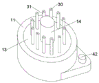
FIG. 1 is a schematic external view of the present invention;
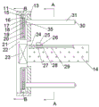
FIG. 2 is a schematic view of the overall structure of a stainless steel coil rounding welding machine according to the present invention;
FIG. 3 is a schematic view of A-A of FIG. 2 in accordance with the present invention;
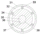
FIG. 4 is a block diagram of the surface sensing mechanism of FIG. 3 in accordance with the present invention;
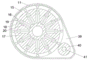
FIG. 5 is a schematic view of B-B of FIG. 2 according to the present invention.
Detailed Description
For purposes of making the objects and advantages of the present invention more apparent, the following detailed description of the invention, taken in conjunction with the examples, should be understood that the following text is only intended to describe one stainless steel coil edge bonding machine or several specific embodiments of the invention, and is not intended to strictly limit the scope of the invention as specifically claimed, as used herein, the terms upper, lower, left and right are not limited to their strict geometric definitions, but rather include tolerances for machining or human error rationality and inconsistencies, the following detailed description of which is specific:
referring to the attached drawings, the stainless steel coil rolling welding machine according to the embodiment of the invention comprises a housing 11, a mounting block 22 is arranged in the housing 11, a mounting cavity 21 is arranged in the right end face of the mounting block 22, a mounting rotary table 17 is slidably arranged in the mounting cavity 21, twelve reducing sliding grooves 20 distributed in an array are arranged in the right end face of the mounting rotary table 17, a movable mounting block 18 is slidably arranged in the reducing sliding grooves 20, a lead screw 19 is connected to the movable mounting block 18 through a thread, the inner end face of the lead screw 19 is rotatably connected to the inner wall of the reducing sliding groove 20, the outer end face of the lead screw 19 penetrates through the mounting rotary table 17 and extends into the mounting cavity 21, a fixing rod 35 is fixed on the right end face of the movable mounting block 18, the fixing rod 35 penetrates through a guide plate 13 fixedly arranged on the inner wall of the housing 11, and a guide sliding groove 12 is arranged on the guide plate 13, dead lever 35 sets up in the direction spout 12, be equipped with the surface detection mechanism 45 that can detect roll board surface quality on dead lever 35, be equipped with in the installation cavity 21 and control move the edge rolling mechanism 43 that installation piece 18 removed, the right-hand member face internal fixation of installation piece 22 is equipped with central motor 23, the right-hand member face drive of central motor 23 is connected with welding installation axle 14, the fixed welding mechanism 44 that is used for carrying out the welding with the roll board that is equipped with on welding installation axle 14.
Advantageously or exemplarily, the rounding mechanism 43 comprises a gear ring 15 slidably disposed in the mounting cavity 21, the gear ring 15 is not connected to the mounting turntable 17, a bevel gear 16 is fixedly connected to the outer end surface of the screw rod 19, the bevel gear 16 is engaged with the gear ring 15, a rounding motor 42 is fixedly disposed on the right end surface of the housing 11, a rounding driving shaft 41 is drivingly connected to the left end surface of the rounding motor 42, the rounding driving shaft 41 penetrates through the housing 11 and is rotatably connected to the left end surface of the cavity 39, the cavity 39 is disposed on the housing 11, a rounding power wheel 40 is fixedly connected to the rounding driving shaft 41, the rounding power wheel 40 is engaged with the side wall of the gear ring 15, when the rounding motor 42 is activated, the rounding driving shaft 41 rotates the rounding power wheel 40, the rounding power wheel 40 rotates the bevel gear 16 via the gear ring 15, the bevel gear 16 drives the screw rod 19 to rotate, and the screw rod 19 drives the movable mounting block 18 to move.
Beneficially or exemplarily, the welding mechanism 44 includes a welding motor 24 fixedly disposed in the welding installation shaft 14, a welding chute 29 is disposed on a right inner wall of the welding motor 24, a welding moving block 27 is slidably disposed on the welding chute 29, a welding lead screw 28 is connected to the welding moving block 27 in a threaded manner, a right end face of the welding lead screw 28 is rotatably connected to the right inner wall of the welding chute 29, a left end face of the welding lead screw 28 penetrates through the welding installation shaft 14 and is drivingly connected to a right end face of the welding motor 24, a laser welding head 25 and an infrared distance meter 26 are fixedly disposed on an upper end face of the welding moving block 27, the laser welding head 25 is used for welding the rolled plate, the infrared distance meter 26 is used for detecting a head-to-tail connection of the rolled plate, when the rolling step is completed and the surface quality is detected to be qualified, the central motor 23 is started, the central motor 23 drives the welding installation shaft 14 to rotate, the infrared distance measuring instrument 26 is started at the same time, when the infrared distance measuring instrument 26 detects the head-tail connection of the rolled plate, the central motor 23 stops rotating, the welding motor 24 and the laser welding head 25 are started, the welding motor 24 drives the welding moving block 27 to move through the welding lead screw 28, and the laser welding head 25 welds the head-tail connection of the rolled plate.
Advantageously or exemplarily, the surface detection mechanism 45 includes a limiting post 34 rotatably disposed on the surface of the fixing rod 35, an arc-shaped groove 37 is disposed in the limiting post 34, a contact switch 36 is fixedly disposed on a left end surface of the arc-shaped groove 37, a connecting block 38 is fixedly connected to the fixing rod 35, the connecting block 38 is disposed in the arc-shaped groove 37, six buffer springs 33 distributed in an array are fixedly connected to an outer end surface of the limiting post 34, a contact ring plate 31 is fixedly connected to an outer end surface of the buffer springs 33, a buffer cavity 32 is disposed between the contact ring plate 31 and the limiting post 34, an indicator lamp 30 is fixedly disposed on a right end surface of the contact ring plate 31, the buffer springs 33 play a role of buffering to prevent the rolled plate from being deformed due to a force of resilience of the rolled plate when the rolled plate starts to roll round, if the roll board surface quality is qualified, frictional force between roll board and the contact ring plate 31 will unable drive the contact ring plate 31 and rotate, when roll board surface quality is unqualified, the frictional force between roll board and the contact ring plate 31 will increase, lead to at the in-process of edge rolling, the contact ring plate 31 also follows the rotation, make the contact ring plate 31 drive spacing post 34 through buffer spring 33 and rotate, spacing post 34 rotates and drives contact switch 36 and connecting block 38 contact, the pilot lamp 30 that corresponds lights, remind the operator that the surface quality of which position is has the problem.
Advantageously or exemplarily, the edge-rolling motor 42 will be switched off when a significant resistance is caused after the edge-rolling motor 42 is activated.
Advantageously or exemplarily, the surface of the contact ring plate 31 is smoothed.
The invention relates to a stainless steel coil plate edge rolling welding machine, which comprises the following working procedures:
the rolling plate is arranged in the middle of the contact ring plate 31, the rolling motor 42 is started, the rolling motor 42 drives the rolling driving shaft 41 to rotate, the rolling driving shaft 41 drives the rolling power wheel 40 to rotate, the rolling power wheel 40 drives the bevel gear 16 to rotate through the gear ring 15, the bevel gear 16 drives the screw rod 19 to rotate, the screw rod 19 drives the movable mounting block 18 to move, the movable mounting block 18 drives the fixed rod 35 to move, the fixed rod 35 moves along the guide chute 12, the diameter of the circle formed by the fixed rod 35 is gradually reduced, the head and the tail of the rolling plate are reduced and close, in the rolling process, the self resilience force of the rolling plate is utilized to enable the rolling plate to be tightly attached to the surface of the fixed rod 35, the rolling plate has higher roundness, when the head and the tail of the rolling plate are in contact, the rolling motor 42 feels obvious resistance, the rolling motor 42 is disconnected and explains that the rolling is completed, and in the rolling process, the surface detection mechanism 45 can detect the surface quality of the rolled plate, when the surface quality of the rolled plate is qualified, the friction force between the rolled plate and the contact ring plate 31 cannot drive the contact ring plate 31 to rotate, and when the surface quality of the rolled plate is unqualified, the friction force between the rolled plate and the contact ring plate 31 is increased, so that the contact ring plate 31 also rotates in the rounding process, the contact ring plate 31 drives the limit column 34 to rotate through the buffer spring 33, the limit column 34 rotates to drive the contact switch 36 to contact with the connecting block 38, and the corresponding indicator lamp 30 lights up to remind an operator of the position where the surface quality is problematic;
and finally, after the rolling step is completed, and when the surface quality detection is qualified, the central motor 23 is started, the central motor 23 drives the welding mounting shaft 14 to rotate, the infrared distance meter 26 is started simultaneously, when the infrared distance meter 26 detects the head-tail connection part of the rolled plate, the central motor 23 stops rotating, the welding motor 24 and the laser welding head 25 are started, the welding motor 24 drives the welding moving block 27 to move through the welding lead screw 28, and the laser welding head 25 welds the head-tail connection part of the rolled plate.
The invention has the beneficial effects that: according to the invention, the rebound resilience of the coil plate is utilized, so that the coil plate is tightly attached to the limiting column, the formed circle has higher roundness and is not limited by the diameter of the coil, and the time for replacing the clamp is saved;
the invention judges the surface quality of the rolled plate by judging whether the contact block arranged on the limiting column rotates or not, so that the detection of the surface quality of the rolled plate can be simultaneously finished in the rolling process, the time of independent detection is saved, and the production efficiency is improved.
The above description is only for the purpose of illustrating the preferred embodiments of the present invention and is not to be construed as limiting the present invention in any way, and it will be apparent to those skilled in the art that the above description of the present invention is provided for all such modifications, equivalents and alternatives.
Claims (6)
1. The utility model provides a stainless steel coil of strip edge rolling welding machine, includes the shell, its characterized in that: the mounting block is arranged in the shell, a mounting cavity is arranged in the right end face of the mounting block, a mounting rotary table is arranged in the mounting cavity in a sliding manner, twelve shrinking chutes distributed in an array manner are arranged in the right end face of the mounting rotary table, a movable mounting block is arranged in the shrinking chutes in a sliding manner, a screw rod is connected to the movable mounting block in a threaded manner, the inner end face of the screw rod is rotatably connected to the inner wall of the shrinking chute, the outer end face of the screw rod penetrates through the mounting rotary table and extends into the mounting cavity, a fixed rod is fixed on the right end face of the movable mounting block and penetrates through a guide plate fixedly arranged on the inner wall of the shell, a guide chute is arranged on the guide plate, the fixed rod is arranged in the guide chute, a surface detection mechanism capable of detecting the surface quality of a rolled plate is arranged on the fixed rod, and a rolling mechanism capable of controlling the movable mounting block to move is arranged in the mounting cavity, the welding device is characterized in that a central motor is fixedly arranged in the right end face of the mounting block, the right end face of the central motor is in driving connection with a welding mounting shaft, and a welding mechanism for welding the rolled plate is fixedly arranged on the welding mounting shaft.
2. The stainless steel coil rolling and welding machine of claim 1, characterized in that: the circle rolling mechanism comprises a gear ring arranged in the installation cavity in a sliding mode, the gear ring is not connected with the installation turntable, a bevel gear is fixedly connected to the outer end face of the screw rod and is meshed with the gear ring, a circle rolling motor is fixedly arranged on the right end face of the shell, a circle rolling driving shaft is connected to the left end face of the circle rolling motor in a driving mode, the circle rolling driving shaft penetrates through the shell and is rotatably connected to the left end face of the cavity, the cavity is arranged on the shell, a circle rolling power wheel is fixedly connected to the circle rolling driving shaft, and the circle rolling power wheel is meshed with the side wall of the gear ring.
3. The stainless steel coil rolling and welding machine of claim 1, characterized in that: the welding mechanism comprises a welding motor fixedly arranged in a welding installation shaft, a welding sliding groove is formed in the inner wall of the right side of the welding motor, a welding moving block is arranged on the welding sliding groove in a sliding mode, a welding lead screw is connected to the welding moving block in a threaded mode, the right end face of the welding lead screw is connected to the inner wall of the right side of the welding sliding groove in a rotating mode, the left end face of the welding lead screw penetrates through the welding installation shaft and is connected to the right end face of the welding motor in a driving mode, and a laser welding head and an infrared range finder are fixedly arranged on the upper end face of the welding moving block.
4. The stainless steel coil rolling and welding machine of claim 1, characterized in that: the surface detection mechanism sets up including rotating the spacing post on fixed rod surface, be equipped with the arc wall in the spacing post, the fixed contact switch that is equipped with on the left end face of arc wall, fixedly connected with connecting block on the dead lever, the connecting block sets up in the arc wall, the buffer spring of six array distributions of outer terminal surface fixedly connected with of spacing post, buffer spring's outer terminal surface fixedly connected with contact ring board, contact ring board with be equipped with the cushion chamber between the spacing post, the fixed pilot lamp that is equipped with of right-hand member face of contact ring board.
5. The stainless steel coil rolling and welding machine of claim 2, characterized in that: when the rolling motor is started to have obvious resistance, the rolling motor is disconnected.
6. The stainless steel coil rolling welding machine of claim 4, characterized in that: the surface of the contact ring plate is smoothed.
Priority Applications (1)
| Application Number | Priority Date | Filing Date | Title |
|---|---|---|---|
| CN202110899026.4A CN113681291B (en) | 2021-08-06 | 2021-08-06 | Stainless steel coil plate edge rolling welding machine |
Applications Claiming Priority (1)
| Application Number | Priority Date | Filing Date | Title |
|---|---|---|---|
| CN202110899026.4A CN113681291B (en) | 2021-08-06 | 2021-08-06 | Stainless steel coil plate edge rolling welding machine |
Publications (2)
| Publication Number | Publication Date |
|---|---|
| CN113681291A true CN113681291A (en) | 2021-11-23 |
| CN113681291B CN113681291B (en) | 2022-08-23 |
Family
ID=78578993
Family Applications (1)
| Application Number | Title | Priority Date | Filing Date |
|---|---|---|---|
| CN202110899026.4A Active CN113681291B (en) | 2021-08-06 | 2021-08-06 | Stainless steel coil plate edge rolling welding machine |
Country Status (1)
| Country | Link |
|---|---|
| CN (1) | CN113681291B (en) |
Citations (9)
| Publication number | Priority date | Publication date | Assignee | Title |
|---|---|---|---|---|
| US5531370A (en) * | 1990-08-14 | 1996-07-02 | Rohrberg; Roderick G. | High-precision sizing, cutting and welding tool system for specialty aerospace alloys |
| US5692421A (en) * | 1990-08-14 | 1997-12-02 | Rohrberg; Roderick G. | High-precision cutting tool system |
| US20060049180A1 (en) * | 2004-09-07 | 2006-03-09 | Franz Haimer | Apparatus for the clamping of a rotary tool in a tool holder |
| CN201140336Y (en) * | 2008-01-19 | 2008-10-29 | 李虎 | Multifunctional edge coil shaping apparatus |
| CN105026063A (en) * | 2014-02-13 | 2015-11-04 | 三菱日立制铁机械株式会社 | Production method for plate-bending hollow roll, plate-bending hollow roll, and device for steel plate production process |
| JP2019141887A (en) * | 2018-02-21 | 2019-08-29 | 光洋サーモシステム株式会社 | Caulking deformation amount setting method and manufacturing method of caulking coupling structure |
| CN111168285A (en) * | 2020-03-04 | 2020-05-19 | 李火城 | Welding leakage detection device and process of solar water heater water tank liner rounding welding machine |
| CN111922138A (en) * | 2020-07-29 | 2020-11-13 | 薛继纲 | Coiled plate forming process |
| CN212917072U (en) * | 2020-08-26 | 2021-04-09 | 河南恒通新材料有限公司 | High-efficient decoiler |
-
2021
- 2021-08-06 CN CN202110899026.4A patent/CN113681291B/en active Active
Patent Citations (9)
| Publication number | Priority date | Publication date | Assignee | Title |
|---|---|---|---|---|
| US5531370A (en) * | 1990-08-14 | 1996-07-02 | Rohrberg; Roderick G. | High-precision sizing, cutting and welding tool system for specialty aerospace alloys |
| US5692421A (en) * | 1990-08-14 | 1997-12-02 | Rohrberg; Roderick G. | High-precision cutting tool system |
| US20060049180A1 (en) * | 2004-09-07 | 2006-03-09 | Franz Haimer | Apparatus for the clamping of a rotary tool in a tool holder |
| CN201140336Y (en) * | 2008-01-19 | 2008-10-29 | 李虎 | Multifunctional edge coil shaping apparatus |
| CN105026063A (en) * | 2014-02-13 | 2015-11-04 | 三菱日立制铁机械株式会社 | Production method for plate-bending hollow roll, plate-bending hollow roll, and device for steel plate production process |
| JP2019141887A (en) * | 2018-02-21 | 2019-08-29 | 光洋サーモシステム株式会社 | Caulking deformation amount setting method and manufacturing method of caulking coupling structure |
| CN111168285A (en) * | 2020-03-04 | 2020-05-19 | 李火城 | Welding leakage detection device and process of solar water heater water tank liner rounding welding machine |
| CN111922138A (en) * | 2020-07-29 | 2020-11-13 | 薛继纲 | Coiled plate forming process |
| CN212917072U (en) * | 2020-08-26 | 2021-04-09 | 河南恒通新材料有限公司 | High-efficient decoiler |
Also Published As
| Publication number | Publication date |
|---|---|
| CN113681291B (en) | 2022-08-23 |
Similar Documents
| Publication | Publication Date | Title |
|---|---|---|
| CN102626855B (en) | Automatic torsion bar press fitting, measuring and straightening equipment | |
| US6118095A (en) | Control device for resistance welder | |
| CN202599444U (en) | In-wheel motor comprehensive parameter detection system | |
| CN113514191B (en) | Regulation type automobile tire dynamic balance detects machine | |
| CN216695541U (en) | Stamping sheet metal part detection device based on automobile parts | |
| CN103512736A (en) | Front brake testing device | |
| CN111307427A (en) | Device for detecting performance and durability of automobile tail plate | |
| CN115388741A (en) | Lead screw and rotation stopping disc jumping detection device | |
| CN215090366U (en) | Ribbed steel bar angle adjusting device based on laser displacement sensor | |
| CN113681291B (en) | Stainless steel coil plate edge rolling welding machine | |
| US10016835B2 (en) | Method for grinding electrode tip | |
| CN107687830A (en) | Differential gear pad selecting machine | |
| CN204188154U (en) | Automobile hub unit ring flange external diameter detection device | |
| CN212019722U (en) | Spot welding machine head | |
| CN117268218B (en) | Detection device and control method for differential mechanism shell of electric automobile | |
| CN218956091U (en) | Performance testing device of steering transmission shaft | |
| CN221303004U (en) | High-precision welding detection equipment | |
| US4899718A (en) | Apparatus for truing grinding wheel | |
| CN219607949U (en) | Online detection device for outer circle runout of brake | |
| CN208896004U (en) | A kind of flexible press device for motor and synchronous pulley | |
| JP2540095Y2 (en) | Crankshaft runout measuring device | |
| CN217452146U (en) | Special machine tool for ball head turning of ball head pin | |
| CN206677008U (en) | Improve the mould that punching part thrusts portion faces quality | |
| JP6236787B2 (en) | Eyeglass lens processing equipment | |
| CN211206108U (en) | Hardness detector for detecting standard sample |
Legal Events
| Date | Code | Title | Description |
|---|---|---|---|
| PB01 | Publication | ||
| PB01 | Publication | ||
| SE01 | Entry into force of request for substantive examination | ||
| SE01 | Entry into force of request for substantive examination | ||
| TA01 | Transfer of patent application right | ||
| TA01 | Transfer of patent application right |
Effective date of registration: 20220805 Address after: 410000 No. 29, Daming West Road, shaping street, Kaifu District, Changsha City, Hunan Province Applicant after: Hunan Shunxin metal products Technology Co.,Ltd. Address before: 310000 No. 65-3, Xintang Road, Jianggan District, Hangzhou City, Zhejiang Province Applicant before: Chen Guoying |
|
| GR01 | Patent grant | ||
| GR01 | Patent grant |