CN113681082A - Section bar cutting equipment - Google Patents
Section bar cutting equipment Download PDFInfo
- Publication number
- CN113681082A CN113681082A CN202110871426.4A CN202110871426A CN113681082A CN 113681082 A CN113681082 A CN 113681082A CN 202110871426 A CN202110871426 A CN 202110871426A CN 113681082 A CN113681082 A CN 113681082A
- Authority
- CN
- China
- Prior art keywords
- piston
- cylinder body
- hydraulic cylinder
- grading
- oil
- Prior art date
- Legal status (The legal status is an assumption and is not a legal conclusion. Google has not performed a legal analysis and makes no representation as to the accuracy of the status listed.)
- Withdrawn
Links
- 238000005520 cutting process Methods 0.000 title claims abstract description 51
- 239000003921 oil Substances 0.000 claims description 78
- 239000010720 hydraulic oil Substances 0.000 claims description 19
- 238000007789 sealing Methods 0.000 claims description 3
- 238000005265 energy consumption Methods 0.000 abstract description 10
- 230000008901 benefit Effects 0.000 abstract description 7
- 230000009471 action Effects 0.000 description 4
- 230000000712 assembly Effects 0.000 description 3
- 238000000429 assembly Methods 0.000 description 3
- 238000006073 displacement reaction Methods 0.000 description 3
- 230000007246 mechanism Effects 0.000 description 3
- 238000000034 method Methods 0.000 description 3
- 230000008569 process Effects 0.000 description 3
- 230000009286 beneficial effect Effects 0.000 description 2
- 238000004891 communication Methods 0.000 description 2
- 230000007423 decrease Effects 0.000 description 2
- 230000000694 effects Effects 0.000 description 2
- 238000009434 installation Methods 0.000 description 2
- 239000000463 material Substances 0.000 description 2
- 239000013589 supplement Substances 0.000 description 2
- 230000006835 compression Effects 0.000 description 1
- 238000007906 compression Methods 0.000 description 1
- 238000011161 development Methods 0.000 description 1
- 238000010586 diagram Methods 0.000 description 1
- 238000004519 manufacturing process Methods 0.000 description 1
- 238000012986 modification Methods 0.000 description 1
- 230000004048 modification Effects 0.000 description 1
- 238000012545 processing Methods 0.000 description 1
Images


Classifications
-
- B—PERFORMING OPERATIONS; TRANSPORTING
- B23—MACHINE TOOLS; METAL-WORKING NOT OTHERWISE PROVIDED FOR
- B23D—PLANING; SLOTTING; SHEARING; BROACHING; SAWING; FILING; SCRAPING; LIKE OPERATIONS FOR WORKING METAL BY REMOVING MATERIAL, NOT OTHERWISE PROVIDED FOR
- B23D79/00—Methods, machines, or devices not covered elsewhere, for working metal by removal of material
Landscapes
- Physics & Mathematics (AREA)
- Optics & Photonics (AREA)
- Engineering & Computer Science (AREA)
- Mechanical Engineering (AREA)
- Actuator (AREA)
Abstract
The invention discloses a section bar cutting device, which comprises a base; two ends of the top of the base are connected with mounting beams through upright posts; the two sides of the bottom of the mounting beam are connected with mounting plates through hydraulic cylinders; the bottom of the mounting plate is connected with a cutting tool; the hydraulic cylinder comprises a hydraulic cylinder body, a first piston and a grading cylinder; one end of the hydraulic cylinder body is connected with the mounting beam, and the other end of the hydraulic cylinder body is provided with a first opening; the first piston is connected in the hydraulic cylinder body in a sliding mode; the grading cylinder is arranged in the hydraulic cylinder body, one end of the grading cylinder is connected with the first piston, and the other end of the grading cylinder hermetically extends out of the hydraulic cylinder body through the first opening and is connected with the mounting plate; the section bar cutting equipment has the advantages of compact and reasonable structure, low energy consumption, high operation efficiency, and good economic benefit and popularization value.
Description
Technical Field
The invention relates to the technical field of profile processing, in particular to profile cutting equipment.
Background
With the rapid development of the door and window industry, the consumption of the section bar is larger and larger; the size of the section bar is long when the section bar leaves a factory, and the section bar needs to be cut according to actual requirements when doors and windows are manufactured and processed, but the existing cutting equipment has large energy consumption and general cutting effect and cannot meet the use requirements; in the cutting process, the thickness of the section is large, the power of the traditional cutting equipment is insufficient, the stable descending speed cannot be ensured, and the blade is easy to shake, so that burrs are generated and the cutting quality is influenced; meanwhile, the energy consumption of the existing section cutting equipment is large, so that the production cost is increased, and the fine management of enterprises is not facilitated.
Disclosure of Invention
Based on this, in order to solve the problem that the existing section bar cutting equipment has large energy consumption, the invention provides the section bar cutting equipment, and the specific technical scheme is as follows:
a profile cutting apparatus includes a base; two ends of the top of the base are connected with mounting beams through upright posts; the two sides of the bottom of the mounting beam are connected with mounting plates through hydraulic cylinders; the bottom of the mounting plate is connected with a cutting tool; the hydraulic cylinder comprises a hydraulic cylinder body, a first piston and a grading cylinder; one end of the hydraulic cylinder body is connected with the mounting beam, and the other end of the hydraulic cylinder body is provided with a first opening; the first piston is connected in the hydraulic cylinder body in a sliding mode; the grading cylinder is arranged in the hydraulic cylinder body, one end of the grading cylinder is connected with the first piston, and the other end of the grading cylinder hermetically extends out of the hydraulic cylinder body through the first opening and is connected with the mounting plate.
According to the sectional material cutting equipment, the grading cylinder is sleeved in the hydraulic cylinder body, so that the hydraulic cylinder and the grading cylinder can realize the function of quick lifting only by less hydraulic oil flowing, and the energy consumption is effectively reduced; the section cutting equipment has the advantages of compact and reasonable structure, low energy consumption, high operation efficiency and good economic benefit and popularization value.
Further, the classifying cylinder comprises a classifying cylinder body, a second piston and a piston rod; the second piston is connected in the grading cylinder body in a sliding mode; one end of the piston rod is fixedly connected with one end, far away from the first piston, of the second piston, and the other end of the piston rod hermetically extends out of the grading cylinder body and is connected with the mounting plate.
Furthermore, a first oil port and a second oil port for introducing hydraulic oil are formed in the side wall of the hydraulic cylinder body; the first oil port is positioned at one end of the hydraulic cylinder body close to the mounting beam; the second oil port is located at one end, close to the mounting plate, of the hydraulic cylinder body.
Furthermore, the hydraulic cylinder is externally connected with an oil tank; a first pipeline is arranged at one end of the oil tank, and a second pipeline is arranged at the other end of the oil tank; one end of the first pipeline is communicated with the oil tank, and the other end of the first pipeline is communicated with the hydraulic cylinder through the first oil port; one end of the second pipeline is communicated with the oil tank, and the other end of the second pipeline is communicated with the hydraulic cylinder through the second oil port.
Further, the second piston divides the classification cylinder body into a rod chamber and a rodless chamber; a first channel is formed in the side wall of the grading cylinder body; the rod cavity is communicated with the rodless cavity through the first channel.
Further, a second channel is formed in the periphery of the first piston; a third channel is formed in the side wall of the grading cylinder body; when the first piston moves to the maximum stroke position, one end of the second channel is butted with the second oil port, and the other end of the second channel is communicated with one end of the third channel; the other end of the third channel is communicated with the rodless cavity.
Further, the hydraulic cylinder also comprises a push plate and a push rod; the push plate is arranged in the hydraulic cylinder body and is positioned on one side of the first piston, which is far away from the piston rod; one end of the push rod is connected with the push plate, and the other end of the push rod penetrates through the first piston in a sealing mode and extends into the grading cylinder.
Further, the diameter of the push plate is larger than that of the second piston and smaller than that of the first piston.
Further, the grading cylinder also comprises a third piston and a baffle ring; the third piston and the baffle ring are both arranged in the grading cylinder body; the baffle ring is connected to one end, close to the first piston, of the grading cylinder body; the third piston is connected in the baffle ring in a sliding mode and is connected with one end, far away from the push plate, of the push rod.
Further, the grading cylinder further comprises a fourth piston; the fourth piston is slidably connected within the classification cylinder body and located between the third piston and the second piston; and a boosting assembly is arranged between the third piston and the fourth piston.
Drawings
The invention will be further understood from the following description in conjunction with the accompanying drawings. The components in the figures are not necessarily to scale, emphasis instead being placed upon illustrating the principles of the embodiments. Like reference numerals designate corresponding parts throughout the different views.
Fig. 1 is a schematic structural diagram of a profile cutting apparatus according to an embodiment of the present invention;
fig. 2 is one of schematic structural views of a hydraulic cylinder of a profile cutting apparatus according to one embodiment of the present invention;
FIG. 3 is an enlarged schematic view of the structure at A in FIG. 2;
FIG. 4 is a second schematic view of a hydraulic cylinder of a profile cutting apparatus according to one embodiment of the present invention;
FIG. 5 is an enlarged schematic view of the structure at B in FIG. 4;
FIG. 6 is an enlarged schematic view of the structure at C in FIG. 4;
FIG. 7 is a third schematic view showing the structure of a hydraulic cylinder of a profile cutting apparatus according to an embodiment of the present invention;
fig. 8 is a partial structural view of a hydraulic cylinder of a profile cutting apparatus according to an embodiment of the present invention.
Description of reference numerals: 1. a base; 2. a column; 3. mounting a beam; 4. a hydraulic cylinder; 41. a hydraulic cylinder body; 411. a first oil port; 412. a second oil port; 42. a first piston; 421. a second channel; 43. a grading cylinder; 431. a classification cylinder body; 4311. a first channel; 4312. a third channel; 432. a second piston; 433. a third piston; 434. a baffle ring; 435. a fourth piston; 436. a piston rod; 437. a force increasing component; 4371. a first crank; 4372. an arc-shaped hole; 4373. a second crank; 4374. a rotation pin; 4375. a third crank; 4376. a chute; 438. an airbag module; 4381. an inflator; 4382. an air bag; 44. pushing the plate; 45. a push rod; 5. an oil tank; 51. a first conduit; 52. a second conduit; 6. mounting a plate; 7. and (4) cutting the cutter.
Detailed Description
In order to make the objects, technical solutions and advantages of the present invention more apparent, the present invention is further described in detail below with reference to embodiments thereof. It should be understood that the detailed description and specific examples, while indicating the scope of the invention, are intended for purposes of illustration only and are not intended to limit the scope of the invention.
It will be understood that when an element is referred to as being "secured to" another element, it can be directly on the other element or intervening elements may also be present. When an element is referred to as being "connected" to another element, it can be directly connected to the other element or intervening elements may also be present. The terms "vertical," "horizontal," "left," "right," and the like as used herein are for illustrative purposes only and do not represent the only embodiments.
Unless defined otherwise, all technical and scientific terms used herein have the same meaning as commonly understood by one of ordinary skill in the art to which this invention belongs. The terminology used herein in the description of the invention is for the purpose of describing particular embodiments only and is not intended to be limiting of the invention. As used herein, the term "and/or" includes any and all combinations of one or more of the associated listed items.
The terms "first" and "second" used herein do not denote any particular order or quantity, but rather are used to distinguish one element from another.
As shown in fig. 1 to 8, a profile cutting apparatus according to an embodiment of the present invention includes a base 1; two ends of the top of the base 1 are connected with mounting beams 3 through upright posts 2; two sides of the bottom of the mounting beam 3 are connected with a mounting plate 6 through hydraulic cylinders 4, the bottom of the mounting plate 6 is connected with a cutting tool 7, and each hydraulic cylinder 4 comprises a hydraulic cylinder body 41, a first piston 42 and a grading cylinder 43; one end of the hydraulic cylinder body 41 is connected with the mounting beam 3, and the other end of the hydraulic cylinder body 41 is provided with a first opening; the first piston 42 is slidably connected in the hydraulic cylinder body 41; the classifying cylinder 43 is disposed in the hydraulic cylinder body 41, one end of the classifying cylinder 43 is connected to the first piston 42, and the other end of the classifying cylinder 43 extends out of the hydraulic cylinder body 41 through the first opening in a sealing manner and is connected to the mounting plate 6.
According to the sectional material cutting equipment, the grading cylinder 43 is sleeved in the hydraulic cylinder body 41, so that the hydraulic cylinder 4 and the grading cylinder 43 can be quickly lifted only by less hydraulic oil flowing, and the energy consumption is effectively reduced; the section cutting equipment has the advantages of compact and reasonable structure, low energy consumption, high operation efficiency and good economic benefit and popularization value.
Specifically, the first piston 42 is integrally formed with the classifying cylinder 43; the outer wall of the grading cylinder body 431 is abutted with the inner wall of the first opening; the classification cylinder 43 is hermetically movably connected in the hydraulic cylinder body 41 through the first opening; the hydraulic cylinder 4 and the classification cylinder 43 are filled with hydraulic oil.
In one embodiment, the staging cylinder 43 includes a staging cylinder body 431, a second piston 432, and a piston rod 436; the second piston 432 is slidably connected within the grading cylinder body 431; one end of the piston rod 436 is fixedly connected to one end of the second piston 432 away from the first piston 42, and the other end of the piston rod 436 sealingly extends out of the grading cylinder body 431 and is connected to the mounting plate 6.
Specifically, the second piston 432 is integrally formed with the piston rod 436; a second opening is formed at one end, far away from the first piston 42, of the grading cylinder body 431; the outer wall of the piston rod 436 abuts against the inner wall of the second opening; the piston rod 436 is hermetically movably connected in the grading cylinder body 431 through the second opening;
when the device is used, the first piston 42 drives the grading cylinder 43 to displace, and the grading cylinder 43 moves the cutting tool 7 through the mounting plate 6, so that the cutting tool 7 is lifted at one stage;
when the first piston 42 moves to the maximum stroke position, the second piston 432 drives the piston rod 436 to displace, and the piston rod 436 moves the cutting tool 7 through the mounting plate 6, so that the secondary lifting of the cutting tool 7 is realized;
through the arrangement, the oil return amount in the hydraulic cylinder body 41 and the grading cylinder body 431 is effectively reduced, so that the hydraulic cylinder 4 and the grading cylinder 43 can realize the function of quick lifting only by less hydraulic oil flowing, and the energy consumption is effectively reduced.
In one embodiment, the cross-sections of the cylinder body 41, the first piston 42, the stepped cylinder body 431, the second piston 432, and the piston rod 436 are all circular.
In one embodiment, the central axis of the hydraulic cylinder body 41, the central axis of the classifying cylinder body 431, the central axis of the first piston 42, the central axis of the second piston 432, and the central axis of the piston rod 436 all coincide.
In one embodiment, the diameter of the first piston 42 is greater than the diameter of the second piston 432.
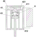
In one embodiment, a first oil port 411 and a second oil port 412 for introducing hydraulic oil are formed in the side wall of the hydraulic cylinder body 41; the first oil port 411 is located at one end of the hydraulic cylinder body 41 close to the mounting beam 3; the second oil port 412 is located at one end of the hydraulic cylinder body 41 close to the mounting plate 6.
Specifically, a containing cavity is arranged in the hydraulic cylinder body 41; the first piston 42 is arranged in the cavity and hermetically separates the cavity to form a first oil chamber and a second oil chamber; the first oil port 411 is arranged on the first oil chamber; the second oil port 412 is arranged on the second oil chamber; the classifying cylinder 43 is provided in the second oil chamber.
In one embodiment, a first slope is provided at one end of the hydraulic cylinder body 41 close to the piston rod 436; the first slope is arranged outwards from the central axis of the accommodating cavity.
Specifically, when the first piston 42 is displaced to one end of the hydraulic cylinder body 41 close to the piston rod 436, a certain gap is left between the first slope and the first piston 42, which is beneficial to oil supplement during return stroke.
In one embodiment, the hydraulic cylinder 4 is externally connected with an oil tank 5; a first pipeline 51 is arranged at one end of the oil tank 5, and a second pipeline 52 is arranged at the other end of the oil tank 5; one end of the first pipeline 51 is communicated with the oil tank 5, and the other end of the first pipeline 51 is communicated with the hydraulic cylinder 4 through the first oil port 411; one end of the second pipe 52 is communicated with the oil tank 5, and the other end of the second pipe 52 is communicated with the hydraulic cylinder 4 through the second oil port 412.
Specifically, the oil tank 5 is filled with hydraulic oil; the oil tank 5 is communicated with the first oil chamber through the first pipeline 51, and the oil tank 5 is communicated with the second oil chamber through the second pipeline 52.
In one embodiment, the second piston 432 divides the stepped cylinder body 431 into a rod chamber and a rodless chamber; a first channel 4311 is formed on the side wall of the grading cylinder body 431; the rod chamber is in communication with the rodless chamber through the first channel 4311.
Specifically, a cavity is arranged in the grading cylinder body 431; the second piston 432 is arranged in the cavity and hermetically separates the cavity to form the rod cavity and the rodless cavity; the piston rod 436 is disposed within the rod cavity.
In one embodiment, a second slope is provided at an end of the grading cylinder body 431 away from the first piston 42; the second slope is arranged outwards from the central axis of the cavity.
Specifically, when the second piston 432 is displaced to the end of the grading cylinder body 431 away from the first piston 42, a certain gap is left between the second slope and the second piston 432, which is beneficial to oil supplement during return stroke.
In one embodiment, the first oil chamber, the rodless chamber, and the rod chamber are sequentially disposed along a central axis of the cavity.
In one embodiment, the first piston 42 has a second channel 421 formed on the outer circumference thereof; a third channel 4312 is formed in the side wall of the grading cylinder body 431; when the first piston 42 moves to the maximum stroke position, one end of the second passage 421 is butted against the second oil port 412, and the other end of the second passage 421 is communicated with one end of the third passage 4312; the other end of the third channel 4312 is in communication with the rodless chamber.
In one embodiment, a first control valve is disposed in the first oil port 411; a second control valve is arranged in the second oil port 412; a third control valve is arranged in the first channel 4311; a fourth control valve is disposed in the second passage 421.
Specifically, the first control valve, the second control valve, the third control valve and the fourth control valve are all externally connected with a pressure pump; meanwhile, the first control valve, the second control valve, the third control valve and the fourth control valve may be solenoid valves, and the solenoid valves and the pressure pumps all belong to the prior art, which will not be described in detail herein.
In one embodiment, the diameter of the second port 412 is larger than the diameter of the second passage 421.
Specifically, when the first piston 42 is displaced to one end of the hydraulic cylinder body 41 close to the piston rod 436, the second passage 421 is butted against the second oil port 412; when the second control valve and the fourth control valve are opened, hydraulic oil in the oil tank 5 can preferentially flow into the rodless cavity through the second pipeline 52, the second channel 421 and the third channel 4312; meanwhile, very little hydraulic oil flows into the gap between the first piston 42 and the hydraulic cylinder body 41, and the oil pressure in the gap is small and is not enough to push the classifying cylinder 43 to move;
during the return stroke, open the second control valve and close the fourth control valve, hydraulic oil in the oil tank 5 flows into in the clearance, the oil pressure in the clearance increases, and promotes first piston 42 towards the one end displacement that the pneumatic cylinder body 41 kept away from piston rod 436, thereby drives piston rod 436 return stroke.
In one of the embodiments, the hydraulic cylinder 4 further comprises a push plate 44 and a push rod 45; the push plate 44 is arranged in the hydraulic cylinder body 41 and is positioned on one side of the first piston 42 away from the piston rod 436; one end of the push rod 45 is connected to the push plate 44, and the other end of the push rod 45 sealingly penetrates the first piston 42 and extends into the classifying cylinder 43.
In one embodiment, the push plate 44 and the push rod 45 are circular in cross-section.
In one embodiment, the push plate 44 has a diameter greater than the diameter of the second piston 432 and less than the diameter of the first piston 42.
Specifically, the diameter of the second piston 432 is larger than the diameter of the push rod 45; the diameter of the cylinder body 41 is larger than the diameter of the classification cylinder body 431.
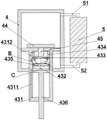
In one embodiment, the staging cylinder 43 further includes a third piston 433 and a blocker 434; the third piston 433 and the retainer ring 434 are both arranged in the grading cylinder body 431; the retainer 434 is connected to an end of the grading cylinder body 431 near the first piston 42; the third piston 433 is slidably connected in the retainer 434 and connected to an end of the push rod 45 away from the push plate 44.
Specifically, the outer wall of the retainer 434 abuts against the classification cylinder body 431; the inner wall of the baffle ring 434 abuts against the outer wall of the third piston 433; the third piston 433 is hermetically and slidably connected in the baffle ring 434, and the third piston 433 hermetically separates the rodless cavity into a first cavity and a second cavity; the first cavity, the second cavity and the rod cavity are sequentially arranged along the central axis direction of the cavity; the maximum stroke of the third piston 433 is to displace to the end of the retainer 434 away from the first piston 42.
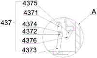
In one embodiment, the staging cylinder 43 further includes a fourth piston 435; the fourth piston 435 is slidably connected to the stepped cylinder body 431 between the third piston 433 and the second piston 432; a booster assembly 437 is disposed between the third piston 433 and the fourth piston 435.
In one embodiment, the boost assembly 437 includes multiple sets of crank assemblies; the crank assemblies surround the central axis of the cavity and are uniformly distributed.
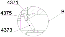
In one embodiment, the crank assembly comprises a first crank 4371 and a second crank 4373; one end of the first crank 4371 is hinged to the third piston 433, and the other end of the first crank 4371 is provided with an arc-shaped hole 4372; one end of the second crank 4373 is hinged to the fourth piston 435, and the other end of the second crank 4373 is slidably connected to the arc-shaped hole 4372 through a rotating pin 4374.
Specifically, the first crank 4371 and the second crank 4373 are both arranged in a direction away from the central axis of the cavity; a first rotating groove matched with the first crank 4371 is formed in one end, facing the fourth piston 435, of the third piston 433; the third opening of the first rotation groove faces the fourth piston 435; a first rotating shaft is connected in the first rotating groove; one end of the first crank 4371, which is close to the third piston 433, is provided with a first through hole; the first crank 4371 is rotatably connected with the first rotating shaft through the first through hole;
a second rotating groove matched with the second crank 4373 is formed in one end, facing the third piston 433, of the fourth piston 435; the fourth opening of the second rotary groove faces the third piston 433; a second rotating shaft is connected in the second rotating groove; a second through hole is formed in one end, close to the third piston 433, of the second crank 4373; the second crank 4373 is rotatably connected with the second rotating shaft through the second through hole;
the second crank 4373 is slidably connected in the arc-shaped hole 4372 through the rotation pin 4374, and the radius of curvature of the arc-shaped hole 4372 is far away from the central axis of the cavity;
initially, the crank assembly is in a maximum tension state, and at this time, the rotating pin 4374 is located at one end of the arc-shaped hole 4372 close to the third piston 433; the included angle between the first crank 4371 and the second crank 4373 is greater than or less than degree; as the third piston 433 is displaced in the direction of the fourth piston 435, the rotation pin 4374 slides in the arc-shaped hole 4372 toward the end of the arc-shaped hole 4372 away from the third piston 433, and at the same time, the included angle between the first crank 4371 and the second crank 4373 decreases;
when the rotation pin 4374 is displaced to the end of the arcuate hole 4372 remote from the third piston 433, the angular proximity between the first crank 4371 and the second crank 4373 is such that the crank assembly is in an extreme condition.
In one embodiment, an end of the retainer 434 away from the first piston 42 is hinged to a plurality of third cranks 4375 adapted to the crank assembly; one end of the third crank 4375 is hinged to the stop ring 434, and the other end of the third crank 4375 is provided with a sliding groove 4376 adapted to the rotation pin 4374.
Specifically, the third crank 4375 is disposed toward the central axis of the cavity and is rotationally connected to the baffle ring 434 through a torsion spring; meanwhile, a fifth opening of the sliding groove 4376 faces the rotation pin 4374; as the third piston 433 displaces toward the fourth piston 435, the compression between the first crank 4371 and the second crank 4373 causes the rotation pin 4374 to displace toward the classification cylinder body 431, and the rotation pin 4374 slides into the sliding groove 4376 and drives the third crank 4375 to rotate during the displacement of the third piston 433 toward the fourth piston 435;
when the rotation pin 4374 slides to the end of the arc hole 4372 far from the third piston 433, the crank assembly is at the limit, and the third crank 4375 is at the maximum rotation angle; the rotating pin 4374 is clamped in the sliding groove 4376, the central axis of the second crank 4373 is aligned with the central axis of the third crank 4375, and the central axis of the second crank 4373 is close to the central axis of the first crank 4371, at this time, the third crank 4375 and the second crank 4373 form a pressurizing mechanism, and at the same time, the first crank 4371 can further amplify the pressurizing effect on the pressurizing mechanism, so that the pressure applied to the piston 433 by the third piston can be further pressurized through the above structure and transmitted to the piston rod 436 through the second sub-cavity.
In one embodiment, the crank assemblies are preferably 4 sets.
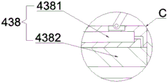
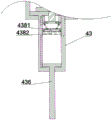
In one embodiment, an air bag module 438 is disposed between the fourth piston 435 and the second piston 432.
In one embodiment, the bladder assembly 438 comprises an inflator 4381 and a bladder 4382; an installation cavity is formed in the fourth piston 435; the inflation device 4381 is arranged in the installation cavity; the end of the fourth piston 435 facing the second piston 432 is connected with the air bag 4382; the air bag 4382 is communicated with the inflating device 4381.
Specifically, the inflating device 4381 comprises an air pump; one end of the air pump is communicated with one end of the air bag 4382 through an air outlet pipeline, and the other end of the air pump is communicated with the other end of the air bag 4382 through an air inlet pipeline; with the arrangement, the air pump, the air outlet pipeline, the air inlet pipeline and the air bag 4382 form a circulation loop; the air pump and the air bag 4382 belong to the prior art, and will not be described again.
In one embodiment, the first piston 42, the second piston 432, the third piston 433, the fourth piston 435, and the push plate 44 are parallel to each other.
Specifically, the fourth piston 435 is disposed in the second cavity and hermetically separates the second cavity to form a first sub-cavity and a second sub-cavity; the first cavity, the first sub-cavity, the second sub-cavity and the rod cavity are sequentially arranged along the central axis direction of the cavity; the boosting assembly 437 is arranged in the first cavity, and the air bag assembly 438 is arranged in the second cavity;
the second sub-chamber is communicated with the rod chamber through the first channel 4311; the oil tank 5 is communicated with the second sub-chamber through the second pipeline 52, the second channel 421 and the third channel 4312.
In one embodiment, the central axis of the push plate 44, the central axis of the push rod 45, the central axis of the third piston 433, and the central axis of the fourth piston 435 all coincide.
In one embodiment, the grading cylinder body 431 is provided with a fourth channel; the first cavity is communicated with the first sub-cavity through the fourth channel.
Specifically, a fifth control valve is arranged in the fourth channel; the fifth control valve is also externally connected with the pressure pump.
The using process is as follows:
starting the first control valve and the second control valve, feeding the hydraulic oil in the oil tank 5 into the first oil cavity through the first pipeline 51 under the action of the pressure pump, and allowing the hydraulic oil in the second oil cavity to flow into the oil tank 5 through the second pipeline 52; as the hydraulic oil in the first oil chamber increases and the hydraulic oil in the second oil chamber decreases, the first piston 42 drives the grading cylinder 43 and the cutting tool 7 to move downward at a high speed, so that a first cutting stroke is realized;
in the descending process, as the oil pressure in the first oil cavity increases, the push plate 44 pushes the third piston 433 to displace towards one end of the grading cylinder body 431 close to the piston rod 436, and at the same time, the fifth control valve is started, so that the hydraulic oil in the first sub-cavity flows into the first cavity through the fourth channel;
when the first piston 42 is displaced to the end of the hydraulic cylinder body 41 close to the piston rod 436, the first stroke is ended, and at this time, the rotation pin 4374 slides into the sliding groove 4376 during the displacement of the third piston 433 toward the fourth piston 435, so that the first crank 4371, the second crank 4373 and the third crank 4375 form a force increasing mechanism of the classification cylinder 43; the oil pressure in the first oil cavity is transmitted to the third piston 433 through the push plate 44, and the oil pressure of the third piston 433 is transmitted to the fourth piston 435 through the force-increasing structure, so that the hydraulic pressure is amplified; through the arrangement, the hydraulic cylinder 4 can output a large hydraulic pressure with small power and energy consumption;
starting the second control valve, the third control valve and the fourth control valve and closing the first control valve and the fifth control valve, wherein the hydraulic oil in the rod cavity is fed into the sub-cavity through the first channel 4311 under the action of the pressure pump, and meanwhile, the hydraulic oil in the oil tank 5 is also fed into the second sub-cavity through the second pipeline 52, the second channel 421 and the third channel 4312 under the action of the pressure pump, so that the second piston 432 drives the piston rod 436 to displace towards one end of the grading cylinder body 431 away from the first piston 42; the piston rod 436 drives the cutting tool 7 to move downwards at a high speed, so that a second cutting stroke is realized;
in the cutting process, the hydraulic oil in the rod cavity and the oil tank 5 is continuously supplemented into the second sub-cavity under the action of the pressure pump, so that the oil pressure in the second sub-cavity is increased, the hydraulic pressure output by the piston rod 436 is continuously improved, and the rapid cutting of the section is facilitated;
meanwhile, in the cutting process, the inflating device 4381 can be started according to actual conditions, the gas cylinder supplies gas into the gas bag 4382, and the volume of the gas bag 4382 is increased, so that the oil pressure in the second sub-cavity is increased, and the hydraulic pressure during cutting is amplified;
during return trip, the above processes are repeated in reverse.
The technical features of the embodiments described above may be arbitrarily combined, and for the sake of brevity, all possible combinations of the technical features in the embodiments described above are not described, but should be considered as being within the scope of the present specification as long as there is no contradiction between the combinations of the technical features.
The above-mentioned embodiments only express several embodiments of the present invention, and the description thereof is more specific and detailed, but not construed as limiting the scope of the invention. It should be noted that, for a person skilled in the art, several variations and modifications can be made without departing from the inventive concept, which falls within the scope of the present invention. Therefore, the protection scope of the present patent shall be subject to the appended claims.
Claims (10)
1. A profile cutting apparatus, comprising a base;
two ends of the top of the base are connected with mounting beams through upright posts;
the two sides of the bottom of the mounting beam are connected with mounting plates through hydraulic cylinders;
the bottom of the mounting plate is connected with a cutting tool;
the hydraulic cylinder comprises a hydraulic cylinder body, a first piston and a grading cylinder;
one end of the hydraulic cylinder body is connected with the mounting beam, and the other end of the hydraulic cylinder body is provided with a first opening;
the first piston is connected in the hydraulic cylinder body in a sliding mode;
the grading cylinder is arranged in the hydraulic cylinder body, one end of the grading cylinder is connected with the first piston, and the other end of the grading cylinder hermetically extends out of the hydraulic cylinder body through the first opening and is connected with the mounting plate.
2. The profile cutting apparatus according to claim 1, wherein the staging cylinder comprises a staging cylinder body, a second piston and a piston rod;
the second piston is connected in the grading cylinder body in a sliding mode;
one end of the piston rod is fixedly connected with one end, far away from the first piston, of the second piston, and the other end of the piston rod hermetically extends out of the grading cylinder body and is connected with the mounting plate.
3. The section bar cutting equipment according to claim 2, wherein a first oil port and a second oil port for introducing hydraulic oil are formed in the side wall of the hydraulic cylinder body;
the first oil port is positioned at one end of the hydraulic cylinder body close to the mounting beam;
the second oil port is located at one end, close to the mounting plate, of the hydraulic cylinder body.
4. The profile cutting apparatus according to claim 3, wherein the hydraulic cylinder circumscribes an oil tank;
a first pipeline is arranged at one end of the oil tank, and a second pipeline is arranged at the other end of the oil tank;
one end of the first pipeline is communicated with the oil tank, and the other end of the first pipeline is communicated with the hydraulic cylinder through the first oil port;
one end of the second pipeline is communicated with the oil tank, and the other end of the second pipeline is communicated with the hydraulic cylinder through the second oil port.
5. The profile cutting apparatus according to claim 3, wherein the second piston divides the stepped cylinder body into a rod chamber and a rodless chamber;
a first channel is formed in the side wall of the grading cylinder body;
the rod cavity is communicated with the rodless cavity through the first channel.
6. The profile cutting apparatus according to claim 5, wherein the first piston has a second passage opened on an outer circumference thereof;
a third channel is formed in the side wall of the grading cylinder body;
when the first piston moves to the maximum stroke position, one end of the second channel is butted with the second oil port, and the other end of the second channel is communicated with one end of the third channel;
the other end of the third channel is communicated with the rodless cavity.
7. The profile cutting apparatus according to claim 2, wherein the hydraulic cylinder further comprises a push plate and a push rod;
the push plate is arranged in the hydraulic cylinder body and is positioned on one side of the first piston, which is far away from the piston rod;
one end of the push rod is connected with the push plate, and the other end of the push rod penetrates through the first piston in a sealing mode and extends into the grading cylinder.
8. The profile cutting apparatus according to claim 7, wherein the diameter of the push plate is greater than the diameter of the second piston and less than the diameter of the first piston.
9. The profile cutting apparatus according to claim 7, wherein the staging cylinder further comprises a third piston and a stop ring;
the third piston and the baffle ring are both arranged in the grading cylinder body;
the baffle ring is connected to one end, close to the first piston, of the grading cylinder body;
the third piston is connected in the baffle ring in a sliding mode and is connected with one end, far away from the push plate, of the push rod.
10. The profile cutting apparatus according to claim 9, wherein the staging cylinder further comprises a fourth piston;
the fourth piston is slidably connected within the classification cylinder body and located between the third piston and the second piston;
and a boosting assembly is arranged between the third piston and the fourth piston.
Priority Applications (1)
| Application Number | Priority Date | Filing Date | Title |
|---|---|---|---|
| CN202110871426.4A CN113681082A (en) | 2021-07-30 | 2021-07-30 | Section bar cutting equipment |
Applications Claiming Priority (1)
| Application Number | Priority Date | Filing Date | Title |
|---|---|---|---|
| CN202110871426.4A CN113681082A (en) | 2021-07-30 | 2021-07-30 | Section bar cutting equipment |
Publications (1)
| Publication Number | Publication Date |
|---|---|
| CN113681082A true CN113681082A (en) | 2021-11-23 |
Family
ID=78578396
Family Applications (1)
| Application Number | Title | Priority Date | Filing Date |
|---|---|---|---|
| CN202110871426.4A Withdrawn CN113681082A (en) | 2021-07-30 | 2021-07-30 | Section bar cutting equipment |
Country Status (1)
| Country | Link |
|---|---|
| CN (1) | CN113681082A (en) |
Citations (9)
| Publication number | Priority date | Publication date | Assignee | Title |
|---|---|---|---|---|
| US4257163A (en) * | 1979-04-27 | 1981-03-24 | Wolfgang Bauer | Automotive service tool |
| CN101787989A (en) * | 2009-01-23 | 2010-07-28 | 徐洪德 | Multi-level piston two-way hydraulic cylinder |
| CN102744454A (en) * | 2012-07-27 | 2012-10-24 | 苏州大学 | Pneumatic two-stage toggle rod reinforcement-hydraulic synchronous compound transmission plate shearing machine driving device |
| CN205823787U (en) * | 2016-06-21 | 2016-12-21 | 徐州重型机械有限公司 | Twin-stage compound hydralic oil cylinder |
| CN110345127A (en) * | 2019-07-12 | 2019-10-18 | 南通翔骜液压润滑设备有限公司 | Multistage hydraulic cylinder |
| CN110370705A (en) * | 2019-07-22 | 2019-10-25 | 中南大学 | Segmented multiple-pass hydraulic press |
| CN211991158U (en) * | 2020-04-15 | 2020-11-24 | 郑州科技学院 | Intelligent cutting robot |
| CN112196863A (en) * | 2019-07-08 | 2021-01-08 | 无锡市华通液压气动制造有限公司 | Novel two-action three-stage cylinder |
| CN213052955U (en) * | 2020-07-22 | 2021-04-27 | 香河胜兴实业有限公司 | Stable hydraulic plate shearing machine |
-
2021
- 2021-07-30 CN CN202110871426.4A patent/CN113681082A/en not_active Withdrawn
Patent Citations (9)
| Publication number | Priority date | Publication date | Assignee | Title |
|---|---|---|---|---|
| US4257163A (en) * | 1979-04-27 | 1981-03-24 | Wolfgang Bauer | Automotive service tool |
| CN101787989A (en) * | 2009-01-23 | 2010-07-28 | 徐洪德 | Multi-level piston two-way hydraulic cylinder |
| CN102744454A (en) * | 2012-07-27 | 2012-10-24 | 苏州大学 | Pneumatic two-stage toggle rod reinforcement-hydraulic synchronous compound transmission plate shearing machine driving device |
| CN205823787U (en) * | 2016-06-21 | 2016-12-21 | 徐州重型机械有限公司 | Twin-stage compound hydralic oil cylinder |
| CN112196863A (en) * | 2019-07-08 | 2021-01-08 | 无锡市华通液压气动制造有限公司 | Novel two-action three-stage cylinder |
| CN110345127A (en) * | 2019-07-12 | 2019-10-18 | 南通翔骜液压润滑设备有限公司 | Multistage hydraulic cylinder |
| CN110370705A (en) * | 2019-07-22 | 2019-10-25 | 中南大学 | Segmented multiple-pass hydraulic press |
| CN211991158U (en) * | 2020-04-15 | 2020-11-24 | 郑州科技学院 | Intelligent cutting robot |
| CN213052955U (en) * | 2020-07-22 | 2021-04-27 | 香河胜兴实业有限公司 | Stable hydraulic plate shearing machine |
Similar Documents
| Publication | Publication Date | Title |
|---|---|---|
| US6895749B2 (en) | Double-acting pressure intensifying cylinder and method for intensifying pressure in the cylinder | |
| EP2985462B1 (en) | Fold-back coaxial gas booster pump and gas pressure creating method | |
| CN103148046B (en) | A kind of direct-drive supercharged formula of AC servo three layers of piston electrohydraulic cylinder and boosting method | |
| CN213451090U (en) | Multi-stage linkage telescopic gas-liquid driving device | |
| CN101725580B (en) | Hydraulic pressure cylinder | |
| US6270323B1 (en) | Hydraulic power conversion device | |
| CN113681082A (en) | Section bar cutting equipment | |
| CN100360813C (en) | Integrated electrohydraulic actuator for fast action and adjustment | |
| CN109611308B (en) | High-pressure variable plunger pump | |
| KR100898028B1 (en) | Variable hydraulic pump | |
| US20210172428A1 (en) | Compressor and method for conveying and compressing a fluid for conveyance into a target system | |
| CN119914725A (en) | A kind of impact piece and pressure reducing valve having the same | |
| CN110345037B (en) | Pneumatic oil pressure pump | |
| CN210660475U (en) | Wind energy supercharging device | |
| CN207830238U (en) | A kind of split type large-scale hydraulic ram | |
| EP1998045A1 (en) | Displacement machine with coaxial valves | |
| CN103277276A (en) | Ultrahigh pressure multistage radial plunger pump | |
| CN110345112B (en) | High-speed and oil-gas isolated gas-liquid booster cylinder | |
| CN117428721A (en) | Electric hydraulic tool | |
| CN212646604U (en) | Novel chromatographic column packing system with ultra-long pressure maintaining time | |
| CN112459997B (en) | Low-permeability coal bed gas compression device for permeability increase | |
| CN107035646A (en) | A kind of super-pressure Portable inflator pump | |
| CN112901474B (en) | Piston pump and clamping device with same | |
| US6079209A (en) | Hydraulic power conversion device | |
| CN215634640U (en) | Filling device |
Legal Events
| Date | Code | Title | Description |
|---|---|---|---|
| PB01 | Publication | ||
| PB01 | Publication | ||
| SE01 | Entry into force of request for substantive examination | ||
| SE01 | Entry into force of request for substantive examination | ||
| WW01 | Invention patent application withdrawn after publication | ||
| WW01 | Invention patent application withdrawn after publication |
Application publication date: 20211123 |