CN113671663B - Optical lens and electronic device - Google Patents
Optical lens and electronic device Download PDFInfo
- Publication number
- CN113671663B CN113671663B CN202010401156.6A CN202010401156A CN113671663B CN 113671663 B CN113671663 B CN 113671663B CN 202010401156 A CN202010401156 A CN 202010401156A CN 113671663 B CN113671663 B CN 113671663B
- Authority
- CN
- China
- Prior art keywords
- lens
- optical
- optical lens
- focal length
- equal
- Prior art date
- Legal status (The legal status is an assumption and is not a legal conclusion. Google has not performed a legal analysis and makes no representation as to the accuracy of the status listed.)
- Active
Links
- 230000003287 optical effect Effects 0.000 title claims abstract description 317
- 238000003384 imaging method Methods 0.000 claims description 55
- 210000001747 pupil Anatomy 0.000 claims description 10
- 230000004075 alteration Effects 0.000 description 18
- 230000001681 protective effect Effects 0.000 description 12
- 238000005286 illumination Methods 0.000 description 11
- 230000009286 beneficial effect Effects 0.000 description 9
- 238000010586 diagram Methods 0.000 description 6
- 230000004907 flux Effects 0.000 description 6
- 230000009467 reduction Effects 0.000 description 6
- 230000005540 biological transmission Effects 0.000 description 5
- 230000000694 effects Effects 0.000 description 4
- 239000011521 glass Substances 0.000 description 4
- 230000005499 meniscus Effects 0.000 description 4
- 239000000463 material Substances 0.000 description 3
- 230000008859 change Effects 0.000 description 2
- 238000012937 correction Methods 0.000 description 2
- 238000013461 design Methods 0.000 description 2
- 238000005516 engineering process Methods 0.000 description 2
- 230000014509 gene expression Effects 0.000 description 2
- 230000002093 peripheral effect Effects 0.000 description 2
- 230000004304 visual acuity Effects 0.000 description 2
- 230000003044 adaptive effect Effects 0.000 description 1
- 230000000295 complement effect Effects 0.000 description 1
- 238000011161 development Methods 0.000 description 1
- 230000002349 favourable effect Effects 0.000 description 1
- 230000006872 improvement Effects 0.000 description 1
- 230000003993 interaction Effects 0.000 description 1
- 238000004519 manufacturing process Methods 0.000 description 1
- 229910044991 metal oxide Inorganic materials 0.000 description 1
- 150000004706 metal oxides Chemical class 0.000 description 1
- 238000012545 processing Methods 0.000 description 1
- 239000004065 semiconductor Substances 0.000 description 1
- 238000012546 transfer Methods 0.000 description 1
- 230000007704 transition Effects 0.000 description 1
- XLYOFNOQVPJJNP-UHFFFAOYSA-N water Substances O XLYOFNOQVPJJNP-UHFFFAOYSA-N 0.000 description 1
Images


Classifications
-
- G—PHYSICS
- G02—OPTICS
- G02B—OPTICAL ELEMENTS, SYSTEMS OR APPARATUS
- G02B13/00—Optical objectives specially designed for the purposes specified below
- G02B13/001—Miniaturised objectives for electronic devices, e.g. portable telephones, webcams, PDAs, small digital cameras
- G02B13/0015—Miniaturised objectives for electronic devices, e.g. portable telephones, webcams, PDAs, small digital cameras characterised by the lens design
- G02B13/002—Miniaturised objectives for electronic devices, e.g. portable telephones, webcams, PDAs, small digital cameras characterised by the lens design having at least one aspherical surface
- G02B13/004—Miniaturised objectives for electronic devices, e.g. portable telephones, webcams, PDAs, small digital cameras characterised by the lens design having at least one aspherical surface having four lenses
-
- G—PHYSICS
- G02—OPTICS
- G02B—OPTICAL ELEMENTS, SYSTEMS OR APPARATUS
- G02B13/00—Optical objectives specially designed for the purposes specified below
- G02B13/18—Optical objectives specially designed for the purposes specified below with lenses having one or more non-spherical faces, e.g. for reducing geometrical aberration
-
- H—ELECTRICITY
- H04—ELECTRIC COMMUNICATION TECHNIQUE
- H04N—PICTORIAL COMMUNICATION, e.g. TELEVISION
- H04N9/00—Details of colour television systems
- H04N9/12—Picture reproducers
- H04N9/31—Projection devices for colour picture display, e.g. using electronic spatial light modulators [ESLM]
- H04N9/3141—Constructional details thereof
Landscapes
- Physics & Mathematics (AREA)
- General Physics & Mathematics (AREA)
- Optics & Photonics (AREA)
- Engineering & Computer Science (AREA)
- Multimedia (AREA)
- Signal Processing (AREA)
- Lenses (AREA)
Abstract
The application discloses an optical lens and an electronic device including the same. The optical lens sequentially comprises from a first side to a second side along an optical axis: a first lens having a positive refractive power, a first side surface of which is convex and a second side surface of which is concave; a second lens with negative focal power, wherein the first side surface of the second lens is a concave surface, and the second side surface of the second lens is a convex surface; a third lens with positive focal power, wherein the first side surface of the third lens is a convex surface; and a fourth lens having a positive refractive power, the first side of which is convex and the second side of which is concave.
Description
Technical Field
The present disclosure relates to the field of optical elements, and more particularly, to an optical lens and an electronic device.
Background
With the development of automobile lighting technology, the headlights of automobiles are developed from the direction of only having the conventional lighting function and considering both the Adaptive Driving Beam (ADB) and the ground projection function. For example, a car may have ADB functionality while driving at night; at night, the automobile can also project different marks in front of the automobile for the purpose of human-vehicle interaction.
In order to achieve both ADB and ground projection, a Digital Light Processing (DLP) headlamp based on an intelligent controllable LED chip is generally used. DLP headlight is the mainstream of future intelligent headlight. Compared to the optical lenses in lighting systems, which usually do not take care of chromatic aberrations, the optical lenses in DLP headlamps take care of both lighting and projection. Therefore, the optical lens in the DLP headlamp needs to have high light efficiency and good projection picture. Furthermore, the working environment of a DLP headlamp is worse than that of an optical lens in a typical projection system, for example, the ambient temperature is extreme or fluctuates greatly compared to the room temperature.
Therefore, the market expects an optical lens with high light efficiency and at least one of the optical performances of small chromatic aberration, good image resolution, large projection range or good temperature performance.
Disclosure of Invention
An aspect of the present application provides an optical lens, which includes, in order from a first side to a second side along an optical axis: the first lens with positive focal power has a convex first side surface and a concave second side surface; the first side surface of the second lens is a concave surface, and the second side surface of the second lens is a convex surface; a third lens with positive focal power, wherein the first side surface of the third lens is a convex surface; and a fourth lens having a positive refractive power, the first side of which is convex and the second side of which is concave.
In one embodiment, the second side of the third lens is concave.
In one embodiment, the second side of the third lens is convex.
In one embodiment, the total optical length TTL of the optical lens and the total effective focal length F of the optical lens may satisfy: TTL/F is less than or equal to 4.5.
In one embodiment, the total effective focal length F of the optical lens and the entrance pupil diameter EPDI of the optical lens may satisfy: F/EPDI is less than or equal to 1.2.
In one embodiment, the effective focal length F1 of the first lens and the effective focal length F2 of the second lens may satisfy: the ratio of F1 to F2 is less than or equal to 4.
In one embodiment, the effective focal length F2 of the second lens and the effective focal length F3 of the third lens may satisfy: the ratio of F3 to F2 is less than or equal to 4.
In one embodiment, the effective focal length F1 of the first lens and the effective focal length F3 of the third lens may satisfy: F1/F3 is less than or equal to 4.5.
In one embodiment, the effective focal length F2 of the second lens and the total effective focal length F of the optical lens may satisfy: and the | F2/F | is more than or equal to 1.8.
In one embodiment, the effective focal length F4 of the fourth lens and the total effective focal length F of the optical lens may satisfy: F4/F is less than or equal to 5.
In one embodiment, the effective focal length F3 of the third lens and the effective focal length F4 of the fourth lens may satisfy: F3/F4 is less than or equal to 5.
In one embodiment, the central radius of curvature R3 of the first side of the second lens, the central radius of curvature R4 of the second side of the second lens, and the central thickness d3 of the second lens on the optical axis may satisfy: R3/(R4+ d3) is less than or equal to 2.
In one embodiment, the central radius of curvature R8 of the first side of the fourth lens, the central radius of curvature R9 of the second side of the fourth lens, and the central thickness d8 of the fourth lens on the optical axis may satisfy: R8/(R9+ d8) is less than or equal to 1.5.
In one embodiment, the back focal length BFL of the optical lens and the total effective focal length F of the optical lens may satisfy: BFL/F is less than or equal to 0.5.
In one embodiment, the effective focal length F1 of the first lens and the distance d2 on the optical axis from the second side of the first lens to the first side of the second lens can satisfy: f1/d2 is more than or equal to 3.
In one embodiment, the maximum clear aperture Φ 1 of the first lens, the maximum clear aperture Φ 2 of the second lens, the maximum clear aperture Φ 3 of the third lens, and the maximum clear aperture Φ 4 of the fourth lens may satisfy: phi 1 is more than or equal to phi 2 and more than or equal to phi 3 and more than or equal to phi 4.
In one embodiment, in each field of view of the optical lens, the angle between each ray in the exit pupil of the first side of the first lens and the chief ray is the exit angle of the first lens, and the value of the exit angle of the first lens is not more than 1 °.
Another aspect of the present application provides such an optical lens. The optical lens sequentially comprises from a first side to a second side along an optical axis: a first lens having a positive optical power; a second lens having a negative optical power; a third lens having a positive optical power; and a fourth lens having a positive optical power; wherein, the total effective focal length F of the optical lens and the entrance pupil diameter EPDI of the optical lens can satisfy: F/EPDI is less than or equal to 1.2.
In one embodiment, the first side of the first lens is convex and the second side of the first lens is concave.
In one embodiment, the first side of the second lens is concave and the second side of the second lens is convex.
In one embodiment, the first side of the fourth lens is convex and the second side of the fourth lens is concave.
In one embodiment, the first side of the third lens is convex. Optionally, the second side of the third lens is concave. Optionally, the second side of the third lens is convex.
In one embodiment, the total optical length TTL of the optical lens and the total effective focal length F of the optical lens may satisfy: TTL/F is less than or equal to 4.5.
In one embodiment, the effective focal length F1 of the first lens and the effective focal length F2 of the second lens may satisfy: the ratio of F1 to F2 is less than or equal to 4.
In one embodiment, the effective focal length F2 of the second lens and the effective focal length F3 of the third lens may satisfy: the ratio of F3 to F2 is less than or equal to 4.
In one embodiment, the effective focal length F1 of the first lens and the effective focal length F3 of the third lens may satisfy: F1/F3 is less than or equal to 4.5.
In one embodiment, the effective focal length F2 of the second lens and the total effective focal length F of the optical lens may satisfy: and the | F2/F | is more than or equal to 1.8.
In one embodiment, the effective focal length F4 of the fourth lens and the total effective focal length F of the optical lens may satisfy: F4/F is less than or equal to 5.
In one embodiment, the effective focal length F3 of the third lens and the effective focal length F4 of the fourth lens may satisfy: F3/F4 is less than or equal to 5.
In one embodiment, the central radius of curvature R3 of the first side of the second lens, the central radius of curvature R4 of the second side of the second lens, and the central thickness d3 of the second lens on the optical axis may satisfy: R3/(R4+ d3) is less than or equal to 2.
In one embodiment, the central radius of curvature R8 of the first side of the fourth lens, the central radius of curvature R9 of the second side of the fourth lens, and the central thickness d8 of the fourth lens on the optical axis may satisfy: R8/(R9+ d8) is less than or equal to 1.5.
In one embodiment, the back focal length BFL of the optical lens and the total effective focal length F of the optical lens may satisfy: BFL/F is less than or equal to 0.5.
In one embodiment, the effective focal length F1 of the first lens and the distance d2 on the optical axis from the second side of the first lens to the first side of the second lens can satisfy: f1/d2 is more than or equal to 3.
In one embodiment, the maximum clear aperture Φ 1 of the first lens, the maximum clear aperture Φ 2 of the second lens, the maximum clear aperture Φ 3 of the third lens, and the maximum clear aperture Φ 4 of the fourth lens may satisfy: phi 1 is more than or equal to phi 2 and more than or equal to phi 3 and more than or equal to phi 4.
In one embodiment, in each field of view of the optical lens, the angle between each ray in the exit pupil of the first side of the first lens and the chief ray is the exit angle of the first lens, and the value of the exit angle of the first lens is not more than 1 °.
Another aspect of the present application provides an electronic device including an optical lens provided according to the present application and a light emitting source for converting an electrical signal into an optical signal, the optical signal forming an image via the optical lens.
Another aspect of the present application provides an electronic device, which includes the optical lens and an imaging element for converting an optical image formed by the optical lens into an electrical signal.
The application provides an optical lens has adopted four lens, and it has following at least one beneficial effect:
1) the requirements of large relative aperture and high light flux can be realized by only four lenses through the shape and focal power of the lenses which are reasonably arranged.
2) The optical lens has high luminous efficiency of more than 30%.
3) The resolution definition of the optical lens is consistent in the field range, and the optical lens has high resolution quality.
4) The optical lens realizes the effect of small color difference of the projection surface, and then the projection effect is improved.
5) And the optical lens can ensure the light receiving range and improve the light transmission quantity.
6) The surface of the optical lens facing the first side is a convex surface, so that better appearance performance can be provided in a limited space.
7) The temperature performance is good, the imaging effect change is small at high and low temperatures, and the image quality is stable. It can ensure a good Modulation Transfer Function (MTF) in the temperature range of-20 ℃ to 105 ℃ to work under most driving conditions of the vehicle.
Drawings
Other features, objects, and advantages of the present application will become more apparent from the following detailed description of non-limiting embodiments when taken in conjunction with the accompanying drawings. In the drawings:
fig. 1 is a schematic view showing a structure of an optical lens according to embodiment 1 of the present application;
fig. 2 is a schematic structural view showing an optical lens according to embodiment 2 of the present application;
fig. 3 is a schematic structural view showing an optical lens according to embodiment 3 of the present application;
fig. 4 is a schematic structural view showing an optical lens according to embodiment 4 of the present application;
fig. 5 is a schematic structural view showing an optical lens according to embodiment 5 of the present application; and
fig. 6 is a schematic view showing a structure of an optical lens according to embodiment 6 of the present application.
Detailed Description
For a better understanding of the present application, various aspects of the present application will be described in more detail with reference to the accompanying drawings. It should be understood that the detailed description is merely illustrative of exemplary embodiments of the present application and does not limit the scope of the present application in any way. Like reference numerals refer to like elements throughout the specification. The expression "and/or" includes any and all combinations of one or more of the associated listed items.
It should be noted that in this specification the expressions first, second, third etc. are only used to distinguish one feature from another, and do not represent any limitation on the features. Thus, the first lens discussed below may also be referred to as the second lens or the third lens without departing from the teachings of the present application.
In the drawings, the thickness, size, and shape of the lens have been slightly exaggerated for convenience of explanation. In particular, the shapes of the spherical or aspherical surfaces shown in the drawings are shown by way of example. That is, the shape of the spherical surface or the aspherical surface is not limited to the shape of the spherical surface or the aspherical surface shown in the drawings. The figures are purely diagrammatic and not drawn to scale.
Herein, the paraxial region refers to a region near the optical axis. If the lens surface is convex and the convex position is not defined, it means that the lens surface is convex at least in the paraxial region; if the lens surface is concave and the concave position is not defined, it means that the lens surface is concave at least in the paraxial region. The surface of each lens closest to the first side is referred to as the first side of the lens and the surface of each lens closest to the second side is referred to as the second side of the lens.
It will be further understood that the terms "comprises," "comprising," "has," "having," "includes" and/or "including," when used in this specification, specify the presence of stated features, elements, and/or components, but do not preclude the presence or addition of one or more other features, elements, components, and/or groups thereof. Moreover, when a statement such as "at least one of" appears after the list of listed features, that the entirety of the listed features is modified rather than modifying individual elements in the list. Furthermore, when describing embodiments of the present application, the use of "may" mean "one or more embodiments of the present application. Also, the term "exemplary" is intended to refer to an example or illustration.
Unless otherwise defined, all terms (including technical and scientific terms) used herein have the same meaning as commonly understood by one of ordinary skill in the art to which this application belongs. It will be further understood that terms, such as those defined in commonly used dictionaries, should be interpreted as having a meaning that is consistent with their meaning in the context of the relevant art and will not be interpreted in an idealized or overly formal sense unless expressly so defined herein.
It should be noted that the embodiments and features of the embodiments in the present application may be combined with each other without conflict. The present application will be described in detail below with reference to the accompanying drawings in conjunction with embodiments.
The features, principles and other aspects of the present application are described in detail below.
In an exemplary embodiment, the optical lens includes, for example, four lenses having optical powers, i.e., a first lens, a second lens, a third lens, and a fourth lens. The four lenses are arranged in sequence from the first side to the second side along the optical axis.
In an exemplary embodiment, the optical lens provided by the present application can be used as, for example, a vehicle-mounted lens, and the first side of the optical lens is an object side and the second side is an image side. Light from the object can be imaged on the image side.
In an exemplary embodiment, the optical lens provided herein can be used, for example, as a projection lens, the second side of the optical lens being an image source side and the first side being an image forming side. Light from the image source side can be imaged on the image side.
In an exemplary embodiment, the first lens may have a positive optical power. The first lens may have a convex-concave type. The first lens has a meniscus shape with a convex surface facing the first side, which helps to diverge the light rays and thus increase the range of the image formed on the first side. The positive focal power can also have a long-focus characteristic, which is beneficial to increasing the clear aperture. In practical applications, for example, considering that the environment for installing and using the vehicle-mounted lens outdoors is in bad weather such as rain and snow, the shape is beneficial to the sliding of water drops so as to reduce the influence on imaging.
Illustratively, the first lens may be an aspheric lens to further improve the resolution quality. Illustratively, the material of the first lens may be a low refractive index material to facilitate reducing chromatic aberration of the optical lens.
In an exemplary embodiment, the second lens may have a negative power. The second lens may have a meniscus type. The second lens with negative focal power has a meniscus shape with a convex surface facing the second side, which helps to collect light, and helps to increase the aberration correction capability, reduce chromatic aberration, and improve the resolution capability of the optical lens. For example, the first side surface and the second side surface of the second lens may have shapes similar to concentric circles, so that there is an optical path difference between the peripheral light rays and the central light rays, and thus the central light rays may be dispersed and the projection angle may be increased.
In an exemplary embodiment, the third lens may have a positive optical power. The third lens may have a convex-concave type or a double-convex type. Illustratively, the effective focal length F3 of the third lens and the total effective focal length F of the optical lens satisfy F3/F ≦ 15. By controlling the focal length value of the third lens, the light rays emitted by the fourth lens can be better controlled, so that the large light flux of the optical lens is ensured, and the relative illumination is increased. Specifically, F3 and F may satisfy: F3/F is less than or equal to 6.
In an exemplary embodiment, the fourth lens may have a positive optical power. The fourth lens may have a convex-concave type. The fourth lens has a meniscus shape with the convex surface facing the first side, and can collect more light from the second side.
Illustratively, the refractive index Nd4 of the fourth lens may satisfy: nd4 is more than or equal to 1.65. The fourth lens with large refractive index can further improve the light collecting capability of the fourth lens. More specifically, Nd4 further satisfies 1.75. ltoreq. Nd 4. ltoreq.1.85. Illustratively, the fourth lens has a short-focus design, which is beneficial to improving the resolution of the optical lens. Illustratively, the first side surface and the second side surface of the fourth lens may have an approximately concentric circular shape, may receive more light rays from the second side, and may be advantageous to improve luminous flux.
In an exemplary embodiment, each of the first lens, the second lens, the third lens and the fourth lens may have an aspherical mirror surface. The aspheric lens is characterized in that: the curvature varies continuously from the center to the periphery of the lens. Unlike a spherical lens having a constant curvature from the center to the periphery of the lens, an aspherical lens has better curvature radius characteristics, and has advantages of improving distortion aberration and improving astigmatic aberration. After the aspheric lens is adopted, the aberration generated in imaging can be eliminated as much as possible, so that the imaging quality of the lens is improved. The aspheric lens helps to correct system aberration and improve resolving power. Specifically, at least one lens of the first lens, the second lens, the third lens and the fourth lens is an aspheric lens, which is beneficial to improving the resolution quality of the optical system. For example, the first side surface of the first lens to the second side surface of the fourth lens may be aspheric, and the profile x of each aspheric lens may be defined using, but not limited to, the following aspheric formula:

wherein x is the rise of the distance from the aspheric surface vertex to the aspheric surface vertex when the aspheric surface is at the position with the height of h along the optical axis direction; c is the paraxial curvature of the aspheric surface, c being 1/R (i.e., paraxial curvature c is the inverse of radius of curvature R in table 1 above); k is a conic coefficient; ai is the correction coefficient of the i-th order of the aspheric surface.
In an exemplary embodiment, an optical lens according to the present application may satisfy TTL/F ≦ 4.5, where TTL is the total optical length of the optical lens and F is the total effective focal length of the optical lens. By controlling the ratio of the total optical length to the total effective focal length within this range, miniaturization of the optical lens is facilitated. Exemplarily, when the optical lens of the present application is used as, for example, an in-vehicle lens, the optical lens has an imaging surface located at the second side, and an on-axis distance from the first side surface of the first lens to the imaging surface of the optical lens is the total optical length TTL. Exemplarily, when the optical lens of the present application is used as, for example, a projection lens, the optical lens has a light emitting source surface located at the second side, and an on-axis distance from the first side surface of the first lens to the light emitting source surface of the optical lens is the total optical length TTL. More specifically, TTL and F further satisfy: TTL/F is less than or equal to 4.
In an exemplary embodiment, an optical lens according to the present application may satisfy F/EPDI ≦ 1.2, where F is the total effective focal length of the optical lens and EPDI is the entrance pupil diameter of the optical lens. The requirements that F/EPDI is less than or equal to 1.2 and the F-number Fno of the optical lens is small are met, so that the luminous flux of the optical lens is favorably improved, and the purpose of high luminous efficiency is achieved. More specifically, F and EPDI further may satisfy: F/EPDI is less than or equal to 1.
In an exemplary embodiment, an optical lens according to the present application may satisfy | F1/F2| ≦ 4, where F1 is an effective focal length of the first lens and F2 is an effective focal length of the second lens. The requirement that | F1/F2| is less than or equal to 4 is met, the focal powers of the first lens and the second lens are reasonably matched, and the aberration can be corrected while the light transmission quantity is ensured. More specifically, F1 and F2 further satisfy: the ratio of F1/F2 is less than or equal to 2.5.
In an exemplary embodiment, an optical lens according to the present application may satisfy | F3/F2| ≦ 4, where F2 is an effective focal length of the second lens and F3 is an effective focal length of the third lens. By controlling the absolute value of the ratio of the effective focal length of the third lens to the effective focal length of the second lens to be in the range, the optical power of the second lens and the optical power of the third lens are matched reasonably, and the aberration can be corrected while the light transmission quantity is ensured. More specifically, F2 and F3 further satisfy: the ratio of F3 to F2 is less than or equal to 2.5.
In an exemplary embodiment, an optical lens according to the present application may satisfy F1/F3 ≦ 4.5, where F1 is an effective focal length of the first lens and F3 is an effective focal length of the third lens. The first lens and the third lens are two adjacent positive lenses, and the range of the value of F1/F3 is controlled, so that the effective focal lengths of the first lens and the third lens are close to each other, smooth transition of light rays is facilitated, and the improvement of resolution quality is facilitated. More specifically. F1 and F3 further satisfy: F1/F3 is more than or equal to 0.4 and less than or equal to 3.5.
In an exemplary embodiment, an optical lens according to the present application may satisfy | F2/F | ≧ 1.8, where F2 is the effective focal length of the second lens and F is the total effective focal length of the optical lens. By satisfying | F2/F | ≧ 1.8, the focal length of the second lens can be reasonably set, which is beneficial to realizing thermal compensation. More specifically, F2 and F further satisfy: and | F2/F | ≧ 2.
In an exemplary embodiment, an optical lens according to the present application may satisfy F4/F ≦ 5, where F4 is an effective focal length of the fourth lens, and F is a total effective focal length of the optical lens. By satisfying F4/F is less than or equal to 5, the fourth lens can be set to have a short focal length, which is beneficial to light collection and further ensures the light transmission amount. More specifically, F4 and F further satisfy: F4/F is less than or equal to 4.5.
In an exemplary embodiment, an optical lens according to the present application may satisfy F3/F4 ≦ 5, where F3 is an effective focal length of the third lens and F4 is an effective focal length of the fourth lens. The optical lens meets the condition that F3/F4 is less than or equal to 5, the reasonable collocation of focal power is facilitated, and the third lens can better control the light rays emitted by the fourth lens so as to ensure large light flux and increase relative illumination. More specifically, F3 and F4 further satisfy: F3/F4 is less than or equal to 3.5.
In an exemplary embodiment, an optical lens according to the present application may satisfy R3/(R4+ d3) ≦ 2, where R3 is a central radius of curvature of the first side of the second lens, R4 is a central radius of curvature of the second side of the second lens, and d3 is a central thickness of the second lens on the optical axis. Satisfy R3/(R4+ d3) is less than or equal to 2, make the second lens have special lens shape, make peripheral light and central light have the optical path difference then, can disperse central light, and increase the projection angle. More specifically, R3, R4, and d3 may further satisfy: R3/(R4+ d3) is less than or equal to 1.8.
In an exemplary embodiment, an optical lens according to the present application may satisfy R8/(R9+ d8) ≦ 1.5, where R8 is a central radius of curvature of the first side of the fourth lens, R9 is a central radius of curvature of the second side of the fourth lens, and d8 is a central thickness of the fourth lens on the optical axis. The requirement of R8/(R9+ d8) is less than or equal to 1.5, so that the fourth lens has a special lens shape, and further more light rays on the second side can be received by the fourth lens, and the luminous flux is favorably improved. More specifically, R8, R9, and d8 may further satisfy: R8/(R9+ d8) is less than or equal to 1.2.
In an exemplary embodiment, an optical lens according to the present application may satisfy BFL/F ≦ 0.5, where BFL is a back focal length of the optical lens and F is a total effective focal length of the optical lens. By controlling the ratio of the back focal length to the total effective focal length within this range, a short back focal design can be achieved, which is further beneficial to improving the resolution quality. Illustratively, when the optical lens of the present application is used as, for example, an in-vehicle lens, the optical lens has an imaging surface located on the second side, and an on-axis distance from the second side surface of the fourth lens to the imaging surface of the optical lens is a back focal length BFL. Illustratively, when the optical lens of the present application is used as, for example, a projection lens, the optical lens has the light emission source surface on the second side, and the on-axis distance from the second side surface of the fourth lens to the light emission source surface of the optical lens is the back focal length BFL. More specifically, BFL and F further may satisfy: BFL/F is less than or equal to 0.35.
In an exemplary embodiment, an optical lens according to the present application may satisfy F1/d2 ≧ 3, where F1 is an effective focal length of the first lens, and d2 is a distance on an optical axis from the second side surface of the first lens to the first side surface of the second lens. The condition that F1/d2 is more than or equal to 3 is met, the emergent angle of marginal rays at the first lens is small, and clear images are formed at far positions. More specifically, F1 and d2 further satisfy: f1/d2 is more than or equal to 3.7.
In an exemplary embodiment, an optical lens according to the present application may satisfy φ 1 ≧ φ 2 ≧ φ 3 ≧ φ 4, where φ 1 is the maximum clear aperture of the first lens, φ 2 is the maximum clear aperture of the second lens, φ 3 is the maximum clear aperture of the third lens, and φ 4 is the maximum clear aperture of the fourth lens. By controlling the maximum light-passing apertures of the first lens to the fourth lens, the relative illumination of the optical lens is favorably ensured to be not less than 70%. Further, the relative illumination of the optical lens is not less than 80%.
In an exemplary embodiment, in each field of view of an optical lens according to the present application, the angle of each ray in the exit pupil of the first side of the first lens with respect to the chief ray is the exit angle of the first lens, the exit angle of the first lens having a value of not more than 1 °. By making the value of the exit angle of the first lens not more than 1 °, it is possible to ensure that a clear image is formed at a sufficiently far distance, for example, not less than 6 m. Further, a clear image can be formed at not less than 7 m.
In an exemplary embodiment, a stop for limiting the light beam may be disposed between the second lens and the third lens to further improve the imaging quality of the optical lens. The diaphragm is favorable for improving the projection effect. In the embodiment of the present application, the stop may be provided in the vicinity of the first side surface of the third lens, or in the vicinity of the second side surface of the second lens. It should be noted, however, that the positions of the diaphragms disclosed herein are merely examples and not limitations; in alternative embodiments, the diaphragm may be disposed at other positions according to actual needs.
In an exemplary embodiment, when the optical lens of the present application is used as an imaging lens, the optical lens of the present application may further include a filter disposed between the fourth lens and the imaging surface to filter light rays having different wavelengths, as needed.
According to the optical lens of the embodiment of the application, through reasonable setting of the shapes and the focal powers of the lenses, under the condition that only four lenses are used, at least one beneficial effect that the optical lens has high luminous efficiency, large light transmission quantity, small chromatic aberration, good resolving power, large projection range, good temperature performance, high relative illumination and the like is achieved. Meanwhile, the optical lens also has the characteristic of small lens volume, and meets the requirement of low cost.
In an exemplary embodiment, the first to fourth lenses in the optical lens may each be made of glass. The optical lens made of glass can inhibit the deviation of the back focus of the optical lens along with the temperature change so as to improve the stability of the system. Meanwhile, the glass material is adopted, so that the problem that the normal use of the lens is influenced due to the imaging blur of the lens caused by high and low temperature changes in the use environment can be avoided. Specifically, when the importance is paid to the resolution quality and the reliability, the first lens to the fourth lens may be all glass aspherical lenses. Of course, in the application where the requirement of temperature stability is low, the first lens to the fourth lens in the optical lens can also be made of plastic. The optical lens is made of plastic, so that the manufacturing cost can be effectively reduced.
However, it will be appreciated by those skilled in the art that the number of lenses constituting the lens barrel may be varied to achieve the various results and advantages described in the present specification without departing from the claimed subject matter. For example, although four lenses are exemplified in the embodiment, the optical lens is not limited to including four lenses. The optical lens may also include other numbers of lenses, if desired.
Specific examples of an optical lens applicable to the above-described embodiments are further described below with reference to the drawings.
Example 1
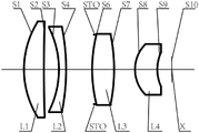
An optical lens according to embodiment 1 of the present application is described below with reference to fig. 1. Fig. 1 shows a schematic structural diagram of an optical lens according to embodiment 1 of the present application. The left side in fig. 1 is the first side and the right side is the second side.
As shown in fig. 1, the optical lens includes, in order from a first side to a second side along an optical axis, a first lens L1, a second lens L2, a third lens L3, and a fourth lens L4.
The first lens L1 is a convex-concave lens with positive refractive power, and has a convex first side S1 and a concave second side S2. The second lens L2 is a concave-convex lens with negative power, and has a concave first side S3 and a convex second side S4. The third lens L3 is a convex-concave lens with positive refractive power, and has a convex first side S6 and a concave second side S7. The fourth lens L4 is a convex-concave lens having positive refractive power, and has a convex first side S8 and a concave second side S9.
In the case where the optical lens is used as a projection lens, the optical lens includes the light emission source surface S10 on the second side. A prism and/or a field lens may be further provided in a second side direction of the fourth lens L4. The prism is used for transiting the illumination end and the imaging end of the projection lens; the field lens can correct aberration and improve the capability of marginal beam incidence.
The optical lens may further include a stop STO, which may be disposed between the second lens L2 and the third lens L3 to improve image quality. For example, the stop STO may be disposed near the first side S6 of the third lens L3. In the case where the optical lens is used as a projection lens, the light direction of the projection lens is from the second side to the first side (reduction end to enlargement end), that is, the light from the light-emitting source X at the light-emitting source surface S10 passes through the working surface of the prism and/or field lens, and the respective surfaces S9 to S1 in this order and is finally projected on the projection object. Table 1 shows the central radius of curvature R, the thickness/interval d (it is understood that, for example, the data of the thickness/interval d of the row in which S2 is located is the value of the interval d2 on the optical axis from the second side surface S2 of the first lens L1 to the first side surface S3 of the second lens L2, for example, the thickness/interval d of the row in which S8 is the central thickness d8 of the fourth lens L4), the refractive index Nd, and the abbe number Vd of each lens of the optical lens of example 1.

TABLE 1
Alternatively, the optical lens may be used as an in-vehicle lens. In the case where the optical lens is used as an in-vehicle lens, the optical lens includes an imaging surface S10 on the second side. A filter and/or a protective lens may be disposed after the fourth lens L4 of the optical lens. The optical filter can be used for correcting color deviation, and the protection lens can be used for protecting the image sensing chip X on the imaging surface S10. The light from the object sequentially passes through the respective surfaces S1 to S9, and the filter and/or the protective lens, and is finally imaged on the imaging surface S10. The vehicle-mounted lens is good in imaging quality.
Example 2
An optical lens according to embodiment 2 of the present application is described below with reference to fig. 2. Fig. 2 shows a schematic structural diagram of an optical lens according to embodiment 2 of the present application.
As shown in fig. 2, the optical lens includes, in order from a first side to a second side along an optical axis, a first lens L1, a second lens L2, a third lens L3, and a fourth lens L4.
The first lens L1 is a convex-concave lens with positive refractive power, and has a convex first side S1 and a concave second side S2. The second lens L2 is a concave-convex lens with negative power, and has a concave first side S3 and a convex second side S4. The third lens L3 is a convex-concave lens with positive refractive power, and has a convex first side S6 and a concave second side S7. The fourth lens L4 is a convex-concave lens having positive refractive power, and has a convex first side S8 and a concave second side S9.
In the case where the optical lens is used as a projection lens, the optical lens includes the light emission source surface S10 on the second side. A prism and/or a field lens may be further disposed in a second side direction of the fourth lens L4. The prism is used for transiting the illumination end and the imaging end of the projection lens; the field lens can correct aberration and improve the capability of marginal beam incidence.
The optical lens may further include a stop STO, which may be disposed between the second lens L2 and the third lens L3 to improve imaging quality. For example, the stop STO may be disposed near the first side S6 of the third lens L3. In the case where the optical lens is used as a projection lens, the light direction of the projection lens is from the second side to the first side (reduction end to enlargement end), that is, the light from the light-emitting source X at the light-emitting source surface S10 passes through the working surface of the prism and/or field lens, and the respective surfaces S9 to S1 in this order and is finally projected on the projection object.
Table 2 shows the central radius of curvature R, thickness/interval d, refractive index Nd, and abbe number Vd of each lens of the optical lens of example 2.


TABLE 2
Alternatively, the optical lens may be used as an in-vehicle lens. In the case where the optical lens is used as an in-vehicle lens, the optical lens includes an imaging surface S10 on the second side. A filter and/or a protective lens may be disposed after the fourth lens L4 of the optical lens. The optical filter can be used for correcting color deviation, and the protection lens can be used for protecting the image sensing chip X on the imaging surface S10. Light from the object sequentially passes through the surfaces S1 to S9, and the filter and/or the protective lens, and is finally imaged on the imaging surface S10.
Example 3
An optical lens according to embodiment 3 of the present application is described below with reference to fig. 3. Fig. 3 shows a schematic structural diagram of an optical lens according to embodiment 3 of the present application.
As shown in fig. 3, the optical lens includes, in order from a first side to a second side along an optical axis, a first lens L1, a second lens L2, a third lens L3, and a fourth lens L4.
The first lens L1 is a convex-concave lens with positive refractive power, and has a convex first side S1 and a concave second side S2. The second lens L2 is a concave-convex lens with negative power, and has a concave first side S3 and a convex second side S4. The third lens L3 is a convex-concave lens with positive refractive power, and has a convex first side S6 and a concave second side S7. The fourth lens L4 is a convex-concave lens having positive refractive power, and has a convex first side S8 and a concave second side S9. For example, in embodiment 3, the first side S1 of the first lens L1 to the second side S9 of the fourth lens L4 may be aspheric, and the profile x of each aspheric lens may be defined by, but is not limited to, formula (1).
In the case where the optical lens is used as a projection lens, the optical lens includes the light emission source surface S10 on the second side. A prism and/or a field lens may be further provided in a second side direction of the fourth lens L4. The prism is used for transiting the illumination end and the imaging end of the projection lens; the field lens can correct aberration and improve the capability of marginal beam incidence.
The optical lens may further include a stop STO, which may be disposed between the second lens L2 and the third lens L3 to improve image quality. For example, the stop STO may be disposed near the first side S6 of the third lens L3. In the case where the optical lens is used as a projection lens, the light direction of the projection lens is from the second side to the first side (reduction end to enlargement end), that is, the light from the light-emitting source X at the light-emitting source surface S10 passes through the working surface of the prism and/or field lens, and the respective surfaces S9 to S1 in this order and is finally projected on the projection object.
Table 3 shows the central radius of curvature R, thickness/interval d, refractive index Nd, and abbe number Vd of each lens of the optical lens of example 3.


TABLE 3
Alternatively, the optical lens may be used as an in-vehicle lens. In the case where the optical lens is used as an in-vehicle lens, the optical lens includes an imaging surface S10 on the second side. A filter and/or a protective lens may be disposed after the fourth lens L4 of the optical lens. The optical filter can be used for correcting color deviation, and the protection lens can be used for protecting the image sensing chip X on the imaging surface S10. The light from the object sequentially passes through the respective surfaces S1 to S9, and the filter and/or the protective lens, and is finally imaged on the imaging surface S10. The vehicle-mounted lens has good imaging quality.
Example 4
An optical lens according to embodiment 4 of the present application is described below with reference to fig. 4. Fig. 4 shows a schematic structural diagram of an optical lens according to embodiment 4 of the present application.
As shown in fig. 4, the optical lens includes, in order from a first side to a second side along an optical axis, a first lens L1, a second lens L2, a third lens L3, and a fourth lens L4.
The first lens L1 is a convex-concave lens with positive refractive power, and has a convex first side S1 and a concave second side S2. The second lens L2 is a concave-convex lens with negative power, and has a concave first side S3 and a convex second side S4. The third lens L3 is a double-convex lens having positive refractive power, and has a convex first side surface S6 and a convex second side surface S7. The fourth lens L4 is a convex-concave lens having positive refractive power, and has a convex first side S8 and a concave second side S9.
In the case where the optical lens is used as a projection lens, the optical lens includes the light emission source surface S10 on the second side. A prism and/or a field lens may be further disposed in a second side direction of the fourth lens L4. The prism is used for transiting the illumination end and the imaging end of the projection lens; the field lens can correct aberration and improve the capability of marginal beam incidence.
The optical lens may further include a stop STO, which may be disposed between the second lens L2 and the third lens L3 to improve imaging quality. For example, the stop STO may be disposed near the second side S4 of the second lens L2. In the case where the optical lens is used as a projection lens, the light direction of the projection lens is from the second side to the first side (reduction end to enlargement end), that is, the light from the light-emitting source X at the light-emitting source surface S10 passes through the working surface of the prism and/or field lens, and the respective surfaces S9 to S1 in this order and is finally projected on the projection object.
Table 4 shows the central radius of curvature R, thickness/interval d, refractive index Nd, and abbe number Vd of each lens of the optical lens of example 4.


TABLE 4
Alternatively, the optical lens may be used as an in-vehicle lens. In the case where the optical lens is used as an in-vehicle lens, the optical lens includes an imaging surface S10 on the second side. A filter and/or a protective lens may be disposed after the fourth lens L4 of the optical lens. The optical filter can be used for correcting color deviation, and the protection lens can be used for protecting the image sensing chip X on the imaging surface S10. The light from the object sequentially passes through the respective surfaces S1 to S9, and the filter and/or the protective lens, and is finally imaged on the imaging surface S10. The vehicle-mounted lens has good imaging quality.
Example 5
An optical lens according to embodiment 5 of the present application is described below with reference to fig. 5. Fig. 5 shows a schematic structural diagram of an optical lens according to embodiment 5 of the present application. As shown in fig. 5, the optical lens includes, in order from a first side to a second side along an optical axis, a first lens L1, a second lens L2, a third lens L3, and a fourth lens L4.
The first lens L1 is a convex-concave lens with positive refractive power, and has a convex first side S1 and a concave second side S2. The second lens L2 is a concave-convex lens with negative power, and has a concave first side S3 and a convex second side S4. The third lens L3 is a double-convex lens having positive refractive power, and has a convex first side surface S6 and a convex second side surface S7. The fourth lens L4 is a convex-concave lens having positive refractive power, and has a convex first side S8 and a concave second side S9. For example, in embodiment 5, the first side S1 of the first lens L1 to the second side S9 of the fourth lens L4 may be aspheric, and the profile x of each aspheric lens may be defined by, but is not limited to, formula (1).
In the case where the optical lens is used as a projection lens, the optical lens includes the light emission source surface S10 on the second side. A prism and/or a field lens may be further disposed in a second side direction of the fourth lens L4. The prism is used for transiting the illumination end and the imaging end of the projection lens; the field lens can correct aberration and improve the capability of marginal beam incidence.
The optical lens may further include a stop STO, which may be disposed between the second lens L2 and the third lens L3 to improve imaging quality. For example, the stop STO may be disposed near the first side S6 of the third lens L3. In the case where the optical lens is used as a projection lens, the light direction of the projection lens is from the second side to the first side (reduction end to enlargement end), that is, the light from the light-emitting source X at the light-emitting source surface S10 passes through the working surface of the prism and/or field lens, and the respective surfaces S9 to S1 in this order and is finally projected on the projection object.
Table 5 shows the central radius of curvature R, thickness/interval d, refractive index Nd, and abbe number Vd of each lens of the optical lens of example 5.


TABLE 5
Alternatively, the optical lens may be used as an in-vehicle lens. In the case where the optical lens is used as an in-vehicle lens, the optical lens includes an imaging surface S10 on the second side. A filter and/or a protective lens may be disposed after the fourth lens L4 of the optical lens. The optical filter can be used for correcting color deviation, and the protection lens can be used for protecting the image sensing chip X on the imaging surface S10. The light from the object sequentially passes through the respective surfaces S1 to S9, and the filter and/or the protective lens, and is finally imaged on the imaging surface S10. The vehicle-mounted lens has good imaging quality.
Example 6
An optical lens according to embodiment 6 of the present application is described below with reference to fig. 6. Fig. 6 shows a schematic structural diagram of an optical lens according to embodiment 6 of the present application. As shown in fig. 6, the optical lens includes, in order from a first side to a second side along an optical axis, a first lens L1, a second lens L2, a third lens L3, and a fourth lens L4.
The first lens L1 is a convex-concave lens with positive refractive power, and has a convex first side S1 and a concave second side S2. The second lens L2 is a concave-convex lens with negative power, and has a concave first side S3 and a convex second side S4. The third lens L3 is a double-convex lens having positive refractive power, and has a convex first side surface S6 and a convex second side surface S7. The fourth lens L4 is a convex-concave lens having positive refractive power, and has a convex first side S8 and a concave second side S9. For example, in embodiment 6, the first side S1 of the first lens L1 to the second side S9 of the fourth lens L4 may each be an aspheric surface, and the profile x of each aspheric lens may be defined by, but is not limited to, formula (1).
In the case where the optical lens is used as a projection lens, the optical lens includes the light emission source surface S10 on the second side. A prism and/or a field lens may be further provided in a second side direction of the fourth lens L4. The prism is used for transiting the illumination end and the imaging end of the projection lens; the field lens can correct aberration and improve the capability of marginal beam incidence.
The optical lens may further include a stop STO, which may be disposed between the second lens L2 and the third lens L3 to improve image quality. For example, the stop STO may be disposed near the first side S6 of the third lens L3. In the case where the optical lens is used as a projection lens, the light direction of the projection lens is from the second side to the first side (reduction end to enlargement end), that is, the light from the light-emitting source X at the light-emitting source surface S10 passes through the working surface of the prism and/or field lens, and the respective surfaces S9 to S1 in this order and is finally projected on the projection object.
Table 6 shows the central radius of curvature R, thickness/interval d, refractive index Nd, and abbe number Vd of each lens of the optical lens of example 6.

TABLE 6
Alternatively, the optical lens may be used as an in-vehicle lens. In the case where the optical lens is used as an in-vehicle lens, the optical lens includes an imaging surface S10 on the second side. A filter and/or a protective lens may be disposed after the fourth lens L4 of the optical lens. The optical filter can be used for correcting color deviation, and the protection lens can be used for protecting the image sensing chip X on the imaging surface S10. The light from the object sequentially passes through the respective surfaces S1 to S9, and the filter and/or the protective lens, and is finally imaged on the imaging surface S10. The vehicle-mounted lens has good imaging quality.
In summary, examples 1 to 6 satisfy the parameters/relationships shown in table 7 and table 8 below, respectively. In table 7, TTL, F, EPDI, F1, F2, F3, F4, Φ 1, Φ 2, Φ 3, and Φ 4 are in units of millimeters (mm), and FOV is in units of degrees (°).

TABLE 7


TABLE 8
The present application also provides an electronic device that may include the optical lens according to the above-described embodiment of the present application and a light emitting source for converting an electrical signal into an optical signal, which forms an image via the optical lens. The light source can be arranged on the light source surface of the optical lens. Illustratively, the light emitting source may be an emitting terminal such as an LED chip. Illustratively, the light-emitting source may include a reflective screen or the like that forms an optical signal based on the light emitted from the light source.
The electronic device may be a projection module, such as on a searchlight device. Furthermore, the electronic device may also be a stand-alone imaging device, such as an onboard DLP headlamp, or a projection module integrated on, for example, an intelligent driving system.
The present application also provides an electronic device that may include the optical lens according to the above-described embodiment of the present application and an imaging element for converting an optical image formed by the optical lens into an electrical signal. Illustratively, the electronic device includes an imaging element disposed on an imaging surface of the optical lens. Alternatively, the imaging element provided on the imaging plane may be a photo-coupled device (CCD) or a Complementary Metal Oxide Semiconductor (CMOS).
The electronic device may be a stand-alone electronic device such as a range finding camera or may be an imaging module integrated on a device such as a range finding device. In addition, the electronic device may also be a separate imaging device such as a vehicle-mounted camera, or may be an imaging module integrated on a system such as a driving assistance system.
The above description is only a preferred embodiment of the application and is illustrative of the principles of the technology employed. It will be appreciated by a person skilled in the art that the scope of the invention according to the present application is not limited to the specific combination of the above-mentioned features, but also covers other embodiments where any combination of the above-mentioned features or their equivalents is made without departing from the inventive concept. For example, the above features may be replaced with (but not limited to) features having similar functions disclosed in the present application.
Claims (34)
1. An optical lens assembly, sequentially comprising along an optical axis from a first side to a second side:
a first lens having a positive refractive power, a first side surface of which is convex and a second side surface of which is concave;
a second lens with negative focal power, wherein the first side surface of the second lens is a concave surface, and the second side surface of the second lens is a convex surface;
a third lens having positive focal power, a first side surface of which is a convex surface; and
a fourth lens having a positive refractive power, the first side surface of which is convex and the second side surface of which is concave,
the maximum clear aperture phi 1 of the first lens, the maximum clear aperture phi 2 of the second lens, the maximum clear aperture phi 3 of the third lens and the maximum clear aperture phi 4 of the fourth lens satisfy: phi 1 is more than or equal to phi 2 is more than or equal to phi 3 is more than or equal to phi 4, an
The number of lenses having power in the optical lens is four.
2. An optical lens barrel according to claim 1, wherein the second side surface of the third lens is concave.
3. An optical lens barrel according to claim 1, wherein the second side surface of the third lens is convex.
4. An optical lens according to any one of claims 1 to 3, wherein the total optical length TTL of the optical lens and the total effective focal length F of the optical lens satisfy: TTL/F is less than or equal to 4.5.
5. An optical lens as claimed in any one of claims 1 to 3, characterized in that the total effective focal length F of the optical lens and the entrance pupil diameter EPDI of the optical lens satisfy: F/EPDI is less than or equal to 1.2.
6. An optical lens according to any one of claims 1 to 3, characterized in that the effective focal length F1 of the first lens and the effective focal length F2 of the second lens satisfy: the ratio of F1 to F2 is less than or equal to 4.
7. An optical lens according to any one of claims 1 to 3, characterized in that the effective focal length F2 of the second lens and the effective focal length F3 of the third lens satisfy: the ratio of F3 to F2 is less than or equal to 4.
8. An optical lens according to any one of claims 1 to 3, characterized in that the effective focal length F1 of the first lens and the effective focal length F3 of the third lens satisfy: F1/F3 is less than or equal to 4.5.
9. An optical lens according to any one of claims 1 to 3, characterized in that the effective focal length F2 of the second lens and the total effective focal length F of the optical lens satisfy: and the ratio of F2/F is more than or equal to 1.8.
10. An optical lens according to any one of claims 1 to 3, characterized in that the effective focal length F4 of the fourth lens and the total effective focal length F of the optical lens satisfy: F4/F is less than or equal to 5.
11. An optical lens according to any one of claims 1 to 3, characterized in that the effective focal length F3 of the third lens and the effective focal length F4 of the fourth lens satisfy: F3/F4 is less than or equal to 5.
12. An optical lens according to any one of claims 1 to 3, characterized in that the central radius of curvature R3 of the first side surface of the second lens, the central radius of curvature R4 of the second side surface of the second lens, and the central thickness d3 of the second lens on the optical axis satisfy: R3/(R4+ d3) is less than or equal to 2.
13. An optical lens according to any one of claims 1 to 3, characterized in that a center radius of curvature R8 of a first side surface of the fourth lens, a center radius of curvature R9 of a second side surface of the fourth lens, and a center thickness d8 of the fourth lens on the optical axis satisfy: R8/(R9+ d8) is less than or equal to 1.5.
14. An optical lens according to any one of claims 1 to 3, characterized in that the back focal length BFL of the optical lens and the total effective focal length F of the optical lens satisfy: BFL/F is less than or equal to 0.5.
15. An optical lens according to any one of claims 1 to 3, characterized in that the effective focal length F1 of the first lens and the distance d2 on the optical axis from the second side of the first lens to the first side of the second lens satisfy: f1/d2 is more than or equal to 3.
16. An optical lens according to any one of claims 1 to 3, characterized in that in each field of view of the optical lens, the angle of each ray in the exit pupil of the first side of the first lens with the chief ray is the exit angle of the first lens, the value of the exit angle of the first lens being not more than 1 °.
17. The optical lens assembly, along the optical axis, comprises in order from a first side to a second side:
the first lens with positive focal power, its first side is the convex surface;
a second lens with negative focal power, wherein the first side surface of the second lens is a concave surface, and the second side surface of the second lens is a convex surface;
a third lens having a positive optical power; and
a fourth lens having a positive refractive power, a convex first side surface and a concave second side surface;
wherein the total effective focal length F of the optical lens and the entrance pupil diameter EPDI of the optical lens satisfy: F/EPDI is less than or equal to 1.2,
the maximum clear aperture phi 1 of the first lens, the maximum clear aperture phi 2 of the second lens, the maximum clear aperture phi 3 of the third lens and the maximum clear aperture phi 4 of the fourth lens satisfy: phi 1 is more than or equal to phi 2 is more than or equal to phi 3 is more than or equal to phi 4, an
The number of lenses having optical power in the optical lens is four.
18. An optical lens barrel according to claim 17, wherein the second side surface of the first lens is concave.
19. An optical lens barrel according to claim 17, wherein the first side of the third lens is convex.
20. An optical lens barrel according to claim 19, wherein the second side surface of the third lens is concave.
21. An optical lens barrel according to claim 19, wherein the second side of the third lens is convex.
22. An optical lens according to any one of claims 17 to 21, wherein the total optical length TTL of the optical lens and the total effective focal length F of the optical lens satisfy: TTL/F is less than or equal to 4.5.
23. An optical lens as claimed in any one of claims 17 to 21, characterized in that the effective focal length F1 of the first lens and the effective focal length F2 of the second lens satisfy: the ratio of F1/F2 is less than or equal to 4.
24. An optical lens element according to any of claims 17 to 21, characterized in that the effective focal length F2 of the second lens and the effective focal length F3 of the third lens satisfy: the ratio of F3/F2 is less than or equal to 4.
25. An optical lens as claimed in any one of claims 17 to 21, characterized in that the effective focal length F1 of the first lens and the effective focal length F3 of the third lens satisfy: F1/F3 is less than or equal to 4.5.
26. An optical lens according to any one of claims 17 to 21, characterized in that the effective focal length F2 of the second lens and the total effective focal length F of the optical lens satisfy: and the | F2/F | is more than or equal to 1.8.
27. An optical lens according to any one of claims 17 to 21, characterized in that the effective focal length F4 of the fourth lens and the total effective focal length F of the optical lens satisfy: F4/F is less than or equal to 5.
28. An optical lens element according to any one of claims 17 to 21, characterized in that the effective focal length F3 of the third lens and the effective focal length F4 of the fourth lens satisfy: F3/F4 is less than or equal to 5.
29. An optical lens according to any one of claims 17 to 21, characterized in that the central radius of curvature R3 of the first side surface of the second lens, the central radius of curvature R4 of the second side surface of the second lens, and the central thickness d3 of the second lens on the optical axis satisfy: R3/(R4+ d3) is less than or equal to 2.
30. An optical lens according to any one of claims 17 to 21, characterized in that a central radius of curvature R8 of a first side surface of the fourth lens, a central radius of curvature R9 of a second side surface of the fourth lens, and a central thickness d8 of the fourth lens on the optical axis satisfy: R8/(R9+ d8) is less than or equal to 1.5.
31. An optical lens according to any of claims 17 to 21, characterized in that the back focal length BFL of the optical lens and the total effective focal length F of the optical lens satisfy: BFL/F is less than or equal to 0.5.
32. An optical lens element according to any one of claims 17 to 21, characterized in that the effective focal length F1 of the first lens and the distance d2 on the optical axis from the second side of the first lens to the first side of the second lens satisfy: f1/d2 is more than or equal to 3.
33. An optical lens element according to any one of claims 17 to 21, characterized in that in each field of view of the optical lens element the angle of each ray in the exit pupil of the first side of the first lens with the chief ray is the exit angle of the first lens, the exit angle of the first lens having a value not greater than 1 °.
34. An electronic apparatus comprising the optical lens according to claim 1 or 17 and a light emission source for converting an electric signal into an optical signal, the optical signal forming an image via the optical lens; or,
comprising an optical lens according to claim 1 or 17 and an imaging element for converting an optical image formed by the optical lens into an electrical signal.
Priority Applications (1)
| Application Number | Priority Date | Filing Date | Title |
|---|---|---|---|
| CN202010401156.6A CN113671663B (en) | 2020-05-13 | 2020-05-13 | Optical lens and electronic device |
Applications Claiming Priority (1)
| Application Number | Priority Date | Filing Date | Title |
|---|---|---|---|
| CN202010401156.6A CN113671663B (en) | 2020-05-13 | 2020-05-13 | Optical lens and electronic device |
Publications (2)
| Publication Number | Publication Date |
|---|---|
| CN113671663A CN113671663A (en) | 2021-11-19 |
| CN113671663B true CN113671663B (en) | 2022-09-09 |
Family
ID=78536941
Family Applications (1)
| Application Number | Title | Priority Date | Filing Date |
|---|---|---|---|
| CN202010401156.6A Active CN113671663B (en) | 2020-05-13 | 2020-05-13 | Optical lens and electronic device |
Country Status (1)
| Country | Link |
|---|---|
| CN (1) | CN113671663B (en) |
Families Citing this family (2)
| Publication number | Priority date | Publication date | Assignee | Title |
|---|---|---|---|---|
| CN116540386B (en) * | 2023-06-02 | 2025-07-29 | 深圳市韵腾激光科技有限公司 | High-power objective lens for laser cutting |
| CN119665171A (en) * | 2024-12-27 | 2025-03-21 | 常州星宇车灯股份有限公司 | An optical structure for self-closing loop vehicle lights |
Citations (4)
| Publication number | Priority date | Publication date | Assignee | Title |
|---|---|---|---|---|
| CN1940628A (en) * | 2005-09-29 | 2007-04-04 | 富士能株式会社 | Image-forming lens |
| CN102213821A (en) * | 2011-06-24 | 2011-10-12 | 浙江舜宇光学有限公司 | Near infrared lens |
| CN208721876U (en) * | 2018-09-05 | 2019-04-09 | 西安泰豪红外科技有限公司 | A Large Aperture Ultra High Resolution Infrared Lens |
| CN110908097A (en) * | 2019-12-24 | 2020-03-24 | 协益电子(苏州)有限公司 | Optical lens, camera optical device and vehicle-mounted monitoring camera |
Family Cites Families (1)
| Publication number | Priority date | Publication date | Assignee | Title |
|---|---|---|---|---|
| JP4828317B2 (en) * | 2005-09-29 | 2011-11-30 | 富士フイルム株式会社 | Imaging lens |
-
2020
- 2020-05-13 CN CN202010401156.6A patent/CN113671663B/en active Active
Patent Citations (4)
| Publication number | Priority date | Publication date | Assignee | Title |
|---|---|---|---|---|
| CN1940628A (en) * | 2005-09-29 | 2007-04-04 | 富士能株式会社 | Image-forming lens |
| CN102213821A (en) * | 2011-06-24 | 2011-10-12 | 浙江舜宇光学有限公司 | Near infrared lens |
| CN208721876U (en) * | 2018-09-05 | 2019-04-09 | 西安泰豪红外科技有限公司 | A Large Aperture Ultra High Resolution Infrared Lens |
| CN110908097A (en) * | 2019-12-24 | 2020-03-24 | 协益电子(苏州)有限公司 | Optical lens, camera optical device and vehicle-mounted monitoring camera |
Also Published As
| Publication number | Publication date |
|---|---|
| CN113671663A (en) | 2021-11-19 |
Similar Documents
| Publication | Publication Date | Title |
|---|---|---|
| CN111999863B (en) | Optical lens and imaging apparatus | |
| CN111239962B (en) | Optical lens and imaging apparatus | |
| CN116774390B (en) | Optical lenses and electronic devices | |
| CN115616731B (en) | Optical lenses and electronic devices | |
| CN114280758B (en) | Optical lens and electronic device | |
| CN114280756B (en) | Optical lens and electronic device | |
| CN114509859B (en) | Optical lens and electronic device | |
| CN111830672A (en) | Optical lens and imaging apparatus | |
| CN114859502A (en) | Optical lens and electronic device | |
| CN116224534A (en) | Optical lenses and electronic equipment | |
| CN113448057A (en) | Optical lens and electronic device | |
| CN112748555A (en) | Optical lens and electronic device | |
| CN113671663B (en) | Optical lens and electronic device | |
| CN118276277A (en) | Optical lens and electronic device | |
| CN113267870A (en) | Optical lens and electronic device | |
| CN119395859B (en) | Optical lenses and electronic equipment | |
| CN119024537B (en) | Optical lens and electronic device | |
| CN114063246B (en) | Optical lens and electronic device | |
| CN119247599A (en) | Optical lenses and electronic equipment | |
| CN117950151B (en) | Optical lenses and electronic devices | |
| CN116203699B (en) | Optical lens and electronic device | |
| CN116953885B (en) | Optical lenses and electronic devices containing them | |
| CN115437105B (en) | Optical lenses and electronic equipment | |
| CN118276286A (en) | Optical lens and electronic device | |
| CN117289426A (en) | Optical lens and electronic device |
Legal Events
| Date | Code | Title | Description |
|---|---|---|---|
| PB01 | Publication | ||
| PB01 | Publication | ||
| SE01 | Entry into force of request for substantive examination | ||
| SE01 | Entry into force of request for substantive examination | ||
| GR01 | Patent grant | ||
| GR01 | Patent grant |