CN113649874A - Polishing device and method for hardware manufacturing and capable of conveniently adjusting polishing degree - Google Patents
Polishing device and method for hardware manufacturing and capable of conveniently adjusting polishing degree Download PDFInfo
- Publication number
- CN113649874A CN113649874A CN202110944539.2A CN202110944539A CN113649874A CN 113649874 A CN113649874 A CN 113649874A CN 202110944539 A CN202110944539 A CN 202110944539A CN 113649874 A CN113649874 A CN 113649874A
- Authority
- CN
- China
- Prior art keywords
- fixedly connected
- sliding
- gear
- polishing
- plate
- Prior art date
- Legal status (The legal status is an assumption and is not a legal conclusion. Google has not performed a legal analysis and makes no representation as to the accuracy of the status listed.)
- Withdrawn
Links
Images


Classifications
-
- B—PERFORMING OPERATIONS; TRANSPORTING
- B24—GRINDING; POLISHING
- B24B—MACHINES, DEVICES, OR PROCESSES FOR GRINDING OR POLISHING; DRESSING OR CONDITIONING OF ABRADING SURFACES; FEEDING OF GRINDING, POLISHING, OR LAPPING AGENTS
- B24B7/00—Machines or devices designed for grinding plane surfaces on work, including polishing plane glass surfaces; Accessories therefor
- B24B7/10—Single-purpose machines or devices
-
- B—PERFORMING OPERATIONS; TRANSPORTING
- B24—GRINDING; POLISHING
- B24B—MACHINES, DEVICES, OR PROCESSES FOR GRINDING OR POLISHING; DRESSING OR CONDITIONING OF ABRADING SURFACES; FEEDING OF GRINDING, POLISHING, OR LAPPING AGENTS
- B24B41/00—Component parts such as frames, beds, carriages, headstocks
- B24B41/02—Frames; Beds; Carriages
-
- B—PERFORMING OPERATIONS; TRANSPORTING
- B24—GRINDING; POLISHING
- B24B—MACHINES, DEVICES, OR PROCESSES FOR GRINDING OR POLISHING; DRESSING OR CONDITIONING OF ABRADING SURFACES; FEEDING OF GRINDING, POLISHING, OR LAPPING AGENTS
- B24B41/00—Component parts such as frames, beds, carriages, headstocks
- B24B41/06—Work supports, e.g. adjustable steadies
-
- B—PERFORMING OPERATIONS; TRANSPORTING
- B24—GRINDING; POLISHING
- B24B—MACHINES, DEVICES, OR PROCESSES FOR GRINDING OR POLISHING; DRESSING OR CONDITIONING OF ABRADING SURFACES; FEEDING OF GRINDING, POLISHING, OR LAPPING AGENTS
- B24B47/00—Drives or gearings; Equipment therefor
- B24B47/02—Drives or gearings; Equipment therefor for performing a reciprocating movement of carriages or work- tables
- B24B47/04—Drives or gearings; Equipment therefor for performing a reciprocating movement of carriages or work- tables by mechanical gearing only
-
- B—PERFORMING OPERATIONS; TRANSPORTING
- B24—GRINDING; POLISHING
- B24B—MACHINES, DEVICES, OR PROCESSES FOR GRINDING OR POLISHING; DRESSING OR CONDITIONING OF ABRADING SURFACES; FEEDING OF GRINDING, POLISHING, OR LAPPING AGENTS
- B24B47/00—Drives or gearings; Equipment therefor
- B24B47/10—Drives or gearings; Equipment therefor for rotating or reciprocating working-spindles carrying grinding wheels or workpieces
- B24B47/12—Drives or gearings; Equipment therefor for rotating or reciprocating working-spindles carrying grinding wheels or workpieces by mechanical gearing or electric power
Landscapes
- Engineering & Computer Science (AREA)
- Mechanical Engineering (AREA)
- Grinding And Polishing Of Tertiary Curved Surfaces And Surfaces With Complex Shapes (AREA)
Abstract
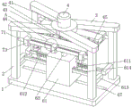
The invention relates to the technical field of hardware manufacturing, in particular to a polishing device for hardware manufacturing, which is convenient for adjusting polishing degree and comprises a base, wherein supporting columns are fixedly connected to four corners of the upper surface of the base, an installation frame is fixedly connected to the tops of the supporting columns, an adjusting assembly is installed in the middle of the installation frame, a clamping assembly is installed on the adjusting assembly, and a polishing assembly is arranged in the middle of the upper surface of the base. According to the metal plate polishing device, the rotating shaft is driven to rotate by the starting motor, the rotating shaft can drive the polishing plate to rotate in the rotating process, the metal plate can be polished by the polishing plate in the rotating process, the rotating shaft can also drive the half gear to rotate in the rotating process, the half gear can reciprocate left and right with the rotating shaft through the matching of the racks in the rotating process, the polishing range of the metal plate by the polishing plate is widened, and the polishing efficiency of the metal plate is improved.
Description
Technical Field
The invention relates to the technical field of hardware manufacturing, in particular to a polishing device for hardware manufacturing, which is convenient for adjusting polishing degree.
Background
The hardware processing is to process raw materials into various parts according to the drawing or sample of a customer by using machines such as a lathe, a milling machine, a drilling machine, polishing and the like, wherein the machining comprises the following steps: the metal processing such as screws, motor shafts, model car parts, fishing gear parts, loudspeaker box product shells, mobile power supply shells and the like is short for metalworking, is a process technology for processing metal materials into articles, parts and components, comprises large parts such as bridges and ships and even fine components such as engines, jewels and wristwatches, and is widely applied to different fields such as science, industry, artworks, handicraft and the like. However, most of the existing hardware grinding devices also have the following problems:
grinding device for hardware manufacturing drives the pivot and polishes the board and polish to sheet metal spare through the motor simultaneously, but, because the position of motor, pivot and polishing board is fixed, can not remove, leads to current grinding device for hardware manufacturing's the scope of polishing lower, and simultaneously, current part grinding device for hardware manufacturing is polishing the in-process, can not flexibly handle the accuse to sheet metal spare's the degree of polishing.
Therefore, it is necessary to design a polishing device for hardware manufacturing, which is convenient for adjusting the polishing degree, to solve the above problems.
Disclosure of Invention
The invention aims to provide a polishing device for hardware manufacturing, which is convenient for adjusting polishing degree and aims to solve the problems in the background technology.
In order to achieve the purpose, the invention provides the following technical scheme: the utility model provides a convenient grinding device for hardware manufacturing who adjusts degree of polishing, includes the base, the equal fixedly connected with support column in upper surface four corners department of base, the top fixedly connected with mounting bracket of support column, the mid-mounting of mounting bracket has the adjustment subassembly, install the centre gripping subassembly on the adjustment subassembly, the upper surface middle part of base is provided with the subassembly of polishing.
Preferably, the adjusting assembly comprises a forward and reverse rotating motor, a rotating rod, a gear, a sliding plate and a gear strip, the forward and reverse rotating motor is fixedly installed in the middle of the installation frame, the top end of the rotating rod is fixed with the output end of the forward and reverse rotating motor, the bottom end of the rotating rod penetrates through the middle of the installation frame and is fixedly connected with the gear, the gear strip is fixedly installed on the sliding plate, and the gear is meshed with the gear strip and is connected with the gear strip.
Preferably, wherein two the support column and two in addition be provided with slide mechanism between the support column, slide mechanism includes slide bar, sliding block, two fixed blocks the both ends of slide bar respectively with two support column fixed connection, two the fixed block symmetry is fixed on the slide bar, the sliding block is located between two fixed blocks, sliding block fixed connection is in the middle part of one side that the gear was kept away from to the sliding plate, the round hole with slide bar looks adaptation is seted up at the middle part of sliding block, the sliding block passes through round hole sliding connection on the slide bar.
Preferably, a cross sliding groove is formed in the middle of one side, away from the gear, of the sliding plate, a cross sliding block matched with the cross sliding groove is fixedly connected to one side, close to the gear, of the fixed block, and the cross sliding groove is connected to the cross sliding block in a sliding mode.
Preferably, the centre gripping subassembly includes U type grip block the top fixed connection of U type grip block is at the lower surface of sliding plate, the upper surface one end threaded connection of U type grip block has the screw rod, disc fixed connection is at the top of screw rod, the bottom fixedly connected with rubber pad of screw rod, the backup pad is located the inside of U type grip block, the outside of telescopic link is located to the spring housing, the one end of telescopic link and spring all with the fixed connection of the interior diapire of U type grip block, the other end of telescopic link and spring all with the bottom fixed connection of backup pad.
Preferably, a through hole is formed in the disc, a positioning pin is slidably connected in the through hole, a positioning hole matched with the positioning pin is formed in the upper surface of the U-shaped clamping plate, a T-shaped sliding groove is formed in the middle of the lower surface of the U-shaped clamping plate, a T-shaped sliding block matched with the T-shaped sliding groove is fixedly connected to the other end of the upper surface of the U-shaped clamping plate, and the T-shaped sliding block is slidably connected in the T-shaped sliding groove formed in the lower surface of the other U-shaped clamping plate.
Preferably, the subassembly of polishing includes box, motor, pivot, polishing board, semi-gear, protruding type slider and protruding type spout, motor fixed connection is on the interior diapire of box, the bottom of pivot and the output fixed connection of motor, the top of pivot run through the top middle part of box and with polishing board fixed connection, semi-gear fixed connection is on the surface of pivot, and semi-gear is located the inside of box, protruding type slider fixed connection is at the lower surface middle part of box, the upper surface middle part of base is seted up to protruding type spout, protruding type slider and protruding type spout looks adaptation, and protruding type slider sliding connection is in the inside of protruding type spout.
Preferably, two through grooves are formed in the left side face and the right side face of the box body, fixing rods are arranged in the two through grooves and the two outer through grooves, the two ends of each fixing rod are fixedly connected with cross rods respectively, the cross rods are fixedly connected to supporting columns, the fixing rods are close to a side face middle portion of the half gear and are fixedly connected with racks, and the racks are meshed with the half gear and are connected with the half gear.
Compared with the prior art, the invention has the beneficial effects that:
drive the pivot through starter motor and rotate, the pivot can drive the board of polishing at the rotation in-process and rotate, the board of polishing can polish metal sheet at the rotation in-process, the pivot can also drive the rotation of half-gear at the rotation in-process, the cooperation of half-gear through the rack at the rotation in-process, reciprocating motion about can making half-gear and pivot carry out, make the board of polishing obtain promoting to metal sheet's the scope of polishing, thereby make metal sheet's the efficiency of polishing obtain promoting.
The rotating rod is driven to rotate positively by starting a positive and negative rotation motor, the rotating rod can drive the gear to rotate in the rotating process, the gear can drive the two gear strips to move in the rotating process, the two gear strips can drive the two sliding plates to simultaneously move towards the direction close to the gear in the moving process, the sliding plates can drive the sliding blocks to slide on the sliding rods through the circular holes in the moving process, the sliding plates can slide on the cross sliding blocks through the cross sliding grooves, the sliding plates can drive the U-shaped clamping plates to move towards the direction close to the gear in the moving process, the T-shaped sliding blocks fixed by the U-shaped clamping plates are driven to slide in the T-shaped sliding grooves formed in the lower surfaces of the other U-shaped clamping plates by the U-shaped clamping plates, the distance between the two U-shaped clamping plates can be adjusted due to the movement of the two U-shaped clamping plates, metal plates with different widths can be fixed, and the screw rod is driven to rotate by the disc, can the distance between adjusting screw and the backup pad to can fix the sheet metal spare of different thickness, simultaneously because the setting of telescopic link can make sheet metal spare highly obtain adjusting, thereby realized the effect that the degree of polishing to sheet metal spare can be adjusted in a flexible way.
Drawings
FIG. 1 is a schematic perspective view of the present invention;
FIG. 2 is an enlarged schematic view of the structure at A of FIG. 1 in accordance with the present invention;
FIG. 3 is a schematic bottom perspective view of the present invention;
FIG. 4 is a perspective view of the clamping assembly of the present invention;
FIG. 5 is an enlarged schematic view of the structure at B in FIG. 4 according to the present invention;
FIG. 6 is a side cross-sectional structural view of the case of the present invention.
In the figure: 1. a base; 2. a support pillar; 3. a mounting frame; 4. an adjustment assembly; 41. a positive and negative rotation motor; 42. rotating the rod; 43. a gear; 44. a sliding plate; 441. a cross-shaped chute; 45. a gear rack; 5. a clamping assembly; 51. a U-shaped clamping plate; 511. positioning holes; 512. a T-shaped chute; 513. a T-shaped slider; 52. a screw; 53. a disc; 531. positioning pins; 54. a support plate; 55. a telescopic rod; 56. a spring; 6. polishing the assembly; 61. a box body; 611. a through groove; 612. fixing the rod; 613. a cross bar; 614. a rack; 62. a motor; 63. a rotating shaft; 64. grinding the plate; 65. a half gear; 66. a convex slider; 67. a convex chute; 7. a sliding mechanism; 71. a slide bar; 72. a slider; 73. a fixed block; 731. a crosshead shoe.
Detailed Description
The technical solutions in the embodiments of the present invention will be clearly and completely described below with reference to the drawings in the embodiments of the present invention, and it is obvious that the described embodiments are only a part of the embodiments of the present invention, and not all of the embodiments. All other embodiments, which can be derived by a person skilled in the art from the embodiments given herein without making any creative effort, shall fall within the protection scope of the present invention.
Referring to fig. 1-6, a polishing device for hardware manufacturing, which is convenient for adjusting polishing degree, comprises a base 1, wherein support columns 2 are fixedly connected to four corners of the upper surface of the base 1, a mounting frame 3 is fixedly connected to the tops of the support columns 2, an adjusting assembly 4 is installed in the middle of the mounting frame 3, a clamping assembly 5 is installed on the adjusting assembly 4, and a polishing assembly 6 is arranged in the middle of the upper surface of the base 1.
Further, as shown in fig. 1, the adjusting assembly 4 includes a forward and reverse rotation motor 41, a rotating rod 42, a gear 43, a sliding plate 44 and a gear strip 45, the forward and reverse rotation motor 41 is fixedly installed in the middle of the mounting frame 3, the mounting frame 3 supports the forward and reverse rotation motor 41, so that the forward and reverse rotation motor 41 can stably work, the top end of the rotating rod 42 is fixed to the output end of the forward and reverse rotation motor 41, the bottom end of the rotating rod 42 penetrates through the middle of the mounting frame 3 and is fixedly connected with the gear 43, the gear strip 45 is fixedly installed on the sliding plate 44, the forward and reverse rotation motor 41 can drive the rotating rod 42 and the gear 43 to rotate, the gear 43 is meshed with the gear strip 45, the gear 43 passes through the matching of the gear strip 45, the sliding plate 44 can be driven to slide, a gap is left between the sliding plate 44 and the support column 2, and the normal movement of the sliding plate 44 can be ensured.
Further, as shown in fig. 1, fig. 2, fig. 3 and fig. 4, a sliding mechanism 7 is disposed between two of the support columns 2 and the other two support columns 2, the sliding mechanism 7 includes a sliding rod 71, a sliding block 72, two fixing blocks 73, two ends of the sliding rod 71 are respectively and fixedly connected to the two support columns 2, the two fixing blocks 73 are symmetrically fixed on the sliding rod 71, the sliding block 72 is located between the two fixing blocks 73, the sliding block 72 is fixedly connected to the middle portion of one side of the sliding plate 44 away from the gear 43, a circular hole matched with the sliding rod 71 is formed in the middle portion of the sliding block 72, the sliding block 72 is slidably connected to the sliding rod 71 through the circular hole, through the arrangement of the sliding mechanism 7, not only can the movement of the sliding plate 44 be satisfied, but also a supporting effect can be exerted on the sliding plate 44, and the sliding plate 44 is prevented from being in a suspended state.
Further, as shown in fig. 1, 2 and 4, a cross sliding groove 441 is formed in the middle of one side of the sliding plate 44, which is far away from the gear 43, a cross sliding block 731, which is matched with the cross sliding groove 441, is fixedly connected to one side of the fixed block 73, which is close to the gear 43, the cross sliding groove 441 is slidably connected to the cross sliding block 731, and the movement of the sliding plate 44 can be more stable through the matching arrangement of the cross sliding block 731 and the cross sliding groove 441, so that the sliding plate 44 is prevented from being inclined in the moving process.
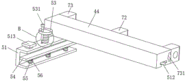
Further, as shown in fig. 3, fig. 4 and fig. 5, the clamping assembly 5 includes a U-shaped clamping plate 51, the top of the U-shaped clamping plate 51 is fixedly connected to the lower surface of the sliding plate 44, one end of the upper surface of the U-shaped clamping plate 51 is connected to the screw 52 in a threaded manner, the disc 53 is fixedly connected to the top of the screw 52, the disc 53 facilitates the user to rotate the screw 52, the bottom end of the screw 52 is fixedly connected to a rubber pad, the rubber pad can prevent the screw 52 from directly contacting with a metal plate to be polished, so as to protect the metal plate to be polished, the supporting plate 54 is located inside the U-shaped clamping plate 51, the spring 56 is sleeved outside the telescopic rod 55, one ends of the telescopic rod 55 and the spring 56 are both fixedly connected to the inner bottom wall of the U-shaped clamping plate 51, and the other ends of the telescopic rod 55 and the spring 56 are both fixedly connected to the bottom of the supporting plate 54.
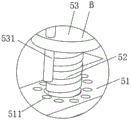
Further, as shown in fig. 4 and 5, a through hole is formed in the disc 53, a positioning pin 531 is slidably connected in the through hole, a positioning hole 511 adapted to the positioning pin 531 is formed in the upper surface of the U-shaped clamping plate 51, a plurality of positioning holes 511 are provided, the plurality of positioning holes 511 are distributed in an annular array with respect to the screw 52, a gap is left between each positioning hole 511 and the screw 52, the position of the disc 53 can be fixed under the cooperation between the positioning pin 531 and the positioning hole 511, so that the disc 53 and the screw 52 can be rotated due to the disc 53 being accidentally touched after the screw 52 is fixed, the position of the screw 52 is more firmly fixed, a T-shaped sliding groove 512 is formed in the middle of the lower surface of the U-shaped clamping plate 51, a T-shaped sliding block 513 adapted to the T-shaped sliding groove 512 is fixedly connected to the other end of the upper surface of the U-shaped clamping plate 51, the T-shaped sliding block 513 is slidably connected in a T-shaped sliding groove 512 formed in the lower surface of the other U-shaped clamping plate 51, through the cooperation of T type slider 513 and T type spout 512, can enough make U type grip block 51 keep away from the other end of sliding plate 44 and be supported by another sliding plate 44, prevent that U type grip block 51 from appearing unsettled state, can satisfy again, U type grip block 51's removal.
Further, as shown in fig. 1, 3 and 6, the polishing assembly 6 includes a box 61, a motor 62, a rotating shaft 63, a polishing plate 64, a half gear 65, a convex slider 66 and a convex sliding slot 67, the motor 62 is fixedly connected to the inner bottom wall of the box 61, the bottom end of the rotating shaft 63 is fixedly connected to the output end of the motor 62, the top end of the rotating shaft 63 penetrates through the middle of the top end of the box 61 and is fixedly connected to the polishing plate 64, the half gear 65 is fixedly connected to the outer surface of the rotating shaft 63, the half gear 65 is positioned in the box body 61, the convex slide block 66 is fixedly connected with the middle part of the lower surface of the box body 61, the convex slide groove 67 is arranged at the middle part of the upper surface of the base 1, the convex slide block 66 is matched with the convex slide groove 67, the convex slide block 66 is connected with the inner part of the convex slide groove 67 in a sliding way, the convex slider 66 and the convex runner 67 are provided in cooperation with each other, so that the movement of the case 61 can be guided.
Further, as shown in fig. 1, fig. 2 and fig. 6, two through grooves 611 are formed in the left side surface and the right side surface of the box body 61, wherein fixing rods 612 are arranged inside the two through grooves 611 and the two outer through grooves 611, two ends of each fixing rod 612 are respectively and fixedly connected with a cross rod 613, the cross rods 613 are fixedly connected to the supporting columns 2, a rack 614 is fixedly connected to the middle of one side surface of each fixing rod 612 close to the half gear 65, the rack 614 is meshed with the half gear 65 and connected with the half gear, and the box body 61 can be moved through the through grooves 611.
The working principle is as follows: when the polishing device is used, a metal plate to be polished is placed in the two U-shaped clamping plates 51, the upper surface of the supporting plate 54 is in contact with the lower surface of the metal plate, the metal plate is supported by the supporting plate 54, then the screw 52 is rotated forwardly through the disc 53, as the screw 52 is in threaded connection with the U-shaped clamping plates 51, the screw 52 can move downwards in the rotating process until the rubber pad at the bottom end of the screw 52 is tightly abutted against the upper surface of the metal plate, and the lower surface of the metal plate is in contact with the polishing plate 64, the metal plate is fixed in the U-shaped clamping plates 51, meanwhile, the positioning pin corresponds to the positioning hole 511, the positioning pin 531 is inserted into the positioning hole 511, when the disc 53 is mistakenly collided, the disc 53 cannot rotate under the limiting of the positioning pin 531 and the positioning hole 511, so that the screw 52 cannot rotate, and the fixing effect of the screw 52 on the metal plate to be polished cannot be influenced, the starting motor 62 drives the rotating shaft 63 to rotate, the rotating shaft 63 can drive the grinding plate 64 to rotate in the rotating process, the grinding plate 64 can grind metal plates in the rotating process, the rotating shaft 63 can also drive the half gear 65 to rotate in the rotating process, the half gear 65 can enable the half gear 65 and the rotating shaft 63 to reciprocate left and right through the matching of the rack 614 in the rotating process, the grinding range of the metal plates by the grinding plate 64 is improved, and the grinding efficiency of the metal plates is improved;
the forward and reverse rotation motor 41 is started to drive the rotating rod 42 to rotate forward, the rotating rod 42 can drive the gear 43 to rotate in the rotating process, the gear 43 can drive the two gear strips 45 to move in the rotating process, the two gear strips 45 can drive the two sliding plates 44 to move towards the direction close to the gear 43 simultaneously in the moving process, the sliding plates 44 can drive the sliding block 72 to slide on the sliding rod 71 through a circular hole in the moving process, meanwhile, the sliding plates 44 can slide on the cross sliding block 731 through the cross sliding groove 441, the sliding plates 44 can drive the U-shaped clamping plate 51 to move towards the direction close to the gear 43 in the moving process, the U-shaped clamping plate 51 drives the T-shaped sliding block 513 fixed with the U-shaped clamping plate to slide in the T-shaped sliding groove 512 formed in the lower surface of the other U-shaped clamping plate 51, and the distance between the two U-shaped clamping plates 51 can be adjusted due to the movement of the two U-shaped clamping plates 51, can not fix the sheet metal spare of width, drive screw rod 52 through disc 53 and rotate, can adjust the distance between screw rod 52 and the backup pad 54 to can fix the sheet metal spare of different thickness, simultaneously because the setting of telescopic link 55, can make sheet metal spare highly be adjusted, thereby realized the effect that the degree of polishing to sheet metal spare can be adjusted in a flexible way.
It will be evident to those skilled in the art that the invention is not limited to the details of the foregoing illustrative embodiments, and that the present invention may be embodied in other specific forms without departing from the spirit or essential attributes thereof. The present embodiments are therefore to be considered in all respects as illustrative and not restrictive, the scope of the invention being indicated by the appended claims rather than by the foregoing description, and all changes which come within the meaning and range of equivalency of the claims are therefore intended to be embraced therein. Any reference sign in a claim should not be construed as limiting the claim concerned.
Claims (8)
1. The utility model provides a convenient grinding device for hardware manufacturing who adjusts degree of polishing, includes base (1), its characterized in that: the utility model discloses a polishing machine, including base (1), the equal fixedly connected with support column (2) of upper surface four corners department of base (1), the top fixedly connected with mounting bracket (3) of support column (2), the mid-mounting of mounting bracket (3) has adjustment subassembly (4), install centre gripping subassembly (5) on adjustment subassembly (4), the upper surface middle part of base (1) is provided with polishing subassembly (6).
2. The grinding device for hardware manufacturing, which is convenient to adjust the grinding degree according to claim 1, is characterized in that: the adjusting component (4) comprises a forward and reverse rotating motor (41), a rotating rod (42), a gear (43), a sliding plate (44) and a gear strip (45), the forward and reverse rotating motor (41) is fixedly installed in the middle of the installation frame (3), the top end of the rotating rod (42) is fixed with the output end of the forward and reverse rotating motor (41), the bottom end of the rotating rod (42) penetrates through the middle of the installation frame (3) and is fixedly connected with the gear (43), the gear strip (45) is fixedly installed on the sliding plate (44), and the gear (43) is meshed with the gear strip (45).
3. The grinding device for hardware manufacturing, which is convenient to adjust the grinding degree according to claim 1, is characterized in that: wherein two support column (2) and two in addition be provided with slide mechanism (7) between support column (2), slide mechanism (7) include slide bar (71), sliding block (72), two fixed blocks (73), the both ends of slide bar (71) respectively with two support column (2) fixed connection, two fixed block (73) symmetry is fixed on slide bar (71), sliding block (72) are located between two fixed blocks (73), sliding block (72) fixed connection is in one side middle part that gear (43) was kept away from in sliding plate (44), the round hole with slide bar (71) looks adaptation is seted up at the middle part of sliding block (72), sliding block (72) are through round hole sliding connection on slide bar (71).
4. The grinding device for hardware manufacturing, which is convenient to adjust the grinding degree according to claim 3, is characterized in that: the middle of one side, far away from the gear (43), of the sliding plate (44) is provided with a cross sliding groove (441), one side, close to the gear (43), of the fixed block (73) is fixedly connected with a cross sliding block (731) matched with the cross sliding groove (441), and the cross sliding groove (441) is connected to the cross sliding block (731) in a sliding mode.
5. The grinding device for hardware manufacturing, which is convenient to adjust the grinding degree according to claim 1, is characterized in that: the clamping assembly (5) comprises a U-shaped clamping plate (51), the top of the U-shaped clamping plate (51) is fixedly connected to the lower surface of the sliding plate (44), a screw rod (52) is connected to one end of the upper surface of the U-shaped clamping plate (51) in a threaded manner, a disc (53) is fixedly connected to the top of the screw rod (52), a rubber pad is fixedly connected to the bottom end of the screw rod (52), the supporting plate (54) is located inside the U-shaped clamping plate (51), a telescopic rod (55) is sleeved with a spring (56), one ends of the telescopic rod (55) and the spring (56) are fixedly connected to the inner bottom wall of the U-shaped clamping plate (51), and the other ends of the telescopic rod (55) and the spring (56) are fixedly connected to the bottom of the supporting plate (54).
6. The grinding device for hardware manufacturing, which is convenient to adjust the grinding degree according to claim 5, is characterized in that: the disc (53) is provided with a through hole, the positioning pin (531) is connected in the through hole in a sliding mode, the upper surface of the U-shaped clamping plate (51) is provided with a positioning hole (511) matched with the positioning pin (531), the middle of the lower surface of the U-shaped clamping plate (51) is provided with a T-shaped sliding groove (512), the other end of the upper surface of the U-shaped clamping plate (51) is fixedly connected with a T-shaped sliding block (513) matched with the T-shaped sliding groove (512), and the T-shaped sliding block (513) is connected in the T-shaped sliding groove (512) formed in the lower surface of the other U-shaped clamping plate (51) in a sliding mode.
7. The grinding device for hardware manufacturing, which is convenient to adjust the grinding degree according to claim 1, is characterized in that: the polishing component (6) comprises a box body (61), a motor (62), a rotating shaft (63), a polishing plate (64), a half gear (65), a convex slide block (66) and a convex slide groove (67), the motor (62) is fixedly connected to the inner bottom wall of the box body (61), the bottom end of the rotating shaft (63) is fixedly connected with the output end of the motor (62), the top end of the rotating shaft (63) penetrates through the middle part of the top end of the box body (61) and is fixedly connected with the grinding plate (64), the half gear (65) is fixedly connected on the outer surface of the rotating shaft (63), the half gear (65) is positioned in the box body (61), the convex slide block (66) is fixedly connected with the middle part of the lower surface of the box body (61), the convex sliding groove (67) is arranged in the middle of the upper surface of the base (1), the convex sliding block (66) is matched with the convex sliding groove (67), and the convex slide block (66) is connected in the convex slide groove (67) in a sliding way.
8. The grinding device for hardware manufacturing, which is convenient to adjust the grinding degree according to claim 6, is characterized in that: two through grooves (611) are formed in the left side face and the right side face of the box body (61), fixing rods (612) are arranged inside the two through grooves (611) and the two outer through grooves (611), cross rods (613) are fixedly connected to the two ends of the fixing rods (612) respectively, the cross rods (613) are fixedly connected to the supporting columns (2), racks (614) are fixedly connected to the middle of one side face, close to the half gear (65), of the fixing rods (612), and the racks (614) are meshed with the half gear (65).
Priority Applications (1)
| Application Number | Priority Date | Filing Date | Title |
|---|---|---|---|
| CN202110944539.2A CN113649874A (en) | 2021-08-17 | 2021-08-17 | Polishing device and method for hardware manufacturing and capable of conveniently adjusting polishing degree |
Applications Claiming Priority (1)
| Application Number | Priority Date | Filing Date | Title |
|---|---|---|---|
| CN202110944539.2A CN113649874A (en) | 2021-08-17 | 2021-08-17 | Polishing device and method for hardware manufacturing and capable of conveniently adjusting polishing degree |
Publications (1)
| Publication Number | Publication Date |
|---|---|
| CN113649874A true CN113649874A (en) | 2021-11-16 |
Family
ID=78480499
Family Applications (1)
| Application Number | Title | Priority Date | Filing Date |
|---|---|---|---|
| CN202110944539.2A Withdrawn CN113649874A (en) | 2021-08-17 | 2021-08-17 | Polishing device and method for hardware manufacturing and capable of conveniently adjusting polishing degree |
Country Status (1)
| Country | Link |
|---|---|
| CN (1) | CN113649874A (en) |
Cited By (1)
| Publication number | Priority date | Publication date | Assignee | Title |
|---|---|---|---|---|
| CN114559347A (en) * | 2022-03-07 | 2022-05-31 | 创斯特精密机械(昆山)有限公司 | Mould part grinding device convenient to adjust |
-
2021
- 2021-08-17 CN CN202110944539.2A patent/CN113649874A/en not_active Withdrawn
Cited By (2)
| Publication number | Priority date | Publication date | Assignee | Title |
|---|---|---|---|---|
| CN114559347A (en) * | 2022-03-07 | 2022-05-31 | 创斯特精密机械(昆山)有限公司 | Mould part grinding device convenient to adjust |
| CN114559347B (en) * | 2022-03-07 | 2022-12-16 | 创斯特精密机械(昆山)有限公司 | Mould part grinding device convenient to adjust |
Similar Documents
| Publication | Publication Date | Title |
|---|---|---|
| CN211661786U (en) | Make things convenient for automatic grinding machine equipment of centre gripping work piece | |
| CN113649874A (en) | Polishing device and method for hardware manufacturing and capable of conveniently adjusting polishing degree | |
| CN112264881B (en) | Grinding device for precision machining with controllable grinding thickness | |
| CN213470526U (en) | Blade abrasive machining grinding machine | |
| CN212683495U (en) | Device is moulded in repair of industrial design product appearance | |
| CN110052836B (en) | Numerical control special-shaped gear accurate machining device and control method thereof | |
| CN219131849U (en) | Hardware part polishing machine | |
| CN215147902U (en) | Grinding machine is used in mechanical product production | |
| CN210549949U (en) | Hardware fitting grinding machanism | |
| CN217045696U (en) | Aluminum alloy casting is with polishing grinding device | |
| CN213352030U (en) | Automatic change mould grinding and polishing machine | |
| CN216228699U (en) | Steel casting surface polishing device | |
| CN219901553U (en) | Grinding device is used in processing of machinery spare part | |
| CN219293563U (en) | Grinder convenient to material is fixed | |
| CN219725541U (en) | Guide rail grinding machine with limit structure | |
| CN220575527U (en) | Polishing equipment | |
| CN220761958U (en) | Plane polishing machine | |
| CN220241078U (en) | Polishing device for workpiece finishing | |
| CN218904652U (en) | Small part deburring machine | |
| CN219275370U (en) | Electromagnetic shield cover polisher | |
| CN220408303U (en) | Spare part burnishing device that machining used | |
| CN216785258U (en) | Cloth cutting machine for garment fabric processing | |
| CN219945725U (en) | Motor rotor outer wall surface polishing device | |
| CN218397304U (en) | A grinding device for bearing production | |
| CN219234988U (en) | Quick-change grinding head for surface grinder |
Legal Events
| Date | Code | Title | Description |
|---|---|---|---|
| PB01 | Publication | ||
| PB01 | Publication | ||
| SE01 | Entry into force of request for substantive examination | ||
| SE01 | Entry into force of request for substantive examination | ||
| WW01 | Invention patent application withdrawn after publication | ||
| WW01 | Invention patent application withdrawn after publication |
Application publication date: 20211116 |