CN113636498A - Automatic formula lift carrier - Google Patents
Automatic formula lift carrier Download PDFInfo
- Publication number
- CN113636498A CN113636498A CN202110705293.3A CN202110705293A CN113636498A CN 113636498 A CN113636498 A CN 113636498A CN 202110705293 A CN202110705293 A CN 202110705293A CN 113636498 A CN113636498 A CN 113636498A
- Authority
- CN
- China
- Prior art keywords
- locking
- goods
- bearing
- assembly
- control box
- Prior art date
- Legal status (The legal status is an assumption and is not a legal conclusion. Google has not performed a legal analysis and makes no representation as to the accuracy of the status listed.)
- Granted
Links
- 230000033001 locomotion Effects 0.000 claims abstract description 28
- 230000003028 elevating effect Effects 0.000 claims abstract description 3
- 230000001105 regulatory effect Effects 0.000 claims description 6
- 230000002093 peripheral effect Effects 0.000 claims description 3
- 230000003014 reinforcing effect Effects 0.000 claims description 3
- 241000283984 Rodentia Species 0.000 claims description 2
- 230000001276 controlling effect Effects 0.000 claims description 2
- 230000007423 decrease Effects 0.000 abstract 1
- 230000000630 rising effect Effects 0.000 abstract 1
- 230000001174 ascending effect Effects 0.000 description 1
- 230000009286 beneficial effect Effects 0.000 description 1
- 230000005540 biological transmission Effects 0.000 description 1
- 230000000903 blocking effect Effects 0.000 description 1
- 230000000694 effects Effects 0.000 description 1
- 230000002452 interceptive effect Effects 0.000 description 1
- 239000002184 metal Substances 0.000 description 1
- 238000000034 method Methods 0.000 description 1
- 238000007790 scraping Methods 0.000 description 1
- 239000003351 stiffener Substances 0.000 description 1
Images


Classifications
-
- B—PERFORMING OPERATIONS; TRANSPORTING
- B66—HOISTING; LIFTING; HAULING
- B66F—HOISTING, LIFTING, HAULING OR PUSHING, NOT OTHERWISE PROVIDED FOR, e.g. DEVICES WHICH APPLY A LIFTING OR PUSHING FORCE DIRECTLY TO THE SURFACE OF A LOAD
- B66F9/00—Devices for lifting or lowering bulky or heavy goods for loading or unloading purposes
- B66F9/06—Devices for lifting or lowering bulky or heavy goods for loading or unloading purposes movable, with their loads, on wheels or the like, e.g. fork-lift trucks
-
- B—PERFORMING OPERATIONS; TRANSPORTING
- B66—HOISTING; LIFTING; HAULING
- B66F—HOISTING, LIFTING, HAULING OR PUSHING, NOT OTHERWISE PROVIDED FOR, e.g. DEVICES WHICH APPLY A LIFTING OR PUSHING FORCE DIRECTLY TO THE SURFACE OF A LOAD
- B66F9/00—Devices for lifting or lowering bulky or heavy goods for loading or unloading purposes
- B66F9/06—Devices for lifting or lowering bulky or heavy goods for loading or unloading purposes movable, with their loads, on wheels or the like, e.g. fork-lift trucks
- B66F9/075—Constructional features or details
-
- B—PERFORMING OPERATIONS; TRANSPORTING
- B66—HOISTING; LIFTING; HAULING
- B66F—HOISTING, LIFTING, HAULING OR PUSHING, NOT OTHERWISE PROVIDED FOR, e.g. DEVICES WHICH APPLY A LIFTING OR PUSHING FORCE DIRECTLY TO THE SURFACE OF A LOAD
- B66F9/00—Devices for lifting or lowering bulky or heavy goods for loading or unloading purposes
- B66F9/06—Devices for lifting or lowering bulky or heavy goods for loading or unloading purposes movable, with their loads, on wheels or the like, e.g. fork-lift trucks
- B66F9/075—Constructional features or details
- B66F9/12—Platforms; Forks; Other load supporting or gripping members
-
- B—PERFORMING OPERATIONS; TRANSPORTING
- B66—HOISTING; LIFTING; HAULING
- B66F—HOISTING, LIFTING, HAULING OR PUSHING, NOT OTHERWISE PROVIDED FOR, e.g. DEVICES WHICH APPLY A LIFTING OR PUSHING FORCE DIRECTLY TO THE SURFACE OF A LOAD
- B66F9/00—Devices for lifting or lowering bulky or heavy goods for loading or unloading purposes
- B66F9/06—Devices for lifting or lowering bulky or heavy goods for loading or unloading purposes movable, with their loads, on wheels or the like, e.g. fork-lift trucks
- B66F9/075—Constructional features or details
- B66F9/12—Platforms; Forks; Other load supporting or gripping members
- B66F9/122—Platforms; Forks; Other load supporting or gripping members longitudinally movable
-
- B—PERFORMING OPERATIONS; TRANSPORTING
- B66—HOISTING; LIFTING; HAULING
- B66F—HOISTING, LIFTING, HAULING OR PUSHING, NOT OTHERWISE PROVIDED FOR, e.g. DEVICES WHICH APPLY A LIFTING OR PUSHING FORCE DIRECTLY TO THE SURFACE OF A LOAD
- B66F9/00—Devices for lifting or lowering bulky or heavy goods for loading or unloading purposes
- B66F9/06—Devices for lifting or lowering bulky or heavy goods for loading or unloading purposes movable, with their loads, on wheels or the like, e.g. fork-lift trucks
- B66F9/075—Constructional features or details
- B66F9/12—Platforms; Forks; Other load supporting or gripping members
- B66F9/14—Platforms; Forks; Other load supporting or gripping members laterally movable, e.g. swingable, for slewing or transverse movements
-
- B—PERFORMING OPERATIONS; TRANSPORTING
- B66—HOISTING; LIFTING; HAULING
- B66F—HOISTING, LIFTING, HAULING OR PUSHING, NOT OTHERWISE PROVIDED FOR, e.g. DEVICES WHICH APPLY A LIFTING OR PUSHING FORCE DIRECTLY TO THE SURFACE OF A LOAD
- B66F9/00—Devices for lifting or lowering bulky or heavy goods for loading or unloading purposes
- B66F9/06—Devices for lifting or lowering bulky or heavy goods for loading or unloading purposes movable, with their loads, on wheels or the like, e.g. fork-lift trucks
- B66F9/075—Constructional features or details
- B66F9/20—Means for actuating or controlling masts, platforms, or forks
- B66F9/24—Electrical devices or systems
Landscapes
- Engineering & Computer Science (AREA)
- Transportation (AREA)
- Structural Engineering (AREA)
- Civil Engineering (AREA)
- Life Sciences & Earth Sciences (AREA)
- Geology (AREA)
- Mechanical Engineering (AREA)
- Chemical & Material Sciences (AREA)
- Combustion & Propulsion (AREA)
- Warehouses Or Storage Devices (AREA)
- Forklifts And Lifting Vehicles (AREA)
Abstract
The invention relates to the technical field of carrying equipment, in particular to an automatic lifting carrier, which comprises a fork truck body, a bearing underframe rotatably arranged on the fork truck body and a load-carrying goods shelf slidably arranged on the bearing underframe, wherein the fork truck body is provided with a lifting driving assembly and a control box assembly, the lifting driving assembly is used for driving the bearing underframe to do lifting motion along the vertical direction, and the control box assembly is electrically connected with the lifting driving assembly. This application realizes elevating movement, seesaw and the rotary motion of load goods shelves, and full automatic handling walking, the rotatory full automatization of goods rising decline, and multiple motion mode mutually supports for whole more nimble, the loading and the discharge of being convenient for need not turn around in narrow and small space, also can accomplish the discharge operation, and easy operation saves the labour, improves handling efficiency.
Description
Technical Field
The invention relates to the technical field of carrying equipment, in particular to an automatic lifting carrier.
Background
All processing plants need to use various hydraulic pressure cars, fork lift trucks and the like, and the purpose is to realize the carrying position movement and the up-and-down space movement of various articles, and it is particularly important that a convenient and efficient carrying vehicle is designed for corresponding articles.
The carrier in the prior art has a simple structure, generally, required goods are placed on the front fork, and the front fork is driven to lift through the manual lifting device control support, so that the purposes of lifting and moving the goods are achieved.
However, such a carrier has the following problems:
1. only up-and-down motion can be realized, the motion mode is single, the whole body is heavy, the flexibility is poor, and the unloading and loading operation is difficult;
2. the head turning is difficult in a narrow space, the operation is impossible, and the unloading and loading operation is difficult;
3. the automatic degree of unloading and loading operation is low, the time and the labor are consumed, the efficiency is low, and the popularization value is low.
Disclosure of Invention
The technical problem to be solved by the invention is to provide an automatic lifting carrier, which realizes lifting motion, front-back motion and rotation motion of a load-carrying goods shelf, full-automatic carrying and walking, full automation of lifting and falling rotation of goods, and mutual cooperation of multiple motion modes, so that the whole body is more flexible, the goods can be conveniently loaded and unloaded, the unloading operation can be completed without turning around in a narrow space, the operation is simple, the labor force is saved, and the carrying efficiency is improved.
In order to solve the technical problems, the invention adopts the following technical scheme:
the utility model provides an automatic formula lift carrier, including pile high car body, rotate install in pile high car body's bearing chassis and slidable mounting in the load goods shelves of bearing chassis, pile high car body and install lift drive assembly and control box subassembly, lift drive assembly is used for ordering about the bearing chassis is along vertical direction making elevating movement, the control box subassembly with lift drive assembly electric connection.
Furthermore, a lifting fork is arranged on one side, away from the control box assembly, of the forklift body in a sliding mode along the vertical direction, a bearing plate is fixedly mounted on the lifting fork, a rotating bearing assembly is mounted on the bearing plate, the rotating bearing assembly comprises an outer ring body and an inner ring body, the outer ring body is fixedly mounted on the bearing plate, the bearing underframe is fixedly mounted with the inner ring body, the inner ring body is rotatably mounted inside the outer ring body, and a plurality of meshed teeth are arranged on the inner wall of the inner ring body; the control box subassembly including install in the driving piece of loading board, the output of driving piece is provided with initiative gear part, initiative gear part with the rodent meshing of interior ring member.
Further, the control box assembly further comprises a central control system, a power supply and a shell, the driving piece, the power supply and the lifting driving assembly are electrically connected with the central control system, and the central control system and the power supply are arranged in the shell.
Further, the bearing chassis includes chassis body and two slide rail set spares, a plurality of side wall framves are installed to the chassis body, and are a plurality of side wall frame with the chassis body encloses to establish and forms spacing space, spacing space is equipped with the export, two slide rail set spare all includes fixed slot spare and a plurality of gyro wheel, two the fixed slot spare set up respectively in the both sides in spacing space, the fixed slot spare is equipped with the recess, and is a plurality of the gyro wheel all install in the recess, the outer peripheral face of gyro wheel stretches to suddenly outside the recess, the load goods shelves bear in a plurality of on the gyro wheel.
Furthermore, the bearing underframe further comprises a locking assembly, the locking assembly comprises a locking fixing part and a second locking part, the locking fixing part comprises a fastening mounting plate and two jack plates which are integrally bent and arranged on the fastening mounting plate, the fastening mounting plate is arranged on one side wall frame, a locking space is reserved between the two jack plates, one end, away from the fastening mounting plate, of one jack plate is provided with a plurality of third locking through holes, one end, away from the fastening mounting plate, of the other jack plate is provided with a plurality of fourth locking through holes, and the third locking through holes and the fourth locking through holes are correspondingly arranged; the second locking component is provided with a handheld ring and a plurality of bolts, and the bolts sequentially penetrate through the third locking through hole and the fourth locking through hole; one end of the load-carrying goods shelf is limited in the locking space, and the second locking part is used for plugging the opening of the locking space.
Further, the fastening mounting panel is installed apart from the regulating part, the output of apart from the regulating part with side wall frame butt, apart from the regulating part be used for adjusting the fastening mounting panel with distance between the side wall frame.
Furthermore, the load goods shelf comprises a goods carrying base, a supporting frame and two goods fixing frames, wherein the supporting frame is arranged in the middle of the goods carrying base, the two goods fixing frames are respectively arranged on two sides of the supporting frame, and the goods fixing frames are used for placing goods.
Furthermore, a plurality of reinforcing rib supporting pieces are arranged between the cargo carrying base and the supporting frame.
Further, control handle is installed to the fork truck body, control handle is equipped with the rudder, the rudder is used for controlling fork truck body turns to, and the mode of turning to turns to for the rudder handle formula.
The invention has the beneficial effects that:
1. the lifting movement, the front-back movement and the rotation movement of the load-carrying goods shelf can be realized, and the multiple movement modes are mutually matched, so that the whole body is more flexible, and the carrying efficiency is improved;
2. the fork truck body can be lifted to different heights, and the bearing underframe is lifted along with the fork truck body, so that loading and unloading are facilitated;
3. when the goods on one side are unloaded, the bearing underframe is rotated, so that the unloading of the goods on the other side is facilitated, the turning is not needed in a narrow space, and the unloading operation can be finished;
4. the full-automatic lifting action of the bearing chassis can be controlled through the control box assembly, the operation is simple, and labor is saved.
Drawings
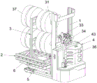
Fig. 1 is a schematic view of the overall structure of the present invention.
Fig. 2 is a schematic structural view of the forklift body of the invention.
Fig. 3 is a schematic partial cross-sectional structure of the present invention.
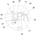
Fig. 4 is a partially enlarged structural view of a portion a in fig. 3.
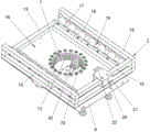
Fig. 5 is a schematic perspective view of the load-bearing underframe of the invention.
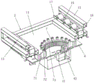
Figure 6 is a schematic view of a partial cross-sectional structure of the load-bearing chassis of the present invention.
Detailed Description
In order to facilitate understanding of those skilled in the art, the present invention will be further described with reference to the following examples and drawings, which are not intended to limit the present invention.
As shown in fig. 1 to 6, the automatic lifting truck provided by the present invention comprises a forklift body 1, a load-bearing chassis 2 rotatably mounted on the forklift body 1, and a load-carrying shelf 3 slidably mounted on the load-bearing chassis 2, wherein the forklift body 1 is mounted with a lifting driving assembly 33 and a control box assembly 4, the lifting driving assembly 33 is used for driving the load-bearing chassis 2 to perform a lifting motion along a vertical direction, and the control box assembly 4 is electrically connected to the lifting driving assembly 22.
In practical application, the lifting driving component 33 is a hydraulic cylinder; the lifting movement, the front-back movement and the rotation movement of the loading goods shelf 3 can be realized; when the goods on one side are unloaded, the bearing underframe 2 is rotated, so that the goods on the other side can be conveniently unloaded, the unloading operation can be finished without turning around in a narrow space; the full-automatic lifting action of the bearing underframe 2 can be controlled through the control box component 4, the operation is simple, and the labor force is saved.
In the embodiment, two lifting forks 5 are arranged on one side of the fork truck body 1, which is far away from the control box assembly 4, in a sliding manner along the vertical direction, a bearing plate 6 is fixedly arranged on each lifting fork 5, a rotating bearing assembly 7 is arranged on each bearing plate 6, each rotating bearing assembly 7 comprises an outer ring body 71 and an inner ring body 72, each outer ring body 71 is fixedly arranged on each bearing plate 6, the bearing underframe 2 and the inner ring body 72 are fixedly arranged, each inner ring body 72 is rotatably arranged inside each outer ring body 71, and the inner wall of each inner ring body 72 is provided with a plurality of engaging teeth 73; the control box assembly 4 comprises a driving member 41 mounted on the bearing plate 6, and an output end of the driving member 41 is provided with a driving gear part 42, and the driving gear part 42 is engaged with the teeth 73 of the inner ring body 72. The control box assembly 4 further comprises a central control system (not shown), a power supply (not shown) and a housing 43, wherein the driving member 41, the power supply and the lifting driving assembly 33 are electrically connected with the central control system, and the central control system and the power supply are arranged in the housing. Specifically, the power source may be a battery, and the driving member 41 may be a motor. The output end of the lifting driving component 33 is driven to automatically rise through the control box component 4, the lifting fork 5, the bearing plate 6, the bearing underframe 2 and the rotating bearing component 7 rise along with the control box component, the descending operation and the ascending operation are the same, the lifting operation is fully automatic, and the labor force is saved. The width of loading board 6 and the width parallel and level between two lift forks 5 prevent effectively that loading board 6 from interfering with external narrow and small storing space for this application can be in operation in narrow and small space.
In this embodiment, bearing chassis 2 includes chassis body 13 and two slide rail set spare 14, a plurality of side wall framves 15 are installed to chassis body 13, a plurality of side wall framves 15 enclose with chassis body 13 and establish and form spacing space 16, spacing space 16 is equipped with the export, two slide rail set spare 14 all include fixed channel spare 17 and a plurality of gyro wheel 18, two fixed channel spare 17 set up respectively in the both sides of spacing space 16, fixed channel spare 17 is equipped with recess 19, a plurality of gyro wheels 18 are all installed in recess 19, the outer peripheral face of gyro wheel 18 stretches out outside recess 19, load shelf 3 bears on a plurality of gyro wheels 18. Specifically, the loading shelf 3 is heavy and difficult to move, and the loading shelf 3 is supported on the rollers 18, so that the loading shelf 3 can be easily moved, and loading and unloading are facilitated.
In this embodiment, the load-bearing chassis 2 further includes a locking assembly, the locking assembly includes a locking fixing component 21 and a second locking component 22, the locking fixing component 21 includes a fastening mounting plate 23 and two jack plates 24 integrally bent and arranged on the fastening mounting plate 23, the fastening mounting plate 23 is mounted on the side wall frame 15, a locking space 25 is left between the two jack plates 24, one end of one jack plate 24, which is far away from the fastening mounting plate 23, is provided with a plurality of third locking through holes 26, one end of the other jack plate 24, which is far away from the fastening mounting plate 23, is provided with a plurality of fourth locking through holes 27, and the third locking through holes 26 and the fourth locking through holes 27 are correspondingly arranged; the second locking part 22 is provided with a hand-held ring 9 and a plurality of bolts 10, and the bolts 10 sequentially pass through the third locking through hole 26 and the fourth locking through hole 27; one end of the load-carrying shelf 3 is limited in the locking space 25, and the second locking part 22 is used for blocking the opening of the locking space 25. Specifically, the locking and fixing part 21 is substantially U-shaped and can be integrally stamped from sheet metal; after the bolt 10 of the second locking part 22 sequentially passes through the third locking through hole 26 and the fourth locking through hole 27, the opening of the locking space 25 is blocked, the load-bearing shelf 3 is locked, and the load-bearing chassis 2 is prevented from rotating in the process of moving and carrying goods, so that the goods are positioned, and the carrying efficiency is improved.
In this embodiment, the fastening mounting plate 23 is provided with a distance adjusting member 28, an output end of the distance adjusting member 28 abuts against the side frame 15, and the distance adjusting member 28 is used for adjusting a distance between the fastening mounting plate 23 and the side frame 15. Specifically, the distance adjusting part 28 can be selected from screws, bolts or telescopic parts, and the distance between the fastening mounting plate 23 and the side frame 15 can be adjusted according to the size of the load shelf 3, so that loosening can be prevented, the locking effect is good, and the stability and the reliability are improved.
In this embodiment, the loading shelf 3 includes a loading base 29, a supporting frame 30 and two cargo holders 31, the supporting frame 30 is disposed in the middle of the loading base 29, the two cargo holders 31 are disposed on two sides of the supporting frame 30, and the cargo holders 31 are used for placing the cargo 37. Specifically, both sides of the loading shelf 3 can be loaded with goods, so that more goods can be loaded, and the carrying efficiency is improved; goods mount 31 can select for use rod-shaped body, lamina or dictyosome etc. to be applicable to the goods of multiple difference and place, leave safe distance between goods and the goods, prevent to rub between the handling goods and lead to scraping flower, scratch goods.
In this embodiment, a plurality of stiffener supports 32 are provided between the cargo bed 29 and the support frame 30. Specifically, the support frame 30 can be firmer by the reinforcing rib support 32, so that the bearing strength is improved, and the stability and the reliability are improved.
In this embodiment, the forklift body 1 is provided with a control handle 36. Specifically, when the fork truck body 1 is pushed, the control can be carried out through the control handle 36, the operation is simple, and the labor force is saved.
The carrier consists of a fork truck body 1, a bearing underframe 2 and a loading goods shelf 3, adopts a storage battery as a power source, takes a motor as power and drives a vehicle to walk through gear transmission. The loading goods shelf 3 carried by the fork truck body 1 can realize three motion modes, which are respectively: lifting movement, back-and-forth movement, and rotational movement. The forklift body 1 adopts a hydraulic cylinder as lifting power, and the full-automatic lifting motion of the loading goods shelf 3 can be realized by manually operating the control handle 36 and the control box component 4. The fork truck body 1 is provided with a slide rail assembly 14, and the full-load loading shelf 3 can be easily pushed by a worker to slide on the slide rail assembly 14, so that the front and back movement of the loading shelf 3 is realized. The fork truck body 1 is provided with a rotating bearing assembly 7, and the load-carrying goods shelf 3 can be easily pushed to rotate on the rotating bearing assembly 7 by manpower.
The specific loading action mode is as follows:
(1) the forklift body 1 moves to a specified loading position, and the loading goods shelf 3 is manually pushed out from the slide rail assembly 14;
(2) the goods 37 are sequentially placed on the goods fixing frame 31, so that the goods fixing frame 31 is fully loaded, and the goods 37 are stable;
(3) the loaded load carrier 3 is manually pushed back to the spacing space 16 from the slide rail assembly 14, then the second locking part 22 is used to lock the load carrier 3 and the fork truck body 1 together, and then the fork truck is pushed away.
The specific unloading action mode is as follows:
(1) the forklift body 1 moves to a specified unloading position, the second locking part 22 is taken away, the loading goods shelf 3 is separated from the forklift body 1, and the loading goods shelf 3 is manually pushed out from the slide rail assembly 14;
(2) the plurality of cargos 37 are sequentially unloaded from the cargo holder 31, so that the cargo holder 31 is empty;
(3) and manually pulling back the unloaded load carrying rack 3 from the slide rail assembly 14, locking the load carrying rack 3 and the forklift body 1 together by the second locking member 22, and pushing away the forklift body 1.
This application need not the 1 turn round of fork truck body, facilitates the use, even if also can easily load and unload in narrow and small space. The design of the track assembly 14 allows for very easy loading of the racks onto the carts. The simple second locking member 22 is attached to lock the load carrier 3 and the forklift body 1 together quickly, thereby preventing the load carrier 3 from falling off during transportation. The forklift body 1 is provided with a brake mechanism (not shown in the figure) for preventing the forklift body 1 from moving during loading and unloading. Full automatic handling walking is realized to this application, and the goods rises and descends rotatory full automatization, reduces manual operation intensity.
All the technical features in the embodiment can be freely combined according to actual needs.
The above embodiments are preferred implementations of the present invention, and the present invention can be implemented in other ways without departing from the spirit of the present invention.
Claims (9)
1. The utility model provides an automatic formula lift carrier, includes the fork truck body, its characterized in that: still including rotate install in the bearing chassis and the slidable mounting of heap high car body in the load goods shelves of bearing chassis, heap high car body installs lift drive assembly and control box subassembly, lift drive assembly is used for ordering about the elevating movement is made along vertical direction to the bearing chassis, the control box subassembly with lift drive assembly electric connection.
2. The automated up-down cart according to claim 1, wherein: the forklift truck comprises a forklift truck body, a control box assembly, a bearing plate, a rotating bearing assembly, an outer ring body, an inner ring body and a plurality of engaging teeth, wherein the forklift truck body is provided with a lifting fork in a sliding manner along the vertical direction on one side away from the control box assembly, the lifting fork is fixedly provided with the bearing plate, the bearing plate is provided with the rotating bearing assembly, the rotating bearing assembly comprises the outer ring body and the inner ring body, the outer ring body is fixedly arranged on the bearing plate, the bearing underframe is fixedly arranged with the inner ring body, the inner ring body is rotatably arranged in the outer ring body, and the inner wall of the inner ring body is provided with the plurality of engaging teeth; the control box subassembly including install in the driving piece of loading board, the output of driving piece is provided with initiative gear part, initiative gear part with the rodent meshing of interior ring member.
3. The automated up-down cart according to claim 2, wherein: the control box assembly further comprises a central control system, a power supply and a shell, the driving piece, the power supply and the lifting driving assembly are electrically connected with the central control system, and the central control system and the power supply are arranged in the shell.
4. The automated up-down cart according to claim 1, wherein: the bearing chassis includes chassis body and two slide rail set spares, the chassis body is installed a plurality of side wall framves, and is a plurality of the side wall frame with the chassis body encloses to establish and forms spacing space, spacing space is equipped with the export, two slide rail set spare all includes fixed slot spare and a plurality of gyro wheel, two fixed slot spare set up respectively in the both sides in spacing space, fixed slot spare is equipped with the recess, and is a plurality of the gyro wheel all install in the recess, the outer peripheral face of gyro wheel stretches suddenly outside the recess, load goods shelves bear in a plurality of on the gyro wheel.
5. The automated up-down cart according to claim 4, wherein: the bearing underframe further comprises a locking assembly, the locking assembly comprises a locking fixing part and a second locking part, the locking fixing part comprises a fastening mounting plate and two jack plates which are integrally bent and arranged on the fastening mounting plate, the fastening mounting plate is arranged on one side wall frame, a locking space is reserved between the two jack plates, one end, away from the fastening mounting plate, of one jack plate is provided with a plurality of third locking through holes, one end, away from the fastening mounting plate, of the other jack plate is provided with a plurality of fourth locking through holes, and the third locking through holes and the fourth locking through holes are correspondingly arranged; the second locking component is provided with a handheld ring and a plurality of bolts, and the bolts sequentially penetrate through the third locking through hole and the fourth locking through hole; one end of the load-carrying goods shelf is limited in the locking space, and the second locking part is used for plugging the opening of the locking space.
6. The automated up-down cart according to claim 5, wherein: the fastening mounting panel is installed apart from the regulating part, apart from the output of regulating part with side wall frame butt, apart from the regulating part be used for adjusting the fastening mounting panel with distance between the side wall frame.
7. The automated up-down cart according to claim 1, wherein: the loading goods shelf comprises a goods carrying base, a supporting frame and two goods fixing frames, wherein the supporting frame is arranged in the middle of the goods carrying base, the two goods fixing frames are respectively arranged on two sides of the supporting frame, and the goods fixing frames are used for placing goods.
8. The automated up-down cart according to claim 7, wherein: a plurality of reinforcing rib supporting pieces are arranged between the cargo carrying base and the supporting frame.
9. The automated up-down cart according to claim 1, wherein: the control handle is installed to the fork truck body, control handle is equipped with the rudder, the rudder is used for controlling the steering of fork truck body turns to for the rudder handle formula.
Priority Applications (1)
| Application Number | Priority Date | Filing Date | Title |
|---|---|---|---|
| CN202110705293.3A CN113636498B (en) | 2021-06-24 | 2021-06-24 | Automatic lifting carrier |
Applications Claiming Priority (1)
| Application Number | Priority Date | Filing Date | Title |
|---|---|---|---|
| CN202110705293.3A CN113636498B (en) | 2021-06-24 | 2021-06-24 | Automatic lifting carrier |
Publications (2)
| Publication Number | Publication Date |
|---|---|
| CN113636498A true CN113636498A (en) | 2021-11-12 |
| CN113636498B CN113636498B (en) | 2023-05-23 |
Family
ID=78416224
Family Applications (1)
| Application Number | Title | Priority Date | Filing Date |
|---|---|---|---|
| CN202110705293.3A Active CN113636498B (en) | 2021-06-24 | 2021-06-24 | Automatic lifting carrier |
Country Status (1)
| Country | Link |
|---|---|
| CN (1) | CN113636498B (en) |
Citations (6)
| Publication number | Priority date | Publication date | Assignee | Title |
|---|---|---|---|---|
| CN202436643U (en) * | 2012-02-21 | 2012-09-19 | 山东博特精工股份有限公司 | Heavy-load storage rack |
| CN205035026U (en) * | 2015-08-28 | 2016-02-17 | 黄遵建 | Automatic pallet truck |
| CN105858543A (en) * | 2016-05-16 | 2016-08-17 | 武汉理工大学 | Four-way movable forklift based on rotatable workbench structure |
| CN210012293U (en) * | 2019-02-28 | 2020-02-04 | 浙江索控科技有限公司 | Industrial automation's work or material rest promotes slewer |
| CN112299307A (en) * | 2020-10-15 | 2021-02-02 | 苏州冠科工业设备有限公司 | Gooseneck type stacker |
| CN113003487A (en) * | 2021-04-08 | 2021-06-22 | 合肥搬易通科技发展有限公司 | Four-way stacking vehicle with storage area |
-
2021
- 2021-06-24 CN CN202110705293.3A patent/CN113636498B/en active Active
Patent Citations (6)
| Publication number | Priority date | Publication date | Assignee | Title |
|---|---|---|---|---|
| CN202436643U (en) * | 2012-02-21 | 2012-09-19 | 山东博特精工股份有限公司 | Heavy-load storage rack |
| CN205035026U (en) * | 2015-08-28 | 2016-02-17 | 黄遵建 | Automatic pallet truck |
| CN105858543A (en) * | 2016-05-16 | 2016-08-17 | 武汉理工大学 | Four-way movable forklift based on rotatable workbench structure |
| CN210012293U (en) * | 2019-02-28 | 2020-02-04 | 浙江索控科技有限公司 | Industrial automation's work or material rest promotes slewer |
| CN112299307A (en) * | 2020-10-15 | 2021-02-02 | 苏州冠科工业设备有限公司 | Gooseneck type stacker |
| CN113003487A (en) * | 2021-04-08 | 2021-06-22 | 合肥搬易通科技发展有限公司 | Four-way stacking vehicle with storage area |
Also Published As
| Publication number | Publication date |
|---|---|
| CN113636498B (en) | 2023-05-23 |
Similar Documents
| Publication | Publication Date | Title |
|---|---|---|
| CN205574010U (en) | Manual lift floor truck | |
| CN113860219B (en) | Vehicle-mounted cargo loading and unloading forklift and working method thereof | |
| EP0553086B1 (en) | Self elevating forklift truck | |
| CN113636498B (en) | Automatic lifting carrier | |
| CN113636502B (en) | Manual carrier | |
| CN114477028A (en) | Electric carrier with double-layer loading function | |
| CN208439261U (en) | A kind of Multifunction tow | |
| CN217708779U (en) | Special carrier for spraying inner wall of barrel and spraying system | |
| CN216836991U (en) | Lifting adjustable forklift | |
| CN111516764A (en) | Vertical self-jacking separable anti-explosion container and combustible and explosive dangerous goods transportation system | |
| CN213651242U (en) | Multifunctional unloading device for semitrailer | |
| CN216145729U (en) | Battery package transfer device | |
| CN216944673U (en) | Goods conveying device for three-dimensional warehouse | |
| CN214647903U (en) | Hydrogen storage bottle loading and unloading structure of hydrogen storage bottle transport truck | |
| CN215756214U (en) | Automatic loading and unloading device and transportation platform | |
| CN211032522U (en) | Automatic battery replacing device of electric forklift | |
| CN115716625A (en) | A auxiliary device that is used for new energy automobile battery to lift by crane dismouting | |
| CN215793375U (en) | Self-discharging formula removes carrier | |
| CN213505817U (en) | Semi-automatic carrying forklift | |
| CN209321001U (en) | A kind of cart | |
| CN112441434A (en) | Loading and unloading trolley and system | |
| CN220115032U (en) | Steel pallet convenient for loading and unloading goods | |
| CN215850714U (en) | Carrier loader | |
| CN220974236U (en) | Storage shallow that stability is good | |
| CN222476077U (en) | Special truck for loading and unloading box trucks |
Legal Events
| Date | Code | Title | Description |
|---|---|---|---|
| PB01 | Publication | ||
| PB01 | Publication | ||
| SE01 | Entry into force of request for substantive examination | ||
| SE01 | Entry into force of request for substantive examination | ||
| GR01 | Patent grant | ||
| GR01 | Patent grant |