CN113611231A - A guide device for park - Google Patents
A guide device for park Download PDFInfo
- Publication number
- CN113611231A CN113611231A CN202110929075.8A CN202110929075A CN113611231A CN 113611231 A CN113611231 A CN 113611231A CN 202110929075 A CN202110929075 A CN 202110929075A CN 113611231 A CN113611231 A CN 113611231A
- Authority
- CN
- China
- Prior art keywords
- motor
- base
- guide
- plate
- partition
- Prior art date
- Legal status (The legal status is an assumption and is not a legal conclusion. Google has not performed a legal analysis and makes no representation as to the accuracy of the status listed.)
- Pending
Links
- 230000007246 mechanism Effects 0.000 claims abstract description 58
- 238000005192 partition Methods 0.000 claims description 28
- 230000005389 magnetism Effects 0.000 claims 2
- 230000000694 effects Effects 0.000 description 4
- 230000008859 change Effects 0.000 description 3
- 230000009466 transformation Effects 0.000 description 3
- 230000009471 action Effects 0.000 description 2
- 230000003028 elevating effect Effects 0.000 description 2
- 238000000034 method Methods 0.000 description 2
- 230000008569 process Effects 0.000 description 2
- 238000007792 addition Methods 0.000 description 1
- 230000009286 beneficial effect Effects 0.000 description 1
- 230000007547 defect Effects 0.000 description 1
- 238000010586 diagram Methods 0.000 description 1
- 238000004146 energy storage Methods 0.000 description 1
- 230000013011 mating Effects 0.000 description 1
- 230000004048 modification Effects 0.000 description 1
- 238000012986 modification Methods 0.000 description 1
- 238000006467 substitution reaction Methods 0.000 description 1
- 230000000007 visual effect Effects 0.000 description 1
Images


Classifications
-
- G—PHYSICS
- G09—EDUCATION; CRYPTOGRAPHY; DISPLAY; ADVERTISING; SEALS
- G09F—DISPLAYING; ADVERTISING; SIGNS; LABELS OR NAME-PLATES; SEALS
- G09F15/00—Boards, hoardings, pillars, or like structures for notices, placards, posters, or the like
-
- F—MECHANICAL ENGINEERING; LIGHTING; HEATING; WEAPONS; BLASTING
- F21—LIGHTING
- F21S—NON-PORTABLE LIGHTING DEVICES; SYSTEMS THEREOF; VEHICLE LIGHTING DEVICES SPECIALLY ADAPTED FOR VEHICLE EXTERIORS
- F21S9/00—Lighting devices with a built-in power supply; Systems employing lighting devices with a built-in power supply
- F21S9/02—Lighting devices with a built-in power supply; Systems employing lighting devices with a built-in power supply the power supply being a battery or accumulator
- F21S9/03—Lighting devices with a built-in power supply; Systems employing lighting devices with a built-in power supply the power supply being a battery or accumulator rechargeable by exposure to light
- F21S9/035—Lighting devices with a built-in power supply; Systems employing lighting devices with a built-in power supply the power supply being a battery or accumulator rechargeable by exposure to light the solar unit being integrated within the support for the lighting unit, e.g. within or on a pole
-
- F—MECHANICAL ENGINEERING; LIGHTING; HEATING; WEAPONS; BLASTING
- F21—LIGHTING
- F21V—FUNCTIONAL FEATURES OR DETAILS OF LIGHTING DEVICES OR SYSTEMS THEREOF; STRUCTURAL COMBINATIONS OF LIGHTING DEVICES WITH OTHER ARTICLES, NOT OTHERWISE PROVIDED FOR
- F21V23/00—Arrangement of electric circuit elements in or on lighting devices
- F21V23/04—Arrangement of electric circuit elements in or on lighting devices the elements being switches
- F21V23/0442—Arrangement of electric circuit elements in or on lighting devices the elements being switches activated by means of a sensor, e.g. motion or photodetectors
- F21V23/0464—Arrangement of electric circuit elements in or on lighting devices the elements being switches activated by means of a sensor, e.g. motion or photodetectors the sensor sensing the level of ambient illumination, e.g. dawn or dusk sensors
-
- G—PHYSICS
- G09—EDUCATION; CRYPTOGRAPHY; DISPLAY; ADVERTISING; SEALS
- G09F—DISPLAYING; ADVERTISING; SIGNS; LABELS OR NAME-PLATES; SEALS
- G09F13/00—Illuminated signs; Luminous advertising
- G09F13/04—Signs, boards or panels, illuminated from behind the insignia
-
- G—PHYSICS
- G09—EDUCATION; CRYPTOGRAPHY; DISPLAY; ADVERTISING; SEALS
- G09F—DISPLAYING; ADVERTISING; SIGNS; LABELS OR NAME-PLATES; SEALS
- G09F15/00—Boards, hoardings, pillars, or like structures for notices, placards, posters, or the like
- G09F2015/0093—Tensioned structures
Abstract
The invention discloses a guide device for a park, which comprises a base and an upright post, wherein the upright post is arranged above the base, walking wheels are arranged at the bottom of the base, and a guide mechanism is arranged at the top of the upright post. According to the invention, the travelling wheels are convenient for the whole device to move, the guide scroll of the guide mechanism can be replaced, and different guide scrolls can be replaced according to different scenic spots or projects, so that the working efficiency is improved, the actual use requirement can be met, the device can be reused, and the use cost is reduced.
Description
Technical Field
The invention belongs to the technical field of guide equipment, and particularly relates to a guide device for a park.
Background
The park is a public green land for public to visit, watch, rest, develop scientific culture, exercise body and other activities, has perfect facilities and good greening environment, and the park guide device is the most important tour guide in the park, guides travelers to visit the route and obtains the geographic coordinates of various service places, and is a guide direction plate, such as a guide sign plate of each occasion in the park.
In order to realize the diversification of function, the park can increase the sight spot or hold the activity temporarily sometimes, because current guide device generally fixes in ground, and mostly be disposable, increase or hold the activity when new sight spot, guide device can't in time make the change according to actual conditions, the flexibility is relatively poor, reinstallation then can consume a large amount of manpower, material resources, and the time spent when changing is longer, speed is slower, inefficiency, the normal use that influences guide device even still, can't satisfy the demand of in-service use.
Disclosure of Invention
The invention aims to overcome the defects in the prior art, and provides a guide device for a park, which is convenient for the whole device to move through a travelling wheel, a guide scroll of a guide mechanism can be replaced, and different guide scrolls can be replaced according to different scenic spots or projects, so that the working efficiency is improved, the actual use requirements can be met, the device can be reused, and the use cost is reduced.
In order to achieve the purpose, the invention adopts the technical scheme that:
the utility model provides a guide device for park, includes base, stand, column mouting is in the top of base, the walking wheel is installed to the base bottom, is convenient for whole device through the walking wheel and carries out the removal of position, guide mechanism is installed at the top of stand, and guide mechanism's guide spool can be changed, changes different guide spools according to different sight spots or project to improve the efficiency of work, can satisfy the demand of in-service use, the device can used repeatedly, has reduced use cost.
Preferably, the guide mechanism comprises a box body, a first motor, a guide scroll, a support plate and a baffle plate, the box body is arranged on a stand column, a first baffle is arranged in the box body, the first motor is arranged between one side of the first baffle and the box body, the guide scroll is arranged between the other side of the first baffle and the box body, a guide view is wound on the guide scroll, a support shaft is rotatably arranged on one side of the box body, which is far away from the first baffle, the end part of an output shaft of the first motor penetrates through the first baffle and is connected with the guide scroll through a locking bolt, the end part of the support shaft is connected with the guide scroll through a locking bolt, the baffle plate is arranged below the guide scroll and on the box body in a sliding manner, a through groove is formed in the baffle plate, the guide view of the guide scroll can penetrate through the through groove to move downwards, the support plate is arranged on one side of the through groove in the baffle plate, and is used for bearing the guide view, the bottom of the baffle is provided with a magnetic attraction seat, a magnet is absorbed in the magnetic attraction seat, the magnet is provided with a connecting groove, by installing the connecting groove on the magnet at the end part of the guiding view and then connecting the magnet and the magnetic suction seat in an attracting way, thereby realizing the fixation of the guide picture, the first motor works to drive the guide scroll to rotate, the guide picture passes through the through groove to move downwards, when the guide view is completely unfolded, the guide view is fixed by installing the magnet, when different guide view is required to be replaced, the bottom of the box body is opened through the sliding baffle, the prior guide scroll is taken down from the first motor and the supporting shaft, the new guide scroll is arranged on the first motor and the supporting shaft and is fixed through the locking bolt, then, the baffle is pushed to the initial position, the guide view is replaced, the replacement process is simple and quick, and the working efficiency is improved.
Preferably, a second partition plate is arranged inside the base, a telescopic mechanism is arranged between the lower part of the second partition plate and the base, the bottom of the telescopic mechanism is connected with a walking wheel, the telescopic mechanism comprises a fourth motor, a second worm, a swinging rod, a loop bar and a slide bar, the fourth motor is arranged on the second partition plate through a connecting plate, the second worm is arranged at the end part of an output shaft of the fourth motor, bearing plates are arranged on two sides of the bottom of the fourth motor, two bearing plates on the same side are provided with connecting rods in a rotating manner, the swinging rod is arranged at two ends of the connecting rods, a third gear is arranged on the connecting rods and between the two bearing plates, the third gear is meshed with the second worm and can drive the third gear to rotate when the second worm rotates, the loop bar is arranged between the base and the second partition plate, and the slide bar is arranged in the loop bar in a sliding manner, the cooperation post is installed on the slide bar top, the slide bar bottom is passed the base and is connected with the walking wheel, the spout has all been seted up on the loop bar lateral wall, the tip of swinging arms passes spout and sliding bar connection, the one end that the swinging arms is close to the slide bar is seted up flutedly, and the cooperation post on the slide bar is installed in the recess on the swinging arms, the standing groove with walking wheel one-to-one is seted up to the bottom of base, and when whole device need not remove, fourth motor work drives the second worm and rotates, and third gear and second worm meshing drive the connecting rod and rotate on the loading board, and the swinging arms rotates along with the connecting rod and drives the slide bar to base internal motion, because walking wheel and sliding bar connection make walking wheel upward movement to the standing groove in, base and ground contact this moment have increased the stability of during operation.
Preferably, rotary mechanism is installed to the top of second baffle, the top of base, column mouting is in rotary mechanism's top, rotary mechanism includes third motor, pivot, the third motor is installed at the base top, third motor output shaft tip extends to the inside of base and installs first gear, the pivot is installed on the second baffle, the one end that the second baffle was kept away from in the pivot extends to the base outside and installs and place the board, install the second gear in the pivot, the second gear is connected with first gear engagement, and it is rotatory to drive first gear through third motor work, and the second gear drives the pivot with first gear engagement and rotates on the base, places the board and rotates thereupon to can drive the rotation of guide mechanism, the adjustment of the angle of the guide mechanism of being convenient for.
Preferably, the internally mounted of stand has elevating system, elevating system includes second motor, first worm, bracing piece, rack, conducting bar, the second motor is installed on the stand inner wall, the output shaft tip at the second motor is installed to first worm, one side at the second motor is installed to the bracing piece, it installs the top at the bracing piece to guide the mechanism, the rack is installed on the bracing piece and is connected with first worm meshing, the conducting bar is installed on the bracing piece and is connected with the stand cooperation, the quantity of conducting bar is a plurality of, has improved the stability of bracing piece up-and-down motion, drives first worm through second motor work and rotates the rack toothing on with the bracing piece to make the bracing piece along stand up-and-down motion under the effect of conducting bar, drive and guide the mechanism height-adjusting from top to bottom, the use of the device of being convenient for.
Preferably, branch is installed at guide mechanism top both ends, the photovoltaic board system is installed at the top of branch, the internally mounted of box has the battery, battery and photovoltaic board system electric connection can be with solar energy transformation to the electric energy storage battery through the photovoltaic board system, supply power for whole device through the battery, need not external power supply, have improved the convenience that the device used.
Preferably, the backup pad is the luminescent plate, install the light sense ware on the luminescent plate, light sense ware and luminescent plate electric connection, when the light sense ware senses external light when darker, the luminescent plate work is lighted and is led the view, and people's of being convenient for look over has increased the function of device.
The invention has the beneficial effects that:
1) the whole device of being convenient for through the walking wheel carries out the removal of position, and the guide spool of guide mechanism can be changed, changes different guide spools according to sight spot or project of difference to improve the efficiency of work, can satisfy the demand of in-service use, the device can used repeatedly, has reduced use cost.
2) The fourth motor works to drive the second worm to rotate, the third gear is meshed with the second worm to drive the connecting rod to rotate on the bearing plate, the swinging rod rotates along with the connecting rod to drive the sliding rod to move towards the inside of the base, and the walking wheel is connected with the sliding rod to enable the walking wheel to move upwards to the placing groove, so that the base is in contact with the ground, and the stability in working is improved.
3) The first gear is driven to rotate through the work of the third motor, the second gear is meshed with the first gear to drive the rotating shaft to rotate on the base, and the supporting plate rotates along with the rotating shaft, so that the guide mechanism can be driven to rotate, and the angle of the guide mechanism can be adjusted conveniently.
4) The first worm is driven to rotate to be meshed with the rack on the supporting rod through the work of the second motor, so that the supporting rod moves up and down along the stand column under the action of the guide strip to drive the guide mechanism to adjust the height up and down, and the device is convenient to use.
5) Branch is installed at guide mechanism top both ends, and the photovoltaic board system is installed at the top of branch, the internally mounted of box has the battery, battery and photovoltaic board system electric connection, can store the battery with solar energy transformation to the electric energy through the photovoltaic board system, supplies power for whole device through the battery, need not external power supply, has improved the convenience that the device used.
6) The backup pad is the luminescent plate, installs the light sense ware on the luminescent plate, light sense ware and luminescent plate electric connection, and when light sense ware sensed external light when darker, the luminescent plate work was lighted and is led the view, and the people of being convenient for look over has increased the function of device.
Drawings
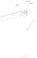
FIG. 1 is a schematic view of a guiding device for a park according to the present invention.
FIG. 2 is a schematic view of the internal structure of a base in a guiding device for a park according to the present invention.
FIG. 3 is a schematic view showing a configuration of a retracting mechanism of a guide for a park according to the present invention.
FIG. 4 is a schematic view of the connection between the swing rod and the sliding rod of the guiding device for park according to the present invention.
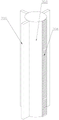
FIG. 5 is a schematic structural diagram of a lifting mechanism and a guiding mechanism in a guiding device for a park according to the present invention.
FIG. 6 is a schematic view of a support rod structure of a guiding device for a park according to the present invention.
FIG. 7 is a schematic view of a light-emitting plate structure of a guiding device for a park according to the present invention.
Fig. 8 is an enlarged view of a portion a of fig. 7.
In the figure: 1. a base; 2. a traveling wheel; 3. a column; 4. a guide mechanism; 401. a box body; 402. a first separator; 403. a first motor; 404. a storage battery; 405. a guide reel; 406. a support shaft; 407. locking the bolt; 408. a support plate; 409. a magnetic attraction seat; 410. a baffle plate; 411. a through groove; 412. a magnet; 413. connecting grooves; 414. a light sensor; 5. a strut; 6. a photovoltaic panel system; 7. a lifting mechanism; 701. a second motor; 702. a first worm; 703. a support bar; 704. a rack; 705. conducting bars; 8. a rotation mechanism; 801. a third motor; 802. a first gear; 803. a rotating shaft; 804. a second gear; 805. placing the plate; 9. a telescoping mechanism; 901. a fourth motor; 902. a second worm; 903. a third gear; 904. a connecting rod; 905. a swing lever; 9051. a groove; 906. a loop bar; 9061. a chute; 907. a slide bar; 9071. a mating post; 908. a carrier plate; 10. a second separator; 11. a placement groove; 12. a connecting plate.
Detailed Description
The technical solutions in the embodiments of the present invention are clearly and completely described below with reference to fig. 1 to 8, and it is obvious that the described embodiments are only a part of the embodiments of the present invention, and not all embodiments. All other embodiments, which can be derived by a person skilled in the art from the embodiments given herein without making any creative effort, shall fall within the protection scope of the present invention.
In the description of the present invention, it is to be understood that the terms "longitudinal", "lateral", "upper", "lower", "front", "rear", "left", "right", "vertical", "horizontal", "top", "bottom", "inner", "outer", and the like, indicate orientations or positional relationships based on those shown in the drawings, are merely for convenience of description of the present invention, and do not indicate or imply that the referenced devices or elements must have a particular orientation, be constructed and operated in a particular orientation, and thus, are not to be construed as limiting the present invention.
The utility model provides a guide's device for park, includes base 1, stand 3, the top at base 1 is installed to stand 3, walking wheel 2 is installed to base 1 bottom, and the whole device of being convenient for through walking wheel 2 carries out the removal of position, guide mechanism 4 is installed at the top of stand 3, and guide mechanism 4's guide spool 405 can be changed, changes different guide spools according to different sight spots or projects to improve the efficiency of work, can satisfy the demand of in-service use, the device can used repeatedly, has reduced use cost.
The guide mechanism 4 comprises a box body 401, a first motor 403, a guide scroll 405, a support plate 408 and a baffle plate 410, wherein the box body 401 is installed on the upright post 3, a first partition 402 is installed inside the box body 401, the first motor 403 is installed between one side of the first partition 402 and the box body 401, the guide scroll 405 is arranged between the other side of the first partition 402 and the box body 401, a guide view is wound on the guide scroll 405, a support shaft 406 is rotatably installed at one side of the box body 401 far away from the first partition 402, the end part of an output shaft of the first motor 403 passes through the first partition 402 and is connected with the guide scroll 405 through a locking bolt 407, the end part of the support shaft 406 is connected with the guide scroll 405 through a locking bolt 407, a baffle plate 410 is slidably installed below the guide scroll 405 and on the box body 401, a through groove 411 is formed in the baffle plate 410, and a guide view of the guide scroll 405 can pass through the through groove 411 to move downwards, a support plate 408 is installed on one side of the through groove 411 of the baffle plate 410, the support plate 408 is used for bearing a guide view, a magnetic attraction seat 409 is installed at the bottom of the baffle plate 410, a magnet 412 is attracted in the magnetic attraction seat 409, a connecting groove 413 is formed in the magnet 412, the connecting groove 413 in the magnet 412 is installed at the end of the guide view, then the magnet 412 and the magnetic attraction seat 409 are attracted and connected, so that the guide view is fixed, the guide scroll 405 is driven to rotate by the operation of the first motor 403, the guide view passes through the through groove 411 to move downwards, when the guide view is completely unfolded, the guide view is fixed by installing the magnet 412, when different guide views need to be changed, the bottom of the box body 401 is opened by the sliding baffle plate 410, the previous guide scroll 405 is taken down from the first motor 403 and the support shaft 406, a new guide scroll 405 is installed on the first motor 403 and the support shaft 406 and is fixed by the locking bolt 407, then promote baffle 410 to initial position, accomplish the change of leading the view, the change process is simple quick, has improved the efficiency of work, the backup pad 408 is the luminescent plate, install light sense ware 414 on the luminescent plate, light sense ware 414 and luminescent plate electric connection, when light sense ware 414 senses external light when darker, the light sense ware work illuminates leading the view, and the people of being convenient for look over has increased the function of device.
A second partition plate 10 is installed inside the base 1, a telescopic mechanism 9 is installed between the lower portion of the second partition plate 10 and the base 1, the bottom of the telescopic mechanism 9 is connected with the traveling wheel 2, the telescopic mechanism 9 comprises a fourth motor 901, a second worm 902, a swinging rod 905, a loop bar 906 and a sliding rod 907, the fourth motor 901 is installed on the second partition plate 10 through a connecting plate 12, the second worm 902 is installed at the end portion of an output shaft of the fourth motor 901, bearing plates 908 are installed on two sides of the bottom of the fourth motor 901, the number of the bearing plates 908 on the same side is two and a connecting rod 904 is installed in a rotating manner, the swinging rod 905 is installed at two ends of the connecting rod 904, a third gear 903 is installed on the connecting rod 904 and between the two bearing plates 908, the third gear 903 is meshed with the second worm 902 and can drive the third gear 903 to rotate when the second worm rotates, the sleeve rod 906 is installed between the base 1 and the second partition plate 10, the sliding rod 907 is installed in the sleeve rod 906 in a sliding mode, the top end of the sliding rod 907 is provided with a matching column 9071, the bottom end of the sliding rod 907 penetrates through the base 1 to be connected with the traveling wheel 2, the side wall of the sleeve rod 906 is provided with sliding grooves 9061, the end portion of the swinging rod 905 penetrates through the sliding grooves 9061 to be connected with the sliding rod 907, one end, close to the sliding rod 907, of the swinging rod 905 is provided with a groove 9051, the matching column 9071 on the sliding rod 907 is installed in the groove 9051 on the swinging rod 905, the bottom of the base 1 is provided with placing grooves 11 corresponding to the traveling wheels 2 one by one, when the whole device does not need to move, the fourth motor 901 works to drive the second worm 902 to rotate, the third gear 903 is meshed with the second worm 902 to drive the connecting rod 904 to rotate on the bearing plate 908, the swinging rod 905 rotates along with the connecting rod 904 to drive the sliding rod 907 to move towards the inside of the base 1, the walking wheels 2 are connected with the sliding rod 907, so that the walking wheels 2 move upwards into the placing groove 11, and at the moment, the base 1 is in contact with the ground, and the stability in working is improved.
A rotating mechanism 8 is arranged above the second partition plate 10 and at the top of the base 1, the upright column 3 is arranged above the rotating mechanism 8, the rotating mechanism 8 comprises a third motor 801 and a rotating shaft 803, the third motor 801 is arranged at the top of the base 1, the end part of an output shaft of the third motor 801 extends into the base 1 and is provided with a first gear 802, the rotating shaft 803 is arranged on the second partition plate 10, one end of the rotating shaft 803, far away from the second partition plate 10, extends to the outside of the base 1 and is provided with a placing plate 805, the rotating shaft 803 is provided with a second gear 804, the second gear 804 is meshed with the first gear 802, the third motor 801 is used for driving the first gear 802 to rotate, the second gear 804 is meshed with the first gear 802 to drive the rotating shaft 803 to rotate on the base 1, the placing plate 805 rotates along with the rotating shaft, and thus the visual guide mechanism 4 can be driven to rotate, facilitating the adjustment of the angle of the vision guide mechanism 4.
The lifting mechanism 7 is installed inside the upright post 3, the lifting mechanism 7 comprises a second motor 701, a first worm 702, a support rod 703, a rack 704 and guide bars 705, the second motor 701 is installed on the inner wall of the upright post 3, the first worm 702 is installed at the end part of the output shaft of the second motor 701, the support rod 703 is installed at one side of the second motor 701, the guide mechanism 4 is installed at the top end of the support rod 703, the rack 704 is installed on the support rod 703 and is meshed with the first worm 702, the guide bars 705 are installed on the support rod 703 and are matched and connected with the upright post 3, the number of the guide bars 705 is multiple, the stability of the vertical movement of the support rod 703 is improved, the second motor 701 drives the first worm 702 to rotate and be meshed with the rack 704 on the support rod 703, so that the support rod 703 moves up and down along the upright post 3 under the action of the guide bars 705, the height of the guide mechanism 4 is adjusted up and down, which is convenient for the use of the device.
Branch 5 is installed at 4 top both ends of guide mechanism, photovoltaic board system 6 is installed at the top of branch 5, the internally mounted of box 401 has battery 404, battery 404 and the 6 electric connection of photovoltaic board system can store the battery 404 with solar energy transformation for the electric energy through photovoltaic board system 6, supply power for whole device through battery 404, need not external power supply, have improved the convenience that the device used.
The foregoing is merely exemplary and illustrative of the present invention and various modifications, additions and substitutions may be made by those skilled in the art to the specific embodiments described without departing from the scope of the present invention as defined in the accompanying claims.
Claims (8)
1. The utility model provides a guide device for park, includes base, stand, the column mouting is in the top of base, its characterized in that, the walking wheel is installed to the base bottom, guide mechanism is installed at the top of stand.
2. The guiding device for the park as claimed in claim 1, wherein the guiding mechanism comprises a box, a first motor, a guiding scroll, a supporting plate, and a baffle plate, the box is mounted on the column, a first partition is mounted inside the box, the first motor is mounted between one side of the first partition and the box, the guiding scroll is disposed between the other side of the first partition and the box, the guiding scroll is wound with the guiding view, a supporting shaft is rotatably mounted on one side of the box away from the first partition, the end of the output shaft of the first motor passes through the first partition and is connected with the guiding scroll through a locking bolt, the end of the supporting shaft is connected with the guiding scroll through a locking bolt, a baffle plate is slidably mounted on the box below the guiding scroll, a through slot is formed on the baffle plate, the supporting plate is mounted on one side of the through slot on the baffle plate, the bottom of baffle is installed the magnetism and is inhaled the seat, adsorb magnet in the magnetism inhale the seat, set up the spread groove on the magnet.
3. The park guiding device as recited in claim 1, wherein a second partition plate is installed inside the base, a telescopic mechanism is installed below the second partition plate and between the base and the bottom of the telescopic mechanism, the bottom of the telescopic mechanism is connected with the traveling wheels, the telescopic mechanism comprises a fourth motor, a second worm, a swinging rod, a loop bar and a sliding rod, the fourth motor is installed on the second partition plate through a connecting plate, the second worm is installed at the end of an output shaft of the fourth motor, bearing plates are installed at two sides of the bottom of the fourth motor, two bearing plates on the same side are provided with connecting rods in a rotating manner, the swinging rod is installed at two ends of the connecting rod, a third gear is installed on the connecting rod and between the two bearing plates, the third gear is in meshing connection with the second worm, the loop bar is installed between the base and the second partition plate, and the sliding rod is installed in the loop bar in a sliding manner, the utility model discloses a slide bar, including slide bar, loop bar lateral wall, swinging arms, base, walking wheel, swinging arms, the cooperation post is installed on the slide bar top, the slide bar bottom is passed the base and is connected with the walking wheel, all seted up the spout on the loop bar lateral wall, the tip of swinging arms passes spout and slide bar connection, the one end that the swinging arms is close to the slide bar is seted up flutedly, and the cooperation post on the slide bar is installed in the recess on the swinging arms, the standing groove with walking wheel one-to-one is seted up to the bottom of base.
4. The guiding device for the park as recited in claim 3, wherein a rotating mechanism is mounted above the second partition and on the top of the base, the column is mounted above the rotating mechanism, the rotating mechanism comprises a third motor and a rotating shaft, the third motor is mounted on the top of the base, an end of an output shaft of the third motor extends to the inside of the base and is provided with a first gear, the rotating shaft is mounted on the second partition, an end of the rotating shaft, which is far away from the second partition, extends to the outside of the base and is provided with a placing plate, and the rotating shaft is provided with a second gear, which is meshed with the first gear.
5. The guiding device for the park as recited in claim 1, wherein the vertical column is internally provided with a lifting mechanism, the lifting mechanism comprises a second motor, a first worm, a support rod, a rack and a guide bar, the second motor is mounted on the inner wall of the vertical column, the first worm is mounted at the end of the output shaft of the second motor, the support rod is mounted at one side of the second motor, the guiding mechanism is mounted at the top end of the support rod, the rack is mounted on the support rod and is engaged with the first worm, and the guide bar is mounted on the support rod and is engaged with the vertical column.
6. A guide device for use in a park as claimed in claim 5, wherein the number of the guide strips is plural.
7. The guiding device for the park as recited in claim 2, wherein two ends of the top of the guiding mechanism are provided with a support rod, the top of the support rod is provided with a photovoltaic panel system, the inside of the box body is provided with a storage battery, and the storage battery is electrically connected with the photovoltaic panel system.
8. The guiding device as claimed in claim 2, wherein the supporting plate is a light-emitting plate, and the light-emitting plate is mounted with a light sensor electrically connected to the light-emitting plate.
Priority Applications (1)
| Application Number | Priority Date | Filing Date | Title |
|---|---|---|---|
| CN202110929075.8A CN113611231A (en) | 2021-08-13 | 2021-08-13 | A guide device for park |
Applications Claiming Priority (1)
| Application Number | Priority Date | Filing Date | Title |
|---|---|---|---|
| CN202110929075.8A CN113611231A (en) | 2021-08-13 | 2021-08-13 | A guide device for park |
Publications (1)
| Publication Number | Publication Date |
|---|---|
| CN113611231A true CN113611231A (en) | 2021-11-05 |
Family
ID=78340626
Family Applications (1)
| Application Number | Title | Priority Date | Filing Date |
|---|---|---|---|
| CN202110929075.8A Pending CN113611231A (en) | 2021-08-13 | 2021-08-13 | A guide device for park |
Country Status (1)
| Country | Link |
|---|---|
| CN (1) | CN113611231A (en) |
Citations (12)
| Publication number | Priority date | Publication date | Assignee | Title |
|---|---|---|---|---|
| CN2929880Y (en) * | 2006-08-01 | 2007-08-01 | 沈阳经纬数码科技有限公司 | Multiple picture automatic changing device |
| ES2337430A1 (en) * | 2007-04-30 | 2010-04-23 | Moidecar, S.L. | Expositor of sliding panels. (Machine-translation by Google Translate, not legally binding) |
| CN206975942U (en) * | 2017-05-05 | 2018-02-06 | 孙浩然 | A kind of moveable road safety marker board |
| CN108916554A (en) * | 2018-07-02 | 2018-11-30 | 安徽泾县宏图信息科技有限公司 | A kind of height-adjustable information service activities presentation device |
| CN109566034A (en) * | 2018-11-01 | 2019-04-05 | 南京后马种植专业合作社 | A kind of height-adjustable fruit flusher |
| CN209625645U (en) * | 2019-03-14 | 2019-11-12 | 陈静 | A kind of municipal gardens direction board of adjustable-angle |
| CN210398327U (en) * | 2019-09-17 | 2020-04-24 | 魏梅凤 | Rotating base for intelligent security equipment |
| CN210925106U (en) * | 2019-12-23 | 2020-07-03 | 湖南化工职业技术学院 | English teaching board |
| CN211624635U (en) * | 2019-12-12 | 2020-10-02 | 苏州澜普智能技术有限公司 | Wisdom garden is with direction billboard |
| CN112502762A (en) * | 2020-12-03 | 2021-03-16 | 苏州纳洲信息科技有限公司 | Supporting device for coal mining and using method thereof |
| CN212986642U (en) * | 2020-06-16 | 2021-04-16 | 吉林省通用科技信息咨询有限公司 | Information display of science and technology incubation garden based on thing networking |
| CN213121811U (en) * | 2020-08-21 | 2021-05-04 | 贵州轩通大数据科技有限责任公司 | Gas station oil gas concentration data monitoring device |
-
2021
- 2021-08-13 CN CN202110929075.8A patent/CN113611231A/en active Pending
Patent Citations (12)
| Publication number | Priority date | Publication date | Assignee | Title |
|---|---|---|---|---|
| CN2929880Y (en) * | 2006-08-01 | 2007-08-01 | 沈阳经纬数码科技有限公司 | Multiple picture automatic changing device |
| ES2337430A1 (en) * | 2007-04-30 | 2010-04-23 | Moidecar, S.L. | Expositor of sliding panels. (Machine-translation by Google Translate, not legally binding) |
| CN206975942U (en) * | 2017-05-05 | 2018-02-06 | 孙浩然 | A kind of moveable road safety marker board |
| CN108916554A (en) * | 2018-07-02 | 2018-11-30 | 安徽泾县宏图信息科技有限公司 | A kind of height-adjustable information service activities presentation device |
| CN109566034A (en) * | 2018-11-01 | 2019-04-05 | 南京后马种植专业合作社 | A kind of height-adjustable fruit flusher |
| CN209625645U (en) * | 2019-03-14 | 2019-11-12 | 陈静 | A kind of municipal gardens direction board of adjustable-angle |
| CN210398327U (en) * | 2019-09-17 | 2020-04-24 | 魏梅凤 | Rotating base for intelligent security equipment |
| CN211624635U (en) * | 2019-12-12 | 2020-10-02 | 苏州澜普智能技术有限公司 | Wisdom garden is with direction billboard |
| CN210925106U (en) * | 2019-12-23 | 2020-07-03 | 湖南化工职业技术学院 | English teaching board |
| CN212986642U (en) * | 2020-06-16 | 2021-04-16 | 吉林省通用科技信息咨询有限公司 | Information display of science and technology incubation garden based on thing networking |
| CN213121811U (en) * | 2020-08-21 | 2021-05-04 | 贵州轩通大数据科技有限责任公司 | Gas station oil gas concentration data monitoring device |
| CN112502762A (en) * | 2020-12-03 | 2021-03-16 | 苏州纳洲信息科技有限公司 | Supporting device for coal mining and using method thereof |
Similar Documents
| Publication | Publication Date | Title |
|---|---|---|
| CN110259211A (en) | A kind of intensive solar energy parking kiosk for electric vehicle | |
| CN111392186A (en) | Unmanned aerial vehicle storage device with photovoltaic charging function and capable of serving as take-off platform | |
| CN113611231A (en) | A guide device for park | |
| CN212081084U (en) | Solar street lamp with automatic cleaning function | |
| CN207279187U (en) | A kind of tourism guiding device with lifting regulating mechanism | |
| CN214249423U (en) | Lighting system for municipal construction | |
| CN212740589U (en) | Coal mine electromechanical lifting and transporting device | |
| CN213923948U (en) | Outer support bracket of high-altitude operation hanging basket | |
| CN114162025A (en) | Mobile power source car's modularization cabinet structure that charges | |
| CN112947596A (en) | New-energy outdoor water environment monitoring and processing device | |
| CN207121307U (en) | A kind of electric power field construction cable retractable cable system | |
| CN220380055U (en) | Solar refrigerator with storable idler wheels | |
| CN218438549U (en) | Parking area management direction indicating device | |
| CN218273551U (en) | Outdoor express cabinet convenient to remove | |
| CN114811488B (en) | Liftable street lamp | |
| CN213209123U (en) | Dust environmental protection detects monitor convenient to it is clean | |
| CN220320706U (en) | Energy-saving environmental gas monitoring equipment | |
| CN216158953U (en) | Energy-concerving and environment-protective type light is used in municipal administration | |
| CN217597048U (en) | Electronic equipment maintenance workbench capable of preventing parts from being lost | |
| CN211373667U (en) | Outdoor environment detection device | |
| CN215450328U (en) | Modular miniature library of intelligence | |
| CN220724934U (en) | Guardrail convenient to remove | |
| CN220623755U (en) | Solar lighting device for saline-alkali soil | |
| CN216259031U (en) | Integrated manager of competition equipment | |
| CN213047288U (en) | Physiotherapy workstation |
Legal Events
| Date | Code | Title | Description |
|---|---|---|---|
| PB01 | Publication | ||
| PB01 | Publication | ||
| SE01 | Entry into force of request for substantive examination | ||
| SE01 | Entry into force of request for substantive examination | ||
| RJ01 | Rejection of invention patent application after publication |
Application publication date: 20211105 |