CN113574285A - Sliding bearing - Google Patents
Sliding bearing Download PDFInfo
- Publication number
- CN113574285A CN113574285A CN202080018031.3A CN202080018031A CN113574285A CN 113574285 A CN113574285 A CN 113574285A CN 202080018031 A CN202080018031 A CN 202080018031A CN 113574285 A CN113574285 A CN 113574285A
- Authority
- CN
- China
- Prior art keywords
- bearing
- ring element
- plain bearing
- inner ring
- sliding bearing
- Prior art date
- Legal status (The legal status is an assumption and is not a legal conclusion. Google has not performed a legal analysis and makes no representation as to the accuracy of the status listed.)
- Pending
Links
- 230000013011 mating Effects 0.000 claims description 23
- 238000000034 method Methods 0.000 claims description 13
- 230000008878 coupling Effects 0.000 claims description 2
- 238000010168 coupling process Methods 0.000 claims description 2
- 238000005859 coupling reaction Methods 0.000 claims description 2
- 230000008901 benefit Effects 0.000 description 7
- 230000008569 process Effects 0.000 description 4
- 238000013461 design Methods 0.000 description 3
- 230000005484 gravity Effects 0.000 description 2
- 210000002105 tongue Anatomy 0.000 description 2
- 229910000760 Hardened steel Inorganic materials 0.000 description 1
- 230000004308 accommodation Effects 0.000 description 1
- 230000008859 change Effects 0.000 description 1
- 239000011248 coating agent Substances 0.000 description 1
- 238000000576 coating method Methods 0.000 description 1
- 238000010276 construction Methods 0.000 description 1
- 230000003247 decreasing effect Effects 0.000 description 1
- 238000011161 development Methods 0.000 description 1
- 230000003203 everyday effect Effects 0.000 description 1
- 238000009434 installation Methods 0.000 description 1
- 238000012423 maintenance Methods 0.000 description 1
- 238000004519 manufacturing process Methods 0.000 description 1
- 239000000463 material Substances 0.000 description 1
- 230000004048 modification Effects 0.000 description 1
- 238000012986 modification Methods 0.000 description 1
- 230000002093 peripheral effect Effects 0.000 description 1
Images


Classifications
-
- F—MECHANICAL ENGINEERING; LIGHTING; HEATING; WEAPONS; BLASTING
- F03—MACHINES OR ENGINES FOR LIQUIDS; WIND, SPRING, OR WEIGHT MOTORS; PRODUCING MECHANICAL POWER OR A REACTIVE PROPULSIVE THRUST, NOT OTHERWISE PROVIDED FOR
- F03D—WIND MOTORS
- F03D80/00—Details, components or accessories not provided for in groups F03D1/00 - F03D17/00
- F03D80/70—Bearing or lubricating arrangements
-
- F—MECHANICAL ENGINEERING; LIGHTING; HEATING; WEAPONS; BLASTING
- F03—MACHINES OR ENGINES FOR LIQUIDS; WIND, SPRING, OR WEIGHT MOTORS; PRODUCING MECHANICAL POWER OR A REACTIVE PROPULSIVE THRUST, NOT OTHERWISE PROVIDED FOR
- F03D—WIND MOTORS
- F03D1/00—Wind motors with rotation axis substantially parallel to the air flow entering the rotor
- F03D1/06—Rotors
- F03D1/065—Rotors characterised by their construction elements
- F03D1/0691—Rotors characterised by their construction elements of the hub
-
- F—MECHANICAL ENGINEERING; LIGHTING; HEATING; WEAPONS; BLASTING
- F16—ENGINEERING ELEMENTS AND UNITS; GENERAL MEASURES FOR PRODUCING AND MAINTAINING EFFECTIVE FUNCTIONING OF MACHINES OR INSTALLATIONS; THERMAL INSULATION IN GENERAL
- F16C—SHAFTS; FLEXIBLE SHAFTS; ELEMENTS OR CRANKSHAFT MECHANISMS; ROTARY BODIES OTHER THAN GEARING ELEMENTS; BEARINGS
- F16C17/00—Sliding-contact bearings for exclusively rotary movement
- F16C17/02—Sliding-contact bearings for exclusively rotary movement for radial load only
- F16C17/03—Sliding-contact bearings for exclusively rotary movement for radial load only with tiltably-supported segments, e.g. Michell bearings
- F16C17/035—Sliding-contact bearings for exclusively rotary movement for radial load only with tiltably-supported segments, e.g. Michell bearings the segments being integrally formed with, or rigidly fixed to, a support-element
-
- F—MECHANICAL ENGINEERING; LIGHTING; HEATING; WEAPONS; BLASTING
- F16—ENGINEERING ELEMENTS AND UNITS; GENERAL MEASURES FOR PRODUCING AND MAINTAINING EFFECTIVE FUNCTIONING OF MACHINES OR INSTALLATIONS; THERMAL INSULATION IN GENERAL
- F16C—SHAFTS; FLEXIBLE SHAFTS; ELEMENTS OR CRANKSHAFT MECHANISMS; ROTARY BODIES OTHER THAN GEARING ELEMENTS; BEARINGS
- F16C23/00—Bearings for exclusively rotary movement adjustable for aligning or positioning
- F16C23/02—Sliding-contact bearings
- F16C23/04—Sliding-contact bearings self-adjusting
- F16C23/043—Sliding-contact bearings self-adjusting with spherical surfaces, e.g. spherical plain bearings
- F16C23/045—Sliding-contact bearings self-adjusting with spherical surfaces, e.g. spherical plain bearings for radial load mainly, e.g. radial spherical plain bearings
-
- F—MECHANICAL ENGINEERING; LIGHTING; HEATING; WEAPONS; BLASTING
- F16—ENGINEERING ELEMENTS AND UNITS; GENERAL MEASURES FOR PRODUCING AND MAINTAINING EFFECTIVE FUNCTIONING OF MACHINES OR INSTALLATIONS; THERMAL INSULATION IN GENERAL
- F16C—SHAFTS; FLEXIBLE SHAFTS; ELEMENTS OR CRANKSHAFT MECHANISMS; ROTARY BODIES OTHER THAN GEARING ELEMENTS; BEARINGS
- F16C33/00—Parts of bearings; Special methods for making bearings or parts thereof
- F16C33/02—Parts of sliding-contact bearings
- F16C33/04—Brasses; Bushes; Linings
- F16C33/26—Brasses; Bushes; Linings made from wire coils; made from a number of discs, rings, rods, or other members
-
- F—MECHANICAL ENGINEERING; LIGHTING; HEATING; WEAPONS; BLASTING
- F16—ENGINEERING ELEMENTS AND UNITS; GENERAL MEASURES FOR PRODUCING AND MAINTAINING EFFECTIVE FUNCTIONING OF MACHINES OR INSTALLATIONS; THERMAL INSULATION IN GENERAL
- F16C—SHAFTS; FLEXIBLE SHAFTS; ELEMENTS OR CRANKSHAFT MECHANISMS; ROTARY BODIES OTHER THAN GEARING ELEMENTS; BEARINGS
- F16C43/00—Assembling bearings
- F16C43/02—Assembling sliding-contact bearings
-
- F—MECHANICAL ENGINEERING; LIGHTING; HEATING; WEAPONS; BLASTING
- F05—INDEXING SCHEMES RELATING TO ENGINES OR PUMPS IN VARIOUS SUBCLASSES OF CLASSES F01-F04
- F05B—INDEXING SCHEME RELATING TO WIND, SPRING, WEIGHT, INERTIA OR LIKE MOTORS, TO MACHINES OR ENGINES FOR LIQUIDS COVERED BY SUBCLASSES F03B, F03D AND F03G
- F05B2240/00—Components
- F05B2240/50—Bearings
-
- F—MECHANICAL ENGINEERING; LIGHTING; HEATING; WEAPONS; BLASTING
- F16—ENGINEERING ELEMENTS AND UNITS; GENERAL MEASURES FOR PRODUCING AND MAINTAINING EFFECTIVE FUNCTIONING OF MACHINES OR INSTALLATIONS; THERMAL INSULATION IN GENERAL
- F16C—SHAFTS; FLEXIBLE SHAFTS; ELEMENTS OR CRANKSHAFT MECHANISMS; ROTARY BODIES OTHER THAN GEARING ELEMENTS; BEARINGS
- F16C2226/00—Joining parts; Fastening; Assembling or mounting parts
- F16C2226/50—Positive connections
- F16C2226/70—Positive connections with complementary interlocking parts
- F16C2226/76—Positive connections with complementary interlocking parts with tongue and groove or key and slot
-
- F—MECHANICAL ENGINEERING; LIGHTING; HEATING; WEAPONS; BLASTING
- F16—ENGINEERING ELEMENTS AND UNITS; GENERAL MEASURES FOR PRODUCING AND MAINTAINING EFFECTIVE FUNCTIONING OF MACHINES OR INSTALLATIONS; THERMAL INSULATION IN GENERAL
- F16C—SHAFTS; FLEXIBLE SHAFTS; ELEMENTS OR CRANKSHAFT MECHANISMS; ROTARY BODIES OTHER THAN GEARING ELEMENTS; BEARINGS
- F16C2237/00—Repair or replacement
-
- F—MECHANICAL ENGINEERING; LIGHTING; HEATING; WEAPONS; BLASTING
- F16—ENGINEERING ELEMENTS AND UNITS; GENERAL MEASURES FOR PRODUCING AND MAINTAINING EFFECTIVE FUNCTIONING OF MACHINES OR INSTALLATIONS; THERMAL INSULATION IN GENERAL
- F16C—SHAFTS; FLEXIBLE SHAFTS; ELEMENTS OR CRANKSHAFT MECHANISMS; ROTARY BODIES OTHER THAN GEARING ELEMENTS; BEARINGS
- F16C2300/00—Application independent of particular apparatuses
- F16C2300/10—Application independent of particular apparatuses related to size
- F16C2300/14—Large applications, e.g. bearings having an inner diameter exceeding 500 mm
-
- F—MECHANICAL ENGINEERING; LIGHTING; HEATING; WEAPONS; BLASTING
- F16—ENGINEERING ELEMENTS AND UNITS; GENERAL MEASURES FOR PRODUCING AND MAINTAINING EFFECTIVE FUNCTIONING OF MACHINES OR INSTALLATIONS; THERMAL INSULATION IN GENERAL
- F16C—SHAFTS; FLEXIBLE SHAFTS; ELEMENTS OR CRANKSHAFT MECHANISMS; ROTARY BODIES OTHER THAN GEARING ELEMENTS; BEARINGS
- F16C2360/00—Engines or pumps
- F16C2360/31—Wind motors
-
- Y—GENERAL TAGGING OF NEW TECHNOLOGICAL DEVELOPMENTS; GENERAL TAGGING OF CROSS-SECTIONAL TECHNOLOGIES SPANNING OVER SEVERAL SECTIONS OF THE IPC; TECHNICAL SUBJECTS COVERED BY FORMER USPC CROSS-REFERENCE ART COLLECTIONS [XRACs] AND DIGESTS
- Y02—TECHNOLOGIES OR APPLICATIONS FOR MITIGATION OR ADAPTATION AGAINST CLIMATE CHANGE
- Y02E—REDUCTION OF GREENHOUSE GAS [GHG] EMISSIONS, RELATED TO ENERGY GENERATION, TRANSMISSION OR DISTRIBUTION
- Y02E10/00—Energy generation through renewable energy sources
- Y02E10/70—Wind energy
- Y02E10/72—Wind turbines with rotation axis in wind direction
Abstract
The invention relates to a sliding bearing (9) comprising: -an inner ring element (13); -an outer ring element (14); -at least one plain bearing element (15) arranged between the inner ring element (13) and the outer ring element (14). The plain bearing element (15) has a plurality of plain bearing pads (20), each plain bearing pad (20) having a bearing surface (26) in the form of a spherical cap.
Description
Technical Field
The invention relates to a plain bearing and a nacelle for a wind power plant equipped with the plain bearing, a wind power plant and a method for replacing a plain bearing pad in the plain bearing.
Background
A bearing element for supporting a rotor hub of a wind power plant is known from WO 2011/127510 a 1.
Disclosure of Invention
The object of the invention is to provide an improved sliding bearing.
This object is achieved by a device and a method according to the claims.
According to the present invention, a sliding bearing is provided. The sliding bearing includes:
-an inner ring element;
-an outer ring element;
-at least one plain bearing element arranged between the inner ring element and the outer ring element.
The plain bearing element has a plurality of plain bearing pads, each having a bearing surface in the form of a spherical cap.
The advantages of the sliding bearing according to the invention are: the individual sliding bearing pads can be simply connected to the inner ring element and therefore a simple assembly or a simple replacement of the individual sliding bearing pads can be achieved. The plain bearing according to the invention furthermore has the surprising advantage that the curvature of the rotor shaft in the plain bearing can be compensated for by the spherical cap design according to the invention without increasing the surface load on the bearing surface in this way.
It is also expedient if the sliding bearing pads each have a fastening contour opposite the bearing surface, and the inner ring element has at least one receiving contour on its radial outer side for positively connecting the sliding bearing pads to the inner ring element. This measure makes it possible to achieve a simple replaceability of the plain bearing pads and at the same time a secure fit of the plain bearing pads in the ready state of the plain bearing.
Furthermore, it can be provided that a fastening device is formed, which is arranged between the sliding bearing pad and the inner ring element and which is coupled to the fastening contour and the receiving contour.
By means of the fixing means, the respective sliding bearing pad can be fixed to the inner ring element. Furthermore, the fixing device serves to make it possible for the individual plain bearing pads to be simply installed into the plain bearing or to be removed again from the plain bearing. In particular, it is possible to realize by means of the fastening device that the sliding bearing pad can be pushed axially between the inner ring element and the outer ring element when the sliding bearing pad is removed or mounted. The outer ring element need not be designed as a separate part.
Furthermore, it can be provided that the fastening device has a first contour element coupled to the fastening contour and, on the opposite side, a second contour element coupled to the receiving contour. By this measure, the fastening device can be coupled not only to the plain bearing pad but also to the inner ring element, whereby the plain bearing pad can be fastened to the inner ring element by means of the fastening device.
According to an advantageous embodiment, it can be provided that the fastening profile and the first profile element are designed as a dovetail connection and/or that the receiving profile and the second profile element are designed as a dovetail connection. The dovetail connection is particularly well suited for establishing a form-locking connection between the inner ring element and the fixing device or between the sliding bearing pad and the fixing device.
According to one embodiment, it is possible that the fixing device comprises a main body and at least one first clamping wedge having a wedge surface which interacts with a first mating wedge surface which is formed in the main body and tapers in the axial direction, the first clamping wedge being displaceable in the axial direction relative to the main body by means of a first positioning device, in particular a threaded element. The clamping wedge thus constructed is surprisingly particularly well suited for producing a connection which can transmit large forces and can be easily released again.
It can also be expedient for the fixing device to comprise a second clamping wedge which has a wedge surface which interacts with a second mating wedge surface which is formed in the body and tapers in the axial direction, the first and second mating wedge surfaces being formed so as to taper in opposite directions, the second clamping wedge being movable in the axial direction by means of a second positioning device, in particular a threaded element. A symmetrical clamping of the plain bearing pad can be achieved by using a second clamping wedge.
Furthermore, it can be provided that the first positioning device and the second positioning device are formed on a common positioning rod, the first positioning device having a right-hand thread and the second positioning device having a left-hand thread. This has the following advantages: the two clamping wedges can be opened or closed by rotating a common positioning lever. For this function, it is only necessary to form threads in opposite directions on the first positioning means and the second positioning means. However, it is significant in the described arrangement for everyday use that the first positioning means are right-hand threads, so that the clamping can be closed by a clockwise rotation and can be opened by a counterclockwise rotation.
Furthermore, it can be provided that the first clamping wedge and/or the second clamping wedge are configured such that they extend into the fastening contour and into the receiving contour. This has the following advantages: by moving the first clamping wedge or the second clamping wedge, the fixing device can be clamped not only in the fixing contour but also in the receiving contour. The sliding bearing pad can thus be clamped fixedly to the inner ring element by only one actuating movement.
According to a special embodiment, it is possible to form an axial stop for the sliding bearing pad on the inner ring element in the region of the receiving contour. This has the following advantages: the sliding bearing pads can be positioned precisely in the axial direction.
According to an advantageous further development, it can be provided that a fastening element is provided, by means of which the sliding bearing pad is pressed in the axial direction against the axial stop. This has the following advantages: the sliding bearing pads can be fixed or correctly positioned in the axial direction in order to be able to perform the function of a sliding bearing.
The spherical cap is a portion of the surface of the sphere. The bearing surface preferably has the basic shape of an ideal spherical cap. Corresponding to this, of course, the mating surface is also constructedIn the form of an ideal spherical cap. The radii of the two spherical caps are selected accordingly such that the bearing surface rests on the mating surface over as full a surface as possible. In special applications, it can also be provided that the entire bearing surface does not have the shape of an ideal spherical cap, but rather forms, for example, an oil supply wedge Which may be necessary in hydrodynamic bearings. It is thus possible for the bearing surface to deviate from the ideal spherical cap shape, in particular as viewed in the circumferential direction. Furthermore, it is also conceivable that the surface of the bearing surface deviates from the ideal spherical cap on account of manufacturing tolerances. Such a design also falls within the scope of protection of the independent main claim.
According to the invention, a nacelle for a wind power plant is provided, comprising:
-a nacelle housing;
-a rotor hub;
a rotor bearing for supporting the rotor hub on the nacelle housing.
The rotor bearing comprises a plain bearing according to any one of the preceding claims.
In particular in the nacelle according to the invention, the sliding bearing according to the invention enables a simple maintenance of the sliding bearing.
According to the invention, a wind power plant with a nacelle as described above is also provided.
According to the invention a method for replacing a plain bearing pad in the above-mentioned plain bearing is provided. The method comprises the following method steps:
-releasing one of the fixing means by axially moving the profiled element;
-axially pulling the fastening means of the associated sliding bearing pad out of the interspace between the inner ring element and the sliding bearing pad;
-removing the sliding bearing pad by moving the sliding bearing pad radially inwards and subsequently axially pulling the sliding bearing pad out of the inner ring element;
-inserting a new sliding bearing pad by pushing the sliding bearing pad axially and subsequently moving the sliding bearing pad radially outwards;
-axially pushing the fixing means of the associated sliding bearing pad into the interspace between the inner ring element and the sliding bearing pad, coupling the sliding bearing pad with the inner ring element by means of the fixing means;
-fixing the sliding bearing pad by axially moving the profiled element.
Drawings
For a better understanding of the present invention, reference is made to the following drawings which illustrate the invention in detail. The attached drawings are as follows:
FIG. 1 shows a schematic view of a wind power plant;
FIG. 2 illustrates a perspective view of an embodiment of a plain bearing;
fig. 3 shows a perspective cross-sectional view of the sliding bearing;
FIG. 4 illustrates a first perspective view of an embodiment of a sliding bearing pad;
FIG. 5 shows a second perspective view of the embodiment of the sliding bearing pad;
FIG. 6 illustrates a perspective view of one embodiment of an inner ring element;
fig. 7 shows a perspective view of the inner ring element with a sliding bearing pad arranged thereon.
Detailed Description
It is first of all pointed out that the same components in the different described embodiments have the same reference signs or the same component names, wherein the disclosure contained in the entire description can be transferred in a meaningful manner to components having the same reference signs or the same component names. Likewise, the position indications selected in the description, such as above, below, side, etc., relate to the direct description and the illustrated figures and these position indications are transferred to the new position in the sense of a change of position.
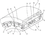
Fig. 1 shows a schematic illustration of a first exemplary embodiment of a wind power plant 1 for generating electrical energy from wind energy. The wind power plant 1 comprises a nacelle 2 which is rotatably accommodated on a tower 3. The nacelle 2 comprises a nacelle housing 4 which forms the main structure of the nacelle 2. An electrical technical component, such as a generator of the wind turbine 1, is arranged in the nacelle housing 4 of the nacelle 2.
Furthermore, a rotor 5 is provided, which has a rotor hub 6 on which rotor blades 7 are arranged. The rotor hub 6 is considered part of the nacelle 2. The rotor hub 6 is rotatably mounted on the nacelle housing 4 by means of a rotor bearing 8. In particular, it is provided that a plain bearing 9 according to the invention and described in more detail is used as the rotor bearing 8.
The rotor bearing 8 for supporting the rotor hub 6 on the nacelle housing 4 of the nacelle 2 is designed to absorb radial forces 10 and axial forces 11. The axial force 11 is caused by wind force. The radial force 10 is caused by the weight of the rotor 5 and acts on the center of gravity of the rotor 5. Since the center of gravity of the rotor 5 is located outside the rotor bearing 8, a tilting moment 12 is caused in the rotor bearing 8 by the radial forces 10. The tilting moment 12 can also be caused by an uneven loading of the rotor blade 7. This tilting moment 12 can be absorbed by means of a second slide bearing which is arranged at a distance from the slide bearing 9 according to the invention.
The rotor bearing 8 according to the invention may for example have a diameter of between 0.5m and 5 m. It is of course also conceivable for the rotor bearing 8 to be smaller or larger.
Fig. 2 shows a first embodiment of a sliding bearing 9 mounted in the nacelle 2. The plain bearing 9 is shown in a perspective view in fig. 2. Of course, the plain bearing 9 shown in fig. 2 can also be used in all other industrial applications than wind power plants.
As can be seen from fig. 2, the plain bearing 9 has an inner ring element 13 and an outer ring element 14. Between the inner ring element 13 and the outer ring element 14, a plain bearing element 15 is provided for rotational sliding bearing of the inner ring element 13 relative to the outer ring element 14.
In the embodiment shown in fig. 2, an inner circumferential surface 16 is formed on the inner ring element 13, which inner circumferential surface has a cylindrical shape and serves to accommodate a rotor shaft 17 or another shaft. The rotor shaft 17 is schematically shown in fig. 2. It can also be provided that the outer ring element 14 is coupled to the pod housing 4 by means of a bearing block 18. In the exemplary embodiment shown in fig. 2, it is therefore provided that the outer ring element 14 is rigidly coupled to the nacelle housing 4 and that the inner ring element 13 is rotatable relative to the outer ring element 14 about the rotor axis 19 by means of the plain bearing elements 15. Since the rotor shaft 17 coupled to the rotor hub 6 and thus to the rotor 5 is accommodated in the inner ring element 13, the rotor shaft 17 is rotatably accommodated in the nacelle housing 4 by means of the slide bearing 9.
The slide bearing 9 is illustrated in a perspective cross-sectional view in fig. 3. As can be seen from fig. 3, the plain bearing element 15 comprises a plurality of individual plain bearing pads 20 which are arranged distributed over the circumference between the inner ring element 13 and the outer ring element 14.
The sliding bearing pads 20 are each coupled to the inner ring element 13 by means of a fixing device 21. In particular, it is provided that the fastening device 21 is arranged between the plain bearing pad 20 and the inner ring element 13. The fixing means 21 are themselves arranged on the inner ring element 13 and serve as a support for the respective sliding bearing pads 20.
The sliding bearing pad 20 has a fixing profile 22 which is coupled with a first profile element 23 of the fixing device 21.
Furthermore, a receiving contour 24 is formed in the inner ring element 13, which is coupled to a second contour element 25 of the fastening device 21.
As can be seen particularly clearly from fig. 3, the connection between the fixing profile 22 and the first profile element 23 of the fixing device 21 is configured as a dovetail connection. The first profile-element 23 can thus be pushed axially into the fixing profile 22.
Similarly, the receiving contour 24 and the second contour element 25 of the fastening device 21 are also designed as a dovetail connection. The second profile element 25 can thus be pushed axially into the receiving profile 24.
Thus, the sliding bearing pad 20 is releasably received on the inner ring element 13 by means of the fixing device 21.
Each sliding bearing pad 20 is shown in perspective view in fig. 4 and 5, respectively. Further configurations of the slide bearing 9, in particular of the slide bearing pad 20, are explained in connection with fig. 3, 4 and 5.
As can be seen from fig. 3, 4 and 5, it can be provided that the fastening profile 22 or the receiving profile 24 is designed as a slot of a dovetail connection. The first profile element 23 and the second profile element 25 of the fixing device 21 can thus be configured correspondingly as a tongue.
As an alternative thereto, it is of course also conceivable for the first profile element 23 and the second profile element 25 of the fastening device 21 to be configured as grooves and for the fastening profile 22 or the receiving profile 24 to be configured as tongues.
The respective fixing device 21 can therefore be pushed into the receiving contour 24 of the inner ring element 13 or into the fixing contour 22 of the sliding bearing pad 20 or removed therefrom again in the axial direction of the rotor axis 19. This provides for simple replacement or simple assembly of the individual sliding bearing pads 20. Furthermore, a good connection of the respective sliding bearing pad 20 to the inner ring element 13 by means of a form-locking dovetail connection can be achieved by means of the dovetail connection.
The individual plain bearing pads 20 are therefore connected fixedly to the inner ring element 13 in the operating state of the plain bearing 9 by the described construction and therefore rotate together with the inner ring element relative to the outer ring element 14. In order to be able to realize a rotational movement between the inner ring element 13 and the outer ring element 14, a bearing surface 26 is formed on each slide bearing pad 20 opposite the fastening contour 22, which bearing surface in the ready state of the slide bearing 9 bears against a mating surface 27 of the outer ring element 14. A mating surface 27 is provided on the inner side 28 of the outer ring element 14. The bearing surface 26 of the plain bearing pad 20 and the mating surface 27 of the outer ring element 14 are designed as sliding surfaces which slide against one another during operation of the plain bearing 9. In particular, it can be provided that the mating surface 27 of the outer ring element 14 is designed as a hard wear-resistant surface, which is made of hardened steel, for example. The bearing surface 26 of the plain bearing pad 20 may be made of a relatively soft plain bearing material compared to the mating surface 27. It is of course also conceivable for the bearing surface 26 to have a sliding coating.
As can be seen particularly clearly in fig. 3, the bearing surface 26 is designed in the form of a spherical cap. The advantage of configuring the bearing surface 26 or the mating surface 27 in the form of a spherical cap is: the sliding bearing pad 20 can simply be rotated about the rotor axis 19. At the same time, the plain bearing pads 20 can be inclined at an angle to the longitudinal extension of the rotor axis 19. The curvature of the rotor shaft 17 in the plain bearing 9 can therefore be compensated for by the described spherical cap design without increasing the surface load on the bearing surface 26.
Furthermore, axial bearing forces can also be transmitted in addition to radial bearing forces by configuring the bearing surface 26 or the mating surface 27 in the form of a spherical cap.
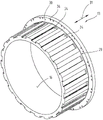
Fig. 6 shows a perspective view of the inner ring element 13. As can be seen in connection with fig. 3 to 6, the respective receiving contour 24 is arranged on an outer side 29 of the inner ring element 13. In particular, it is provided that the individual receiving contours 24 are arranged uniformly distributed over the circumference on the inner ring element 13. Each receiving contour 24 is thus intended to receive one sliding bearing pad 20.
As can be seen particularly clearly in fig. 6, an axial stop 30 is formed on the outer side 29 of the inner ring element 13, which axial stop serves to position the plain bearing pad 20 in the axial direction 31. As can be seen from fig. 6, the axial stop 30 can be configured as a shoulder.
Furthermore, it can be provided that an end face 32 of the plain bearing pad 20 bears against the axial stop 30 in the mounted state of the plain bearing pad 20. Thereby, the sliding bearing pad 20 can be axially positioned.
As can be seen particularly clearly in fig. 3, it can furthermore be provided that the sliding bearing pad 20 is pressed against the axial stop in the axial direction 31 by means of a fastening element 33, such as a screw, in particular an expansion screw. The fastening element 33 can be screwed into a threaded hole 34 formed in the axial stop 30.
Fig. 7 shows a perspective view of the inner ring element 13 with the sliding bearing pad 20 arranged thereon. To better illustrate the function of the connection between each slide bearing pad 20 and the inner ring element 13, one of the slide bearing pads 20 is pushed aside.
As can be seen from fig. 7, a fastening device 21 can be provided for fastening the plain bearing pad 20 in the inner ring element 13. The fixing means 21 can in particular act between or be arranged between the fixing contour 22 of the sliding bearing pad 20 and the receiving contour 24 of the inner ring element 13.
As can also be seen from fig. 7, the fastening device 21 has at least one first clamping wedge 36 with a wedge surface 37. In the body 35 of the fixing device 21, a mating wedge surface 38 is formed, which tapers in the axial direction 31 and interacts with the wedge surface 37. Furthermore, a first positioning device 39 is provided, by means of which the first clamping wedge 36 can be moved in the axial direction 31. The first clamping wedge 36 can extend into the first profile element 23 and the second profile element 25. In particular the dovetail of the first profile element 23 can be formed by the body 35 together with the first clamping wedge 36. Similarly, the dovetail of the second profile element 25 can be formed by the body 35 together with the first clamping wedge 36.
By moving the first clamping wedge 36 in the axial direction 31 relative to the body 35, the dovetail of the first profile element 23 or the dovetail of the second profile element 25 can be increased or decreased. Thereby, the first profile element 23 can be clamped in the fixing profile 22 or the second profile element 25 can be clamped in the receiving profile 24.
Similarly, it can be provided that the fastening device 21 has a second clamping wedge 40, which also has a wedge surface 41. This wedge-face 41 can interact with a second mating wedge-face 42 which is configured in the body 35 and tapers in the axial direction 31. The first and second mating wedge faces 38, 42 are configured to taper oppositely. The second clamping wedge 40 can be moved in the axial direction 31 by means of a second positioning device 43. In particular, it can be provided that the first positioning device 39 and the second positioning device 43 are formed on a common positioning rod 44. It can also be provided that the positioning rod 44 has an axial guide 45 which is accommodated in a positioning rod accommodation 46. The detent lever receiving portion 46 may be configured in the body 35. The axial guide 45 can be configured, for example, as a cylinder.
In particular, it can be provided that the first positioning means 39 has a left-hand thread and the second positioning means 43 has a right-hand thread, so that the two clamping wedges 36, 40 move away from one another when the positioning rod 44 is rotated in the first direction and the two clamping wedges 36, 40 move toward one another when the positioning rod 44 is rotated in the second direction. Thus, the clamp can be opened or closed by rotating the positioning lever 44. Of course, left-hand threads and right-hand threads may be interchanged.
As can be seen from the above description, the second clamping wedge 40 thus has a similar function to the first clamping wedge 36 and also forms, together with the body 35, a dovetail of the first profile element 23 or a dovetail of the second profile element 25.
The assembly of the slide bearing 9 is explained with reference to fig. 3 and 7.
In a first method step, the outer ring element 14 is fixed in its installation position, for example in the nacelle housing 4. Subsequently, the shaft on which the inner ring element 13 is arranged, such as the rotor shaft 17, is pushed in the axial direction into the outer ring element 14, but in the process the respective sliding bearing pads 20 are not yet arranged on the inner ring element 13.
The inner ring element 13 is then coaxially oriented in axial position and also in radial position with respect to the outer ring element 14.
The sliding bearing pad 20 can then be pushed in the axial direction 31 between the inner ring element 13 and the outer ring element 14. The sliding bearing pad 20 is then moved outward in the radial direction, so that the bearing surface 26 of the sliding bearing pad 20 bears against the mating surface 27. The sliding bearing pad 20 is here spaced apart from the inner ring element 13 by a distance, whereby a clearance is formed.
In a subsequent method step, the fastening device 21 is pushed in the axial direction 31 into the gap between the plain bearing pad 20 and the inner ring element 14. Here, the first profile element 23 of the fastening device 21 is pushed into the fastening profile 22 of the plain bearing pad 20 and at the same time the second profile element 25 of the fastening device 21 is pushed into the receiving profile 24 of the inner ring element 13.
When the fastening device 21 is positioned in the fastening contour 22 or in the receiving contour 24, the first clamping wedge 36 and the second clamping wedge 40 in the fastening device 21 are arranged at a distance from one another, so that the first contour element 23 of the fastening device 21 can be pushed smoothly into the fastening contour 22 of the plain bearing pad 20 and the second contour element 25 of the fastening device 21 can be pushed smoothly into the receiving contour 24 of the inner ring element 13.
The plain bearing pads 20 and the fastening device 21 are pushed onto the inner ring element 13 in the axial direction 31 until they bear against the axial stop 30 and are thus positioned in the axial direction 31. Thereby defining the axial position of the sliding bearing pad 20.
The fastening element 33 can then be screwed into the threaded bore 34 in order to fix the plain bearing pad 20 in its axial position.
The securing lever 31 can then be rotated in the tightening direction such that the two clamping wedges 36, 40 are drawn toward one another. By means of this movement of the two clamping wedges 36, 40 or wedge faces 37, 41, the first profile element 23 is clamped in the fixing profile 22 and the second profile element 25 is clamped in the receiving profile 24 by means of the clamping wedges 36, 40. The sliding bearing pad 20 is thus fixed to the inner ring element 13 by means of the fixing device 21.
Optionally, the fastening element 33 can now still be retightened.
Alternatively, it is of course also possible to apply the fixing device 21 first and only then the fastening element 33.
Then, the inner ring element 13 is rotated together with the shaft by an angle so that the next slide bearing pad 20 can be coupled with the inner ring element 13 in the above-described manner. The above process is repeated until all the receiving profiles 24 of the inner ring element 13 receive one sliding bearing pad 20.
After the assembly is completed, the shaft holding or supporting means required for the assembly can be removed, so that the shaft is supported in the bearing block 18 by means of the plain bearing 9 and is therefore ready for use.
In order to replace the individual sliding bearing pads 20, the load of the shaft need not be taken over by the external bearing device, but rather it can be provided that a single sliding bearing pad 20 is always replaced by a new sliding bearing pad 20, and the process is repeated until all sliding bearing pads 20 have been replaced. The fastening device 21 can be released and the free sliding bearing pad 20 can be pulled out of the inner ring element 13 in the axial direction 31 after the fastening device 21 has been removed.
A new slide-bearing pad 20 can then be inserted into position in the old slide-bearing pad 20 according to the above description. The newly inserted slide bearing pad 20 can then be fixed and subsequently the inner ring element 13 is rotated so that the next slide bearing pad can be replaced according to the above-described steps. This process may be repeated until all of the sliding bearing pads 20 have been replaced.
The examples show possible embodiments, it being pointed out here that the invention is not limited to the specifically shown embodiments, but that various embodiments can also be combined with one another in different ways, and that the person skilled in the art is able to realize the described possibilities of modification on the basis of the teaching of the technical means of the invention.
The scope of protection is determined by the claims. The specification and drawings are to be regarded in an illustrative manner. Individual features or combinations of features of different embodiments shown and described may constitute independent, inventive solutions per se. The task on which the independent inventive solution is based can be derived from the description.
All references to ranges within this specification are to be understood as including any and all subranges between: the statements 1 to 10 are to be understood as including all part-ranges from the lower limit 1 to the upper limit 10, i.e. all part-ranges begin with a lower limit value of 1 or more and end with an upper limit value of 10 or less, for example 1 to 1.7 or 3.2 to 8.1 or 5.5 to 10.
Finally, according to the regulations: elements have not been shown to scale and/or have been enlarged and/or reduced in size in order to provide a better understanding of the structure.
List of reference numerals
1 wind power plant
2 nacelle
3 Tower frame
4 pod housing
5 rotor
6 rotor hub
7 rotor blade
8 rotor bearing
9 sliding bearing
10 radial force
11 axial force
12 moment of tilt
13 inner ring element
14 outer ring element
15 plain bearing element
16 inner peripheral surface of inner ring member
17 rotor shaft
18 bearing seat
19 rotor axis
20 sliding bearing pad
21 fixing device
22 fixed profile
23 first profile element
24 containment profile
25 second profile element
26 bearing surface
27 mating surface
28 inner side
29 outside
30 axial stop
31 axial direction
32 end faces of sliding bearing pads
33 fastening element
34 threaded hole
35 main body
36 first clamping wedge
37 wedge surface of the first clamping wedge
38 first mating wedge surface
39 first positioning device
40 second clamping wedge
41 wedge surface of the second clamping wedge
42 second mating wedge face
43 second positioning device
44 positioning rod
45 axial guide device
46 positioning rod accommodating part
Claims (14)
1. A sliding bearing (9) comprising:
-an inner ring element (13);
-an outer ring element (14);
-at least one plain bearing element (15) arranged between the inner ring element (13) and the outer ring element (14),
characterized in that the plain bearing element (15) has a plurality of plain bearing pads (20), each plain bearing pad (20) having a bearing surface (26) in the form of a spherical cap.
2. The plain bearing (9) according to claim 1, characterized in that the individual plain bearing pads (20) each have a fastening contour (22) opposite the bearing surface (26), and in that the inner ring element (13) has on its radial outer side (29) at least one receiving contour (24) for positively connecting the plain bearing pads (20) to the inner ring element (13).
3. A plain bearing (9) according to claim 2, characterized in that a fixing means (21) is constructed, which is arranged between the plain bearing pad (20) and the inner ring element (13), the fixing means (21) being coupled with the fixing profile (22) and the receiving profile (24).
4. A plain bearing (9) according to claim 3, characterized in that the fixing means (21) have a first profile element (23) coupled with the fixing profile (22) and on the opposite side have a second profile element (25) coupled with the receiving profile (24).
5. A plain bearing (9) according to claim 3 or 4, characterized in that the fixing profile (22) and the first profile element (23) are configured as a dovetail connection and/or the receiving profile (24) and the second profile element (25) are configured as a dovetail connection.
6. A plain bearing (9) according to any one of claims 3 to 5, characterized in that the fixing means (21) comprise a main body (35) and at least one first clamping wedge (36) having a wedge surface (37) which interacts with a first mating wedge surface (38) which is constructed in the main body (35) and tapers in the axial direction (31), the first clamping wedge (36) being movable in the axial direction (31) relative to the main body (35) by means of a first positioning means (39), in particular a threaded element.
7. The plain bearing (9) according to claim 6, characterized in that the fixing means (21) comprise a second clamping wedge (40) having a wedge face (41) which interacts with a second mating wedge face (42) which is constructed in the body (35) and which tapers in the axial direction (31), the first mating wedge face (38) and the second mating wedge face (42) being constructed so as to taper oppositely, the second clamping wedge (40) being movable in the axial direction (31) by means of a second positioning means (43), in particular a threaded element.
8. A plain bearing (9) according to claim 7, characterized in that the first positioning means (39) and the second positioning means (43) are configured on one common positioning rod (44), the first positioning means (39) having a right-hand thread and the second positioning means (43) having a left-hand thread.
9. The plain bearing (9) according to one of claims 6 to 9, characterized in that the first clamping wedge (36) and/or the second clamping wedge (40) are configured such that they extend into the fixing profile (22) and the receiving profile (24).
10. The plain bearing (9) according to any one of the preceding claims, characterized in that an axial stop (30) for the plain bearing pad (20) is configured on the inner ring element (13) in the region of the receiving contour (24).
11. A plain bearing (9) according to claim 10, characterized in that a fastening element (33) is provided, by means of which the plain bearing pad (20) is pressed in the axial direction against the axial stop (30).
12. Nacelle (2) for a wind power plant (1), the nacelle (2) comprising:
-a nacelle housing (4);
-a rotor hub (6);
-a rotor bearing (8) for supporting the rotor hub (6) on the nacelle housing (4), characterized in that the rotor bearing (8) comprises a slide bearing (9) according to any of the preceding claims.
13. Wind power plant (1) having a nacelle (2), the nacelle (2) comprising:
-a nacelle housing (4);
-a rotor hub (6) on which rotor blades are arranged;
a rotor bearing (8) for supporting the rotor hub (6) on the nacelle housing (4),
characterized in that the rotor bearing (8) comprises a plain bearing (9) according to any one of claims 1 to 11.
14. Method for replacing a sliding bearing pad (20) in a sliding bearing (9) according to any one of claims 1 to 11, characterized by the following method steps:
-releasing one of the fixing means (21) by axially moving the profiled element (23, 25);
-axially pulling out the fixing means (21) of the associated sliding bearing pad (20) from the interspace between the inner ring element (13) and the sliding bearing pad (20);
-removing the sliding bearing pad (20) by moving the sliding bearing pad (20) radially inwards and subsequently axially pulling the sliding bearing pad (20) out of the inner ring element (13);
-inserting a new sliding bearing pad (20) by pushing the sliding bearing pad (20) axially and subsequently moving the sliding bearing pad (20) radially outwards;
-axially pushing the fixing means (21) of the associated sliding bearing pad (20) into the interspace between the inner ring element (13) and the sliding bearing pad (20), coupling the sliding bearing pad (20) with the inner ring element (13) by means of the fixing means (21);
-fixing the sliding bearing pad (20) by axially moving the profiled element (23, 25).
Applications Claiming Priority (3)
| Application Number | Priority Date | Filing Date | Title |
|---|---|---|---|
| ATA50183/2019A AT522164B1 (en) | 2019-03-07 | 2019-03-07 | Plain bearing |
| ATA50183/2019 | 2019-03-07 | ||
| PCT/AT2020/060064 WO2020176919A1 (en) | 2019-03-07 | 2020-03-04 | Plain bearing arrangement |
Publications (1)
| Publication Number | Publication Date |
|---|---|
| CN113574285A true CN113574285A (en) | 2021-10-29 |
Family
ID=70285338
Family Applications (1)
| Application Number | Title | Priority Date | Filing Date |
|---|---|---|---|
| CN202080018031.3A Pending CN113574285A (en) | 2019-03-07 | 2020-03-04 | Sliding bearing |
Country Status (8)
| Country | Link |
|---|---|
| US (1) | US20220145862A1 (en) |
| EP (1) | EP3947993B1 (en) |
| JP (2) | JP2022524048A (en) |
| CN (1) | CN113574285A (en) |
| AT (1) | AT522164B1 (en) |
| DK (1) | DK3947993T3 (en) |
| ES (1) | ES2963354T3 (en) |
| WO (1) | WO2020176919A1 (en) |
Families Citing this family (5)
| Publication number | Priority date | Publication date | Assignee | Title |
|---|---|---|---|---|
| DE102020126284A1 (en) * | 2020-10-07 | 2022-04-07 | Miba Gleitlager Austria Gmbh | Plain bearing, and a gondola equipped with the plain bearing for a wind turbine and a wind turbine |
| JP2023551030A (en) * | 2020-11-30 | 2023-12-06 | ミバ・グライトラーガー・オーストリア・ゲゼルシャフト・ミト・ベシュレンクテル・ハフツング | How to replace the plain bearing pad located on the rotor shaft of a wind turbine rotor bearing |
| AT524318B1 (en) * | 2020-11-30 | 2022-05-15 | Miba Gleitlager Austria Gmbh | Plain bearing, and a gondola equipped with the plain bearing for a wind turbine |
| US20240018996A1 (en) * | 2020-11-30 | 2024-01-18 | Miba Gleitlager Austria Gmbh | Plain bearing arrangement and nacelle equipped with a plain bearing arrangement for a wind turbine |
| WO2024011273A1 (en) * | 2022-07-12 | 2024-01-18 | Miba Gleitlager Austria Gmbh | Plain bearing arrangement, nacelle equipped with the plain bearing arrangement for a wind power plant, and wind power plant |
Citations (10)
| Publication number | Priority date | Publication date | Assignee | Title |
|---|---|---|---|---|
| DE531749C (en) * | 1930-09-07 | 1931-08-18 | Nomy Ab | Block storage |
| GB387196A (en) * | 1931-05-23 | 1933-02-02 | Nomy Ab | Improvements in or relating to bearings |
| GB396808A (en) * | 1931-02-13 | 1933-08-14 | Nomy Ab | Improvements in or relating to tiltable block bearings |
| DE650737C (en) * | 1936-06-11 | 1937-09-30 | Kugelfischer Erste Automatisch | bearings |
| DE678930C (en) * | 1935-09-16 | 1939-07-26 | Fast Bearing Company | warehouse |
| FR1464065A (en) * | 1965-11-17 | 1966-07-22 | Advanced plain bearing | |
| CN103998774A (en) * | 2011-12-22 | 2014-08-20 | 西门子公司 | Method for operating a wind turbine |
| CN106170633A (en) * | 2014-11-20 | 2016-11-30 | 三菱重工业株式会社 | Tilting pad sheet bearing |
| CN107448365A (en) * | 2016-05-31 | 2017-12-08 | 西门子公司 | Wind turbine including sliding bearing |
| CN107664161A (en) * | 2016-07-29 | 2018-02-06 | 西门子公司 | Bearing arrangement |
Family Cites Families (9)
| Publication number | Priority date | Publication date | Assignee | Title |
|---|---|---|---|---|
| US2167882A (en) * | 1935-09-16 | 1939-08-01 | Gustave Fast Engineering Corp | Block bearing |
| DE826807C (en) * | 1949-10-28 | 1952-01-07 | Georg Seelmann Eggebert Dipl I | Ready-to-install plain bearing |
| NL2003925C2 (en) * | 2009-12-08 | 2011-06-09 | Lagerwey Wind B V | Main bearing for a wind turbine. |
| AT509625B1 (en) | 2010-04-14 | 2012-02-15 | Miba Gleitlager Gmbh | BEARING ELEMENT |
| DE102013211710C5 (en) * | 2013-06-20 | 2016-11-10 | Siemens Aktiengesellschaft | Wind turbine with a plain bearing |
| EP2902647A1 (en) * | 2014-02-03 | 2015-08-05 | Siemens Aktiengesellschaft | Bearing having a raceway with high chromium content |
| DK179046B1 (en) * | 2016-02-25 | 2017-09-18 | Envision Energy Denmark Aps | Wind turbine comprising a moment bearing |
| EP3219984B1 (en) * | 2016-03-14 | 2019-01-02 | Siemens Aktiengesellschaft | Sliding bearing arrangement for a wind turbine |
| AT522155B1 (en) * | 2019-03-07 | 2020-09-15 | Miba Gleitlager Austria Gmbh | Plain bearing |
-
2019
- 2019-03-07 AT ATA50183/2019A patent/AT522164B1/en active
-
2020
- 2020-03-04 US US17/435,201 patent/US20220145862A1/en active Pending
- 2020-03-04 ES ES20718520T patent/ES2963354T3/en active Active
- 2020-03-04 DK DK20718520.8T patent/DK3947993T3/en active
- 2020-03-04 WO PCT/AT2020/060064 patent/WO2020176919A1/en active Application Filing
- 2020-03-04 JP JP2021552877A patent/JP2022524048A/en active Pending
- 2020-03-04 EP EP20718520.8A patent/EP3947993B1/en active Active
- 2020-03-04 CN CN202080018031.3A patent/CN113574285A/en active Pending
-
2023
- 2023-08-04 JP JP2023127910A patent/JP2023160817A/en active Pending
Patent Citations (10)
| Publication number | Priority date | Publication date | Assignee | Title |
|---|---|---|---|---|
| DE531749C (en) * | 1930-09-07 | 1931-08-18 | Nomy Ab | Block storage |
| GB396808A (en) * | 1931-02-13 | 1933-08-14 | Nomy Ab | Improvements in or relating to tiltable block bearings |
| GB387196A (en) * | 1931-05-23 | 1933-02-02 | Nomy Ab | Improvements in or relating to bearings |
| DE678930C (en) * | 1935-09-16 | 1939-07-26 | Fast Bearing Company | warehouse |
| DE650737C (en) * | 1936-06-11 | 1937-09-30 | Kugelfischer Erste Automatisch | bearings |
| FR1464065A (en) * | 1965-11-17 | 1966-07-22 | Advanced plain bearing | |
| CN103998774A (en) * | 2011-12-22 | 2014-08-20 | 西门子公司 | Method for operating a wind turbine |
| CN106170633A (en) * | 2014-11-20 | 2016-11-30 | 三菱重工业株式会社 | Tilting pad sheet bearing |
| CN107448365A (en) * | 2016-05-31 | 2017-12-08 | 西门子公司 | Wind turbine including sliding bearing |
| CN107664161A (en) * | 2016-07-29 | 2018-02-06 | 西门子公司 | Bearing arrangement |
Also Published As
| Publication number | Publication date |
|---|---|
| ES2963354T3 (en) | 2024-03-26 |
| JP2023160817A (en) | 2023-11-02 |
| AT522164A4 (en) | 2020-09-15 |
| EP3947993A1 (en) | 2022-02-09 |
| JP2022524048A (en) | 2022-04-27 |
| DK3947993T3 (en) | 2023-11-06 |
| US20220145862A1 (en) | 2022-05-12 |
| EP3947993B1 (en) | 2023-08-02 |
| AT522164B1 (en) | 2020-09-15 |
| WO2020176919A1 (en) | 2020-09-10 |
Similar Documents
| Publication | Publication Date | Title |
|---|---|---|
| CN113574285A (en) | Sliding bearing | |
| DK2381092T3 (en) | Systems and methods for mounting a rotor locking device for use in a wind turbine | |
| US8669685B2 (en) | Wind power turbine for producing electric energy | |
| EP2715121B1 (en) | Elastomeric teetering hinge | |
| CN113498456A (en) | Sliding bearing | |
| EP3460270B1 (en) | Wind turbine with tilting pad thrust bearing | |
| US8858382B2 (en) | Pin retainer | |
| CN102237750A (en) | Wind power turbine electric generator, and wind power turbine equipped with such an electric generator | |
| KR20110084958A (en) | Wind-driven generator device | |
| US9273732B2 (en) | Bearing with a supporting element and method of supporting a first ring of a bearing | |
| US10612516B2 (en) | Wind turbine | |
| EP3085957B1 (en) | Slewing bearing device for a wind turbine | |
| CA2764165A1 (en) | Wind turbine blade bearing | |
| WO2015022311A1 (en) | Bearing arrangement of radial and thrust spherical bearings | |
| EP3594490B1 (en) | Yaw bearing arrangement | |
| WO2015022309A1 (en) | Bearing assembly with mounting for spherical plain bearing | |
| CN105074204A (en) | A hub and bearing system and a turbine comprising the hub and bearing system | |
| CN116368308A (en) | Sliding bearing device, nacelle for a wind power installation and wind power installation equipped with a sliding bearing device | |
| CN109751193B (en) | Wind generating set | |
| JP2024517343A (en) | Nacelle for wind turbine | |
| CN116568923A (en) | Sliding bearing and nacelle for a wind power installation equipped with a sliding bearing | |
| EP2981713B1 (en) | A hub and bearing system and a turbine comprising the hub and bearing system |
Legal Events
| Date | Code | Title | Description |
|---|---|---|---|
| PB01 | Publication | ||
| PB01 | Publication | ||
| SE01 | Entry into force of request for substantive examination | ||
| SE01 | Entry into force of request for substantive examination |