CN113562539A - Automatic winder for fiber reinforced bar - Google Patents
Automatic winder for fiber reinforced bar Download PDFInfo
- Publication number
- CN113562539A CN113562539A CN202110920352.9A CN202110920352A CN113562539A CN 113562539 A CN113562539 A CN 113562539A CN 202110920352 A CN202110920352 A CN 202110920352A CN 113562539 A CN113562539 A CN 113562539A
- Authority
- CN
- China
- Prior art keywords
- rigid coupling
- winding
- swing mechanism
- fiber reinforced
- fixedly connected
- Prior art date
- Legal status (The legal status is an assumption and is not a legal conclusion. Google has not performed a legal analysis and makes no representation as to the accuracy of the status listed.)
- Pending
Links
- 239000000835 fiber Substances 0.000 title claims abstract description 56
- 238000004804 winding Methods 0.000 claims abstract description 65
- 230000008878 coupling Effects 0.000 claims abstract description 25
- 238000010168 coupling process Methods 0.000 claims abstract description 25
- 238000005859 coupling reaction Methods 0.000 claims abstract description 25
- 238000005096 rolling process Methods 0.000 claims description 15
- 230000002787 reinforcement Effects 0.000 claims description 14
- 229910000831 Steel Inorganic materials 0.000 description 14
- 239000010959 steel Substances 0.000 description 14
- 238000004519 manufacturing process Methods 0.000 description 7
- 230000005540 biological transmission Effects 0.000 description 2
- 230000003014 reinforcing effect Effects 0.000 description 2
- 239000012783 reinforcing fiber Substances 0.000 description 2
- 235000017166 Bambusa arundinacea Nutrition 0.000 description 1
- 235000017491 Bambusa tulda Nutrition 0.000 description 1
- 241001330002 Bambuseae Species 0.000 description 1
- 229920002748 Basalt fiber Polymers 0.000 description 1
- 235000015334 Phyllostachys viridis Nutrition 0.000 description 1
- 230000004075 alteration Effects 0.000 description 1
- 239000012752 auxiliary agent Substances 0.000 description 1
- 239000011425 bamboo Substances 0.000 description 1
- 230000009286 beneficial effect Effects 0.000 description 1
- 238000005056 compaction Methods 0.000 description 1
- 239000002131 composite material Substances 0.000 description 1
- 238000007599 discharging Methods 0.000 description 1
- 230000000694 effects Effects 0.000 description 1
- 238000005516 engineering process Methods 0.000 description 1
- 239000003365 glass fiber Substances 0.000 description 1
- 238000009434 installation Methods 0.000 description 1
- 239000000463 material Substances 0.000 description 1
- 238000012986 modification Methods 0.000 description 1
- 230000004048 modification Effects 0.000 description 1
- 238000000465 moulding Methods 0.000 description 1
- 238000012856 packing Methods 0.000 description 1
- 230000000149 penetrating effect Effects 0.000 description 1
- 239000012779 reinforcing material Substances 0.000 description 1
- 238000006467 substitution reaction Methods 0.000 description 1
- 229920003002 synthetic resin Polymers 0.000 description 1
- 239000000057 synthetic resin Substances 0.000 description 1
Images


Classifications
-
- B—PERFORMING OPERATIONS; TRANSPORTING
- B65—CONVEYING; PACKING; STORING; HANDLING THIN OR FILAMENTARY MATERIAL
- B65H—HANDLING THIN OR FILAMENTARY MATERIAL, e.g. SHEETS, WEBS, CABLES
- B65H54/00—Winding, coiling, or depositing filamentary material
- B65H54/02—Winding and traversing material on to reels, bobbins, tubes, or like package cores or formers
- B65H54/28—Traversing devices; Package-shaping arrangements
- B65H54/36—Yarn-guide advancing or raising mechanisms, e.g. cop-building arrangements
-
- B—PERFORMING OPERATIONS; TRANSPORTING
- B65—CONVEYING; PACKING; STORING; HANDLING THIN OR FILAMENTARY MATERIAL
- B65H—HANDLING THIN OR FILAMENTARY MATERIAL, e.g. SHEETS, WEBS, CABLES
- B65H54/00—Winding, coiling, or depositing filamentary material
- B65H54/02—Winding and traversing material on to reels, bobbins, tubes, or like package cores or formers
- B65H54/40—Arrangements for rotating packages
- B65H54/54—Arrangements for supporting cores or formers at winding stations; Securing cores or formers to driving members
- B65H54/547—Cantilever supporting arrangements
-
- B—PERFORMING OPERATIONS; TRANSPORTING
- B65—CONVEYING; PACKING; STORING; HANDLING THIN OR FILAMENTARY MATERIAL
- B65H—HANDLING THIN OR FILAMENTARY MATERIAL, e.g. SHEETS, WEBS, CABLES
- B65H54/00—Winding, coiling, or depositing filamentary material
- B65H54/70—Other constructional features of yarn-winding machines
-
- B—PERFORMING OPERATIONS; TRANSPORTING
- B65—CONVEYING; PACKING; STORING; HANDLING THIN OR FILAMENTARY MATERIAL
- B65H—HANDLING THIN OR FILAMENTARY MATERIAL, e.g. SHEETS, WEBS, CABLES
- B65H57/00—Guides for filamentary materials; Supports therefor
- B65H57/12—Tubes
-
- B—PERFORMING OPERATIONS; TRANSPORTING
- B65—CONVEYING; PACKING; STORING; HANDLING THIN OR FILAMENTARY MATERIAL
- B65H—HANDLING THIN OR FILAMENTARY MATERIAL, e.g. SHEETS, WEBS, CABLES
- B65H75/00—Storing webs, tapes, or filamentary material, e.g. on reels
- B65H75/02—Cores, formers, supports, or holders for coiled, wound, or folded material, e.g. reels, spindles, bobbins, cop tubes, cans, mandrels or chucks
- B65H75/04—Kinds or types
- B65H75/08—Kinds or types of circular or polygonal cross-section
- B65H75/12—Kinds or types of circular or polygonal cross-section with a single end flange (e.g. with a conical end flange); formed with one end of greater diameter than the barrel
-
- B—PERFORMING OPERATIONS; TRANSPORTING
- B65—CONVEYING; PACKING; STORING; HANDLING THIN OR FILAMENTARY MATERIAL
- B65H—HANDLING THIN OR FILAMENTARY MATERIAL, e.g. SHEETS, WEBS, CABLES
- B65H75/00—Storing webs, tapes, or filamentary material, e.g. on reels
- B65H75/02—Cores, formers, supports, or holders for coiled, wound, or folded material, e.g. reels, spindles, bobbins, cop tubes, cans, mandrels or chucks
- B65H75/18—Constructional details
- B65H75/24—Constructional details adjustable in configuration, e.g. expansible
-
- B—PERFORMING OPERATIONS; TRANSPORTING
- B65—CONVEYING; PACKING; STORING; HANDLING THIN OR FILAMENTARY MATERIAL
- B65H—HANDLING THIN OR FILAMENTARY MATERIAL, e.g. SHEETS, WEBS, CABLES
- B65H2701/00—Handled material; Storage means
- B65H2701/30—Handled filamentary material
- B65H2701/39—Other types of filamentary materials or special applications
Landscapes
- Engineering & Computer Science (AREA)
- Textile Engineering (AREA)
- Structural Engineering (AREA)
- Moulding By Coating Moulds (AREA)
Abstract
The invention discloses an automatic winding machine for fiber reinforced bars, which comprises a base and a fixed seat, wherein the top of the base is fixedly connected with a rack, the top of the rack is rotatably provided with a rotating shaft by a hoop matched with a bearing, one end of the rotating shaft is coaxially and fixedly connected with a connecting disc, the connecting disc is fixedly connected with a plurality of winding frames, and one side of each winding frame, which is far away from the connecting disc, is provided with a limiting assembly in a sliding manner; the top rigid coupling of fixing base has electric telescopic handle, and electric telescopic handle's top removal end is connected with swing mechanism, and swing mechanism's top is connected with the mounting panel, and one side rigid coupling of swing mechanism has the stand pipe, and one side rigid coupling of stand pipe has the bracing piece, and the one end rigid coupling that the stand pipe was kept away from to the bracing piece is on swing mechanism.
Description
Technical Field
The invention relates to the technical field of fiber reinforced bar winding, in particular to an automatic winding machine for fiber reinforced bars.
Background
The fiber reinforced bar (fiber reinforced bar) is a new type composite material formed by using high-strength glass fiber, basalt fiber and the like as reinforcing materials and synthetic resin, auxiliary agents and the like as base materials through pultrusion and traction molding.
After the production of the fiber reinforced bar is finished, the fiber reinforced bar needs to be wound, the existing winding machine drives the winding roller to wind the fiber reinforced bar through the motor, the winding roller driven by the motor needs to accurately regulate and control the rotating speed of the motor, and the speed of the winding roller is required to be consistent with the speed of a transmission tractor of a production line, so that the fiber reinforced bar is synchronously wound, the fiber reinforced bar is pulled out and wound without discharging, the integrity of the fiber reinforced bar is damaged, and the yield of the fiber reinforced bar is influenced; when the rotational speed of motor was slower, the reinforcing bar fastening nature of rolling was relatively poor, takes place loosely to drop easily, is unfavorable for later stage storage, and we propose a reinforcing bar automatic winding machine for this reason and be used for solving above-mentioned problem.
Disclosure of Invention
The invention aims to provide an automatic winder for fiber reinforced bars, which aims to solve the problems in the background technology.
In order to achieve the purpose, the invention provides the following technical scheme: an automatic winding machine for fiber reinforced bars comprises a base and a fixed seat, wherein the top of the base is fixedly connected with a rack, the top of the rack is rotatably provided with a rotating shaft through a hoop matched with a bearing, one end of the rotating shaft is coaxially and fixedly connected with a connecting disc, the connecting disc is fixedly connected with a plurality of winding frames, and one side, away from the connecting disc, of each winding frame is slidably provided with a limiting assembly;
the utility model discloses a swing mechanism, including fixing base, swing mechanism, stand, electric telescopic handle, swing mechanism's top rigid coupling has electric telescopic handle, electric telescopic handle's top removal end is connected with swing mechanism, swing mechanism's top is connected with the mounting panel, one side rigid coupling of swing mechanism has the stand, one side rigid coupling of stand has the bracing piece, the one end rigid coupling that the stand was kept away from to the bracing piece is on swing mechanism.
Preferably, the winding frame is provided with a plurality of winding frames in an annular array by taking the axis of the connecting disc as an array point, and the winding frame is completely consistent in structure.
Preferably, the winding frame is of an Contraband-shaped structure, two ends of one side, far away from the connecting disc, of the winding frame penetrate through a linear sliding groove, and the limiting assembly penetrates through the sliding groove through a bolt to be tightly installed in the winding frame.
Preferably, the limiting assembly comprises a limiting block, the limiting block is slidably mounted in the winding frame, a winding rod is fixedly connected to one end of the limiting block, and a limiting rod is fixedly connected to one end, far away from the limiting block, of the winding rod.
Preferably, swing mechanism includes spacing post, the coaxial rigid coupling of low side of spacing post is held in electric telescopic handle's removal, the top rigid coupling of spacing post the mounting panel, the middle part axle body indent of spacing post is equipped with the ring channel, the turning block is installed to the ring channel internal rotation, the fixed overcoat of turning block has a rotating cylinder, rotating cylinder rotates the overcoat and is on spacing post, the coaxial fixed overcoat in upper end of rotating cylinder has driven gear, driven gear meshing is connected with the driving gear, the coaxial rigid coupling of driving gear is on positive and negative motor's output shaft, positive and negative motor's top rigid coupling is in one side of mounting panel.
Preferably, the guide tube and the support rod are fixedly connected outside the rotating cylinder, and the rotating cylinder, the guide tube and the support rod form a triangular structure.
Compared with the prior art, the invention has the beneficial effects that: the fiber reinforcement is driven to transmit through the feeding force of the fiber reinforcement tractor on the fiber reinforcement production line, one end of the fiber reinforcement abuts against the winding rod, the feeding force of the fiber reinforcement tractor and the deformation force of the self deformation of the fiber reinforcement further drive the winding frame to rotate, the winding of the fiber reinforcement under the unpowered condition is realized, the winding power comes from the transmission feeding force and the self deformation force of the fiber reinforcement, the winding synchronism of the fiber reinforcement is ensured, and the yield of the fiber reinforcement production is ensured; the chute of the winding frame is matched with the limiting block through the bolt, so that winding with different diameters can be performed, and the application range is wider; the swing mechanism connected with the guide pipe ensures that fiber reinforced steel bars can be flatly arranged on the winding frame when being wound, and the flatness and compactness of winding are ensured.
Drawings
FIG. 1 is a schematic structural view of the present invention;
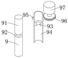
FIG. 2 is a partial sectional structural view of the swing mechanism of the present invention;
fig. 3 is a schematic side view of the rolling operation of the present invention.
In the figure: 1. a base; 2. a frame; 3. a rotating shaft; 4. a connecting disc; 5. a winding frame; 6. a limiting component; 61. a limiting rod; 62. a limiting block; 63. winding the rod; 7. a fixed seat; 8. an electric telescopic rod; 9. a swing mechanism; 91. a limiting column; 92. an annular groove; 93. rotating the block; 94. a rotating cylinder; 95. a driven gear; 96. a driving gear; 97. a positive and negative motor; 10. a guide tube; 11. a support bar; 12. and (7) mounting the plate.
Detailed Description
The technical solutions in the embodiments of the present invention will be clearly and completely described below with reference to the drawings in the embodiments of the present invention, and it is obvious that the described embodiments are only a part of the embodiments of the present invention, and not all of the embodiments. All other embodiments, which can be derived by a person skilled in the art from the embodiments given herein without making any creative effort, shall fall within the protection scope of the present invention.
Referring to fig. 1-3, the present invention provides a technical solution: the utility model provides a fiber reinforcement automatic winding machine, including base 1 and fixing base 7, during the use, use expansion bolts to install base 1 and fixing base 7 respectively at the discharge end of fiber reinforcement production line, the top rigid coupling of base 1 has frame 2, the top of frame 2 is passed through staple bolt cooperation bearing and is rotated and install axis of rotation 3, the coaxial rigid coupling of one end of axis of rotation 3 has connection pad 4, the rigid coupling has a plurality of rolling frame 5 on connection pad 4, rolling frame 5 uses the axle center of connection pad 4 to be equipped with a plurality of as array point annular array, the structure on the rolling frame 5 is identical completely. The winding frame 5 is of an Contraband-shaped structure, two ends of one side, far away from the connecting disc 4, of the winding frame penetrate through the linear sliding grooves, and the limiting assembly 6 penetrates through the sliding grooves through bolts to be tightly installed in the winding frame 5. The limiting assembly 6 at the side end of the winding frame 5 can be adjusted by loosening the bolt, so that the winding frame is suitable for winding fiber reinforced steel bars with different diameters and sizes, and the application range is wider;
as shown in fig. 1, a limiting assembly 6 is slidably mounted on one side of the winding frame 5 away from the connecting disc 4; the limiting assembly 6 comprises a limiting block 62, the limiting block 62 is slidably mounted in the winding frame 5, a winding rod 63 is fixedly connected to one end of the limiting block 62, and a limiting rod 61 is fixedly connected to one end, far away from the limiting block 62, of the winding rod 63.
As shown in fig. 1-3, an electric telescopic rod 8 is fixedly connected to the top of the fixing seat 7, a swing mechanism 9 is connected to the top moving end of the electric telescopic rod 8, an installation plate 12 is connected to the top of the swing mechanism 9, a guide tube 10 is fixedly connected to one side of the swing mechanism 9, a support rod 11 is fixedly connected to one side of the guide tube 10, and one end of the support rod 11, which is far away from the guide tube 10, is fixedly connected to the swing mechanism 9. The height of the guide pipe 10 is adjusted through the electric telescopic rod 8, so that the device is suitable for discharge ends with different heights; after the limiting assembly 6 is adjusted, the fiber steel bars which are produced pass through the guide pipe 10, the end parts of the fiber steel bars after passing through the guide pipe 10 abut against the winding rod 63 of the limiting assembly 6, the feeding force of a fiber steel bar tractor and the deformation force of the deformation of the fiber steel bars act on the winding frame 5 which is driven to rotate respectively, the effect is as shown in figure 3, and then the fiber steel bars are wound without power, so that the winding speed and the winding synchronism are ensured, and the yield of the fiber steel bars is further ensured;
as shown in fig. 1 and 2, the swing mechanism 9 includes a limiting column 91, the lower end of the limiting column 91 is coaxially and fixedly connected to the moving end of the electric telescopic rod 8, the top end of the limiting column 91 is fixedly connected to the mounting plate 12, a circular groove 92 is concavely formed in the middle shaft body of the limiting column 91, a rotating block 93 is rotatably mounted in the circular groove 92, a rotating cylinder 94 is fixedly sleeved outside the rotating block 93, the rotating cylinder 94 is rotatably sleeved on the limiting column 91, a driven gear 95 is coaxially and fixedly sleeved outside the upper end of the rotating cylinder 94, the driven gear 95 is engaged with a driving gear 96, the driving gear 96 is coaxially and fixedly connected to the output shaft of the positive and negative motor 97, and the top of the positive and negative motor 97 is fixedly connected to one side of the mounting plate 12. The guide tube 10 and the support rod 11 are fixedly connected outside the rotating cylinder 94, the guide tube 10 and the support rod 11 form a triangular structure, the triangular structure is more stable, and the fact that the fiber steel bars penetrating through the guide tube 10 are stirred more stably is guaranteed. Positive and negative motor 97 starts in the time of the work of rolling up frame 5, driven gear 95 through the driving gear 96 meshing connection drives a rotation section of thick bamboo 94 and rotates, rotates a 94 and then drives the swing of stand pipe 10, and the swing of stand pipe 10 drives inside reinforcing fiber bar and removes, and then can be when the rolling, and reinforcing fiber bar can level and smooth the range on rolling up frame 5, has guaranteed the roughness and the degree of packing of rolling, is difficult to loosely drop when the later stage is accomodate.
The working principle is as follows: when the fiber bar winding device is used, the base 1 and the fixed seat 7 are respectively arranged at the discharge end of a fiber bar production line by using expansion bolts, the height of the guide pipe 10 is adjusted by the electric telescopic rod 8, so that the fiber bar winding device is suitable for the discharge ends with different heights, the limit component 6 at the side end of the winding frame 5 can be adjusted by loosening the bolts, the fiber bar winding device is suitable for winding fiber bars with different diameters and sizes, and the application range is wider; after the adjustment of the limiting component 6 is completed, the fiber steel bars which are produced pass through the guide pipe 10, the end parts of the fiber steel bars pass through the guide pipe 10 and abut against the winding rod 63 of the limiting component 6, the feeding force of the fiber steel bar tractor and the deformation force of the self deformation of the fiber steel bars respectively act to drive the winding frame 5 to rotate, thereby performing unpowered rolling work on the fiber reinforced steel bars, ensuring the rolling speed and the synchronism, further ensuring the yield of the fiber reinforced bar production, simultaneously starting the positive and negative motors 97, driving the rotary cylinder 94 to rotate by the driven gear 95 meshed and connected with the driving gear 96, driving the guide tube 10 to swing by the rotary cylinder 94, driving the fiber reinforced bar inside to move by the swing of the guide tube 10, and then can be when the rolling, the arrangement that the fiber reinforcement can be level and smooth has guaranteed the roughness and the degree of compaction of rolling on rolling frame 5, is difficult to loosely drop when the later stage is accomodate.
Although embodiments of the present invention have been shown and described, it will be appreciated by those skilled in the art that changes, modifications, substitutions and alterations can be made in these embodiments without departing from the principles and spirit of the invention, the scope of which is defined in the appended claims and their equivalents.
Claims (6)
1. The utility model provides a fiber reinforcement automatic winding machine, includes base (1) and fixing base (7), its characterized in that: the winding machine is characterized in that a rack (2) is fixedly connected to the top of the base (1), a rotating shaft (3) is rotatably mounted at the top of the rack (2) through a hoop and a bearing, a connecting disc (4) is coaxially and fixedly connected to one end of the rotating shaft (3), a plurality of winding frames (5) are fixedly connected to the connecting disc (4), and a limiting assembly (6) is slidably mounted on one side, away from the connecting disc (4), of each winding frame (5);
the top rigid coupling of fixing base (7) has electric telescopic handle (8), the top removal end of electric telescopic handle (8) is connected with swing mechanism (9), the top of swing mechanism (9) is connected with mounting panel (12), one side rigid coupling of swing mechanism (9) has stand pipe (10), one side rigid coupling of stand pipe (10) has bracing piece (11), the one end rigid coupling that stand pipe (10) were kept away from in bracing piece (11) is on swing mechanism (9).
2. The automatic winder for fiber reinforced bars according to claim 1, characterized in that: the winding frame (5) is provided with a plurality of winding frames by taking the axis of the connecting disc (4) as an array point annular array, and the structures on the winding frame (5) are completely consistent.
3. The automatic winder for fiber reinforced bars according to claim 1, characterized in that: the winding frame (5) is of an Contraband-shaped structure, two ends of one side, far away from the connecting disc (4), of the winding frame penetrate through a linear sliding groove, and the limiting assembly (6) penetrates through the sliding groove through a bolt to be tightly installed in the winding frame (5).
4. The automatic winder for fiber reinforced bars according to claim 1, characterized in that: spacing subassembly (6) include stopper (62), stopper (62) slidable mounting is in rolling frame (5), the one end rigid coupling of stopper (62) has coiling pole (63), the one end rigid coupling that stopper (62) were kept away from in coiling pole (63) has gag lever post (61).
5. The automatic winder for fiber reinforced bars according to claim 1, characterized in that: swing mechanism (9) are including spacing post (91), the coaxial rigid coupling of low side of spacing post (91) is held in the removal of electric telescopic handle (8), the top rigid coupling of spacing post (91) mounting panel (12), the middle part shaft body indent of spacing post (91) is equipped with ring channel (92), turning block (93) are installed to ring channel (92) internal rotation, turning block (93) fixed overcoat has a rotating cylinder (94), rotating cylinder (94) rotate the overcoat on spacing post (91), the coaxial fixed overcoat in upper end of rotating cylinder (94) has driven gear (95), driven gear (95) meshing is connected with driving gear (96), the coaxial rigid coupling of driving gear (96) is on the output shaft of positive and negative motor (97), the top rigid coupling of positive and negative motor (97) is in one side of mounting panel (12).
6. The automatic winder for fiber reinforced bars according to claim 5, characterized in that: the guide tube (10) and the support rod (11) are fixedly connected outside the rotating cylinder (94), and the rotating cylinder (94), the guide tube (10) and the support rod (11) form a triangular structure.
Priority Applications (1)
| Application Number | Priority Date | Filing Date | Title |
|---|---|---|---|
| CN202110920352.9A CN113562539A (en) | 2021-08-11 | 2021-08-11 | Automatic winder for fiber reinforced bar |
Applications Claiming Priority (1)
| Application Number | Priority Date | Filing Date | Title |
|---|---|---|---|
| CN202110920352.9A CN113562539A (en) | 2021-08-11 | 2021-08-11 | Automatic winder for fiber reinforced bar |
Publications (1)
| Publication Number | Publication Date |
|---|---|
| CN113562539A true CN113562539A (en) | 2021-10-29 |
Family
ID=78171349
Family Applications (1)
| Application Number | Title | Priority Date | Filing Date |
|---|---|---|---|
| CN202110920352.9A Pending CN113562539A (en) | 2021-08-11 | 2021-08-11 | Automatic winder for fiber reinforced bar |
Country Status (1)
| Country | Link |
|---|---|
| CN (1) | CN113562539A (en) |
Cited By (1)
| Publication number | Priority date | Publication date | Assignee | Title |
|---|---|---|---|---|
| CN115303888A (en) * | 2022-07-04 | 2022-11-08 | 安徽中盛电气集团有限公司 | Rolling packing apparatus for cable manufacture |
Citations (12)
| Publication number | Priority date | Publication date | Assignee | Title |
|---|---|---|---|---|
| CN1847127A (en) * | 2005-04-15 | 2006-10-18 | 村田机械株式会社 | Yarn traverse apparatus |
| CN101321678A (en) * | 2005-12-10 | 2008-12-10 | 欧瑞康纺织有限及两合公司 | Thread guide |
| CN203392556U (en) * | 2013-07-19 | 2014-01-15 | 董过房 | Unpowered plastic pipe coiling device |
| CN105621149A (en) * | 2016-03-18 | 2016-06-01 | 甘肃青龙管业有限责任公司 | Plastic pipe coiling machine |
| CN108178020A (en) * | 2017-12-18 | 2018-06-19 | 贵州钢绳股份有限公司 | A kind of cord reeling method and its device for batching different circle diameter hawsers |
| CN207524749U (en) * | 2017-10-17 | 2018-06-22 | 绍兴壹佳建设有限公司 | A kind of building iron draw off gear |
| CN208964255U (en) * | 2018-08-30 | 2019-06-11 | 杭州久阳塑胶管业有限公司 | A kind of winder convenient for charging |
| CN209407108U (en) * | 2018-12-21 | 2019-09-20 | 浙江协和陶瓷有限公司 | A kind of Steel Tape Recoiler |
| CN110950189A (en) * | 2019-12-20 | 2020-04-03 | 深圳市金弘珠宝首饰有限公司 | Production facility of noble metal chain and automatic chain machine of receiving thereof |
| CN112282378A (en) * | 2020-10-20 | 2021-01-29 | 蔡家锐 | Construction steel bar location structure |
| CN212893185U (en) * | 2020-05-21 | 2021-04-06 | 浙江莱普顿管道科技有限公司 | A rolling machine for PPR coil pipe is collected |
| CN215797575U (en) * | 2021-08-11 | 2022-02-11 | 安徽森德新材料科技发展有限公司 | Automatic winder for fiber reinforced bar |
-
2021
- 2021-08-11 CN CN202110920352.9A patent/CN113562539A/en active Pending
Patent Citations (12)
| Publication number | Priority date | Publication date | Assignee | Title |
|---|---|---|---|---|
| CN1847127A (en) * | 2005-04-15 | 2006-10-18 | 村田机械株式会社 | Yarn traverse apparatus |
| CN101321678A (en) * | 2005-12-10 | 2008-12-10 | 欧瑞康纺织有限及两合公司 | Thread guide |
| CN203392556U (en) * | 2013-07-19 | 2014-01-15 | 董过房 | Unpowered plastic pipe coiling device |
| CN105621149A (en) * | 2016-03-18 | 2016-06-01 | 甘肃青龙管业有限责任公司 | Plastic pipe coiling machine |
| CN207524749U (en) * | 2017-10-17 | 2018-06-22 | 绍兴壹佳建设有限公司 | A kind of building iron draw off gear |
| CN108178020A (en) * | 2017-12-18 | 2018-06-19 | 贵州钢绳股份有限公司 | A kind of cord reeling method and its device for batching different circle diameter hawsers |
| CN208964255U (en) * | 2018-08-30 | 2019-06-11 | 杭州久阳塑胶管业有限公司 | A kind of winder convenient for charging |
| CN209407108U (en) * | 2018-12-21 | 2019-09-20 | 浙江协和陶瓷有限公司 | A kind of Steel Tape Recoiler |
| CN110950189A (en) * | 2019-12-20 | 2020-04-03 | 深圳市金弘珠宝首饰有限公司 | Production facility of noble metal chain and automatic chain machine of receiving thereof |
| CN212893185U (en) * | 2020-05-21 | 2021-04-06 | 浙江莱普顿管道科技有限公司 | A rolling machine for PPR coil pipe is collected |
| CN112282378A (en) * | 2020-10-20 | 2021-01-29 | 蔡家锐 | Construction steel bar location structure |
| CN215797575U (en) * | 2021-08-11 | 2022-02-11 | 安徽森德新材料科技发展有限公司 | Automatic winder for fiber reinforced bar |
Cited By (2)
| Publication number | Priority date | Publication date | Assignee | Title |
|---|---|---|---|---|
| CN115303888A (en) * | 2022-07-04 | 2022-11-08 | 安徽中盛电气集团有限公司 | Rolling packing apparatus for cable manufacture |
| CN115303888B (en) * | 2022-07-04 | 2024-04-26 | 安徽中盛电气集团有限公司 | Winding and packing device for cable production |
Similar Documents
| Publication | Publication Date | Title |
|---|---|---|
| CN215797575U (en) | Automatic winder for fiber reinforced bar | |
| CN113562539A (en) | Automatic winder for fiber reinforced bar | |
| CN212863533U (en) | Main tractor for erecting lead | |
| CN201580833U (en) | Hand-drive sheet iron uncoiler | |
| CN112340532A (en) | Rope device is received in construction | |
| CN212355864U (en) | Coil stock mechanism is used in waterproofing membrane production | |
| CN201003272Y (en) | Roof plaster rendering machine | |
| CN201380543Y (en) | Tension-cylinder suspended type tensioning machine | |
| CN216277660U (en) | Spiral vibration pile driving system | |
| CN201940775U (en) | Rotary driving mechanism of steel reinforcement cage weld-forming machine | |
| CN214602874U (en) | Welding positioning tool for reinforcement cage | |
| CN213325846U (en) | Fiber winding device for glass fiber reinforced plastic production | |
| CN208489311U (en) | A kind of winding head mechanism applied to quadrate lithium battery up- coiler | |
| CN207192467U (en) | A kind of wrap-up of plastic pipe | |
| CN202291146U (en) | Bending mechanism for steel bar truss web bar | |
| CN220950621U (en) | Skeleton type winding mandrel tension-adjustable winding device | |
| CN221089434U (en) | Longitudinal and tangential line locking device for aerated bricks | |
| CN113697735B (en) | Glass mounting fixture assembly system | |
| CN220806795U (en) | Steel wire polishing treatment device | |
| CN218843093U (en) | High-efficient building pile foundation protects a section of thick bamboo and demolishs device | |
| CN221184964U (en) | Aluminum plate cutting processing appurtenance | |
| CN216708420U (en) | Draw gear is used in FRP pipe production and processing | |
| CN213381357U (en) | Automatic screw-on device of combined anchor rod nut | |
| CN218509091U (en) | Planting muscle installation is with colloid injection device | |
| CN221759007U (en) | Textile fabric winding device |
Legal Events
| Date | Code | Title | Description |
|---|---|---|---|
| PB01 | Publication | ||
| PB01 | Publication | ||
| SE01 | Entry into force of request for substantive examination | ||
| SE01 | Entry into force of request for substantive examination |