CN113520626A - Self-limiting adjusting type lifting device capable of preventing arm from shaking for ophthalmic nursing - Google Patents
Self-limiting adjusting type lifting device capable of preventing arm from shaking for ophthalmic nursing Download PDFInfo
- Publication number
- CN113520626A CN113520626A CN202110718456.1A CN202110718456A CN113520626A CN 113520626 A CN113520626 A CN 113520626A CN 202110718456 A CN202110718456 A CN 202110718456A CN 113520626 A CN113520626 A CN 113520626A
- Authority
- CN
- China
- Prior art keywords
- sliding
- block
- lifting
- limiting
- lifting device
- Prior art date
- Legal status (The legal status is an assumption and is not a legal conclusion. Google has not performed a legal analysis and makes no representation as to the accuracy of the status listed.)
- Pending
Links
- 230000000474 nursing effect Effects 0.000 title claims abstract description 25
- 238000013016 damping Methods 0.000 claims description 39
- 230000006835 compression Effects 0.000 claims description 12
- 238000007906 compression Methods 0.000 claims description 12
- 238000007789 sealing Methods 0.000 claims description 2
- 239000007788 liquid Substances 0.000 claims 2
- 238000009434 installation Methods 0.000 abstract description 7
- 206010044565 Tremor Diseases 0.000 abstract 1
- 235000017166 Bambusa arundinacea Nutrition 0.000 description 4
- 235000017491 Bambusa tulda Nutrition 0.000 description 4
- 241001330002 Bambuseae Species 0.000 description 4
- 235000015334 Phyllostachys viridis Nutrition 0.000 description 4
- 239000011425 bamboo Substances 0.000 description 4
- 239000012530 fluid Substances 0.000 description 4
- 238000000034 method Methods 0.000 description 4
- 230000002146 bilateral effect Effects 0.000 description 3
- 230000000694 effects Effects 0.000 description 2
- 230000004075 alteration Effects 0.000 description 1
- 230000009286 beneficial effect Effects 0.000 description 1
- 238000010586 diagram Methods 0.000 description 1
- 238000012986 modification Methods 0.000 description 1
- 230000004048 modification Effects 0.000 description 1
- 230000001737 promoting effect Effects 0.000 description 1
- 238000006467 substitution reaction Methods 0.000 description 1
- 239000002699 waste material Substances 0.000 description 1
Images


Classifications
-
- A—HUMAN NECESSITIES
- A61—MEDICAL OR VETERINARY SCIENCE; HYGIENE
- A61B—DIAGNOSIS; SURGERY; IDENTIFICATION
- A61B90/00—Instruments, implements or accessories specially adapted for surgery or diagnosis and not covered by any of the groups A61B1/00 - A61B50/00, e.g. for luxation treatment or for protecting wound edges
- A61B90/60—Supports for surgeons, e.g. chairs or hand supports
Landscapes
- Health & Medical Sciences (AREA)
- Surgery (AREA)
- Life Sciences & Earth Sciences (AREA)
- Biomedical Technology (AREA)
- Medical Informatics (AREA)
- Oral & Maxillofacial Surgery (AREA)
- Nuclear Medicine, Radiotherapy & Molecular Imaging (AREA)
- Engineering & Computer Science (AREA)
- Dentistry (AREA)
- Heart & Thoracic Surgery (AREA)
- Pathology (AREA)
- Molecular Biology (AREA)
- Animal Behavior & Ethology (AREA)
- General Health & Medical Sciences (AREA)
- Public Health (AREA)
- Veterinary Medicine (AREA)
- Accommodation For Nursing Or Treatment Tables (AREA)
Abstract
The invention discloses a self-limiting adjusting type ophthalmic nursing lifting device capable of preventing arm shaking, which comprises a main frame body, wherein sliding frames are connected to two sides of the inner part of the lower end surface of the main frame body, a screw rod is connected to the part, inside the main frame body, of each sliding frame, a rocking handle is fixedly connected to the right end of the screw rod, a fixing frame is fixedly connected to the lower end of each sliding frame, a pressing bolt is connected to the surface of one side of each fixing frame, one end of each pressing bolt is connected with a pressing block through a bearing, and longitudinal rails are fixedly connected to two sides of the upper end surface of the main frame body. This can prevent that arm tremble from spacing regulation formula ophthalmology nursing is with lifting device can be convenient for carry out all-round regulation to lifting the piece to can make medical personnel adjust it to comfortable arm lifting position, and can be convenient for fast and stable adjust each structure, thereby can make medical personnel timely treat the ophthalmology patient, and can be convenient for improve this ophthalmology nursing is with lifting device's installation suitability.
Description
Technical Field
The invention relates to the technical field of auxiliary devices for ophthalmologic nursing, in particular to a self-limiting adjusting type lifting device for ophthalmologic nursing, which can prevent arm shaking.
Background
Eye nursing refers to the process that medical personnel help the patient to do eye examination nursing, and medical personnel need to use some special ophthalmology nursing medical instrument and apparatus to treat patient's eye at this in-process, and at this in-process, medical personnel need keep a fixed action with the arm for a long time, and when treatment time is longer, medical personnel's arm probably produces the shake and influences the treatment to the patient to need an ophthalmology nursing when the treatment and use lifting device.
But present ophthalmic nursing is with lifting device adjustment mode is less, be not convenient for adjust it to the comfortable arm of medical personnel and lift the position, and present ophthalmic nursing is with lifting device adjustment operation complicacy, waste time and energy, thereby influence medical personnel and in time treat ophthalmic patient, and present ophthalmic nursing is with the mounting structure of lifting device is not convenient for adjust, thereby make ophthalmic nursing relatively poor with the installation suitability of lifting device, consequently, need one kind can prevent that the arm shakes from spacing regulation formula ophthalmic nursing is with lifting device, in order to solve above-mentioned problem.
Disclosure of Invention
The invention aims to provide a self-limiting adjusting type supporting and lifting device for ophthalmic nursing, which can prevent arm shaking, and solves the problems that the existing supporting and lifting device for ophthalmic nursing in the background art is inconvenient to adjust to the comfortable arm supporting and lifting position of medical staff, complicated in adjusting operation and poor in installation applicability.
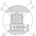
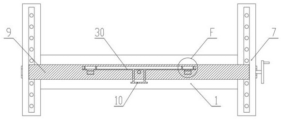
In order to achieve the purpose, the invention provides the following technical scheme: a self-limiting adjustment type lifting device for ophthalmic care, which can prevent arm shake, comprises a main frame body, wherein sliding frames are connected with two sides of the inner part of the lower end face of the main frame body, a screw rod is connected with the sliding frame on the part inside the main frame body, a rocking handle is fixedly connected with the right end of the screw rod, a fixing frame is fixedly connected with the lower end of the sliding frame, a pressing bolt is connected with one side surface of the fixing frame, one end of the pressing bolt is connected with a pressing block through a bearing, longitudinal rails are fixedly connected with two sides of the upper end face of the main frame body, limiting grooves are arranged on the inner bottom surface of the longitudinal rails, sliding beams are arranged on the longitudinal rails, the lower ends of two sides of the sliding beams are connected with the inner parts of the longitudinal rails through longitudinal sliding blocks, limiting balls are connected with the inner parts of the lower ends of the longitudinal blocks, limiting springs are connected with the upper ends of the limiting balls, a first damping cylinder is fixedly connected with the middle parts of the lower end faces of the sliding beams, a lifting shaft is connected in the first damping cylinder, a piston plate is connected at the lower end of the lifting shaft, an auxiliary adjusting spring is arranged on the side surface of the upper end of the lifting shaft, a transverse rail is connected at the upper end of the lifting shaft, lifting blocks are fixedly connected on two sides of the lower end surface of the transverse rail, a sliding plate is arranged in a sliding beam corresponding to the rear side of the lifting blocks, clamping blocks are connected on two sides of the front end surface of the sliding plate, a second reset spring is connected on two sides of the rear end surface of the sliding plate, a push block is connected at the middle part of the front end surface of the sliding plate through a shaft, a positioning rack is arranged in the front end of the transverse rail, a transverse sliding block is connected on the transverse rail in a sliding manner, a driving block is arranged in the transverse sliding block, a positioning rod is fixedly connected on the front end surface of the driving block, a first reset spring is connected on the rear end surface of the driving block, and a push rod is connected on the transverse sliding block at one end of the driving block, and a second damping cylinder is fixedly connected to the upper end face of the transverse sliding block, a rotating plate is connected to the inside of the second damping cylinder through a shaft, and a lifting block is fixedly connected to the upper end of the rotating plate shaft.
Preferably, a threaded hole is formed in the upper end of the sliding frame, the sliding frame is connected with the screw rod through threads, and the thread turning directions of the threaded holes in the sliding frame on the two sides inside the main frame body are opposite.
Preferably, the structural shape of the fixing frame is an inverted U-shaped structure, and a knob is arranged on one side of a compression bolt connected to the side surface of the fixing frame.
Preferably, oil is arranged inside the first damping cylinder, a piston plate inside the first damping cylinder is movably connected with the inner wall of the first damping cylinder in a sealing mode, and a circular through hole is formed in the piston plate.
Preferably, oil is arranged inside the second damping cylinder, and circular through holes are symmetrically formed in two sides of a rotating plate inside the second damping cylinder.
Preferably, a square groove is formed in the rear end face of the lifting block, and the size of the square groove in the lifting block is matched with that of the clamping block.
Preferably, the structure shape of the limiting groove is a spherical groove, the size of the limiting groove is matched with the limiting ball body, and the limiting ball body is movably connected with the longitudinal sliding block.
Preferably, the driving block is provided with a straight notch, one end of the push rod is connected with the straight notch arranged on the driving block through a shaft, and the included angle between the straight notch arranged on the driving block and the longitudinal plane is 45 degrees.
Compared with the prior art, the invention has the beneficial effects that: this can prevent that arm shake from spacing regulation formula ophthalmology nursing is with lifting device can be convenient for carry out all-round regulation to lifting the piece to can make medical personnel adjust it to comfortable arm lifting position, and can be convenient for fast and stable adjust each structure, thereby can make medical personnel timely treat the ophthalmology patient, and can be convenient for improve this ophthalmology nursing is with lifting device's installation suitability:
1. the self-limiting adjusting type lifting device for ophthalmic care, which can prevent arm shaking, can adjust the height and the angle of the lifting block in all directions, so that ophthalmic care medical personnel can adjust the lifting block to a comfortable arm lifting position, and the phenomenon that the medical personnel shake the treatment arm of a patient for a long time can be conveniently prevented;
2. the position of the lifting block can be quickly adjusted and automatically limited by pushing or pulling the sliding cross beam and pressing the push block and the push rod, and the lifting block and the arm can stably and synchronously rotate according to the requirement of the arm of the medical worker, so that the various structures can be conveniently and quickly and stably adjusted, and the medical worker can timely treat the ophthalmic patient;
3. the screw rod inside the main frame body is driven to rotate through rotating the rocking handle, so that the screw rod drives the sliding frame to move left and right in the main frame body through threads, and the threaded holes on the sliding frames on the two sides of the main frame body are opposite in threaded direction, so that the sliding frame can be simultaneously close to or far away from the main frame body, the lifting device can be installed on medical beds or medical chairs with different widths, and the installation applicability of the lifting device for the ophthalmic nursing is improved.
Drawings
FIG. 1 is a front perspective view of the present invention;
FIG. 2 is a schematic cross-sectional front view of the present invention;
FIG. 3 is an enlarged view of point A of FIG. 2 according to the present invention;
FIG. 4 is an enlarged view of point B of FIG. 2 according to the present invention;
FIG. 5 is an enlarged view of point C of FIG. 2 according to the present invention;
FIG. 6 is a schematic top view of a first cross-sectional structure of the present invention;
FIG. 7 is an enlarged view of point D in FIG. 6 according to the present invention;
FIG. 8 is a schematic diagram of a right-side cross-sectional structure of the present invention;
FIG. 9 is an enlarged view of point E in FIG. 8 according to the present invention;
FIG. 10 is a schematic top view of a second cross-sectional structure of the present invention;
FIG. 11 is an enlarged view of point F of FIG. 10 according to the present invention;
FIG. 12 is a schematic bottom view of the present invention.
In the figure: 1. a main frame body; 2. a carriage; 3. a fixing frame; 4. a hold-down bolt; 5. a compression block; 6. a rocking handle; 7. a longitudinal rail; 8. a first damping cylinder; 9. a sliding beam; 10. a push block; 11. a transverse rail; 12. a transverse slide block; 13. a second damping cylinder; 14. a lifting block; 15. a screw rod; 16. a lifting block; 17. a lifting shaft; 18. an auxiliary adjusting spring; 19. a piston plate; 20. a rotating plate; 21. a push rod; 22. a limiting spring; 23. a limiting ball body; 24. a longitudinal slide block; 25. a limiting groove; 26. positioning the rack; 27. a drive block; 28. positioning a rod; 29. a first return spring; 30. a sliding plate; 31. a clamping block; 32. a second return spring.
Detailed Description
The technical solutions in the embodiments of the present invention will be clearly and completely described below with reference to the drawings in the embodiments of the present invention, and it is obvious that the described embodiments are only a part of the embodiments of the present invention, and not all of the embodiments. All other embodiments, which can be derived by a person skilled in the art from the embodiments given herein without making any creative effort, shall fall within the protection scope of the present invention.
Referring to fig. 1-12, the present invention provides a technical solution: a self-limiting adjustment type lifting device for ophthalmologic nursing capable of preventing arm shaking comprises a main frame body 1, a sliding frame 2, a fixing frame 3, a pressing bolt 4, a pressing block 5, a rocking handle 6, a longitudinal rail 7, a first damping cylinder 8, a sliding beam 9, a push block 10, a transverse rail 11, a transverse sliding block 12, a second damping cylinder 13, a lifting block 14, a screw rod 15, a lifting block 16, a lifting shaft 17, an auxiliary adjusting spring 18, a piston plate 19, a rotating plate 20, a push rod 21, a limiting spring 22, a limiting ball 23, a longitudinal sliding block 24, a limiting groove 25, a positioning rack 26, a driving block 27, a positioning rod 28, a first reset spring 29, a sliding plate 30, a clamping block 31 and a second reset spring 32, wherein the sliding frame 2 is connected with the sliding frame 2 at two sides of the inner part of the main frame body 1, the screw rod 15 is connected with the sliding frame 2 at the inner part of the main frame body 1, and the rocking handle 6 is fixedly connected with the right end of the screw rod 15, the lower end of the sliding frame 2 is fixedly connected with a fixed frame 3, one side surface of the fixed frame 3 is connected with a compression bolt 4, one end of the compression bolt 4 is connected with a compression block 5 through a bearing, two sides of the upper end surface of the main frame body 1 are fixedly connected with longitudinal rails 7, the bottom surface of the inner part of each longitudinal rail 7 is provided with a limiting groove 25, the longitudinal rails 7 are provided with sliding beams 9, the lower ends of two sides of each sliding beam 9 are connected with the inner part of each longitudinal rail 7 through longitudinal sliding blocks 24, the lower ends of the longitudinal sliding blocks 24 are internally connected with limiting spheres 23, the upper ends of the limiting spheres 23 are connected with limiting springs 22, the middle part of the lower end surface of each sliding beam 9 is fixedly connected with a first damping cylinder 8, the first damping cylinder 8 is internally connected with a lifting shaft 17, the lower end of the lifting shaft 17 is connected with a piston plate 19, the side surface of the upper end of the lifting shaft 17 is provided with an auxiliary adjusting spring 18, and the upper end of the lifting shaft 17 is connected with a transverse rail 11, and both sides of the lower end surface of the transverse rail 11 are fixedly connected with lifting blocks 16, a sliding plate 30 is arranged in the sliding beam 9 corresponding to the rear side of the lifting block 16, and the two sides of the front end surface of the sliding plate 30 are connected with the clamping blocks 31, the two sides of the rear end surface of the sliding plate 30 are connected with the second return springs 32, the middle part of the front end surface of the sliding plate 30 is connected with the pushing block 10 through a shaft, a positioning rack 26 is arranged inside the front end of the transverse track 11, and the transverse rail 11 is connected with a transverse sliding block 12 in a sliding way, a driving block 27 is arranged inside the transverse sliding block 12, a positioning rod 28 is fixedly connected on the front end face of the driving block 27, a first return spring 29 is connected on the rear end face of the driving block 27, and a push rod 21 is connected on the transverse sliding block 12 at one end of the driving block 27, a second damping cylinder 13 is fixedly connected on the upper end surface of the transverse sliding block 12, and a rotating plate 20 is connected to the inside of the second damping cylinder 13 through a shaft, and a lifting block 14 is fixedly connected to the upper end of the shaft of the rotating plate 20.
The upper end of the sliding frame 2 is provided with a threaded hole, the sliding frame 2 is connected with the screw rod 15 through threads, the threaded hole threads on the sliding frame 2 on two sides inside the main frame body 1 are opposite in turning direction, the rocking handle 6 can be rotated conveniently, the rocking handle 6 drives the screw rod 15 inside the main frame body 1 to rotate, the screw rod 15 drives the sliding frame 2 to move left and right in the main frame body 1 through threads, the sliding frame 2 is opposite in turning direction through the threaded hole threads on the sliding frame 2 on two sides inside the main frame body 1, the sliding frame 2 is close to or away from the main frame body 1 simultaneously, the lifting device can be installed on the medical bed or the medical chair with different widths, and the installation applicability of the lifting device is improved.
The structural shape of fixed frame 3 sets up to the "U" shape structure of invering, and the clamp bolt 4 one side of connecting on the fixed frame 3 side is provided with the knob, can be convenient for set up to the "U" shape structure of invering through the structural shape of fixed frame 3 and make fixed frame 3 block of being convenient for at the side of the bed of doctorsing and nurses, and can be convenient for through rotating clamp bolt 4, clamp bolt 4 drives compact heap 5 under the effect of screw thread and presss from both sides tightly the side of the bed of doctorsing and nurses at fixed frame 3 internal motion, thereby can realize this ophthalmology nursing with lifting device's fast and stable fixed.
The inside fluid that is provided with of first damping cylinder 8, and the inside piston plate 19 of first damping cylinder 8 and the sealed swing joint of 8 inner walls of first damping cylinder, and be provided with circular through-hole on the piston plate 19, can be convenient for make piston plate 19 when first damping cylinder 8 up-and-down motion through the inside piston plate 19 of first damping cylinder 8 and the sealed swing joint of 8 inner walls of first damping cylinder, the fluid in the first damping cylinder 8 only can flow through the circular through-hole on the piston plate 19, thereby can be convenient for make lift axle 17 can be stable go up and down, and then make the height of lifting block 14 be convenient for adjust suitable position more.
The inside fluid that is provided with of second damping section of thick bamboo 13, and the inside rotor plate 20 bilateral symmetry of second damping section of thick bamboo 13 is provided with circular through-hole, can be convenient for be provided with circular through-hole through the inside rotor plate 20 bilateral symmetry of second damping section of thick bamboo 13 and make and lift the inside rotor plate 20 rotation of piece 14 when rotating, rotor plate 20 is when the rotation of second damping section of thick bamboo 13, its inside fluid can only pass through the circular through-hole that the rotor plate 20 bilateral symmetry set up, thereby make and lift piece 14 and can produce certain damping force when rotating, thereby can be convenient for the rotation that medical personnel's arm can be stable, and can prevent that medical personnel's arm from producing and rocking when nursing patient's eyes.
Be provided with square groove on the 16 rear end faces of elevator, and square groove size and fixture block 31 phase-match on the elevator 16, can be convenient for through the fixture block 31 block to the square groove who sets up on the 16 rear end faces of elevator, make the position of elevator 16 injectd motionlessly, and can be convenient for through pressing ejector pad 10 at the middle part of sliding beam 9 front end, make the square groove who sets up on fixture block 31 and the 16 rear end faces of elevator break away from mutually, thereby can be convenient for adjust the height of lifting block 14.
Spacing groove 25's structural shape is spherical groove, and spacing groove 25's size of a dimension and spacing spheroid 23 phase-match, and spacing spheroid 23 and vertical slider 24 swing joint, can be convenient for make spacing spheroid 23 block under spacing spring 22's elasticity effect in spacing groove 25 through spacing groove 25's size of a dimension and spacing spheroid 23 phase-match, thereby can carry out automatic spacing to sliding beam 9's position, and can be convenient for make when promoting or pulling sliding beam 9 through spacing spheroid 23 and vertical slider 24 swing joint, spacing spheroid 23 is to vertical slider 24 internal motion, thereby make and to carry out fore-and-aft regulation to sliding beam 9's position.
Be provided with the straight notch on the drive block 27, and push rod 21 one end is connected through the straight notch that the axle set up on axle and the drive block 27, and the straight notch that sets up on the drive block 27 is 45 with vertical planar contained angle, can be convenient for through pressing push rod 21, push rod 21 drives the straight notch intraoral motion that the axle of its one side set up on drive block 27, thereby make drive block 27 to horizontal slider 12 internal motion, and can be convenient for drive locating lever 28 and location rack 26 through the motion of drive block 27 and break away from, thereby can make horizontal slider 12 slide on horizontal track 11, in order to adjust the horizontal position of lifting block 14.
The working principle is as follows: when the supporting device for ophthalmic care needs to be installed, firstly, the position of the fixing frame 3 is adjusted according to the width of the installation position;
by rotating the rocking handle 6, the rocking handle 6 drives the screw rod 15 in the main frame body 1 to rotate, and the screw rod 15 drives the sliding frame 2 to slide in the main frame body 1 under the action of the threads;
when the fixing frame 3 is adjusted to a proper position, the fixing frame 3 is clamped on the mounting position, and the compression bolt 4 on one side of the fixing frame 3 is rotated, so that the compression bolt 4 drives the compression block 5 to fix the fixing frame 3;
when the front and back positions of the lifting block 14 need to be adjusted, the longitudinal slide blocks 24 on the lower sides of the two ends of the sliding beam 9 drive the limiting balls 23 in the sliding beam 9 to move by pushing or pulling the sliding beam 9;
the limiting ball body 23 moves in the longitudinal rail 7, so that the limiting ball body 23 enters the limiting grooves 25 at different positions in the longitudinal rail 7, and the front and rear positions of the lifting block 14 are adjusted and automatically limited;
when the height of the lifting block 14 needs to be adjusted, the push block 10 in the middle of the front end of the sliding beam 9 is pressed, so that the push block 10 drives the sliding plate 30 in the sliding beam 9 to move backwards;
the sliding plate 30 moves backwards to separate the clamping block 31 from the square groove on the lifting block 16, and the transverse rail 11 moves upwards under the action of the elastic force of the auxiliary adjusting spring 18;
when the transverse rail 11 is pressed downwards, the transverse rail 11 drives the lifting block 16 to move downwards, and when the lifting block 14 is adjusted to a proper position, the push block 10 is released;
under the action of the elastic force of the second return spring 32, the sliding plate 30 moves towards the front end, so that the fixture block 31 is clamped with the square groove on the lifting block 16 to limit the position of the lifting block 16;
when the horizontal position of the lifting block 14 needs to be adjusted, the push rod 21 on the horizontal sliding block 12 is pressed, and the push rod 21 drives a shaft on one side of the push rod to move in a straight notch arranged on the driving block 27;
the driving block 27 moves towards the inside of the transverse sliding block 12, and the driving block 27 moves to drive the positioning rod 28 to be separated from the positioning rack 26, so that the transverse sliding block 12 can slide on the transverse track 11, and the transverse position of the lifting block 14 can be adjusted;
when the transverse position of the lifting block 14 is adjusted to a proper position, the driving block 27 is reset under the action of the elastic force of the first return spring 29 by releasing the push rod 21;
the driving block 27 drives the positioning rod 28 to enter the positioning rack 26, so that the transverse position of the lifting block 14 is automatically limited;
after the lifting device is adjusted, the medical staff can lift the arms of the medical staff by preventing the arms from entering the grooves of the lifting block 14, so that the medical staff is prevented from shaking the treatment arms for a long time;
in the lifting process, the medical staff can rotate the arm according to the requirement, so as to drive the lifting block 14 to synchronously rotate on the transverse sliding block 12, so as to meet the operation requirement of the medical staff, and the content which is not described in detail in the specification belongs to the prior art which is well known by the professional in the field.
It is to be understood that the terms "central," "longitudinal," "lateral," "front," "rear," "left," "right," "vertical," "horizontal," "top," "bottom," "inner," "outer," and the like are used in the orientations and positional relationships indicated in the drawings for the purpose of convenience and simplicity of description, and do not indicate or imply that the referenced devices or components must be in a particular orientation, constructed and operated in a particular orientation, and are not to be considered limiting of the scope of the present invention.
Although embodiments of the present invention have been shown and described, it will be appreciated by those skilled in the art that changes, modifications, substitutions and alterations can be made in these embodiments without departing from the principles and spirit of the invention, the scope of which is defined in the appended claims and their equivalents.
Claims (8)
1. The utility model provides a can prevent arm shake from spacing regulation formula ophthalmology nursing with lifting device, includes main frame body (1), its characterized in that: the inner two sides of the lower end face of the main frame body (1) are connected with sliding frames (2), the sliding frames (2) are connected with screw rods (15) on the inner portion of the main frame body (1), the right ends of the screw rods (15) are fixedly connected with rocking handles (6), the lower end of each sliding frame (2) is fixedly connected with a fixing frame (3), one side surface of each fixing frame (3) is connected with a compression bolt (4), one end of each compression bolt (4) is connected with a compression block (5) through a bearing, two sides of the upper end face of the main frame body (1) are fixedly connected with longitudinal rails (7), a limiting groove (25) is formed in the inner bottom face of each longitudinal rail (7), a sliding cross beam (9) is arranged on each longitudinal rail (7), the lower ends of two sides of the sliding cross beam (9) are connected with the inner portion of each longitudinal rail (7) through longitudinal sliding blocks (24), and limiting balls (23) are connected to the lower ends of the longitudinal sliding blocks (24), the upper end of the limiting ball body (23) is connected with a limiting spring (22), the middle part of the lower end face of the sliding cross beam (9) is fixedly connected with a first damping cylinder (8), the inside of the first damping cylinder (8) is connected with a lifting shaft (17), the lower end of the lifting shaft (17) is connected with a piston plate (19), the side face of the upper end of the lifting shaft (17) is provided with an auxiliary adjusting spring (18), the upper end of the lifting shaft (17) is connected with a transverse track (11), the two sides of the lower end face of the transverse track (11) are fixedly connected with lifting blocks (16), the sliding cross beam (9) corresponding to the rear side of the lifting blocks (16) is internally provided with a sliding plate (30), the two sides of the front end face of the sliding plate (30) are connected with clamping blocks (31), the two sides of the rear end face of the sliding plate (30) are connected with second return springs (32), and the middle part of the front end face of the sliding plate (30) is connected with a push block (10) through a shaft, the utility model discloses a damping device, including horizontal track (11), fixed rack (26) are provided with to horizontal track (11) front end inside, and sliding connection has horizontal slider (12) on horizontal track (11), inside driving block (27) that is provided with of horizontal slider (12), and fixedly connected with locating lever (28) on driving block (27) front side end face, be connected with first reset spring (29) on driving block (27) rear side end face, and be connected with push rod (21) on horizontal slider (12) of driving block (27) one end, fixedly connected with second damping cylinder (13) on horizontal slider (12) up end, and inside through the hub connection of second damping cylinder (13) has rotor plate (20) to rotor plate (20) epaxial end fixedly connected with lifts piece (14).
2. The self-limiting adjustable ophthalmic care lifting device capable of preventing arm vibration of claim 1, wherein: the upper end of the sliding frame (2) is provided with a threaded hole, the sliding frame (2) is connected with the screw rod (15) through threads, and the thread turning directions of the threaded holes on the sliding frame (2) on the two sides inside the main frame body (1) are opposite.
3. The self-limiting adjustable ophthalmic care lifting device capable of preventing arm vibration of claim 1, wherein: the structure shape of the fixed frame (3) is set to be an inverted U-shaped structure, and one side of a compression bolt (4) connected to the side surface of the fixed frame (3) is provided with a knob.
4. The self-limiting adjustable ophthalmic care lifting device capable of preventing arm vibration of claim 1, wherein: oil liquid is arranged inside the first damping cylinder (8), a piston plate (19) inside the first damping cylinder (8) is movably connected with the inner wall of the first damping cylinder (8) in a sealing mode, and a circular through hole is formed in the piston plate (19).
5. The self-limiting adjustable ophthalmic care lifting device capable of preventing arm vibration of claim 1, wherein: oil liquid is arranged inside the second damping cylinder (13), and circular through holes are symmetrically formed in two sides of the rotating plate (20) inside the second damping cylinder (13).
6. The self-limiting adjustable ophthalmic care lifting device capable of preventing arm vibration of claim 1, wherein: the rear end face of the lifting block (16) is provided with a square groove, and the size of the square groove in the lifting block (16) is matched with the clamping block (31).
7. The self-limiting adjustable ophthalmic care lifting device capable of preventing arm vibration of claim 1, wherein: the structure shape of the limiting groove (25) is a spherical groove, the size of the limiting groove (25) is matched with that of the limiting ball body (23), and the limiting ball body (23) is movably connected with the longitudinal sliding block (24).
8. The self-limiting adjustable ophthalmic care lifting device capable of preventing arm vibration of claim 1, wherein: the driving block (27) is provided with a straight notch, one end of the push rod (21) is connected with the straight notch arranged on the driving block (27) through a shaft, and the included angle between the straight notch arranged on the driving block (27) and the longitudinal plane is 45 degrees.
Priority Applications (1)
| Application Number | Priority Date | Filing Date | Title |
|---|---|---|---|
| CN202110718456.1A CN113520626A (en) | 2021-06-28 | 2021-06-28 | Self-limiting adjusting type lifting device capable of preventing arm from shaking for ophthalmic nursing |
Applications Claiming Priority (1)
| Application Number | Priority Date | Filing Date | Title |
|---|---|---|---|
| CN202110718456.1A CN113520626A (en) | 2021-06-28 | 2021-06-28 | Self-limiting adjusting type lifting device capable of preventing arm from shaking for ophthalmic nursing |
Publications (1)
| Publication Number | Publication Date |
|---|---|
| CN113520626A true CN113520626A (en) | 2021-10-22 |
Family
ID=78096962
Family Applications (1)
| Application Number | Title | Priority Date | Filing Date |
|---|---|---|---|
| CN202110718456.1A Pending CN113520626A (en) | 2021-06-28 | 2021-06-28 | Self-limiting adjusting type lifting device capable of preventing arm from shaking for ophthalmic nursing |
Country Status (1)
| Country | Link |
|---|---|
| CN (1) | CN113520626A (en) |
Citations (10)
| Publication number | Priority date | Publication date | Assignee | Title |
|---|---|---|---|---|
| US20060186292A1 (en) * | 2004-12-09 | 2006-08-24 | Ian Rutherford | Device for supporting at least one arm of an operating person during a surgical operation |
| CN206852738U (en) * | 2017-01-20 | 2018-01-09 | 重庆三峡医药高等专科学校 | A kind of medical assisted care frame |
| CN110652364A (en) * | 2019-11-07 | 2020-01-07 | 吉林大学 | Neurosurgery operation arm support moving along with arm |
| CN210044141U (en) * | 2019-03-05 | 2020-02-11 | 张阳 | Arm supporting device for neurosurgery operation |
| CN211271239U (en) * | 2019-11-29 | 2020-08-18 | 耿庆森 | Multi-functional bracket is used in ophthalmic surgery |
| CN211433384U (en) * | 2019-11-07 | 2020-09-08 | 吉林大学 | Neurosurgery operation arm support moving along with arm |
| CN212281684U (en) * | 2019-11-18 | 2021-01-05 | 郭星冉 | Arm support frame for operation |
| CN112245208A (en) * | 2020-11-05 | 2021-01-22 | 黄长迎 | Lifting device for neurology examination |
| CN212490196U (en) * | 2020-02-05 | 2021-02-09 | 晁冰 | Special hand bracket of microsurgery |
| CN212913428U (en) * | 2020-03-31 | 2021-04-09 | 叶思勇 | Arm support frame for ophthalmological fundus laser |
-
2021
- 2021-06-28 CN CN202110718456.1A patent/CN113520626A/en active Pending
Patent Citations (10)
| Publication number | Priority date | Publication date | Assignee | Title |
|---|---|---|---|---|
| US20060186292A1 (en) * | 2004-12-09 | 2006-08-24 | Ian Rutherford | Device for supporting at least one arm of an operating person during a surgical operation |
| CN206852738U (en) * | 2017-01-20 | 2018-01-09 | 重庆三峡医药高等专科学校 | A kind of medical assisted care frame |
| CN210044141U (en) * | 2019-03-05 | 2020-02-11 | 张阳 | Arm supporting device for neurosurgery operation |
| CN110652364A (en) * | 2019-11-07 | 2020-01-07 | 吉林大学 | Neurosurgery operation arm support moving along with arm |
| CN211433384U (en) * | 2019-11-07 | 2020-09-08 | 吉林大学 | Neurosurgery operation arm support moving along with arm |
| CN212281684U (en) * | 2019-11-18 | 2021-01-05 | 郭星冉 | Arm support frame for operation |
| CN211271239U (en) * | 2019-11-29 | 2020-08-18 | 耿庆森 | Multi-functional bracket is used in ophthalmic surgery |
| CN212490196U (en) * | 2020-02-05 | 2021-02-09 | 晁冰 | Special hand bracket of microsurgery |
| CN212913428U (en) * | 2020-03-31 | 2021-04-09 | 叶思勇 | Arm support frame for ophthalmological fundus laser |
| CN112245208A (en) * | 2020-11-05 | 2021-01-22 | 黄长迎 | Lifting device for neurology examination |
Similar Documents
| Publication | Publication Date | Title |
|---|---|---|
| CN206453860U (en) | A kind of neurosurgical surgical bracket | |
| CN110025396B (en) | Retaining frame that animal doctor's treatment was used | |
| CN111803368A (en) | Traditional chinese medical science is recovered with multi-functional acupuncture device | |
| CN217510607U (en) | Head fixing device for emergency trauma surgery | |
| CN111330169A (en) | Neck fixing device for emergency department | |
| CN212308767U (en) | Medical care is with recovered back exercise equipment of shank fracture | |
| CN112315697B (en) | Upper limb fixing and supporting frame for hemodialysis nursing | |
| CN113520626A (en) | Self-limiting adjusting type lifting device capable of preventing arm from shaking for ophthalmic nursing | |
| CN210330849U (en) | Four-dimensional cervical vertebra traction bed | |
| CN210673714U (en) | Training device is resumeed in linkage of department of neurology's both legs | |
| CN215273817U (en) | Ophthalmic eye drop rack | |
| CN211934758U (en) | Ophthalmic surgery support frame | |
| CN111166639B (en) | Massager for nursing aged and humpback patients | |
| CN209574909U (en) | A kind of support frame of the cerebral surgery operation with fixed function | |
| CN210330984U (en) | PICC puts a tub rest stand | |
| CN214805522U (en) | Ultrasonic interventional therapy bracket | |
| CN211535413U (en) | Examination bed convenient for adjusting pregnant women | |
| CN219126407U (en) | Novel adjustable fixing device of brain angiography of department of neurology | |
| CN213994142U (en) | Rheumatoid arthritis exercise activity ware | |
| CN216535870U (en) | Supporting device for surgical nursing of liver and gall | |
| CN219230618U (en) | Massage rehabilitation device for rehabilitation department | |
| CN215584714U (en) | Gynecological examination operation table convenient to height-adjusting | |
| CN216148541U (en) | Chest compression device for department of respiration | |
| CN221617764U (en) | Multifunctional scoliosis correcting rocking bed | |
| CN220002204U (en) | Seedling inoculation operation panel |
Legal Events
| Date | Code | Title | Description |
|---|---|---|---|
| PB01 | Publication | ||
| PB01 | Publication | ||
| SE01 | Entry into force of request for substantive examination | ||
| SE01 | Entry into force of request for substantive examination |