CN113520439A - System for stationary digital chest tomosynthesis imaging and related method - Google Patents
System for stationary digital chest tomosynthesis imaging and related method Download PDFInfo
- Publication number
- CN113520439A CN113520439A CN202110783159.5A CN202110783159A CN113520439A CN 113520439 A CN113520439 A CN 113520439A CN 202110783159 A CN202110783159 A CN 202110783159A CN 113520439 A CN113520439 A CN 113520439A
- Authority
- CN
- China
- Prior art keywords
- ray
- source array
- ray source
- projection images
- image
- Prior art date
- Legal status (The legal status is an assumption and is not a legal conclusion. Google has not performed a legal analysis and makes no representation as to the accuracy of the status listed.)
- Granted
Links
- 238000000034 method Methods 0.000 title claims abstract description 56
- 238000003384 imaging method Methods 0.000 title abstract description 57
- 238000012544 monitoring process Methods 0.000 claims abstract description 14
- 230000005855 radiation Effects 0.000 claims description 19
- 238000005070 sampling Methods 0.000 claims description 19
- 230000000241 respiratory effect Effects 0.000 claims description 12
- 230000000747 cardiac effect Effects 0.000 claims description 6
- 239000011159 matrix material Substances 0.000 claims description 4
- 210000000038 chest Anatomy 0.000 description 19
- 230000033001 locomotion Effects 0.000 description 19
- 238000010586 diagram Methods 0.000 description 15
- 230000008569 process Effects 0.000 description 14
- 210000000481 breast Anatomy 0.000 description 12
- 230000006870 function Effects 0.000 description 9
- 238000013170 computed tomography imaging Methods 0.000 description 8
- OKTJSMMVPCPJKN-UHFFFAOYSA-N Carbon Chemical compound [C] OKTJSMMVPCPJKN-UHFFFAOYSA-N 0.000 description 6
- 206010058467 Lung neoplasm malignant Diseases 0.000 description 6
- 238000012937 correction Methods 0.000 description 6
- 201000005202 lung cancer Diseases 0.000 description 6
- 208000020816 lung neoplasm Diseases 0.000 description 6
- 210000001015 abdomen Anatomy 0.000 description 5
- 239000002041 carbon nanotube Substances 0.000 description 5
- 229910021393 carbon nanotube Inorganic materials 0.000 description 5
- 210000004072 lung Anatomy 0.000 description 5
- 230000029058 respiratory gaseous exchange Effects 0.000 description 5
- 238000002591 computed tomography Methods 0.000 description 4
- 238000003745 diagnosis Methods 0.000 description 4
- 238000010894 electron beam technology Methods 0.000 description 4
- 210000000214 mouth Anatomy 0.000 description 4
- 238000012545 processing Methods 0.000 description 4
- 238000003325 tomography Methods 0.000 description 4
- 230000001133 acceleration Effects 0.000 description 3
- 238000004458 analytical method Methods 0.000 description 3
- 210000003484 anatomy Anatomy 0.000 description 3
- 230000034994 death Effects 0.000 description 3
- 231100000517 death Toxicity 0.000 description 3
- 230000009977 dual effect Effects 0.000 description 3
- 230000007246 mechanism Effects 0.000 description 3
- SYHGEUNFJIGTRX-UHFFFAOYSA-N methylenedioxypyrovalerone Chemical compound C=1C=C2OCOC2=CC=1C(=O)C(CCC)N1CCCC1 SYHGEUNFJIGTRX-UHFFFAOYSA-N 0.000 description 3
- 206010006322 Breath holding Diseases 0.000 description 2
- 206010028980 Neoplasm Diseases 0.000 description 2
- 206010056342 Pulmonary mass Diseases 0.000 description 2
- 230000003213 activating effect Effects 0.000 description 2
- 238000013459 approach Methods 0.000 description 2
- 230000008901 benefit Effects 0.000 description 2
- 238000004891 communication Methods 0.000 description 2
- 238000013500 data storage Methods 0.000 description 2
- 238000001514 detection method Methods 0.000 description 2
- 230000004907 flux Effects 0.000 description 2
- 230000003902 lesion Effects 0.000 description 2
- 238000013507 mapping Methods 0.000 description 2
- 210000000115 thoracic cavity Anatomy 0.000 description 2
- 210000001519 tissue Anatomy 0.000 description 2
- WFKWXMTUELFFGS-UHFFFAOYSA-N tungsten Chemical compound [W] WFKWXMTUELFFGS-UHFFFAOYSA-N 0.000 description 2
- 229910052721 tungsten Inorganic materials 0.000 description 2
- 239000010937 tungsten Substances 0.000 description 2
- 230000000007 visual effect Effects 0.000 description 2
- 206010006187 Breast cancer Diseases 0.000 description 1
- 208000026310 Breast neoplasm Diseases 0.000 description 1
- RYGMFSIKBFXOCR-UHFFFAOYSA-N Copper Chemical compound [Cu] RYGMFSIKBFXOCR-UHFFFAOYSA-N 0.000 description 1
- 201000003883 Cystic fibrosis Diseases 0.000 description 1
- 206010061818 Disease progression Diseases 0.000 description 1
- 208000019693 Lung disease Diseases 0.000 description 1
- 238000007476 Maximum Likelihood Methods 0.000 description 1
- 208000000236 Prostatic Neoplasms Diseases 0.000 description 1
- 208000003386 Radiation-Induced Neoplasms Diseases 0.000 description 1
- 230000003187 abdominal effect Effects 0.000 description 1
- 238000003491 array Methods 0.000 description 1
- 230000009286 beneficial effect Effects 0.000 description 1
- 230000005540 biological transmission Effects 0.000 description 1
- 201000009267 bronchiectasis Diseases 0.000 description 1
- 201000011510 cancer Diseases 0.000 description 1
- 231100000504 carcinogenesis Toxicity 0.000 description 1
- 208000029742 colonic neoplasm Diseases 0.000 description 1
- 229910052802 copper Inorganic materials 0.000 description 1
- 239000010949 copper Substances 0.000 description 1
- 230000001934 delay Effects 0.000 description 1
- 238000013461 design Methods 0.000 description 1
- 201000010099 disease Diseases 0.000 description 1
- 230000005750 disease progression Effects 0.000 description 1
- 208000037265 diseases, disorders, signs and symptoms Diseases 0.000 description 1
- 230000002526 effect on cardiovascular system Effects 0.000 description 1
- 230000000694 effects Effects 0.000 description 1
- 238000005516 engineering process Methods 0.000 description 1
- 238000007687 exposure technique Methods 0.000 description 1
- 229910002804 graphite Inorganic materials 0.000 description 1
- 239000010439 graphite Substances 0.000 description 1
- 230000001678 irradiating effect Effects 0.000 description 1
- 210000005075 mammary gland Anatomy 0.000 description 1
- 239000003550 marker Substances 0.000 description 1
- 239000000463 material Substances 0.000 description 1
- 238000005259 measurement Methods 0.000 description 1
- 238000002844 melting Methods 0.000 description 1
- 230000008018 melting Effects 0.000 description 1
- 230000003287 optical effect Effects 0.000 description 1
- 210000002307 prostate Anatomy 0.000 description 1
- 210000001147 pulmonary artery Anatomy 0.000 description 1
- 238000002601 radiography Methods 0.000 description 1
- 230000009467 reduction Effects 0.000 description 1
- 238000011160 research Methods 0.000 description 1
- 238000012216 screening Methods 0.000 description 1
- 230000003068 static effect Effects 0.000 description 1
- 230000004083 survival effect Effects 0.000 description 1
- 230000002123 temporal effect Effects 0.000 description 1
- 230000002792 vascular Effects 0.000 description 1
Images


Classifications
-
- A—HUMAN NECESSITIES
- A61—MEDICAL OR VETERINARY SCIENCE; HYGIENE
- A61B—DIAGNOSIS; SURGERY; IDENTIFICATION
- A61B6/00—Apparatus or devices for radiation diagnosis; Apparatus or devices for radiation diagnosis combined with radiation therapy equipment
- A61B6/02—Arrangements for diagnosis sequentially in different planes; Stereoscopic radiation diagnosis
- A61B6/025—Tomosynthesis
-
- A—HUMAN NECESSITIES
- A61—MEDICAL OR VETERINARY SCIENCE; HYGIENE
- A61B—DIAGNOSIS; SURGERY; IDENTIFICATION
- A61B6/00—Apparatus or devices for radiation diagnosis; Apparatus or devices for radiation diagnosis combined with radiation therapy equipment
- A61B6/02—Arrangements for diagnosis sequentially in different planes; Stereoscopic radiation diagnosis
- A61B6/03—Computed tomography [CT]
- A61B6/037—Emission tomography
-
- A—HUMAN NECESSITIES
- A61—MEDICAL OR VETERINARY SCIENCE; HYGIENE
- A61B—DIAGNOSIS; SURGERY; IDENTIFICATION
- A61B6/00—Apparatus or devices for radiation diagnosis; Apparatus or devices for radiation diagnosis combined with radiation therapy equipment
- A61B6/06—Diaphragms
-
- A—HUMAN NECESSITIES
- A61—MEDICAL OR VETERINARY SCIENCE; HYGIENE
- A61B—DIAGNOSIS; SURGERY; IDENTIFICATION
- A61B6/00—Apparatus or devices for radiation diagnosis; Apparatus or devices for radiation diagnosis combined with radiation therapy equipment
- A61B6/40—Arrangements for generating radiation specially adapted for radiation diagnosis
- A61B6/4007—Arrangements for generating radiation specially adapted for radiation diagnosis characterised by using a plurality of source units
-
- A—HUMAN NECESSITIES
- A61—MEDICAL OR VETERINARY SCIENCE; HYGIENE
- A61B—DIAGNOSIS; SURGERY; IDENTIFICATION
- A61B6/00—Apparatus or devices for radiation diagnosis; Apparatus or devices for radiation diagnosis combined with radiation therapy equipment
- A61B6/42—Arrangements for detecting radiation specially adapted for radiation diagnosis
- A61B6/4266—Arrangements for detecting radiation specially adapted for radiation diagnosis characterised by using a plurality of detector units
-
- A—HUMAN NECESSITIES
- A61—MEDICAL OR VETERINARY SCIENCE; HYGIENE
- A61B—DIAGNOSIS; SURGERY; IDENTIFICATION
- A61B6/00—Apparatus or devices for radiation diagnosis; Apparatus or devices for radiation diagnosis combined with radiation therapy equipment
- A61B6/42—Arrangements for detecting radiation specially adapted for radiation diagnosis
- A61B6/4275—Arrangements for detecting radiation specially adapted for radiation diagnosis using a detector unit almost surrounding the patient, e.g. more than 180°
-
- A—HUMAN NECESSITIES
- A61—MEDICAL OR VETERINARY SCIENCE; HYGIENE
- A61B—DIAGNOSIS; SURGERY; IDENTIFICATION
- A61B6/00—Apparatus or devices for radiation diagnosis; Apparatus or devices for radiation diagnosis combined with radiation therapy equipment
- A61B6/48—Diagnostic techniques
- A61B6/482—Diagnostic techniques involving multiple energy imaging
-
- A—HUMAN NECESSITIES
- A61—MEDICAL OR VETERINARY SCIENCE; HYGIENE
- A61B—DIAGNOSIS; SURGERY; IDENTIFICATION
- A61B6/00—Apparatus or devices for radiation diagnosis; Apparatus or devices for radiation diagnosis combined with radiation therapy equipment
- A61B6/48—Diagnostic techniques
- A61B6/488—Diagnostic techniques involving pre-scan acquisition
-
- A—HUMAN NECESSITIES
- A61—MEDICAL OR VETERINARY SCIENCE; HYGIENE
- A61B—DIAGNOSIS; SURGERY; IDENTIFICATION
- A61B6/00—Apparatus or devices for radiation diagnosis; Apparatus or devices for radiation diagnosis combined with radiation therapy equipment
- A61B6/50—Apparatus or devices for radiation diagnosis; Apparatus or devices for radiation diagnosis combined with radiation therapy equipment specially adapted for specific body parts; specially adapted for specific clinical applications
- A61B6/502—Apparatus or devices for radiation diagnosis; Apparatus or devices for radiation diagnosis combined with radiation therapy equipment specially adapted for specific body parts; specially adapted for specific clinical applications for diagnosis of breast, i.e. mammography
-
- A—HUMAN NECESSITIES
- A61—MEDICAL OR VETERINARY SCIENCE; HYGIENE
- A61B—DIAGNOSIS; SURGERY; IDENTIFICATION
- A61B6/00—Apparatus or devices for radiation diagnosis; Apparatus or devices for radiation diagnosis combined with radiation therapy equipment
- A61B6/52—Devices using data or image processing specially adapted for radiation diagnosis
- A61B6/5205—Devices using data or image processing specially adapted for radiation diagnosis involving processing of raw data to produce diagnostic data
-
- A—HUMAN NECESSITIES
- A61—MEDICAL OR VETERINARY SCIENCE; HYGIENE
- A61B—DIAGNOSIS; SURGERY; IDENTIFICATION
- A61B6/00—Apparatus or devices for radiation diagnosis; Apparatus or devices for radiation diagnosis combined with radiation therapy equipment
- A61B6/52—Devices using data or image processing specially adapted for radiation diagnosis
- A61B6/5258—Devices using data or image processing specially adapted for radiation diagnosis involving detection or reduction of artifacts or noise
-
- A—HUMAN NECESSITIES
- A61—MEDICAL OR VETERINARY SCIENCE; HYGIENE
- A61B—DIAGNOSIS; SURGERY; IDENTIFICATION
- A61B6/00—Apparatus or devices for radiation diagnosis; Apparatus or devices for radiation diagnosis combined with radiation therapy equipment
- A61B6/54—Control of apparatus or devices for radiation diagnosis
- A61B6/541—Control of apparatus or devices for radiation diagnosis involving acquisition triggered by a physiological signal
-
- A—HUMAN NECESSITIES
- A61—MEDICAL OR VETERINARY SCIENCE; HYGIENE
- A61B—DIAGNOSIS; SURGERY; IDENTIFICATION
- A61B6/00—Apparatus or devices for radiation diagnosis; Apparatus or devices for radiation diagnosis combined with radiation therapy equipment
- A61B6/40—Arrangements for generating radiation specially adapted for radiation diagnosis
- A61B6/4064—Arrangements for generating radiation specially adapted for radiation diagnosis specially adapted for producing a particular type of beam
- A61B6/4085—Cone-beams
Landscapes
- Health & Medical Sciences (AREA)
- Life Sciences & Earth Sciences (AREA)
- Engineering & Computer Science (AREA)
- Medical Informatics (AREA)
- Biomedical Technology (AREA)
- Heart & Thoracic Surgery (AREA)
- High Energy & Nuclear Physics (AREA)
- Physics & Mathematics (AREA)
- Nuclear Medicine, Radiotherapy & Molecular Imaging (AREA)
- Optics & Photonics (AREA)
- Pathology (AREA)
- Radiology & Medical Imaging (AREA)
- Veterinary Medicine (AREA)
- Biophysics (AREA)
- Molecular Biology (AREA)
- Surgery (AREA)
- Animal Behavior & Ethology (AREA)
- General Health & Medical Sciences (AREA)
- Public Health (AREA)
- Physiology (AREA)
- Computer Vision & Pattern Recognition (AREA)
- Dentistry (AREA)
- Oral & Maxillofacial Surgery (AREA)
- Apparatus For Radiation Diagnosis (AREA)
Abstract
Systems and related methods for stationary digital chest tomosynthesis (s-DCT) imaging are disclosed. In some aspects, the system comprises: a stationary x-ray source array having an array of x-ray pixels configured to produce x-ray beams at different viewing angles relative to a stationary subject to be imaged; a stationary regional x-ray detector configured to record x-ray projection images of a subject; a physiological gating device for monitoring at least one physiological signal of a subject and defining a physiological phase and a time window based on the at least one physiological signal; and a computing platform configured to activate x-ray pixels based on the physiological phase and time window and upon receipt of the at least one physiological signal from a physiological gating device to synchronize x-ray exposure with the at least one physiological signal of the subject.
Description
The application is a divisional application of Chinese patent application with the application number of 201510916422.8, the application date of 2015, 10 and 20, and the invention name of 'system for stationary digital chest tomosynthesis imaging and related method'.
Cross Reference to Related Applications
This patent application claims priority to U.S. provisional application serial No. 62/066,091, filed on 20/10/2014, which is incorporated herein by reference in its entirety.
Benefits of government
The subject matter of the present disclosure was made with U.S. government support under approval number U54CA151652 granted by the national cancer institute. Accordingly, the U.S. government has certain rights in the subject matter of this disclosure.
Technical Field
The subject matter described herein relates to x-ray photography and x-ray tomography. More particularly, the subject matter disclosed herein relates to systems and related methods for stationary digital chest tomosynthesis (s-DCT) imaging.
Background
Lung cancer has been the leading cause of cancer death worldwide. Over 20 million new lung cancer cases are diagnosed each year in the united states, and the number of deaths in lung cancer exceeds the total number of deaths in breast, prostate, and colon cancers. Despite decades of research into diagnosis and treatment, survival rates remain low. Possible lung cancer screens include chest radiography (CXR) and Computed Tomography (CT). It is well known that CXR imaging does not perform well in the screening and identification of small cancer tumors due to small lesion size and poor conspicuity. CT imaging is currently the highest standard for imaging lung lesions because it can eliminate any overlapping anatomical structures and reveal hidden lung nodules. However, CT imaging incurs high costs and high radiation doses, which can lead to radiation-induced cancer. Therefore, CT imaging of lung cancer is not recommended for the general population.
Digital tomosynthesis is a three-dimensional (3D) imaging technique that provides reconstruction of slice images from a series of limited-angle projection images. Digital tomosynthesis improves the visibility of anatomical structures by reducing visual clutter from overlapping normal anatomical tissue. Some examples of current clinical tomosynthesis applications include chest, abdomen, musculoskeletal, and breast imaging. Digital Chest Tomosynthesis (DCT) imaging improves the visibility of anatomical structures such as pulmonary vessels, bronchial walls, small airways, vascular trees and bronchiectasis when compared to CXR imaging. DCT imaging shows the lungs in coronal planes with successive slices and gives a better overview of the bronchial tree when compared to conventional axial CT imaging. DCT imaging has better resolution in the image plane than CT imaging because it produces a coronal image and uses a higher resolution detector than CT imaging, whose spatial resolution is largely limited by the z-axis resolution of its detector. DCT imaging also enhances the detection of small lung nodules by reducing visual clutter from overlapping normal anatomical tissue. Also significant is that the radiation dose used in DCT imaging is between about 10-40 times lower than CT imaging, and its cost is only a fraction (i.e., about one tenth) of that of CT imaging.
Several commercial digital tomosynthesis systems exist including, for example, for breast imaging And
And for imaging the mammary gland
 And siemens MAMMOMAT
 Existing commercial tomosynthesis systems are similar in design in which projection images are acquired using an x-ray tube with a single x-ray generated focal spot by moving the x-ray source over a circular arc angle of about 10-50 degrees in relation to the subject to be imaged. Due to gantry rotation and mechanical instability, the effective focal spot size during image acquisition is larger than the static value that reduces image resolution. It is therefore desirable to provide a digital tomosynthesis imaging system that does not require mechanical motion of the x-ray source.
More importantly, mechanical movement of the heavy x-ray source gantry on a linear or circular arc trajectory requires acceleration and deceleration of the gantry. The instability associated with acceleration limits the maximum speed at which the gantry can move, and therefore essentially limits the speed of tomosynthesis image acquisition. Typically, the minimum scan time for existing mobile gantry chest tomosynthesis systems is above 5 seconds; typical adult respiratory cycles are three to five seconds, while children's respiratory cycles are one to three seconds. Therefore, conventional tomosynthesis imaging systems typically produce very poor image quality due to physiological motion of the patient. Existing mobile gantry chest tomosynthesis systems require breath-holding for imaging and are generally not suitable for pediatric imaging. For many lung disease patients and children, holding their breath for more than five seconds may be difficult. Accordingly, it is desirable to provide a system and associated method for stationary digital tomosynthesis imaging that makes patient motion insignificant.
Disclosure of Invention
Systems and related methods for stationary digital thoracic tomosynthesis (s-DCT) imaging are disclosed. In some aspects, the system and associated methods enable s-DCT imaging that drastically reduces motion blur caused by respiratory and cardiovascular motion, which may be used, for example, for applications other than chest tomography.
In some aspects, a system may include a stationary x-ray source array including an array of spatially distributed x-ray pixels configured to produce x-ray beams at different view angles relative to a stationary subject to be imaged; a stationary regional x-ray detector positioned substantially parallel to a plane of the x-ray source array and configured to record x-ray projection images of the subject from the different view angles for tomosynthesis reconstruction; a physiological gating apparatus for monitoring at least one physiological signal of a subject, the physiological gating apparatus defining a physiological phase and a time window based on the at least one physiological signal within which x-ray projection images of the subject from different view angles can be obtained; and a computing platform comprising a memory and at least one hardware processor, the computing platform configured to activate the x-ray pixels based on the physiological phase and time window and upon receiving at least one physiological signal from a physiological gating device to synchronize x-ray exposure with the at least one physiological signal of the subject.
In some aspects, a method may comprise: providing a stationary x-ray source array comprising an array of spatially distributed x-ray pixels configured to produce x-ray beams at different viewing angles with respect to a stationary subject to be imaged; and providing a stationary regional x-ray detector positioned substantially parallel to a plane of the x-ray source array and configured to record x-ray projection images of the subject from different view angles for tomosynthesis reconstruction; monitoring at least one physiological signal of a subject by a physiological gating device, the physiological gating device defining a physiological phase and a time window based on the at least one physiological signal, within which x-ray projection images of the subject from different view angles can be obtained; activating, by the computing platform, the x-ray pixels to synchronize the x-ray exposure with the at least one physiological signal of the subject when the at least one physiological signal is received; and recording x-ray projection images of the subject from different perspectives.
In some aspects, a method for generating one or more tomographic images of a human chest or torso can include: providing a stationary field emission x-ray source array having an array of x-ray generating focal spots spatially distributed with respect to an object to be imaged; irradiating the object with an x-ray beam produced by an x-ray generating focal spot; detecting a projection image of an object in five seconds or less; and reconstructing one or more tomographic images of the object based on the projection images of the object.
In some aspects, a method of producing one or more images of an object using at least one of a monochromatic and quasi-monochromatic x-ray beam is provided, which may include providing a field emission x-ray source having a spatially distributed focal spot with respect to an object to be imaged; illuminating the object with at least one of a monochromatic and quasi-monochromatic x-ray beam produced by an x-ray source to produce a projection image of the object; detecting a projection image of the object; and reconstructing one or more displayable images of the object based on the projection images of the object.
The subject matter disclosed herein may be implemented by a combination of software and hardware and/or firmware. For example, the subject matter described herein may be implemented by software executed by a processor. In one exemplary embodiment, the subject matter described herein may be implemented using a computer-readable medium having stored thereon computer-executable instructions that, when executed by a computer processor, control the computer to perform steps. Exemplary computer readable media suitable for implementing the subject matter disclosed herein include non-transitory devices such as disk storage devices, chip storage devices, programmable logic devices, and application specific integrated circuits. Furthermore, a computer-readable medium that implements the subject matter described herein may be located on a single device or computing platform or may be distributed across multiple devices or computing platforms.
While some aspects of the subject matter disclosed herein have been described above, and in whole or in part, by the presently disclosed subject matter, other aspects will become apparent as the description proceeds when taken in conjunction with the drawings described herein.
Drawings
The features and advantages of the present subject matter will be more readily understood from the following detailed description, which should be read in conjunction with the accompanying drawings, which are given by way of illustration only, and not by way of limitation, in which:
fig. 1 is a schematic diagram illustrating an exemplary stationary digital chest tomosynthesis (s-DCT) system including an array of linear multi-beam x-ray sources, in accordance with some aspects of the present subject matter;
FIG. 2A is a schematic diagram illustrating an exemplary x-ray source array including cathodes and cylindrical rotating anodes for use in s-DCT systems in accordance with some aspects of the present subject matter;
figure 2B is a detailed view illustrating a portion of the exemplary x-ray source array of figure 2A, in accordance with some aspects of the present subject matter;
3A-3C are each a schematic diagram illustrating a front view, a side view, and a front perspective view, respectively, of a multi-beam collimator and a linear x-ray source array for an s-DCT system in accordance with some aspects of the present subject matter;
FIG. 4 is a schematic diagram illustrating an exemplary position sensing device for an s-DCT system in accordance with some aspects of the present subject matter;
figure 5 is a schematic diagram illustrating an exemplary s-DCT system for a subject in a prone position, according to some aspects of the present subject matter;
figure 6 is a schematic diagram illustrating an exemplary s-DCT system for a subject in a standing position, in accordance with some aspects of the present subject matter;
FIG. 7 is a flow chart illustrating an exemplary process for acquiring a fast tomographic image using an s-DCT system in accordance with some aspects of the present subject matter;
FIG. 8 is a flow chart illustrating an exemplary process for acquiring respiratory gated tomographic images using an s-DCT system in accordance with some aspects of the present subject matter;
FIG. 9 is a flow chart illustrating an exemplary process for acquiring dual energy gated tomographic images using an s-DCT system in accordance with some aspects of the present subject matter;
FIG. 10 is a high-level block diagram illustrating an exemplary general-purpose computer system suitable for use in acquiring tomographic images using an s-DCT system in accordance with some aspects of the present subject matter;
fig. 11 is a flow chart illustrating an exemplary method for fixed digital tomosynthesis imaging according to some aspects of the present subject matter.
Detailed Description
The present subject matter relates to systems for stationary digital chest tomosynthesis (s-DCT) imaging and related methods. In one aspect, the present subject matter provides an s-DCT system having an x-ray source array and/or an area x-ray detector that enables stationary tomosynthesis imaging, i.e., imaging without moving the x-ray source or detector. Notably, the systems and related methods for s-DCT imaging as disclosed herein may be used for additional applications such as, for example, dental, breast, abdominal imaging. For example, the systems and related methods disclosed herein may be used for stationary x-ray digital breast tomosynthesis imaging as disclosed in U.S. patent No. 7,751,528 filed on 18/7/2008, the entire disclosure of which is incorporated herein by reference.
Conventional digital thoracic tomosynthesis (DCT) systems include an x-ray detector and an object that are both held stationary, while an x-ray source is mechanically moved and rotated along a linear trajectory to obtain different projection views of the object. In this manner, the physical limitations on the acceleration and deceleration of the x-ray source limit the scanning speed of such conventional DCT systems. For example, most existing DCT systems require about 10-15 seconds for scanning during which significant motion of the object (e.g., heart, lung, and body motion) and focal spot image blurring are likely to occur. Wherein any kind of movement or blurring of the focal spot image occurs during the scan, the image resolution and quality of the projected image may be degraded.
By contrast, fig. 1-11 provide an exemplary s-DCT system and associated method that utilizes an x-ray source array, such as, for example, a Carbon Nanotube (CNT) field emission x-ray source array, containing individual x-ray focal spots arranged in a one-dimensional or two-dimensional pattern. Such an x-ray source array is capable of fast acquisition (average scan time of about two to five seconds, with a fast frame detector the scan time can be one second or less) of all projection images required for tomosynthesis reconstruction without mechanical motion of the x-ray source, object (e.g., patient) or x-ray detector. This limits the possibility of significant patient motion occurring. Furthermore, the generation of a single x-ray at each focal spot may be physiologically gated to generate radiation only at a predetermined physiological phase (physiological phase), such that projection images are obtained at the same phase point within several respiratory cycles without the need for patient breath holding. This may significantly reduce or potentially eliminate any blurring of the focal spot between different projection images due to physiological motion. Thus, by eliminating mechanical motion, the exemplary s-DCT systems and associated methods disclosed herein are capable of acquiring higher quality and resolution tomographic images in a shorter scan time.
In addition, the s-DCT systems and associated methods disclosed herein provide low-dose imaging modalities. This advantageously allows multiple images of the patient to be acquired over a period of longitudinal monitoring of disease progression and/or treatment effect. Such ability is important for many diseases such as, for example, lung cancer and cystic fibrosis.
In addition, the s-DCT system and associated methods disclosed herein provide fast and gated imaging capabilities, enabling multi-phase tomosynthesis imaging of regions of interest (ROIs) such as, for example, the lungs and heart, over respiratory and cardiac cycles. In this way, temporal three-dimensional (3D) or four-dimensional (4D) dynamic images of the lungs and heart can be obtained at low dose, as compared to Computed Tomography (CT) imaging.
As used herein, unless otherwise specified, the terms "patient," "person," "subject," and "subject" are used generically and interchangeably to refer to the entity being scanned by the s-DCT system.
Referring now to FIG. 1, there is shown a schematic diagram of an exemplary s-DCT system, generally designated 100. In some scenarios, the s-DCT system 100 may be dedicated to imaging a patient's chest, while in other scenarios, the s-DCT system 100 may be adapted to image a patient's breast, mouth, abdomen, etc. The s-DCT system 100 can include an array of x-ray sources, generally designated 102, which can result in faster scan speeds without the mechanical motion present in conventional DCT systems. For example, the x-ray source array 102 may include a linear multi-beam x-ray source array including a plurality of independently programmable x-ray pixels arranged linearly. In other aspects, the x-ray source array may include a plurality of independently programmable x-ray pixels arranged in an arc, a perimeter of a circle, or a perimeter of a polygon, a two-dimensional matrix, or the like. Regardless, the x-ray pixels of the x-ray source array 102 can be uniformly spaced and/or angled for directing the x-ray beam 104 toward the patient P. In some aspects, the x-ray source array 102 can include 3 to 90 pixels. In some aspects, the patient P may be irradiated with at least one of a monochromatic x-ray beam and/or a quasi-monochromatic x-ray beam produced by an x-ray source.
Each pixel may include a cathode (e.g., a carbon nanotube field emission cathode, a thermionic cathode, or a photocathode) (see 210, fig. 2A), a gate electrode to extract electrons, and a set of electron focusing lenses (e.g., EinZel-type electrostatic focusing lenses) to focus the electrons to a small area or focal spot on a target (e.g., an anode). In some aspects, each anode may include a corresponding focal spot, generally designated 106. The x-ray focal spots 106 may be distributed in space such that the x-ray beams 104 emitted from the focal spots 106 may illuminate an ROI in an x-ray detector, generally designated 108, from different viewing angles θ 1, θ 2. In some aspects, the viewing angles θ 1, θ 2 may span an angular range of between approximately 10 degrees and 90 degrees, depending on a given source-image distance. For example, the viewing angles θ 1, θ 2 may each be about 16.91 degrees from horizontal. In another example, the viewing angles θ 1, θ 2 may be larger or smaller and/or may be two different angles. In some aspects, for example, the x-ray source array 102 may be linear and may include a central x-ray focal spot having an area greater than the remaining focal spots in the array. Such a configuration may allow for higher x-ray tube currents.
The x-ray detector 108 may be, for example, a high frame rate, digitized area x-ray detector configured to continuously capture the x-ray beam 104. In some scenarios, it may be desirable to configure the x-ray detector 108 with a fast frame rate. For example, the x-ray detector 108 may include a frame rate on the order of about 1-100 frames per second. In some aspects, it may also be desirable for the x-ray detector 108 to include a high spatial resolution, having a pixel size in a range of approximately, for example, between 10 x 10 microns and 200 x 200 microns, in order to detect projection images of the patient P.
In some aspects, the x-ray detector 108 may be positioned on an imaging plane that is substantially parallel to the x-ray source array 102. For example, the individual x-ray pixels, x-ray detector 108, and ROI may be arranged such that the generated projection images are detected by the x-ray detector. In order for the x-ray beam 104 to image a target region of the patient P while still falling within the ROI in the x-ray detector 108, it is desirable to position the target region of the patient P within the defined ROI. The x-ray beam 104 can then be directed at the ROI from several different angles. After the x-ray beam 104 passes through the patient P, it may be detected by an x-ray detector 108.
Referring now to fig. 2A-2B, schematic diagrams of an exemplary x-ray source array are shown, generally designated 200. The x-ray source array 200 may be configured to be implemented as part of an s-DCT system, such as the system 100 in fig. 1. In some aspects, x-ray source array 200 may be configured as an x-ray source array capable of producing a plurality of x-ray beams.
As shown in fig. 2A, an x-ray source array 200 may include an anode, generally designated 202. The anode 202 may be formed by providing the anode with a high melting temperature (e.g., tungsten), a high thermal capacity (e.g., tungsten)Graphite) and/or high thermal conductivity (e.g., copper). In some aspects, the anode 202 may be configured as a rotating anode structure adapted to increase thermal power. For example, the anode 202 may be configured to extend about a centerline C extending through the center of the anode structureLClockwise or counterclockwise. The arrow A provided in FIGS. 2A-2B shows the anode 202 about the centerline CLAlthough the anode 202 can rotate counterclockwise. In some aspects, the anode 202 may be rotated via a shaft.
In some aspects, x-ray source array 200 further may include a High Voltage (HV) anode contact, generally designated 204, and a HV power feed, generally designated 206. For example, as shown in fig. 2A, the HV anode contact 204 and the HV feed 206 are arranged on one end of a cylindrical anode structure. Optionally, the HV anode contact 204 and the HV feed 206 may be provided on the other end of the anode structure, or may be arranged on opposite ends, respectively. In some aspects, one or more focal tracks, generally designated 208, may be disposed around the outer perimeter of the anode 202. When more than one focal track 208 is disposed on the anode 202, the focal tracks 208 may be spaced apart from each other in parallel on the outer periphery of the anode 202. For example, fig. 2A shows three focal tracks 208 spaced approximately equidistant from each other on the outer periphery of the anode 202.
When the x-ray source array 200 includes a cathode, generally designated 210, an electron beam, generally designated 212, may be generated by the cathode 210 and directed toward a focal spot within and along the focal track 208. For example, the cathode 210 may include a CNT cathode positioned such that the electron beam 212 can strike a focal spot disposed within and along the focal track 208 of the anode 202 at an angle orthogonal to the outer perimeter of the anode 202. Thus, and as shown in FIG. 2B, when the anode 202 is about the centerline CLUpon rotation, the electron beam 212 may strike the anode surface at a focal point along the focal track 208, which may then produce an x-ray beam, generally designated 214, with the x-ray beam 214 directed away from the anode 202 at an approximately perpendicular angle relative to the direction of the electron beam 212. In this manner, the x-ray beam 214 mayTo be directed from the anode 202 to the ROI in the x-ray detector. Notably, the cathode 210 can be positioned such that the resulting x-ray beam can be directed toward the ROI, regardless of the position of the detector.
Referring now to fig. 3A-3C, a schematic diagram is provided illustrating one embodiment of a collimator assembly, generally designated 300, having three different views. 3A-3C and the accompanying description are for illustrative purposes only, and are not intended to limit in any way the type of collimator that may be used with the systems and associated methods described herein.
In some aspects, the collimator tray 310 may include a planar surface configured to be similar in size, shape, etc. to the x-ray source 302. For example, the collimator tray 310 may include a length and width similar to the length and width of the x-ray source array 302. In some aspects, a collimator tray 310 may be secured to the x-ray source 302. For example, collimator tray 310 may be secured to a bottom edge of x-ray source 302 along a lengthwise edge. In this manner, collimator tray 310 may be foldable or otherwise movable relative to x-ray source array 302 via a hinge, joint, spring, and/or any other movable attachment device relative to x-ray source array 302. In some aspects, the collimator tray 310 may include an array of openings, generally designated 312, that extend through the thickness of the tray 310. For example and as shown in fig. 3A-3C, there may be four openings 312 dispersed over the surface of the collimator tray 310. The openings 312 may be arranged in a pattern, such as, for example, a linear pattern, a circular pattern, a two-dimensional pattern, and the like. As shown in fig. 3A-3C, the openings 312 are provided as a two-dimensional pattern with two openings arranged towards a front edge of the collimator tray 310 and two openings arranged towards a rear edge of the collimator tray 310, wherein the rear edge is a tray edge to which the x-ray source array 302 may be attached or affixed to the tray 310. Alternatively, the openings 312 may be arranged in non-patterned, random, and/or other positions relative to one another. In some aspects, the opening 312 may be sized and shaped for this purpose. As shown in fig. 3A-3C, the openings 312 are arranged as four similarly sized, square-shaped openings, wherein each opening 312 collimates radiation generated from a respective focal spot 304 into a cone-shaped beam, generally designated 314, that substantially illuminates the detector 320. As a result, the opening 312 may be configured to confine the x-ray beam 306 to a particular ROI. Moving, adjusting, and/or changing the position of the opening 312 may be sufficient to constrain the x-ray beam 306 to a different ROI on the x-ray detector 320.
Referring now to fig. 4, there is shown a schematic diagram of an exemplary s-DCT system, generally designated 400. Like the s-DCT system 100 of FIG. 1, the s-DCT system 400 can be dedicated to imaging a patient's chest, while in other aspects the s-DCT system 100 can be adapted to imaging a patient's breast, mouth, abdomen, etc. In some aspects, the s-DCT system 400 can include an array of x-ray sources, generally designated 402, and an x-ray detector, generally designated 404. In some aspects, the x-ray source array 402 may include a linear multi-beam x-ray source array in which a plurality of pixels are arranged in a one-dimensional direction. Accordingly, pixels of the x-ray source array 402 may be arranged substantially parallel to an imaging surface of the x-ray detector 404 such that the x-ray detector may detect x-ray radiation generated by the x-ray source array 402. When the x-ray source array 402 is not mechanically connected or otherwise coupled to the x-ray detector 404 (e.g., via a robotic arm (not shown)), the s-DCT system 400 can use a position sensing device or other similar type of device to determine the precise position of the x-ray focal spot of the x-ray source 402 relative to the x-ray detector 404. In some aspects, and referring to FIG. 4, s-DCT system 400 includes one or more emitters, generally designated 406, used in conjunction with one or more receivers, generally designated 408, to determine the relative position of x-ray detector 404 with respect to x-ray source array 402 using geometric correction and/or other similar techniques.
In some aspects, the one or more emitters 406 include one or more signal emitters, fixed markers, or the like, disposed relative to the x-ray detector 404. For example, two signal emitters may be fixedly or removably disposed on opposite sides of x-ray detector 404. In this manner, the one or more emitters 406 may be fixedly positioned at a known distance from an x-ray focal spot disposed on the x-ray source 402. In some aspects, the one or more transmitters 406 may be configured to transmit signals, ultrasonic waves, etc., generally designated 410, which may be detected by one or more receivers 408 mounted on the x-ray source 402. The one or more receivers 408 can include one or more sensors, cameras, or the like, wherein each of the one or more receivers 408 is fixedly or removably disposed at a predetermined location on the x-ray source 402. For example, there may be three cameras 408: a first camera arranged on a longitudinally extending surface orthogonal to the surface on which the pixels are arranged at the center of the x-ray source array 402; a second camera disposed on a surface of the x-ray source array 402 that is orthogonal to both the surface on which the pixels are disposed and the surface on which the first camera is disposed; and a third camera disposed on a surface of the x-ray source array 402 opposite the surface on which the second camera is disposed. Other arrangements, numbers, etc. of one or more receptors 408 on the x-ray source array 402 are also contemplated.
Alternatively, one or more receivers 408 may be mounted on a collimator (not shown) and/or on any other structure that is not an x-ray source array but is configured to detect signals and/or waves 410 emitted by one or more emitters 406. For example, one or more emitters may be mounted on x-ray source array 402 proximate to one or more receivers configured to detect signals or light emitted by the one or more emitters and reflected by markers and/or structures (not shown) affixed to x-ray detector 404 and/or collimator (not shown). Regardless, the one or more receivers 408 may be configured to transmit the detected light, signals, etc. 410 to a computing platform for further processing and/or correction as will be described in further detail below.
Referring now to fig. 5, a schematic diagram is provided illustrating an exemplary s-DCT system, generally designated 500, for a patient P in a prone position. Although the s-DCT system 500 is shown for imaging a patient's chest, it will be apparent to those skilled in the art that the s-DCT system 500 may be used for imaging other parts of the patient P, e.g., breast, mouth, abdomen, etc. In some aspects, in comparison to the s-DCT system 600 of FIG. 6, which will be described in further detail, where the patient P is in an upright or standing position in the s-DCT system 600, the s-DCT system 500 can be configured such that the patient P lies in a prone position on the patient's bed.
In some aspects, the s-DCT system 500 includes an x-ray source array, generally designated 502, which can be a multi-beam, linear x-ray source array, similar to the x-ray source arrays described with respect to FIGS. 1 and 4. The x-ray source array 502 may include a plurality of focal spots, generally designated 504. For example, the plurality of focal spots 504 may be linearly distributed along a bottom surface of the x-ray source array 502, where the bottom surface is substantially parallel to the ground and/or an x-ray detector generally labeled 510. In some aspects, the x-ray focal spot 504 may be positioned to direct the x-ray beam 506 downward, toward, and/or through the ROI while the x-ray beam, generally designated 506, first passes through a collimator, generally designated 508, that enables it to be directed toward the ROI from several different angles. As previously described, with respect to the embodiments of the collimator in fig. 3A-3C, the collimator 508 may be attachable at least one edge of the x-ray source 502. In the view of fig. 5, in some aspects, collimator 508 may be attached substantially to the bottom surface of x-ray source array 502 via the top surface. However, the collimator 508 may be movable and/or tiltable at one edge relative to the x-ray source array 502.
Accordingly, the collimator 508 may constrain the x-ray beam 506 toward the ROI on the x-ray detector 510. In some versions, x-ray detector 510 is disposed below a patient bed 512 with patient P in a prone position. Accordingly, x-ray source array 502, patient P, and x-ray detector 510 may each be aligned such that x-ray beam 506 is detected by x-ray detector 510 after passing through patient P. x-ray detector 510 may be configured to collect and/or transmit all or at least a portion of detected x-ray beam 506. For example, x-ray detector 510 may be configured to collect and transmit detected x-ray beams 506 as x-ray signal data in an associated computing platform, generally designated 514. Computing platform 514 may include any platform configured to adjust data acquisition, perform image acquisition, correct geometry, sense position, reconstruct images, monitor a patient, and/or any other function associated with s-DCT imaging. Computing platform 514 may be a standalone tool, device, or software executing on a processor. For example, computing platform 514 may include electronic controllers. In some aspects, computing platform 514 may comprise a single node, or may be distributed across multiple computing platforms or nodes.
In some aspects, the computing platform 514 and/or SSM516 may be configured to operate the x-ray source array 502 up to about, for example, 130 kilovolts peak (kVp) and up to about 10-20 milliamps (mA) of tube current for each focal spot 504. However, a higher peak x-ray current of about 50-100 milliamps may be achieved by increasing the carbon nanotube area and the size of each focal spot 504. To minimize current fluctuations and delays and reduce pixel-to-pixel variations, computing platform 514 and/or SSM516 may incorporate an electrical compensation loop to adjust the gate voltage to maintain a constant preset emission current.
In some aspects, computing platform 514 and/or SSM516 may be configured to acquire a scout image of patient P once patient P is positioned. For example, computing platform 514 and/or SSM516 may be configured to acquire scout images of patient P in a prone position on bed 512. In some scenarios, it may be desirable to acquire scout images to ensure that the ROI is included in the field of view (FOV), to verify exposure techniques, to obtain a baseline, and so forth. For example, from the scout image, kVp, mAs, number of projection images, angular span, etc. for subsequent projection views may be determined. In this manner, the computing platform 514 and/or SSM516 may be able to determine the number of projection views, the coverage angle, the x-ray energy, and the image radiation dose prior to the tomosynthesis scan.
In some aspects, computing platform 514 and/or SSM516 may be configured to perform geometric corrections and/or position sensing of x-ray detector 510 relative to x-ray source array 502 when the two are not mechanically coupled or connected. For example, interface 518 of computing platform 514 and/or SSM516 may receive data and/or signals that may be used by correction software to determine the position of x-ray detector 510 relative to x-ray source array 502. For example, and referring back to FIG. 4, s-DCT system 400 may interface with a computing platform 514 or the like. In such an example, SSM516 (or the like) may include geometry correction software that is capable of utilizing an x-ray image of a correction marker disposed on the x-ray detection source relative to the x-ray source to determine the position of the x-ray detector relative to the x-ray source.
In some aspects, computing platform 514 and/or SSM516 may be configured to receive all or at least a portion of the x-ray signal data detected by x-ray detector 510 from x-ray detector 510 via interface 518 for image reconstruction functionality. For example, the computing platform 514 and/or the SSM516 may include Image Reconstruction Functionality (IRF) or other suitable functionality for reconstructing three-dimensional tomosynthesis slice images of the patient P. The image may be reconstructed by using a suitable technique, such as Filtered Back Projection (FBP), Simultaneous Iterative Reconstruction Technique (SIRT), or model-based iterative reconstruction (MBIR), to obtain a three-dimensional tomographic image of the patient P. For example, the computing platform 514 and/or SSM516 may include a tomosynthesis reconstruction software package that uses a variety of algorithms including shift-and-add, filtered backprojection, ordered subsets connected maximum likelihood (ordered subsets) and the like. In some aspects, computing platform 514 and/or SSM516 may be configured to acquire multiple projection images of patient P by simultaneously activating multiple x-ray pixels of x-ray source array 502 at a given time based on a multiplexed imaging scheme, and thereby synchronize the exposure of x-rays with the data acquisition by x-ray detector 510 as described above. In some aspects, the projection images may be de-multiplexed before the tomosynthesis reconstruction software reconstructs the tomographic image of the patient P using the plurality of projection images of the patient P from different perspectives.
In some aspects, computing platform 514 and/or SSM516 may be configured to monitor physiological signals of patient P and synchronize acquisition of projection images with physiological gating signals such that projection images are only detected by x-ray detector 510 upon receipt of signals from a Physiological Monitoring Sensor (PMS) attached to patient P, generally designated 522. As shown in fig. 5, PMS 522 is located on the chest of patient P. PMS 522 may be configured to monitor physiological signals (e.g., respiratory and/or cardiac signals) of patient P and may transmit these signals to computing platform 514 and/or SSM516 via interface 518. Upon receiving these signals, computing platform 514 and/or SSM516 may be configured to define a signal-based physiological phase and time window such that computing platform 514 and/or SSM516 may synchronize the acquisition of the projection images with the physiological gating signals. For example, for the respiration of the patient P, the time window may be configured to occur at the same phase point within several respiration cycles of the patient. Thus, x-ray radiation will only be generated within a defined time window of each breathing cycle. Since the images are obtained at this same phase point within the respiratory cycle of each patient P, it is less likely that dissimilar motion of the patient P will occur affecting image quality. The synchronization in this way enables the projection images to be acquired only within the time window of the physiological phase, which advantageously significantly reduces or eliminates any blurring between different projection images due to physiological motion of the patient, so that a complete tomosynthesis scan can be completed within either a single breathing cycle or a plurality of breathing cycles. Thus, physiological gating can produce superior image quality without increasing the dose of radiation.
Referring to fig. 6, a schematic diagram is provided illustrating an exemplary s-DCT system, generally designated 600, for a patient P in a standing position. Although the s-DCT system 600 is shown for imaging a patient's chest, it will be apparent to those skilled in the art that the s-DCT system 600 can be used for imaging other parts of the patient P, such as the breast, mouth, abdomen, etc. In some aspects, the s-DCT system 600 can be configured such that the patient P stands in an upright position relative to the ground.
Similar to s-DCT system 500, s-DCT system 600 can include similar features that have substantially similar uses. In particular, s-DCT system 600 includes an x-ray source array, generally designated 602, which can be a multi-beam, linear x-ray source array similar to that described with respect to FIGS. 1, 4, and 5. The x-ray source array 602 may include one or more focal spots, generally designated 604. For example, one focal spot 604 is disposed along a longitudinally extending right-facing surface of the x-ray source array 602, wherein the right-facing surface is substantially perpendicular to the ground and/or parallel to an x-ray detector, generally designated 610. In some aspects, the x-ray focal spot 604 may be positioned to direct the x-ray beam 606 to the right, toward, and/or through the ROI while the x-ray beam, generally designated 606, first passes through a collimator, generally designated 608, that enables it to be directed toward the ROI from several different angles. As previously described, collimator 608 may be attachable at least one edge of x-ray source 602, relative to the embodiments of collimator in fig. 3A-3C. In the view of fig. 6, in some aspects, collimator 608 may be substantially attached to a right-facing surface of x-ray source array 602 via a longitudinally extending left-facing surface. However, the collimator 608 may be movable and/or tiltable at one edge relative to the x-ray source array 602.
Accordingly, the collimator 608 may constrain the x-ray beam 606 toward an ROI on the x-ray detector 610. In some versions, x-ray detector 610 is disposed on a vertical plane substantially perpendicular to the ground and located behind patient P when patient P is in a standing position. For example, and as shown in fig. 6, x-ray detector 610 is disposed against the chest of patient P in a vertical plane that is substantially parallel to x-ray source array 602. Accordingly, x-ray source array 602, patient P, and x-ray detector 610 may each be aligned such that x-ray beam 606 is detected by x-ray detector 610 after passing through patient P.
In some aspects, computing platform 614 and/or SSM616 may include functionality to control image acquisition of x-ray source array 602 while synchronizing data acquisition by x-ray detector 610 such that one or more projection images are recorded with radiation originating from each focal spot 604 in x-ray source array 602. In some aspects, computing platform 614 and/or SSM616 may be configured to acquire a scout image of patient P once patient P is positioned. For example, computing platform 614 and/or SSM616 may be configured to acquire a scout image of patient P in a standing position. In this manner, computing platform 614 and/or SSM616 may be able to determine the number of projection views, coverage angles, x-ray energies, and image radiation doses prior to tomosynthesis scanning. In some aspects, computing platform 614 and/or SSM616 may be configured to perform geometric corrections and/or position sensing of x-ray detector 610 relative to x-ray source array 602 when the two are not mechanically coupled or connected. In some aspects, computing platform 614 and/or SSM616 may be configured to receive all or at least a portion of the x-ray signal data detected by x-ray detector 610 from x-ray detector 610 via interface 618 for image reconstruction functionality. In some aspects, computing platform 614 and/or SSM616 may be configured to monitor physiological signals of patient P and synchronize acquisition of projection images with physiological gating signals such that projection images are only detected by x-ray detector 610 once PMS, generally labeled 622, attached to patient P receives the signals. As shown in fig. 6, PMS 622 is located on one side of patient P. PMS 622 may be configured to monitor physiological signals (e.g., respiratory and/or cardiac signals) of patient P and may transmit these signals to computing platform 614 and/or SSM616 via interface 618.
Accordingly, computing platform 614 and/or SSM616 may be configured to have the same functionality as computing platform 514 and/or SSM516 shown in FIG. 5, but with patient P in a standing position in the s-DCT system. Additionally, computing platform 614 and/or SSM616 may nonetheless be further configured to reduce photon scattering by performing beam sampling.
In particular, in conventional x-ray imaging, it is known that detected x-ray photons are composed of primary beam photons (i.e., those photons that travel from the x-ray source to the x-ray detector without changing direction) and scattered photons (i.e., those photons that have undergone one or more scatterings by the object, thereby changing their direction). However, only the detected primary photons are useful for imaging, as scattered photons may increase noise and reduce image contrast and contrast-to-noise ratio. In chest imaging applications, in particular, it is known that the ratio of scattered photons to primary photons can vary from about 0.5 to 5 depending on the ROI and the size of the patient. Thus, it may be beneficial to remove and/or correct for scattered photons. To do this, a primary beam sampling apparatus (PSA), generally designated 624, may be implemented to estimate and subtract the scattered photons.
In some aspects, and referring to FIG. 6, PSA624 may be implemented in s-DCT system 600 and may be positioned between x-ray detector 610 and patient P. In some aspects, PSA624 may include an anti-scatter plate or grid, generally designated 626, configured with a substantially opaque and/or flat surface and arranged in alignment with x-ray source array 602 and x-ray detector 610 in a vertical plane substantially parallel to x-ray source array 602 and x-ray detector 610. For example, grid 626 may be arranged such that the right-facing surface is substantially adjacent to the back of patient P, such that patient P is sandwiched between x-ray detector 610 and grid 626. In some aspects, grid 626 is sized in relation to x-ray detector 610. For example, in fig. 6, grid 626 has a width that is less than the width of x-ray detector 610. Optionally, the size of grid 626 may be larger than or substantially similar to the size of x-ray detector 610. In some aspects, grid 626 is constructed of a material that allows transmission of x-ray beam 606. In other versions, grid 626 is configured with a two-dimensional matrix of openings, generally designated 628, running parallel and perpendicular to x-ray source array 602, that are configured to allow x-ray beam 606 to pass therethrough. The openings 628 may comprise various shapes and/or sizes, or may be uniform. For example, the opening 628 may comprise a circular opening having an open area that is about three percent (3%) or less of the target ROI. In this way, any extra dose associated with the PSA image is minimal.
Thus, x-ray photons detected by x-ray detector 610 at a location below opening 628 may correspond to an accurate measurement of a primary photon beam passing through patient P. For example, two sets of projection images using the same parameters may be acquired and provided to computing platform 614 and/or SSM616 via interface 618 for processing each set of projection images. In this example, a set of projection images may consist of one or more scans that include the PSA624, while a set of projection images may consist of one or more scans that do not include the PSA 624. From the sampling of the primary beams, scattered photon counts at these locations can be obtained from which the total scatter profile of the patient P (without the PSA624 present) can be accurately estimated by the computing platform 614 and/or SSM 616. The estimated scattered photon image may then be subtracted from the PSA 624-free image of the patient P to provide a scatter-corrected projection image of the patient P without PSA 624. Notably, alternate sampling of the scatter plot may be sufficient to estimate the total scatter plot, since the scatter image of the patient P is generally smooth depending on the distance scale between the openings 628. Scatter corrected projection images with reduced scattered photon noise may then be used for tomosynthesis reconstruction on computing platform 614 and/or SSM616 to obtain three-dimensional images with substantially improved image contrast and contrast to noise ratio.
In some aspects, the position of the PSA624 relative to the x-ray source array 602 and/or the x-ray detector 610 may be controlled by the computing platform 614 and/or the SSM616 via the interface 618. Accordingly, the grid 626 is configured to be movable relative to at least one direction by a slide or mechanism, generally designated 630. For example, the grid 626 is configured to be movable in a vertical direction as indicated by arrow B by movement of the grid 626 along the sliding mechanism 630. Grid 626 may also or alternatively be moved in a horizontal direction relative to the ground. In some aspects, a user may interact with computing platform 614 and/or SSM616 via interface 618 to control the position of PSA624 relative to the ROI. For example, a different target ROI may require vertical movement of grid 626. The PSA624 is also configured to be quickly inserted between and/or removed from between the patient P and the x-ray source array 602 via the slide 630. In some aspects, the sliding device 630 may include a mechanical mechanism that allows the grid 626 to slide along the length of the device. For example, a track, slot, or other suitable configuration may allow corresponding features on grid 626 to be controllably moved along the length of slide 630. Other techniques for moving grid 626 relative to x-ray source array 602 are also contemplated. Additionally, the PSA624, or any type of scatter reduction method, may be implemented in an s-DCT system in which the patient P is in a posture other than a standing posture (e.g., s-DCT500, FIG. 5).
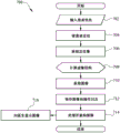
Referring to FIG. 7, a flow chart is provided illustrating an exemplary process, generally designated 700, for acquiring a fast tomographic image using an s-DCT system as described herein. The s-DCT system can include any of the systems described herein, including but not limited to s-DCT systems in which the patient is in a prone position, a standing position, and so forth. However, process 700 may also be implemented using a fixed digital tomosynthesis system for tomographic applications other than breast varieties.
In step 702, patient information may be entered into the exemplary computing platform via the interface. For example, patient information may be automatically transmitted to the computing platform and/or may be manually entered by a user.
In step 704, the patient may be positioned relative to the x-ray source array and/or the x-ray detector. For example, the patient may be positioned in a prone position (e.g., s-DCT system 500, FIG. 5) or an upright position (e.g., s-DCT system 600, FIG. 6). Optionally, the patient may also be positioned in a different posture (e.g., sitting).
In step 706, a scout image of the preliminary image can be acquired. For example, the computing platform may control acquisition of a scout image of the preliminary image to compute the image structure (e.g., in step 708).
In step 708, an image structure may be calculated based on the scout image of the preliminary image acquired in step 706. For example, the scout image of the preliminary image may be used to determine kVps, mAs, number of projected images, angular span, and so forth.
In step 710, a projection image may be acquired. For example, a computing platform (e.g., a controller) may activate individual pixels in an x-ray source array to illuminate a patient with an x-ray beam. The computing platform and/or controller may likewise control the x-ray detector to detect projection images of the patient to generate and thereby acquire projection images of the patient.
In step 712, the projection images and oplogs acquired in step 710 may be acquired and saved to a data store associated with the computing platform.
In step 714, the module associated with the computing platform may process the projection images to reconstruct a tomographic image. For example, IRF software implemented by the module and/or computing platform may be configured to access the stored projection images and/or the operational log(s) to reconstruct tomographic images of the patient based on the projection images of the patient. In some aspects, the tomographic image may be reconstructed by the IRF software using any suitable technique.
In step 716, the tomographic image may be selected for display on a display associated with the computing platform. For example, a doctor or other party of interest may access reconstructed tomographic images for a particular patient through a particular imaging session for analysis and/or diagnosis.
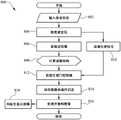
Referring to FIG. 8, a flow chart is provided illustrating an exemplary process, generally designated 800, for acquiring a fast tomographic image using a gated s-DCT system as described herein. The gated s-DCT system may comprise any system described herein, including but not limited to gated s-DCT systems in which the patient is in a prone position, standing position, and the like. However, the process 800 may also be implemented using gated stationary digital tomosynthesis systems for tomographic applications other than breast varieties.
In step 802, patient information may be entered into an exemplary computing platform via an interface. For example, patient information may be automatically transmitted to the computing platform and/or may be manually entered by a user.
In step 804, the patient may be positioned relative to the x-ray source array and/or the x-ray detector. For example, the patient may be positioned in a prone position (e.g., s-DCT system 500, FIG. 5) or an upright position (e.g., s-DCT system 600, FIG. 6). Optionally, the patient may also be positioned in a different posture (e.g., sitting).
In step 806, a scout image of the preliminary image can be acquired. For example, the computing platform may control acquisition of a scout image of the preliminary image to compute the image structure (e.g., in step 808).
In step 808, an image structure may be calculated based on the scout image of the preliminary image acquired in step 806. For example, the scout image of the preliminary image may be used to determine kVps, mAs, number of projected images, angular span, and so forth.
In step 810, a physiological signal may be monitored. In some aspects, after positioning the patient in step 804, a PMS can be attached to the patient to monitor physiological signals (e.g., respiratory and/or cardiac signals) of the patient. The PMS can communicate the signal to a computing platform, which can be configured to synchronize the physiological signal(s) with the acquisition of the projection images. In this way, projection images of the patient can be acquired only within the time window of the defined physiological phase.
In step 812, the physiologically gated image may be acquired by the computing platform while the PMS is being used. In some aspects, a computing platform (e.g., a controller) can activate individual pixels in the x-ray source array to illuminate the patient with the x-ray beam within the defined time window determined in step 810. Based on the information provided by the physiological gating signal, the time window may be defined such that images are only acquired at a particular phase point within the patient's physiological cycle. The computing platform and/or controller may likewise control the x-ray detector to detect projection images of the patient to generate and thereby obtain physiologically gated projection images of the patient.
In step 814, the physiologically gated projection images and oplogs acquired in step 812 may be acquired and saved to a data store associated with the computing platform.
In step 816, a module associated with the computing platform may process the physiologically gated projection images to reconstruct a tomographic image. For example, IRF software implemented by the module and/or computing platform may be configured to access the stored physiological gated projection images and/or the oplog(s) to reconstruct tomographic images of the patient based on the physiological gated projection images of the patient. In some aspects, the tomographic image may be reconstructed by the IRF software using any suitable technique.
In step 818, the tomographic image may optionally be displayed on a display associated with the computing platform. For example, a doctor or other party of interest may access reconstructed tomographic images for a particular patient through a particular imaging session for analysis and/or diagnosis.
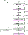
Referring to FIG. 9, a flow chart is provided illustrating an exemplary process, generally designated 900, for acquiring dual-energy or multi-energy tomographic images using a dual-energy s-DCT system as described herein. For example, in a dual energy tomography process, a complete set of two x-ray projection images may be acquired for each object being imaged. The first set may be acquired at x-ray energy 1 and the second set may be acquired at x-ray energy 2, where x-ray energy 1 is different from x-ray energy 2. In one approach, the two sets of x-ray images may be acquired at two different x-ray anode voltages. And then may be processed, reconstructed, and subtracted to enhance contrast for certain features. In another approach, two projection images may be taken at each view angle, one at x-ray energy 1 and the other at x-ray energy 2. As described in accordance with process 900, the dual-energy s-DCT system can include any of the systems described herein, including but not limited to dual-energy s-DCT systems in which the patient is in a prone position, a standing position, and so forth. However, the process 900 may also be implemented using a fixed digital tomosynthesis dual energy system for tomographic applications other than breast varieties.
In step 902, patient information may be entered into an exemplary computing platform via an interface. For example, patient information may be automatically transmitted to the computing platform and/or may be manually entered by a user.
In step 904, the patient may be positioned relative to the x-ray source array and/or the x-ray detector. For example, the patient may be positioned in a prone position (e.g., s-DCT system 500, FIG. 5) or an upright position (e.g., s-DCT system 600, FIG. 6). Optionally, the patient may also be positioned in a different posture (e.g., sitting).
In step 906, a scout image of the preliminary image can be obtained. For example, the computing platform may control acquisition of a scout image of the preliminary image to compute the image structure (e.g., in step 908).
In step 908, an image structure may be calculated based on the scout image of the preliminary image acquired in step 906. For example, the scout image of the preliminary image may be used to determine kVps, mAs, number of projected images, angular span, and so forth.
In step 910, a first set of High Energy (HE) images at a first voltage may be acquired by a computing platform. In some aspects, a computing platform (e.g., a controller) can activate individual pixels in an x-ray source array to illuminate a patient with an x-ray beam. The computing platform and/or controller may likewise control the x-ray detector to detect projection images of the patient to generate and thereby obtain HE projection images of the patient.
In step 912, a second set of Low Energy (LE) images at a second voltage may be acquired by the computing platform, wherein the second voltage is lower than the first voltage. In some aspects, a computing platform (e.g., a controller) can activate individual pixels in an x-ray source array to illuminate a patient with an x-ray beam. The computing platform and/or controller may likewise control the x-ray detector to detect projection images of the patient to generate and thereby obtain LE projection images of the patient.
In step 914, the HE projection image and the LE projection image acquired in steps 910-912 and the oplogs associated with each set of images may be acquired and saved to a data store associated with the computing platform.
In step 916, a module associated with the computing platform may process the HE projection images and the LE projection images to reconstruct the tomographic image. For example, IRF software implemented by the module and/or computing platform may be configured to access the stored HE projection images and LE projection images and/or the oplog to reconstruct tomographic images of the patient based on the HE projection images and LE projection images of the patient. In some aspects, the tomographic image may be reconstructed by the IRF software using any suitable technique.
In step 918, the tomographic image may optionally be displayed on a display associated with the computing platform. For example, a doctor or other party of interest may access reconstructed tomographic images for a particular patient through a particular imaging session for analysis and/or diagnosis.
Referring to FIG. 10, a high-level block diagram of exemplary components of a computing platform, generally designated 1002 and high-level block diagram, generally designated 1000, for performing the functions described herein is provided. As depicted in fig. 10, computing platform 1002 includes: a processor, generally designated 1004, a memory, generally designated 1006, communicatively connected via a system bus. In some aspects, the processor 1004 may include a microprocessor, a Central Processing Unit (CPU), or any other similar hardware based processing unit. In some aspects, the SSM, generally designated 1008, having functionality as discussed herein, may be stored in memory 1006, and memory 1006 may include Random Access Memory (RAM), Read Only Memory (ROM), optical read/write memory, cache memory, magnetic read/write memory, flash memory, or any other non-transitory computer-readable medium. In some embodiments, the processor 1004 and memory 1006 can be used to perform and manage the operations of the SSM 1008. Thus, when configured with SSM 1008, computing platform 1002 becomes a specialized computing platform that enhances the technical field of acquiring s-DCT images by eliminating the mechanical motion of conventional s-DCT systems. In particular, the cooperation between the computing platform 1002 and the s-DCT system (e.g., 500, FIG. 5) must be based on computer technology to overcome problems that arise particularly in the field of computer networks (i.e., acquiring s-DCT images with higher quality and resolution in shorter scan times).
Referring to fig. 11, a flow chart illustrating an exemplary method, generally designated 1100, for fixed digital tomography as described herein is provided.
In step 1102, a stationary x-ray source array including an array of x-ray pixels configured to produce a spatial distribution of x-ray beams at different viewing angles relative to a stationary subject to be imaged and a stationary regional x-ray detector positioned substantially parallel to a plane of the x-ray source array and configured to record x-ray projection images of the subject from different viewing angles for tomosynthesis reconstruction are provided.
In step 1104, a physiological gating device monitors at least one physiological signal of the subject, the physiological gating device defining a physiological phase and a time window based on the at least one physiological signal, within which x-ray projection images of the subject from different view angles can be acquired.
In step 1106, the computing platform activates the x-ray pixels when the at least one physiological signal is received to synchronize the x-ray exposure with the at least one physiological signal of the subject.
In step 1108, x-ray projection images of the subject from different view angles are recorded.
The present subject matter may be embodied in other forms without departing from the spirit or essential characteristics thereof. The embodiments described herein are therefore to be considered in all respects as illustrative and not restrictive. While the present subject matter has been described in terms of certain preferred embodiments, other embodiments that are apparent to those of ordinary skill in the art are also within the scope of the present subject matter.
Claims (20)
1. A method of generating a fast tomographic image of an object, the method comprising:
providing an x-ray source array configured to generate cone-beam x-ray radiation from an array of spatially distributed x-ray focal spots;
collimating the x-ray radiation from each x-ray focal spot of the x-ray source array to a region of interest in an area x-ray detector;
detecting and acquiring projection images of the object at the area x-ray detector, wherein during at least some projection images a primary beam sampling device is positioned between the x-ray source array and the area x-ray detector;
estimating and subtracting a scatter signal profile of the object from the projection image; and
a tomographic image is reconstructed based on the projection image with the reduced scatter signal.
2. The method of claim 1, further comprising arranging the area x-ray detector on a vertical plane substantially perpendicular to a ground surface and positioning the object between the x-ray source array and the area x-ray detector.
3. The method of claim 1, further comprising acquiring a scout image of the object and determining a number of projection views, a coverage angle, an x-ray energy, and an image radiation dose prior to detecting and acquiring the projection images of the object.
4. The method of claim 1, wherein detecting and acquiring the projection image of the object comprises:
monitoring a physiological gating signal of the subject using a physiological monitoring sensor attached to the subject; and
synchronizing acquisition of the projection images with the physiological gating signal.
5. The method of claim 4, further comprising detecting a projection image at the x-ray detector when a signal is received from the physiological monitoring sensor.
6. The method of claim 4, wherein the physiological gating signal comprises a respiratory or cardiac signal.
7. The method of claim 1, wherein estimating and subtracting the scatter signal profile of the object comprises:
positioning the primary beam sampling device between the x-ray source array and the object;
capturing a first one or more projection images of the object, wherein the first one or more projection images have reduced or eliminated x-ray photon scatter in one or more sampling regions;
removing the primary beam sampling device from between the x-ray source array and the object;
capturing a second one or more projection images of the object, wherein x-ray photon scatter of the second one or more projection images is not reduced;
obtaining a sample of the scatter signal profile of the object by comparing the first one or more projection images of the object with the second one or more projection images of the object; and
subtracting the scatter signal profile from the second one or more projection images to obtain the projection images with reduced scatter signal.
8. The method of claim 7, wherein the primary beam sampling device comprises an anti-scatter plate or grid having a substantially opaque or flat surface and arranged in alignment with the x-ray source array and the area x-ray detector on a vertical plane substantially parallel to the x-ray source array and the area x-ray detector; and is
Wherein the anti-scatter plate or the grid comprises a two-dimensional matrix of openings running parallel and perpendicular to the x-ray source array, the openings configured to allow x-ray photons to pass therethrough.
9. The method of claim 1, wherein the primary beam sampling device is configured to move horizontally or vertically relative to the ground.
10. A system for generating a fast tomographic image of an object, the system comprising:
an x-ray source array configured to generate a cone beam of x-ray radiation from an array of spatially distributed x-ray focal spots of the x-ray source array;
an area x-ray detector configured to detect x-ray radiation emitted from the x-ray source array;
a collimator located between the x-ray source array and a region of interest on the regional x-ray detector, the collimator configured to collimate x-ray radiation from each x-ray focal spot of the x-ray source array to the region of interest of the regional x-ray detector;
a primary beam sampling device, wherein the area x-ray detector is configured to detect and acquire projection images of the object, the primary beam sampling device being positioned between the x-ray source array and the area x-ray detector; and
a computing platform comprising one or more processors, the computing platform configured to:
estimating and subtracting a scatter signal profile of the object from the projection image; and
a tomographic image is reconstructed based on the projection image with the reduced scatter signal.
11. The system of claim 10, wherein the area x-ray detector is arranged on a vertical plane substantially perpendicular to a ground surface, and the system is configured such that the object is positioned between the x-ray source array and the area x-ray detector.
12. The system of claim 10, wherein the system is configured to capture a scout image of the object and determine the number of projection views, coverage angle, x-ray energy, and image radiation dose prior to detecting and acquiring the projection images of the object.
13. The system of claim 10, wherein the system is configured to:
monitoring a physiological gating signal of the subject using a physiological monitoring sensor attached to the subject; and
synchronizing acquisition of the projection images with the physiological gating signal.
14. The system of claim 13, wherein the detector is configured to detect projection images upon receiving a signal from the physiological monitoring sensor.
15. The system of claim 13, wherein the physiological gating signal comprises a respiratory or cardiac signal.
16. The system of claim 10, wherein the system is further configured to:
positioning the primary beam sampling device between the x-ray source array and the object;
capturing a first one or more projection images of the object, wherein the first one or more projection images have reduced or eliminated x-ray photon scatter in one or more sampling regions;
removing the primary beam sampling device from between the x-ray source array and the object;
capturing a second one or more projection images of the object, wherein x-ray photon scatter of the second one or more projection images is not reduced;
obtaining the scatter signal profile of the object by comparing the first one or more projection images of the object with the second one or more projection images of the object; and
subtracting the scatter signal profile from the second one or more projection images to obtain the projection images with reduced scatter signal.
17. The system of claim 16, wherein the primary beam sampling device comprises an anti-scatter plate or grid having a substantially opaque or flat surface and arranged in alignment with the x-ray source array and the area x-ray detector in a vertical plane substantially parallel to the x-ray source array and the area x-ray detector; and is
Wherein the anti-scatter plate or the grid comprises a two-dimensional matrix of openings running parallel and perpendicular to the x-ray source array, the openings configured to allow x-ray photons to pass therethrough.
18. The system of claim 10, wherein the primary beam sampling device is configured to move horizontally or vertically relative to the ground.
19. A method of producing one or more images of an object using at least one of a monochromatic x-ray beam and a quasi-monochromatic x-ray beam, the method comprising:
providing a field emission x-ray source having a spatially distributed focal spot with respect to an object to be imaged;
illuminating the object with at least one of a monochromatic x-ray beam and a quasi-monochromatic x-ray beam produced by the x-ray source to produce a projection image of the object;
detecting the projection image of the object; and
reconstructing one or more displayable images of the object based on the projection images of the object.
20. The method of claim 19, wherein illuminating the object further comprises illuminating the object from different perspectives.
Applications Claiming Priority (3)
| Application Number | Priority Date | Filing Date | Title |
|---|---|---|---|
| US201462066091P | 2014-10-20 | 2014-10-20 | |
| US62/066,091 | 2014-10-20 | ||
| CN201510916422.8A CN105615911B (en) | 2014-10-20 | 2015-10-20 | System for stationary digital chest tomosynthesis imaging and related method |
Related Parent Applications (1)
| Application Number | Title | Priority Date | Filing Date |
|---|---|---|---|
| CN201510916422.8A Division CN105615911B (en) | 2014-10-20 | 2015-10-20 | System for stationary digital chest tomosynthesis imaging and related method |
Publications (2)
| Publication Number | Publication Date |
|---|---|
| CN113520439A true CN113520439A (en) | 2021-10-22 |
| CN113520439B CN113520439B (en) | 2024-09-27 |
Family
ID=
Citations (5)
| Publication number | Priority date | Publication date | Assignee | Title |
|---|---|---|---|---|
| CN1768707A (en) * | 2004-09-30 | 2006-05-10 | 通用电气公司 | Method and system for multi-energy tomosynthesis |
| CN101158653A (en) * | 2007-11-16 | 2008-04-09 | 西北工业大学 | Diffuse transmission measuring and correcting method of cone-beam CT system |
| US20080240343A1 (en) * | 2007-03-30 | 2008-10-02 | General Electric Company | Portable digital tomosynthesis imaging system and method |
| CN101842052A (en) * | 2007-07-19 | 2010-09-22 | 北卡罗来纳大学查珀尔希尔分校 | Stationary x-ray digital breast tomosynthesis systems and correlation technique |
| CN103578082A (en) * | 2012-08-09 | 2014-02-12 | 江苏超惟科技发展有限公司 | Cone beam CT scatter correction method and system |
Patent Citations (5)
| Publication number | Priority date | Publication date | Assignee | Title |
|---|---|---|---|---|
| CN1768707A (en) * | 2004-09-30 | 2006-05-10 | 通用电气公司 | Method and system for multi-energy tomosynthesis |
| US20080240343A1 (en) * | 2007-03-30 | 2008-10-02 | General Electric Company | Portable digital tomosynthesis imaging system and method |
| CN101842052A (en) * | 2007-07-19 | 2010-09-22 | 北卡罗来纳大学查珀尔希尔分校 | Stationary x-ray digital breast tomosynthesis systems and correlation technique |
| CN101158653A (en) * | 2007-11-16 | 2008-04-09 | 西北工业大学 | Diffuse transmission measuring and correcting method of cone-beam CT system |
| CN103578082A (en) * | 2012-08-09 | 2014-02-12 | 江苏超惟科技发展有限公司 | Cone beam CT scatter correction method and system |
Also Published As
| Publication number | Publication date |
|---|---|
| US20210236067A1 (en) | 2021-08-05 |
| CN105615911A (en) | 2016-06-01 |
| CN105615911B (en) | 2021-07-27 |
| US10980494B2 (en) | 2021-04-20 |
| US20160106382A1 (en) | 2016-04-21 |
Similar Documents
| Publication | Publication Date | Title |
|---|---|---|
| CN105615911B (en) | System for stationary digital chest tomosynthesis imaging and related method | |
| US9907520B2 (en) | Digital tomosynthesis systems, methods, and computer readable media for intraoral dental tomosynthesis imaging | |
| US12016716B2 (en) | Stationary intraoral tomosynthesis imaging systems, methods, and computer readable media for three dimensional dental imaging | |
| Buzug | Computed tomography | |
| US8817947B2 (en) | Tomosynthesis imaging | |
| EP3420907A2 (en) | Variable distance imaging | |
| US7885378B2 (en) | Imaging system and related techniques | |
| JP6297504B2 (en) | Apparatus and method for digital radiography | |
| KR101477543B1 (en) | APPARATUS AND METHOD OF PHOTOGRAPHING USING X-ray | |
| JP4537129B2 (en) | System for scanning objects in tomosynthesis applications | |
| KR102677800B1 (en) | Multimodality dental X-ray imaging apparatus and method | |
| US11241207B2 (en) | Hybrid CT system with additional detectors in close proximity to the body | |
| US20230375484A1 (en) | Systems, devices, and methods for multisource volumetric spectral computed tomography | |
| US20200005496A1 (en) | Apparatus and method for scattered radiation correction | |
| JP2022545086A (en) | Detection of geometric calibration markers in spectral tomosynthesis systems | |
| KR101768520B1 (en) | A method of integrated operation of chest X-ray digital radiography and chest digital tomosynthesis | |
| US20050084147A1 (en) | Method and apparatus for image reconstruction with projection images acquired in a non-circular arc | |
| JP6466057B2 (en) | Medical diagnostic imaging equipment | |
| CN110881993B (en) | X-ray CT apparatus, medical image processing apparatus, and X-ray CT system | |
| US20180192966A1 (en) | Image acquisition device and method | |
| KR20160061555A (en) | Method and system of tomography for region-of-interest with arbitrary shape using dynamic collimation | |
| Goodsitt | The history of tomosynthesis | |
| JP2023156085A (en) | Nuclear medicine diagnosis device, nuclear medicine diagnosis method, and program | |
| JP2023074285A (en) | Medical image processing apparatus and x-ray diagnostic apparatus | |
| JP2006034519A (en) | Image photographing system |
Legal Events
| Date | Code | Title | Description |
|---|---|---|---|
| PB01 | Publication | ||
| PB01 | Publication | ||
| SE01 | Entry into force of request for substantive examination | ||
| SE01 | Entry into force of request for substantive examination |