CN1135115C - Disinfecting system - Google Patents
Disinfecting system Download PDFInfo
- Publication number
- CN1135115C CN1135115C CNB001086227A CN00108622A CN1135115C CN 1135115 C CN1135115 C CN 1135115C CN B001086227 A CNB001086227 A CN B001086227A CN 00108622 A CN00108622 A CN 00108622A CN 1135115 C CN1135115 C CN 1135115C
- Authority
- CN
- China
- Prior art keywords
- radiation
- decontamination system
- radiation source
- optical sensor
- measured
- Prior art date
- Legal status (The legal status is an assumption and is not a legal conclusion. Google has not performed a legal analysis and makes no representation as to the accuracy of the status listed.)
- Expired - Lifetime
Links
Images

Classifications
-
- A—HUMAN NECESSITIES
- A61—MEDICAL OR VETERINARY SCIENCE; HYGIENE
- A61L—METHODS OR APPARATUS FOR STERILISING MATERIALS OR OBJECTS IN GENERAL; DISINFECTION, STERILISATION OR DEODORISATION OF AIR; CHEMICAL ASPECTS OF BANDAGES, DRESSINGS, ABSORBENT PADS OR SURGICAL ARTICLES; MATERIALS FOR BANDAGES, DRESSINGS, ABSORBENT PADS OR SURGICAL ARTICLES
- A61L2/00—Methods or apparatus for disinfecting or sterilising materials or objects other than foodstuffs or contact lenses; Accessories therefor
-
- A—HUMAN NECESSITIES
- A61—MEDICAL OR VETERINARY SCIENCE; HYGIENE
- A61L—METHODS OR APPARATUS FOR STERILISING MATERIALS OR OBJECTS IN GENERAL; DISINFECTION, STERILISATION OR DEODORISATION OF AIR; CHEMICAL ASPECTS OF BANDAGES, DRESSINGS, ABSORBENT PADS OR SURGICAL ARTICLES; MATERIALS FOR BANDAGES, DRESSINGS, ABSORBENT PADS OR SURGICAL ARTICLES
- A61L12/00—Methods or apparatus for disinfecting or sterilising contact lenses; Accessories therefor
- A61L12/02—Methods or apparatus for disinfecting or sterilising contact lenses; Accessories therefor using physical phenomena, e.g. electricity, ultrasonics or ultrafiltration
- A61L12/06—Radiation, e.g. ultraviolet or microwaves
- A61L12/063—Ultraviolet radiation
-
- A—HUMAN NECESSITIES
- A61—MEDICAL OR VETERINARY SCIENCE; HYGIENE
- A61L—METHODS OR APPARATUS FOR STERILISING MATERIALS OR OBJECTS IN GENERAL; DISINFECTION, STERILISATION OR DEODORISATION OF AIR; CHEMICAL ASPECTS OF BANDAGES, DRESSINGS, ABSORBENT PADS OR SURGICAL ARTICLES; MATERIALS FOR BANDAGES, DRESSINGS, ABSORBENT PADS OR SURGICAL ARTICLES
- A61L2/00—Methods or apparatus for disinfecting or sterilising materials or objects other than foodstuffs or contact lenses; Accessories therefor
- A61L2/02—Methods or apparatus for disinfecting or sterilising materials or objects other than foodstuffs or contact lenses; Accessories therefor using physical phenomena
- A61L2/08—Radiation
- A61L2/10—Ultra-violet radiation
-
- B—PERFORMING OPERATIONS; TRANSPORTING
- B65—CONVEYING; PACKING; STORING; HANDLING THIN OR FILAMENTARY MATERIAL
- B65B—MACHINES, APPARATUS OR DEVICES FOR, OR METHODS OF, PACKAGING ARTICLES OR MATERIALS; UNPACKING
- B65B25/00—Packaging other articles presenting special problems
- B65B25/008—Packaging other articles presenting special problems packaging of contact lenses
Abstract
A sterilization system comprising: radiation source; optical and/or electrical sensors; and timing means; wherein the measurement of radiation by said optical sensor is substantially synchronized based on said timing means to the start and end of each pulse of radiation from said radiation source or to the start and end of the exposure of a product to said radiation source.
Description
Technical field
In a broad sense, the present invention relates to armarium be carried out disinfection by ultraviolet radiation, more particularly, the present invention relates to a kind of decontamination system, can measure the amount of radiation that produces by this decontamination system by this decontamination system, and the method for measuring and control the amount of radiation that produces by this decontamination system.
Background technology
Disinfecting of armarium, disinfecting in the especially commercial contact lens manufacture process relates generally to based on the temperature of a definite form and/or the disinfection technology of pressure.For example, usually at first form hydrophilic contact lens by monomer mixture being injected mould.Make monomer mixture polymerization (that is, lens solidify) then.After other selectable process step (for example quality examination), lens are placed in the container that fills solution, and with this seal of vessel.By this container is placed in the autoclave, with humidity, the temperature and pressure that increases, packaged lens were carried out disinfection with the time period that prolongs, be at least usually 15 minutes, more be typically 30 minutes.Though the processing procedure of this commercialization has been produced the contact lens of thorough disinfection, this batch-wise autoclave sterilization step is time-consuming, costliness and inefficiency.
European patent application No.0222309A1 discloses a kind of processing method of using ozone, in the production installation process packaging material is carried out disinfection in the method.This method comprises following process: Oxygen Flow is transported to ozone chamber, is produced ozone, packing container is put into clean room, ozone is transported to clean room and uses filtrated air the ozone that comes out from clean room is purified by oxygen in ozone chamber.This method requires one scheduled time of ozone contact packing material after the filtrated air purifying step.This method can be used as sterilization or a kind of replacement of chemical reagent disinfectant of vapours sterilization, application of electromagnetic radiation.
U.S. Patent No. 5,618,492 disclose a kind of method that is used for producing in sealed container at continuous flow procedure aseptic contact lens, wherein in successive lens packages process, contact lens is immersed in the solution that contains ozone in the container, and then lens and container carried out ultraviolet radiation with cracking ozone.This method is to contact lens and sterilizing containers.
U.S. Pat 4,464,336 have instructed application to send ultraviolet flash lamp comes disinfectant method, and this lamp produces a large amount of instantaneous output, and this output can make the microorganism that comprises aspergillus niger lose activity.
U.S. US5,034,235 and US4,871, near 559 that disclose using visible light and the visible frequency the strong and intermittent pulse light pulse that the persistent period is very short is brought the lip-deep microorganism that makes at food product and is lost activity, and proposes this method and can be used in food products in packing, armarium and the packing.
U.S. Pat 5,786,598 disclose the design that the application flashing light system carries out disinfection to the contact lens in the preservation solution in the container, yet, determine that condition realizes sterilization, there is not example to illustrate how sterilization realizes yet.
U.S. Pat 4,629,896 (for example disclose the monitoring ultraviolet light source, the device of intensity a kind of water sterilizer), the ultraviolet radiation of detection is arranged in this device and this radiation is converted to the optical detection unit of the signal of telecommunication so that can monitor radiant intensity, and, turn off this lamp when this intensity drops to certain level when following.
WO97/43915 discloses apply pulse light loses activity the microorganism in the contact lens container.Further, it also discloses a kind of method, and this method comprises: receive a part of pulsed light, generation corresponding to the output signal of the pulsed light of this reception and the level whether definite pulsed light enough reaches the deactivated regulation of microorganism that makes in presumptive area.WO97/43915 discloses and has used light filter to can both measure the amount of spectrum of flash of light in the various spectral regions or the flux that glistens at every turn.The possible component list of this equipment is very long, and these parts can be incorporated in this device of measurement, but does not describe the embodiment or the example of this equipment.WO97/43915 proposes to use the energy in the pulse of ultraviolet calorimeter measuring light, and claims that it is to derive from international standard; Yet the ultraviolet calorimeter only has linear response to certain strength, specific wavelength and the certain pulses width of light, only can make these specific parameters meet international standard thus.Outside these special parameters, the ultraviolet calorimeter generally has nonlinear response, and it is not the graduated structure that meets international standard.In addition, being not suitable for using the ultraviolet calorimeter demarcates optical detector and makes it meet international standard.The ultraviolet calorimeter only provides the single measurement value of gross energy in the ultraviolet frequencies scope, and any spectral information is not provided.The measurement result that it provided is a kind of non-standard, relative output that obtains with the spatial filtering coefficient based on pulsed light energy, responsiveness that multiply by detector and the passband that multiply by light filter, and this light filter only offers calorimeter with radiation value.In addition, because the calorimeter pick off is a kind of heat sensor, therefore it must have minimum 10 seconds quiescent time between pulse.If the ultraviolet calorimeter is used to provide instantaneous and on-line monitoring, not only inefficiency but also slow of apply pulse light disinfectant sterilization method then, it is very undesirable.
People still need a kind of time efficiency high, continuous embedded and decontamination system that comprise monitoring and control system cheaply, with a kind of especially sterilization method of curable product of product that is used for, it can be used on the production line, and can measure and control radiation and all be sterilized to guarantee every product.
Summary of the invention
The invention provides a kind of decontamination system, this decontamination system comprises: radiation source, the monitoring system that comprises pick off and a timing means, wherein on described timing means basis by said pick off to the measurement of energy basic and following synchronously: be exposed to beginning and end in the said radiation source from the beginning of the pulses of radiation of said radiation source and end or with product.
The present invention further provides the method for the energy of a kind of measurement in decontamination system, wherein said decontamination system comprises radiation source, comprises the monitoring system and the timing means of pick off that this method comprises following step:
Make by said pick off the measurement basic synchronization of energy in the beginning and the end that are exposed to from the beginning of the pulses of radiation of said radiation source and end or with product in the said radiation source based on said timing means.
The present invention further provides a kind of method of monitoring the energy of decontamination system, wherein said system comprises radiation source, comprises monitoring system and a timing means of pick off that this method comprises following step:
Make by said pick off the measurement basic synchronization of energy in the beginning and the end that are exposed to from the beginning of the pulses of radiation of said radiation source and end or with product in the said radiation source based on said timing means.
Preferred sensor is that a kind of optical sensor or electric transducer or both have.Optical sensor is measured the radiation that is produced by radiation source.The voltage and/or the electric current in electric transducer measuring radiation source.Comparative optimization be that every kind of decontamination system or monitoring system all have at least one pick off, be preferably an optical pickocff, more preferably every kind of decontamination system or monitoring system have at least one optical pickocff and at least one electric transducer.
The present invention further provides a kind of monitoring system that is used for radiation source, preferably be used for the disinfectant monitoring system, this monitoring system comprises pick off and timing means.In one embodiment, the invention provides a kind of monitoring system that comprises one or more optical sensors, this optical sensor comprises integrating sphere or cosine receptor (cosine receptor), photoconduction and spectroradiometer, and it has or is not used in the radiating timing means that measurement is produced by radiation source.In another embodiment as an alternative, the invention provides a kind of monitoring system, it comprises one or more electric transducers, and this electric transducer comprises the voltage and/or the current monitor of the electric energy that is used to produce radiating radiation source.
Decontamination system of the present invention and method comprise radiation source so that product is carried out disinfection, comparative optimization be that medical equipment is carried out disinfection.This decontamination system and method can be used in the suffered radiation of measurement products.Decontamination system as described herein and method also are well suited for being used for online production, and the accurately suffered radiation of measurement products can the disinfectant radiation dose to guarantee that every product receives.
When this pick off is optical pickocff, this decontamination system and method can be further used for measuring radiation on a plurality of positions in the swept area of radiation source, and provide a detailed two dimension or three-dimensional radiological to obtain the spatial characteristics figure of radiation source itself.In this occupation mode, this decontamination system is as autoemission source mapped system.This figure can be used in and guarantees that a radiation source and another radiation source are consistent, to guarantee sterilization dose concordance in production process.
Description of drawings
Accompanying drawing 1 is the FBD of decontamination system of the present invention.
Accompanying drawing 2 is depicted as an embodiment of decontamination system of the present invention.
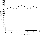
Accompanying drawing 3 is depicted as the radiation spectroscopy scheme of single radiation source.
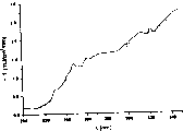
Accompanying drawing 4 be depicted as when flash lamp when being new and identical lamp in spectroradiometric measurement result through the lamp after 2600 flashes of light.
Specific embodiments
The term of Ying Yonging " aseptic " and " sterilization " here means and makes organism irreproducible.
If do not specify in addition, term " radiation source " refers to one or more radiation sources.
Term " ultraviolet radiation " means the wavelength that has between 200nm and 400nm or the radiation of a plurality of wavelength.
Preferably this decontamination system is used for curable product, preferably the contact lens in sealed container or packing.Decontamination system comprises a radiation source, and this radiation source can be the radiation source of any type, comprises continuous radiation source and impulse radiation source.Preferred radiation source is impulse radiation source (a for example flash lamp), and this impulse radiation source is a kind of radiation source that has very high intensity at short notice.Preferred pulsed light system is made by PurePulse Technologies, further describes referring to WO97-43915,5,034 235,5,786,598,5,768,853,4,871,559 and 4,464,336 (Hiramoto), all these is incorporated into own forces in this as a reference.The U.S. Patent application that preferred radiation source is applied for simultaneously people such as Brown Skrobot in decontamination system (it is entitled as " Method of Sterilization ", VTN-388) in, with way of reference with this application in conjunction with in the present invention.At present, comparative optimization be with pulsing (also can be called flicker) wavelength between 240-280nm, every pulse energy surpasses 18mJ/cm
2Ultraviolet radiation carry out disinfection to all surface of armarium, preferably send wavelength between 240-280nm, every pulse energy surpasses 30mJ/cm
2Ultraviolet radiation carry out disinfection to all surface of armarium.Preferred medical equipment is a contact lens, comparative optimization be that this contact lens is in sealed container or packing.Following description abutment lens packages; Yet, might or not be placed on medical equipment, other commodity or product in container or the packing and can substitute hereinafter contact lens package in describing yet.
The radiation of every pulse may be from one or more radiation sources or light source.(term light and radiation here can be used with exchanging).If radiation is from a more than radiation source, preferably radiation source sends pulse at the same time or substantially simultaneously, promptly in 25 microseconds, more preferably in 5 microseconds, most preferably in 1 microsecond.
Decontamination system further comprises a monitoring system.Monitoring system preferably includes pick off.This pick off can be that one or more optical pickocffs or electric transducer or both have.Comprise at least one optical sensor in preferred embodiments, more preferably comprise two optical sensors.
Preferably this optical sensor comprises the device that is used to gather radiating device and measuring radiation.Harvester can be a photoconduction, such as being liquid filling photoconduction or optical fibers, anti-refracting telescope, light guide, input slit (input slit), ultraviolet lenses, integrating sphere (integrating sphere), cosine receptor or thick iron or aforementioned listed combination.More preferably integrating sphere and cosine receptor.Integrating sphere is the most desirable.Usually integrating sphere can provide maximum visual field gathering radiation, and durable.By comparison, silicon fiber is not fine, because it suffers solarization easily, if promptly it is directly exposed to that it can lose its transmittability after after a while in the radiation.The integrating sphere that comprises many attrition resistant reflecting surfaces is gathered at least a portion radiation, and decay or amplification radiant intensity are transported to the measuring radiation device through photoconduction (preferred light guide fiber) with radiation then.As interchangeable another kind of mode be, the device of measuring radiation can be incorporated into to be gathered in the radiating device or opposite, but gather radiating device size in order to limit, this gathers radiating device preferably near radiation source, preferably have at present a segregation apparatus that is used for measuring radiation, and the device of measuring radiation is positioned at away from the radiation source place.It is very important that radiating device size is gathered in restriction, because the object of any close radiation source all may stop some radiation (can not reach product if stop these radiation), this is undesirable.Gather radiating device is transferred to the radiation of being gathered measuring radiation through illuminator, optical fiber, light guide, ultraviolet lenses etc. device, yet, more preferably use optical fiber, because with between the device of gathering radiating device and measuring radiation, require the method for fixed alignment to compare, its on locate mode relatively flexibly.
Integrating sphere is a kind of empty ball, and the internal coat at ball usually has the white diffuse material with fixed spectral reflectance factor.Integrating sphere has an inlet at least.Comparative optimization be that integrating sphere has two or more inlets.The number of inlet is reasonable to be that number with light source is complementary; Therefore, preferably have two inlets for current preferred decontamination system.It just can be positioned at any position as long as integrating sphere can receive part light at least; Yet the more desirable position of integrating sphere is between the light source but do not stop that light directly is radiated on the packing and the position parallel with the packing that is exposed.In this preferred positions, inlet more preferably is positioned at 30 ° to 60 ° at mid point from the packing that is exposed, more preferably 40 ° to 50 °, the most preferably on 45 ° the integrating sphere.In these preferred positions, incide the solid angle and the radiation source crossover of the light cone shape of each inlet.The geometry of this inlet or a plurality of inlets is used for determining being sent to the emittance of every area of packing.
Can be applied in ligh trap, outlet or Lycoperdon polymorphum Vitt reflector passage in the integrating sphere needs of radiation of decaying or double with the device that satisfies measuring radiation.Comparative optimization be that integrating sphere should send the enough energy of measuring radiation device to, so that energy is near the saturation irradiation amount of measuring radiation device in each pulse, thereby increases signal to noise ratio.Thereby the reflection coefficient of integrating sphere material has the amplification coefficient that certain feature can the accurate Calculation spheroid and keeps the trace ability (traceability) of NIST.In addition, comparative optimization is that the reflection coefficient of integrating sphere is consistent as much as possible in the whole radiation spectrum zone that will measure, so that be complementary with the response to the suitable gain control in whole zone of the device of measuring radiation.In other words, integrating sphere more preferably transmits the radiation by the basic equal percentage of all wavelengths of the measurement device of measuring radiation.The device of measuring radiation will be provided than the light of the much more equal percentage that is provided by for example light filter integrating sphere on certain wave-length coverage.Preferred integrating sphere collection is by the radiation of all wavelengths of radiation source generation.
The device of preferred measuring radiation can be measured total amount of radiation and in the amount of radiation of specific wavelength or wave-length coverage.The preferred a kind of spectrometer of the device of measuring radiation.Comparative optimization be that the input of spectrometer is the input of propagating optical fiber.Preferred spectrometer comprises optics dispersive element and photo-detector.As long as the optics dispersive element is separated into spectral components with radiation, it can be transmission or reflection.The example that can be applied in the optics dispersive element in the spectrometer comprises diffraction grating (flicker echelon, holographic grating, the ion(ic) etching grating), diffraction optical element (lens, window, mirror), binary optical elements (lens, window, mirror), light filter and mirror (holographic, dichroic, the arrowband, (cut-on) of cutting, (cut-off) that ends, film type, ultraviolet, dielectric, luminous, the cutting diamond-type), lens and window and prism, and groove (glass, plastics, lithographic printing, little lithographic printing, radial, duplicate), optical fiber be (glass, liquid, the drift diffusion, plastics), as long as it is just passable that it can be separated into radiation monochromatic radiation or spectral components, more preferably it is separated into spectral components.Preferred optics dispersive element is the diffraction grating reflector.Preferred diffraction grating reflector is a kind of holographic grating or ruling grating.More preferred spectrometer comprises propagates optical fiber input and diffraction grating reflector.Comparative optimization be that the optics dispersive element focuses on the photo-detector.
Photo-detector can be the photo-detector of any kind, as long as it can count to the number that appears at photon in a certain definite wave-length coverage or some wavelength, for example, it can be made up of photo-multiplier, photodiode and light cell in charge-coupled device (CCD) array.Preferred photo-detector is a photodetector array, more preferred photo-detector is a photodiode array, most preferably metal-oxide semiconductor (MOS) (MOS) linear transducer is such as the HamamatsuS3901-256Q photodiode array in the small-sized spectrometer of Zeiss MMS.The photodiode that any number can be arranged in array for example is at least 32 diodes, and 128 or more photodiode are more preferably arranged, and preferable is that 256 or more photodiode are arranged.In the most desirable spectrometer, on a monolithic, in an array 256 photodiodes are arranged.Grating is separated into the spectral components that is radiated on the photodiode array with radiation, the photon number of this photodiode statistics in the wave-length coverage that photo-detector is provided with.Extend to radiosusceptibility at least under the spectral response that preferred sensor has and be in the UV-C zone of 20mA/W (for example 200nm).The photodetector array of comparative optimization be spaced apart 60 microns or littler, preferable is between 20 to 60 microns.Preferably use the calibration of second order polynomial fit equation for pick off X-axis (wavelength) at interval.Comparative optimization be that the wavelength resolution of the photo-detector in spectroradiometer is less than 10nm, preferably less than 3nm, more preferably less than 1nm.Preferred as described spectroradiometer can produce the spectral irradiance table as the function of wavelength.
The device of measuring radiation can be single or the photo-detector of lesser amt, that is, less than 32 or less than 10 or even less than 3 photo-detectors, these photo-detectors are radiosensitive to narrower wave-length coverage.Photo-detector can be the radiosensitive photo-detector to specific wavelength.This is particularly suitable for producing the radiation source of the wavelength of limited range, for example laser.
Preferred spectrometer is to the wavelength sensitive between 185nm and 900nm.Yet, can use spectrometer with bigger or less photodetector array, it is for the bigger or less total scope of the wavelength in whole wave-length coverage and/or bigger or less incremental range sensitivity.Selection is to the spectrometer of the wavelength sensitive of needs monitoring.Current, preferred spectrometer minimum degree is to 200 to 400nm, more preferably to 200 to 300nm, the most preferably to 240 to 280nm wavelength sensitive, because the radiation of these wavelength having the greatest impact to microorganism.
Comparative optimization be to use wavelength and the radiosusceptibility that spectrometer is calibrated in the NIST source respectively; A source has known irradiation radiant intensity output, and another source has known spectral signal output.After using the spectral sensitivity and radiant sensitivity demarcation of NIST source to spectrometer, spectrometer becomes a spectroradiometer.If you are using, in calibration process, also should consider the gain or the attenuation quotient of integrating sphere.Calibration process is that the initial data from spectrometer (it is by every) is become with (mJ/cm
2)/nm is the standard radiation reading (be also referred to as radiation and divide luminous flux) of every wavelength of unit.Preferably, the circuit that will comprise analog-digital converter and relevant software driver (it allows to carry out communication with computer) joins in the spectrometer with stores it or uses measurement result and control decontamination system.
The monitoring system of decontamination system further comprises timing means.Timing means makes optical sensor only substantially only measure radiation from radiation source at each pulses of radiation in the persistent period or for the continuous radiation source in packing is exposed to time in the radiation of radiation source.For each embodiment in these embodiments, preferred acquisition and measuring radiation are in packing is exposed to the time of basic 100% in the radiation.For impulse radiation source, measure and gather every single pulses of radiation individually.Preferably make radiating collection and/or measurement and radiation send to packing and go up synchronously, especially for discrete radiating system, otherwise optical sensor is quit work preventing that dark current from making pick off saturated between pulse, and cause wrong actinometry.If packing receives a plurality of pulses to realize sterilization, then only when being radiated on the packing, the radiation source transmission gathers and/or measuring radiation, rather than between pulse during in, being sent to radiation amount on the packing is to measure like this: hold in the long or all wavelengths scope of standing wave one each is exposed to packing measuring radiation in the radiation, then the amount of radiation that records is added up.For example, in this embodiment preferred, pulses of radiation continue about 500 microseconds, so spectrometer approximately is activated 600 microseconds (before the pulse approximately during the 20-50 microsecond, approximately 50-80 microsecond end pulse after).The buffering of 20-80 microsecond has been guaranteed to gather and the radiation amount of measurement in pulse process.Total buffering of each pulse is preferably above 50 microseconds but less than 100 milliseconds.Optional but preferably, before measuring, in 100 milliseconds, from optical sensor, cut off the dark current radiation from the radiation in source.In addition, also be comparative optimization be, in carrying and measuring, measure and gather background radiation from the short time before any radiation in source, and from measured from subtracting background radiation the total amount radiation in source.Comparative optimization be, by on the same pulse duration or in continuous radiation, sending on the packing but radiation source does not produce the radiating optical sensor that starts simultaneously measures background radiation.After the total amount radiation of having measured from radiation source, subtracting background radiation from the total amount radiation, net radiation just can be compared with the standard amount of radiation or the needed radiation dose of sterilizing.
Timing means is controlled when optical sensor collection and measuring radiation.Timing means can be machinery or electricity or both combinations.Timing means can be can be by the intervalometer that starts optical sensor or the clock of following some incident, maybe will pack moving in the chamber of the sterilization dose that moves into receiver radiation such as: the instruction of excited radiation source, from the response of the radiation source that will excite, as long as these incidents provide time enough to make optical sensor respond this incident to prepare the whole radiation dose of measuring radiation to product, and allow any buffer time, i.e. a kind of incident before sending radiation by radiation source.Timing means is not from the radiation detection of the radiation source that is used for sterilization wrap (device), because the required response time of optical sensor will produce the measured value less than all direct radiation sterilisation radiation on the packaging.Timing means can be mechanical, electricity or optical dc-dc converter or control stick (lever), its can will pack shift-in receive in the radiating chamber of sterilization dose before, in this process or preferably, be activated thereafter, and its can be selectively in the radiating chamber that will pack shift-in reception sterilization dose before, in this process or thereafter it is stopped.Moving of packing can start transducer or control stick, and this transducer or control stick can make radiate source radiation carry out radiation simultaneously and optical sensor is measured, and transducer stops when removing packing, and radiation source and optical sensor are all quit work.Replacedly, if radiation source is successive, when packing is put into or when the target area is removed described dc-dc converter will only make optical sensor start or stop work, in this target area packing is exposed to radiation from radiation source.Replacedly, transducer or control stick, the preferred electron door can start single intervalometer for radiation source and/or optical sensor, so that start optical sensor measuring radiation source radiation radiation one known time, any buffered pulse.Preferred intervalometer is a solid-state electronic formula timer.
Preferred decontamination system also comprises a computer.In preferred embodiments, timing means is incorporated into sync cap that computer is connected in.Timing means and computerized optimization are not only controlled optical sensor but also control radiation source, so as to connect optical sensor and in the radiation source time-continuing process measuring radiation amount, optical sensor is stopped.The pulses of radiation persistent period is known, and intervalometer starts optical sensor and quits work and is based on the known pulse duration.In preferred decontamination system, computer starting radiation source activation sequence, and operational light pick off synchronously simultaneously.When computer sends the radiation source activation instruction, such as the LAMPFIRE instruction, produce a signal of telecommunication, and computer is waited for the response of LAMP-FIRING with the activating radiation source.When radiation source receives command signal, activate an inner activation sequence, begin to activate, and activation is through the signal in LAMP-FIRING electronic signal activating radiation source.When the synchronous circuit in the sync cap computer recognized the LAMP-FIRING signal, it started an intervalometer.Radiation source requires a known time quantum or a delay to prepare a pulse.When intervalometer indication synchronous circuit produces a signal is given spectrometer, and this signal starts spectrometer when radiation source begins, and intervalometer also sends a signal so that spectrometer stops when end-of-pulsing.Owing to require real-time response fast, preferably the application hardware instead of software realizes these functions.Preferably the circuit light of synchronous circuit and radiation source is isolated, and shields electromagnetic interference or noise from radiation source preferably.Signal is not preferably directly connected from these devices that radiation source passes to sync cap, but transmit information through a smooth division board, it generally terminates in the signal of telecommunication the right both sides of solid-state light signal generation transmitter/receiver, do not have electric spiking can pass this smooth division board, so just avoided permanent and expensive damage a system or two systems.
Therefore in the present embodiment, pulse can not produce at once, begins between the radiation for some time at LAMP-FIRING signal and radiation source.In this period that can not act on, it is accurate as much as possible with the measurement of guaranteeing spectrometer preferably to produce one or more steps.The first step is removed (outage) all electric charges on spectrometer before opening the optical gate of spectrometer.By making removing in time of the dark current on the photodiode several milliseconds in actual as much as possible flash of light, more desirable preferably less than 200 milliseconds less than 10 milliseconds, make actinometry error minimum from the dark current accumulation.Second step with the identical time interval measurement background radiation of flash duration of gathering and measuring background radiation.Then this measured value is deducted the background radiation of during radiation source, gathering to revise from the radiation value of being surveyed.Can carry out once for this step of each train pulse that sends to one or more packings (preferably to each packing), and the value of background radiation preferably deducts from each the survey the pulse.
In this preferred embodiment, system can have the output of one or more (better being two) diagnostic light electric diode with the lamp of monitoring top and bottom selectively.These diodes (it separates mutually with photodiode in spectrometer) can be monitored pulse timing through the optical fiber that is connected to shell, and it will inform computer if radiation source is activated and/or is not activated (optical sensor is desirable).These diodes preferably can also read remaining radiation (if there is) from radiation source.These features can be monitored a defective radiation source or wrong pulse.Preferably this feature will detect the timing difference of the pulse or the impulse radiation between and the pulse that decontamination system is provided desired at spectrometer of any mistake at spectrometer in the immeasurable time.
In preferred decontamination system, spectrometer and each impulsive synchronization, and for up to per second 1000 pulses, more preferably per second 1 to 100 pulse, most preferably the pulse frequency of 3 to 10 pulse per seconds can be divided luminous flux according to pulse width and the radiation of the every packing instructions dosage measurement of disinfectant.At present, require the multiple-pulse contact lens package of sterilizing.Preferred optical sensor requires the very short time to return to from an actinometry and prepares to measure next pulses of radiation.The radiation that optical sensor can be measured single pulses of radiation divides luminous flux, its between the pulse less than 5 seconds, preferable be less than 1 second, be sent out in the most preferably less than 300 milliseconds.Decontamination system as described herein can be surveyed from the radiating total amount of every individual pulse and/or spectral components and to sue for peace the then multipulse accumulative total radiation of gained of the measurement of every individual pulse.
After the optical sensor collection and measuring the energy of certain wavelengths or a plurality of wavelength or wave spectrum, this value or these values are compared with the particular magnitude that is stored in the computer (required when it is application), provide a value that sterile products is required for these specific values of preferred embodiment.If the amount of radiation (single flash operation or the repeatedly accumulation of flash of light) that is produced by radiation source is too little for this is used, this system will provide some indications to operator or online production effector so, perhaps repeat radiation treatment automatically or refuse this not by suitable disinfectant product.The record of each radiation treatment can be stored in the computer, and is below the mark if amount of radiation drops on always like this, then designs a calculating machine to turn off decontamination system automatically and be repaired up to it.In addition, amount of radiation is compared with the greatest irradiation amount (polymer that surpasses this maximum product or packing can be degraded) is if this greatest irradiation amount of surpassing then cause refusing this product.Monitored radiating scope is the radiation amount that is subjected to of product preferably, and the radiation amount that microorganism is had destructive certain wavelength or wave-length coverage most.In addition, system is designed to preferably can to detect any spuious or unexpected flash of light, and can automatically turn-off decontamination system and be repaired up to radiation source.Therefore the preferred application of this decontamination system is to be used for production line, and this system can be connected into a bigger process control system of production line, and if necessary, this control system shifts product or turn off production line from the radiation source of irregular working.
Preferably, make the measured radiation of optical sensor relevant with radiating spatial distribution, this space is in the packing chamber place, that prepared for radiation source before the application of radiation source carries out disinfection.Measure this dependency (a kind of external dependencies) by mapping, that is, and by a plurality of point measurement radiation in the space at optical sensor in the chamber and packing place, so that in the scope of normal deviate, learn whole output field (also can learn) from mapping graph.In the radiation field of radiation source, measure this distribution by optical sensor being moved on in indoor one or more (preferably many) position and in each position measurement radiation, perhaps in radiation field by measuring this distribution at a plurality of optical sensors of different location application.The measured radiation in different positions in one dimension, bidimensional or three-dimensional is stored in the computer, distributes by application data integration technology derived space from the data of being stored.In case set up this spatial distribution of radiation source,, distributed by the application space then and can measure radiation energy on product if the energy of (that is, gathering the position at radiating device place) in a certain position is known.
Second dependency (a kind of interdependency) is particularly useful when application the present invention carries out disinfection to the product in packing.Based on optical transmission coefficient and/or its capacity of packaging material, draw inner being correlated with by measuring or calculating, to determine the energy in the packing.The radiating device application of insertion collection decontamination system is measured optical transmission coefficient inside wanting the disinfectant packing.Interdependency or external dependencies or this two kinds of dependencys can both be used for measuring the required amount of radiation of sterile products.
Another one embodiment of the present invention is to use more than one optical sensor.The given numerical value of N of each pick off is so that obtain N group data on the difference in the space of raying.The warm technology of application data makes the relevant lip-deep 3D figure to obtain at medical equipment of sensor array data point.This datagram comprises locus, spectrum and radiation information, and optional instantaneous mapping.The figure that relatively obtains in different time can learn that the damage of which kind of type or aging is just appearring in radiation source and/or reflector.
At decontamination system or the pick off that is used for the monitoring system of decontamination system of the present invention can be electric transducer, with the instead of optical pick off.In preferred embodiments, an optical sensor and an electric transducer are arranged in decontamination system of the present invention or monitoring system.Electric transducer is exposed to voltage or the electric current that begins measuring radiation source electric energy to the process that finishes from radiation source radiating from pulses of radiation of radiation source or from product more fortunately.Better measuring voltage of electric transducer and electric current are perhaps used two electric transducers, measuring voltage and another measures electric current.Electric transducer better is to become for the moment harvester, and promptly it can measure along with the change in voltage of time pulse or electric current changes or change in voltage or electric current that product is exposed in the radiative process change.Preferably electric transducer has a circuit, it can carry out digitized to communicate with computer with measured magnitude of voltage and/or current value, and this computer requires the critical field that radiation source produced to compare with sterile products this magnitude of voltage and/or current value.If single flash of light or in a plurality of flashes of light the voltage and/or the undercurrent or too big of radiation source, system will be to operator or some indications of online production controller, or repeat radiation treatment automatically or refuse this do not have suitable disinfectant product.The voltage of each radiation treatment and/or electric current record can be stored in the computer, and be below the mark if voltage and/or current value drop on always like this, and then computer drivers is turned off decontamination system automatically and is repaired up to it.In addition,, design electric transducer to such an extent that can detect any stray voltage or electric current, be repaired up to radiation source so that can automatically turn off decontamination system if detect.Preferably, timing means, sync cap, radiation source and computer and the same interaction of electric transducer optical sensor as described above.Preferably, in decontamination system, have electric transducer and optical sensor, because if the radiation source existing problems are used and can be diagnosed from the measured value of electric transducer and optical sensor.The measured value of optical sensor and electric transducer can also be used to fix a breakdown and preventative maintenance.
Accompanying drawing 1 is depicted as preferred block chart of the present invention.Preferred decontamination system 5 comprises an optional interactive user interface 10, a computer 11, radiation source 12, one or more optical sensor 14, an electric transducer 19 and a sync cap 16.Sync cap 16 comprises timing means, and this timing means comprises the hardware synchronization algorithm (device) of site of deployment programmable gate array technology.Sync cap 16 is connected with radiation source 12, electric transducer 19, optical sensor 14 and computer 11.Computer 11 comprises that control, data are warm, measurement and logical algorithm and mass storage.Preferably computer has one or more algorithms to control or to make up persistent period, intensity, frequency and the number of control pulses of radiation respectively.The operator starts decontamination system 5 by the controller in interactive user interface 10.Can use interactive user interface starts decontamination system 5 or closes, adjusts the flash of light number of every product and be arranged on time between the flash of light.Can controlled supplementary variable if radiation source 12 has, such as energy level, wavelength period, distance etc. between radiation source and packing, interactive user interface 10 can be designed to allow the operator to import these information to radiation source 12 controls.Preferably these information are transported to computer 11 from interactive user interface 10, this computer instructs according to its programming application operating person's input and points out sync cap 16, optical sensor 14 and radiation source 12 so that their operation is synchronous, so that measure by the radiation shown in the arrow R and only pass through the electric pulse in electric transducer 19 measuring radiation sources when the radiation source 12 generation radiation R by optical sensor 14.After radiation source 12 produces radiation and optical sensor 14 measuring radiation, if necessary, again analog information is converted to digital information, optical sensor 14 sends to computer 11 with this information, this computer compares measured amount of radiation and standard volume, if the standard of not meeting, then computer 11 is designed to unsatisfied radiation value is produced radiation to stop radiation source 12, informs that interactive user interface 10 radiation levels are not in critical field and/or send warning through sync cap 16 notice radiation sources.In addition, produce radiation at radiation source 12, after the voltage and/or electric current that electric transducer 19 is measured in radiation source 12, again analog information is converted to digital information if desired, electric transducer 19 arrives computer 11 with this information conveyance, this computer 11 compares measured voltage and/or current value and standard volume, if the standard of not meeting, then computer 11 is designed to unsatisfied voltage and/or current value are flowed to radiation source to stop radiation source 12 generation radiation through sync cap 16, inform that interactive user interface 10 radiation levels are not in critical field and/or send warning.For the situation of above-mentioned any generation, computer all is stored in measured value in the history file of equipment, preferably also is marked with non-compliant exposure sequence.If radiation of being surveyed and voltage and/or electric current be conformance with standard all, system is designed to continue its operation or waits for that the operator carries extra-instruction then.Preferably, computer 11 is designed to store all radiation values that records and voltage and/or the current value to each flash of light of each packing, and radiation value that records and voltage and/or electric current draw from electric transducer 19 and optical sensor 14.
If make this system and production line become an integral body, the program of computer can further be designed to automatically adjust above listed variable, such as to the energy of radiation source or to the distance of product, if the radiation that arrives packing inadequately or too big.For example, amount of ultraviolet irradiation as the part of global radiation is too little, then computer can indicate the radiation source interface to increase radiation source voltage, in the present embodiment, increase radiation radiation source voltage and not only can produce more total amount radiation, can also be increased in the ultraviolet radiation ratio part in the total amount radiation that is produced.In addition, if make this system and production line become an integral body, can further design a calculating machine it can be communicated with other various automatic controllers, automatic controller for example, but be not defined as these, programmable logic controller (PLC) (PLC), indexer, servo controller, controllor for step-by-step motor, and can be used in of other adjusted radiation source to produce the equipment of suitable amount of ultraviolet irradiation.
Be the preferred embodiment of decontamination system shown in the accompanying drawing 2, in this system, having a contact lens package.Preferably two radiation sources 21 and 22 and are placed with at least one and want disinfectant contact lens package 23 toward each other between radiation source, preferably are placed on the quartz disk 32.Further preferably, radiation source has the reflector 24 and 25 of light towards packing 23 reflections, and all be sealed in fully in the lighttight chamber (housing) 26 in the exomonental while reflector of radiation source, radiation source and packing, during with the operation of convenient system, substantially do not have light in outdoor inlet chamber, do not have light to leak substantially yet from indoor.
Integrating sphere 27 is arranged in chamber 26.In preferred embodiments, integrating sphere is between two radiation sources 21 and 22.The more desirable position of integrating sphere is basic between two radiation sources 21 and 22 and near the position of the packing that exposes, more preferably basic between two radiation sources 21 and 22 and with the position of the packing being aligned that exposes.Integrating sphere has two access roades 28 and 29.More preferably, as shown in Figure 2, access road 28 and 29 is located at the about 45 ° position of mid point from packing on the integrating sphere.The radiation that integrating sphere 27 is gathered it is transported to spectrometer 31 through optical fiber 30.Accompanying drawing 2 only illustrates the position of an optical sensor, yet, also have at least an additional optical sensor to place in preferred embodiments around the periphery of packing.
Preferably optical fiber 30 will be transferred to spectrometer 31 by chamber 26 from the radiation of integrating sphere 27.Shown in preferred embodiment in integrating sphere 27 be positioned at 26 the insides, chamber, and spectrometer 31 is positioned at the outside of chamber 26, though integrating sphere 27 and spectrometer 31 can both be positioned at the inside of chamber.
The outside that spectrometer is positioned at the chamber helps to reduce the noise that adapter and near the electromagnetic interference (EMI) the cable by the radiation source that is used for junction chamber cause.As a kind of interchangeable mode be, if having the EMI shielding, spectrometer can be positioned at the inside of chamber, yet as discussed previously, preferably spectrometer is positioned at a kind of like this position: it does not stop any radiation that can arrive product.Spectrometer is placed on away from the sterilization chamber certain distance very beneficial for the thermal drift that is reduced in the measurement because only have only the part of sterilization energy to arrive the pick off of spectrometer.Be positioned at inside away from sterilization chamber by the housing that makes spectrometer, the environment temperature of spectrometer maintains one more on the stationary temperature, need not use additional heat cooling or adiabatic.
Further describe the present invention with reference to the following example.
Embodiment 1
Control system as described herein is the radiation spectroscopy scheme that is used to produce the single radiation source of PurePulse PB1-4 system.Being in power stage from a lamp 21mm apart from two lamps is that measurement in 52% o'clock is in the radiation between the 240nm to 280nm.S' increment perpendicular to the axis of lamp from-25mm to the 25mm measuring radiation from the center of lamp.By the figure of this system's gained as shown in Figure 3.
Embodiment 2
The radiation beam split of measuring lamps through 2600 flash of light backs when being new and at lamp when lamp.Though the gross energy of lamp only reduces by 3.4% (as using the thermoelectric pile calorimeter), accompanying drawing 4 explanations energy of the lamp of (this radiation scope is the disinfectant limit) between 240nm to 280nm has reduced 8.6%.The variation of the energy of the lamp between 240 to 280nm enough causes more resistive microbial survival.Yet system can not detect this variation, and the variation of total energy only can be measured by this system.In accompanying drawing 4, solid line is the spectroradiometric measurement result of new lamp, and dotted line is represented through the spectroradiometric measurement result of flash of light after 2600 times.
Described the present invention with reference to certain embodiments, yet other embodiment that falls within to those skilled in the art in the scope of claim will be conspicuous.
Claims (42)
1. the decontamination system of a product, it comprises: radiation source, pick off and timing means, radiation from radiation source faces toward described product, wherein based on said timing means, through said pick off to the measurement of energy basic and following synchronously: be exposed to beginning and end in the said radiation source from the beginning of each pulses of radiation of said radiation source and end or with product.
2. a kind of decontamination system as claimed in claim 1, wherein said pick off is an optical sensor, it measures the radiation from said radiation source.
3. a kind of decontamination system as claimed in claim 2, wherein said optical sensor is a photon-counting sensor.
4. a kind of decontamination system as claimed in claim 1 further comprises the computer that is connected with said radiation source, said pick off and said timing means.
5. a kind of decontamination system as claimed in claim 2, wherein further before the said actinometry that said optical sensor carries out less than 200 milliseconds in, remove dark current from said optical sensor.
6. a kind of decontamination system as claimed in claim 2, wherein further only before said actinometry, said optical sensor is measured background radiation.
7. a kind of decontamination system as claimed in claim 2, wherein said optical sensor comprises a kind of integrating sphere.
8. a kind of decontamination system as claimed in claim 2, wherein said optical sensor comprises a kind of cosine accepter.
9. a kind of decontamination system as claimed in claim 2, wherein said optical sensor comprises kind of a spectrometer.
10. a kind of decontamination system as claimed in claim 2, wherein said optical sensor comprises a kind of spectroradiometer.
11. a kind of decontamination system as claimed in claim 2, wherein said optical sensor comprises a kind of integrating sphere and a kind of spectroradiometer.
12. a kind of decontamination system as claimed in claim 11, wherein said optical sensor comprise that further a kind of ultraviolet sends light guide.
13. a kind of decontamination system as claimed in claim 2, wherein said optical sensor comprise that a cosine accepter, ultraviolet send light guide and spectroradiometer.
14. a kind of decontamination system as claimed in claim 1, wherein said decontamination system further comprises the shell that is used for radiation source, and said shell is that light is airtight when said radiation source produces radiation.
15. a kind of decontamination system as claimed in claim 1, wherein said decontamination system comprises at least two radiation sources.
16. a kind of decontamination system as claimed in claim 15, wherein said decontamination system comprises at least two flash lamies.
17. a kind of decontamination system as claimed in claim 16, wherein said flash lamp pulse is synchronized transmission basically.
18. a kind of decontamination system as claimed in claim 2, wherein said optical sensor can be measured between pulse the spectroradio flux less than the single pulses of radiation that send in 5 seconds.
19. a kind of decontamination system as claimed in claim 18, wherein said optical sensor can be measured between pulse the spectroradio flux less than the single pulses of radiation that send in 300 milliseconds.
20. a kind of decontamination system as claimed in claim 2, wherein said optical sensor comprises spectroradiometer, and this spectroradiometer comprises an optics dispersive element and photodiode array row.
21. a kind of decontamination system as claimed in claim 20, wherein said optics dispersive element comprises a holographic grating.
22. a kind of decontamination system as claimed in claim 2 further comprises a computer, this computer comprises one or more algorithms, but this algorithm connects the radiation of measured radiation with the desired range of receiving of sterilization.
23. a kind of decontamination system as claimed in claim 22, wherein said computer further comprise persistent period, intensity, frequency and the number of one or more algorithms with the control pulses of radiation.
24. a kind of decontamination system as claimed in claim 2 further comprises: a chamber; Wherein said optical sensor comprises radiating device and the spectroradiometer of collection from the part of radiation source, the device of said collection is positioned at the inside of said chamber, said spectroradiometer is positioned at the outside of said chamber, and said chamber is that light is airtight when said radiation source produces radiation.
25. a kind of decontamination system as claimed in claim 24, wherein said spectroradiometer receives from the radiation of said device input through optical fiber.
26. a kind of decontamination system as claimed in claim 25, wherein said system is used to sterilize and comprises the packing of contact lens.
27. a kind of decontamination system as claimed in claim 26 further comprises and detects any additional sensor spuious or special flash of light.
28. a kind of decontamination system as claimed in claim 1, wherein said pick off is a kind of electric transducer, and this electric transducer is measured the voltage or the electric current of said radiation source.
29. a kind of decontamination system as claimed in claim 2 also comprises a kind of electric transducer, this electric transducer is measured the voltage or the electric current of said radiation source.
30. a kind of decontamination system as claimed in claim 28 further comprises a computer, this computer comprises at least one algorithm, but this algorithm connects the voltage or the electric current of measured voltage or electric current and the desired range of receiving of sterilization.
31. the method for the energy of the radiation source that a measurement is produced by decontamination system, wherein said decontamination system comprises radiation source, pick off and timing means, and this method comprises following step:
Make through said pick off the measurement basic synchronization of energy in the beginning and the end that are exposed to from the beginning of each pulses of radiation of said radiation source and end or with product in the said radiation source based on said timing means.
32. method as claimed in claim 31, wherein said pick off is selected from optical sensor and electric transducer.
33. method as claimed in claim 31, wherein described method further comprises the steps: to instruct said radiation source to send radiation before said synchronizing step; And by said timing means Measuring Time.
34. method as claimed in claim 33, wherein after said measuring process, for finishing the step of said basic synchronization, said method further comprises the steps: by said timing means said pick off to be started after said timing means is measured the time quantum of setting and stop.
35. method as claimed in claim 31, wherein said pick off is a kind of optical sensor, and said method further comprises the steps: to remove dark current from said optical sensor before said synchronizing step.
36. method as claimed in claim 35, wherein before the said synchronizing step and after said removing step, said method further comprises the steps: to measure background radiation to measure from the identical interval spectroradio ground of the radiation of said radiation source with said optical sensor, and after said synchronizing step, the said radiation of said radiation source is measured on spectroradio ground in this synchronizing process, and said method further comprises the steps: to deduct the amount of spectrum of said background radiation from measured spectral radiance.
37. method as claimed in claim 36, wherein before said removing step and before said synchronizing step, said method further comprises: indicate said radiation source to send radiation; Responded by said radiation source, the content of response is that said radiation source will send radiation, and this just makes said timing means begin Measuring Time, and further said method is to be used for the contact lens in packing is carried out disinfection.
38. the described method of claim 36, wherein said deduct step after, if measured radiation is required and in the receivable radiation scope then said method further comprises determination step in sterilization.
39. the described method of claim 31, wherein before the step that realizes basic synchronization, said method further comprises the steps: to measure the radiation of the diverse location in holding the space of wanting the disinfectant product to set up the radiating spatial distribution from said radiation source by this method.
40. the described method of claim 39, wherein said product comprises packing, and wherein said method further comprises measures the said relatively radiating absorbance of said packing.
41. the described method of claim 39, wherein after said synchronizing step, the said radiation of said radiation source is measured on spectroradio ground in this synchronizing step process, and said method further comprises following step: use said spatial distribution and determine whether said packing has received the said radiation that reaches sterilization dose.
42. the described method of claim 31, after said basic synchronization step, in this synchronizing process, measure the voltage or the electric current of said radiation source, comprise the steps: further to determine whether measured voltage or electric current is enough to sterilization from described synchronous basically step.
Applications Claiming Priority (3)
| Application Number | Priority Date | Filing Date | Title |
|---|---|---|---|
| US09/259,796 US6592816B1 (en) | 1999-03-01 | 1999-03-01 | Sterilization system |
| US09/259,796 | 1999-03-01 | ||
| US09/259796 | 1999-03-01 |
Publications (2)
| Publication Number | Publication Date |
|---|---|
| CN1269246A CN1269246A (en) | 2000-10-11 |
| CN1135115C true CN1135115C (en) | 2004-01-21 |
Family
ID=22986430
Family Applications (1)
| Application Number | Title | Priority Date | Filing Date |
|---|---|---|---|
| CNB001086227A Expired - Lifetime CN1135115C (en) | 1999-03-01 | 2000-03-01 | Disinfecting system |
Country Status (12)
| Country | Link |
|---|---|
| US (1) | US6592816B1 (en) |
| EP (1) | EP1038536B1 (en) |
| JP (1) | JP2000308674A (en) |
| KR (1) | KR20010014519A (en) |
| CN (1) | CN1135115C (en) |
| AU (1) | AU779956B2 (en) |
| BR (1) | BR0001743A (en) |
| CA (1) | CA2299869C (en) |
| DE (1) | DE60020763T2 (en) |
| HK (2) | HK1028570A1 (en) |
| SG (1) | SG86378A1 (en) |
| TW (1) | TW464517B (en) |
Families Citing this family (79)
| Publication number | Priority date | Publication date | Assignee | Title |
|---|---|---|---|---|
| US7879288B2 (en) | 1999-03-01 | 2011-02-01 | Johnson & Johnson Vision Care, Inc. | Method and apparatus of sterilization using monochromatic UV radiation source |
| WO2004080495A1 (en) * | 2003-03-12 | 2004-09-23 | Anton Ameseder | Device for sterilising instruments |
| US7327270B2 (en) * | 2003-10-31 | 2008-02-05 | Holder Michael D | Apparatus and method for detecting the presence of radioactive materials |
| US20050101854A1 (en) * | 2003-11-10 | 2005-05-12 | Sonotech, Inc. | Medical ultrasound transducer UV sterilization device |
| US20060120915A1 (en) * | 2004-12-08 | 2006-06-08 | Lewandowski John E | Sterilization apparatus, and method for sterilizing surfaces |
| US7783383B2 (en) * | 2004-12-22 | 2010-08-24 | Intelligent Hospital Systems Ltd. | Automated pharmacy admixture system (APAS) |
| JP2008525125A (en) * | 2004-12-22 | 2008-07-17 | インテリジェント ホスピタル システムズ リミテッド | Automatic dispensing system (APAS) |
| US20080131330A1 (en) * | 2005-01-24 | 2008-06-05 | Uv Light Sciences Group, Inc. | Ultra-Violet Batch Water Treatment and Small Item Sterilization System |
| WO2006086427A2 (en) * | 2005-02-10 | 2006-08-17 | Wyeth | Apparatus and method for radiation processing of fluent food products |
| US20070084145A1 (en) * | 2005-10-18 | 2007-04-19 | Michael Scheerer | Process and packaging for a garment having a desired sterility assurance level |
| US20070135874A1 (en) * | 2005-11-22 | 2007-06-14 | Bala John L | Endoscope for therapeutic light delivery |
| CN1977978B (en) * | 2005-12-01 | 2011-07-06 | 福建新大陆环保科技有限公司 | Open ditch-radiative sterilizing system |
| US7931859B2 (en) | 2005-12-22 | 2011-04-26 | Intelligent Hospital Systems Ltd. | Ultraviolet sanitization in pharmacy environments |
| US8834788B2 (en) * | 2006-05-04 | 2014-09-16 | Fogg Filler Company | Method for sanitizing/sterilizing a container/enclosure via controlled exposure to electromagnetic radiation |
| FR2907685B1 (en) * | 2006-10-25 | 2009-02-20 | Germitec Soc Par Actions Simpl | SYSTEM FOR DISINFECTING MEDICAL INSTRUMENTS |
| CN101600410B (en) * | 2006-11-09 | 2013-12-04 | 智能医院体系有限公司 | Control of fluid transfer operations |
| US8271138B2 (en) | 2007-09-12 | 2012-09-18 | Intelligent Hospital Systems Ltd. | Gripper device |
| US20090090383A1 (en) * | 2007-10-09 | 2009-04-09 | Alan Ingleson | Method and apparatus for cleaning an integrating sphere |
| US8225824B2 (en) | 2007-11-16 | 2012-07-24 | Intelligent Hospital Systems, Ltd. | Method and apparatus for automated fluid transfer operations |
| US8084752B2 (en) * | 2008-03-03 | 2011-12-27 | Vioguard Corporation | Ultraviolet treatment device |
| US8386070B2 (en) | 2009-03-18 | 2013-02-26 | Intelligent Hospital Systems, Ltd | Automated pharmacy admixture system |
| WO2011047293A1 (en) * | 2009-10-16 | 2011-04-21 | Hospira, Inc. | Ultraviolet sterilization system |
| US9974873B2 (en) | 2010-05-10 | 2018-05-22 | Uv Partners, Inc. | UV germicidal system, method, and device thereof |
| US20130062534A1 (en) | 2010-05-10 | 2013-03-14 | Ted Cole | Uv germicidal system, method, and device thereof |
| US20110284764A1 (en) * | 2010-05-19 | 2011-11-24 | Pugh Randall B | Ophthalmic lens disinfecting base |
| US8528728B2 (en) | 2010-05-19 | 2013-09-10 | Johnson & Johnson Vision Care, Inc. | Ophthalmic lens disinfecting storage case |
| US20110284773A1 (en) * | 2010-05-19 | 2011-11-24 | Pugh Randall B | Germicidal bulb disinfection base for ophthalmic lenses |
| US9282796B2 (en) | 2010-05-19 | 2016-03-15 | Johnson & Johnson Vision Care, Inc. | UV radiation control for disinfecting of ophthalmic lenses |
| CN102258794B (en) * | 2010-05-25 | 2013-11-06 | 卓众视听科技股份有限公司 | Light wave sterilizing system |
| US10046073B2 (en) | 2010-06-01 | 2018-08-14 | Bluemorph, Llc | Portable UV devices, systems and methods of use and manufacturing |
| US9387268B2 (en) | 2010-06-01 | 2016-07-12 | Alexander Farren | Compositions and methods for UV sterilization |
| US9687575B2 (en) | 2010-06-01 | 2017-06-27 | Bluemorph, Llc | UV devices, systems and methods for UV sterilization |
| US11260138B2 (en) | 2010-06-01 | 2022-03-01 | Bluemorph, Llc | UV sterilization of container, room, space or defined environment |
| US9024276B2 (en) * | 2010-06-23 | 2015-05-05 | Johnson & Johnson Vision Care, Inc. | Contact lens storage case surface disinfection |
| BR112013011818A2 (en) * | 2010-11-16 | 2019-09-24 | Koninklijke Philips Elecronics N V | '' dielectric barrier, dbd, lamp discharge device, optical fluid treatment device, and fluid reservoir '' |
| US8969830B2 (en) * | 2010-12-07 | 2015-03-03 | Johnson & Johnson Vision Care, Inc. | Ophthalmic lens disinfecting base unit with programmable and communication elements |
| JP6114254B2 (en) | 2011-04-15 | 2017-04-12 | サミュエル リチャード トラパニ | Indoor sterilization method and system |
| US10010633B2 (en) | 2011-04-15 | 2018-07-03 | Steriliz, Llc | Room sterilization method and system |
| EP2582401B1 (en) | 2011-06-01 | 2019-09-25 | Bluemorph LLC | Uv sterilization of containers |
| JP6173335B2 (en) | 2011-11-29 | 2017-08-02 | デイライト メディカル,インク. | Decontamination apparatus and method |
| US8942841B2 (en) | 2011-12-06 | 2015-01-27 | Johnson & Johnson Vision Care, Inc | Lens storage unit with programmable and communication elements for monitoring the condition of lenses and their response to geo-social phenomena |
| WO2013112752A1 (en) * | 2012-01-26 | 2013-08-01 | Johnson & Johnson Vision Care, Inc. | Disinfecting ophthalmic lenses |
| CN104221020B (en) * | 2012-02-10 | 2018-06-19 | 庄臣及庄臣视力保护公司 | For by geographical social phenomenon equipment associated with the situation of ophthalmic lens |
| US9999782B2 (en) | 2012-04-16 | 2018-06-19 | Sensor Electronic Technology, Inc. | Ultraviolet-based sterilization |
| US9061082B2 (en) * | 2012-04-16 | 2015-06-23 | Sensor Electronic Technology, Inc. | Ultraviolet-based sterilization |
| US20130294969A1 (en) * | 2012-05-02 | 2013-11-07 | Nellcor Puritan Bennett Llc | Wireless, Reusable, Rechargeable Medical Sensors and System for Recharging and Disinfecting the Same |
| US20140011980A1 (en) * | 2012-07-03 | 2014-01-09 | Allergan, Inc. | Methods for sterilizing compositions and resulting compositions |
| WO2014036137A1 (en) | 2012-08-28 | 2014-03-06 | Sensor Electronic Technology, Inc. | Storage device including ultraviolet illumination |
| US9707307B2 (en) | 2012-08-28 | 2017-07-18 | Sensor Electronic Technology, Inc. | Ultraviolet system for disinfection |
| US9981051B2 (en) | 2012-08-28 | 2018-05-29 | Sensor Electronic Technology, Inc. | Ultraviolet gradient sterilization, disinfection, and storage system |
| US9919068B2 (en) | 2012-08-28 | 2018-03-20 | Sensor Electronic Technology, Inc. | Storage device including ultraviolet illumination |
| CN105050433A (en) * | 2012-08-28 | 2015-11-11 | 传感器电子技术股份有限公司 | Utraviolet system for disinfection |
| US10688210B2 (en) | 2012-08-28 | 2020-06-23 | Sensor Electronic Technology, Inc. | Storage device including ultraviolet illumination |
| US10383964B2 (en) | 2012-08-28 | 2019-08-20 | Sensor Electronic Technology, Inc. | Storage device including ultraviolet illumination |
| US10441670B2 (en) | 2012-08-28 | 2019-10-15 | Sensor Electronic Technology, Inc. | Storage device including ultraviolet illumination |
| US10646603B2 (en) | 2012-08-28 | 2020-05-12 | Sensor Electronic Technology, Inc. | Multi wave sterilization system |
| US9750830B2 (en) | 2012-08-28 | 2017-09-05 | Sensor Electronic Technology, Inc. | Multi wave sterilization system |
| US9724441B2 (en) | 2012-08-28 | 2017-08-08 | Sensor Electronic Technology, Inc. | Storage device including target UV illumination ranges |
| US9878061B2 (en) | 2012-08-28 | 2018-01-30 | Sensor Electronic Technology, Inc. | Ultraviolet system for disinfection |
| DE102012022326A1 (en) * | 2012-11-15 | 2014-05-15 | Schott Ag | Compact UV disinfection system with high homogeneity of the radiation field |
| JP2016536636A (en) | 2013-10-31 | 2016-11-24 | ノヴァベイ ファーマシューティカルズ インコーポレイテッド | Contact lens cleaning system with thermal insulation |
| JP6015708B2 (en) * | 2014-05-13 | 2016-10-26 | 株式会社デンソー | Three-phase rotating machine current control system |
| AU2015317384B2 (en) * | 2014-09-18 | 2018-01-18 | Xenex Disinfection Services, Llc | Room and area disinfection utilizing pulsed light with modulated power flux and light systems with visible light compensation between pulses |
| EP3009362A1 (en) * | 2014-10-17 | 2016-04-20 | Tetra Laval Holdings & Finance S.A. | A detecting device for detecting UV radiation |
| WO2019241453A1 (en) * | 2018-06-12 | 2019-12-19 | Phonesoap Llc | Systems and methods for managing sanitization |
| CN113028699B (en) * | 2019-12-09 | 2022-10-18 | 合肥华凌股份有限公司 | Storage device, pulsed light control method, and pulsed light control device |
| CN113028726B (en) * | 2019-12-09 | 2022-10-18 | 合肥华凌股份有限公司 | Storage device, pulsed light control method, and control device |
| GB2608748A (en) | 2020-03-06 | 2023-01-11 | Uv Partners Inc | UV disinfection platform |
| WO2021207844A1 (en) * | 2020-04-15 | 2021-10-21 | Safe Antivirus Technologies Inc. | System and method for sanitizing at least one surface |
| EP4157365A4 (en) * | 2020-06-01 | 2024-02-28 | Cao Group Inc | Uv disinfection system |
| WO2021262751A1 (en) | 2020-06-24 | 2021-12-30 | Shanghai Yanfeng Jinqiao Automotive Trim Systems Co. Ltd. | Vehicle interior component |
| GB2595314A (en) * | 2020-07-09 | 2021-11-24 | Specialist Health Solutions Ltd | UV emitter and controller for disinfection of spaces |
| WO2022082304A1 (en) * | 2020-10-20 | 2022-04-28 | The University Of British Columbia | Handheld ultraviolet radiation device for disinfection of surfaces |
| IT202100004727A1 (en) * | 2021-03-01 | 2022-09-01 | Next Generation Robotics S R L | METHOD OF CONTROL OF A MOBILE ROBOTIC EQUIPMENT FOR DISINFECTION OF AN ENVIRONMENT AND MOBILE ROBOTIC EQUIPMENT FOR DISINFECTION OF AN ENVIRONMENT IMPLEMENTING THIS METHOD |
| US20220370669A1 (en) * | 2021-05-24 | 2022-11-24 | Stmicroelectronics (Grenoble 2) Sas | Methods and devices for sanitization |
| US20220375324A1 (en) * | 2021-05-24 | 2022-11-24 | Mpics Innovations Pte. Ltd | Sensor device for detecting disinfecting state |
| WO2022248898A1 (en) * | 2021-05-28 | 2022-12-01 | Számítástechnikai És Automatizálási Kutatóintézet | Method and system for generating a radiation plan |
| US11679171B2 (en) | 2021-06-08 | 2023-06-20 | Steribin, LLC | Apparatus and method for disinfecting substances as they pass through a pipe |
| CN116531531A (en) * | 2022-12-27 | 2023-08-04 | 广州星际悦动股份有限公司 | Ultraviolet disinfection control method, ultraviolet disinfection device and storage medium |
Family Cites Families (70)
| Publication number | Priority date | Publication date | Assignee | Title |
|---|---|---|---|---|
| US4015120A (en) | 1961-02-21 | 1977-03-29 | American Optical Corporation | Optical systems and associated detecting means |
| US3859089A (en) * | 1968-05-20 | 1975-01-07 | Minnesota Mining & Mfg | Multiple copy electrophotographic reproduction process |
| US3817703A (en) | 1969-03-03 | 1974-06-18 | Filtering Materials Inc | Laser energized sterilization method and apparatus |
| US3941670A (en) | 1970-11-12 | 1976-03-02 | Massachusetts Institute Of Technology | Method of altering biological and chemical activity of molecular species |
| US3711746A (en) | 1971-06-16 | 1973-01-16 | Maxwell Lab | High voltage energy storage capacitor |
| US3955921A (en) | 1972-09-19 | 1976-05-11 | Eli Lilly And Company | Method of killing microorganisms in the inside of a container utilizing a laser beam induced plasma |
| US3907439A (en) | 1973-08-14 | 1975-09-23 | Zygo Corp | Edge-sensing with a scanning laser beam |
| US4071334A (en) | 1974-08-29 | 1978-01-31 | Maxwell Laboratories, Inc. | Method and apparatus for precipitating particles from a gaseous effluent |
| US3979696A (en) | 1975-06-30 | 1976-09-07 | Hughes Aircraft Company | Laser pumping cavity with polycrystalline powder coating |
| US4042325A (en) | 1976-06-21 | 1977-08-16 | Eli Lilly And Company | Method of killing microorganisms in the inside of a container utilizing a plasma initiated by a focused laser beam and sustained by an electromagnetic field |
| US4077782A (en) | 1976-10-06 | 1978-03-07 | Maxwell Laboratories, Inc. | Collector for electrostatic precipitator apparatus |
| US4236900A (en) | 1978-03-30 | 1980-12-02 | Maxwell Laboratories, Inc. | Electrostatic precipitator apparatus having an improved ion generating means |
| US4349359A (en) | 1978-03-30 | 1982-09-14 | Maxwell Laboratories, Inc. | Electrostatic precipitator apparatus having an improved ion generating means |
| JPS56161054A (en) | 1980-05-15 | 1981-12-11 | Ushio Electric Inc | Sterilizing method |
| US4565348A (en) | 1981-04-30 | 1986-01-21 | Mia-Lens Production A/S | Mold for making contact lenses, the male mold member being more flexible than the female mold member |
| US4495313A (en) | 1981-04-30 | 1985-01-22 | Mia Lens Production A/S | Preparation of hydrogel for soft contact lens with water displaceable boric acid ester |
| US4475900A (en) * | 1981-06-05 | 1984-10-09 | Popovich Robert P | Method of peritoneal dialysis involving ultraviolet radiation of dialysis apparatus |
| US4518502A (en) | 1981-11-04 | 1985-05-21 | Maxwell Laboratories, Inc. | Method of extracting organic contaminants from process waters |
| US4867796A (en) | 1982-04-05 | 1989-09-19 | Maxwell Laboratories, Inc. | Photodecontamination of surfaces |
| GB2136112B (en) | 1983-02-23 | 1988-01-13 | Hanovia Ltd | Apparatus for monitoring the intensity of a uv source |
| US4524079A (en) | 1983-11-10 | 1985-06-18 | Maxwell Laboratories, Inc. | Deactivation of microorganisms by an oscillating magnetic field |
| US4871559A (en) | 1983-11-23 | 1989-10-03 | Maxwell Laboratories, Inc. | Methods for preservation of foodstuffs |
| US5034235A (en) | 1983-11-23 | 1991-07-23 | Maxwell Laboratories, Inc. | Methods for presevation of foodstuffs |
| US4910942A (en) | 1983-11-23 | 1990-03-27 | Maxwell Laboratories, Inc. | Methods for aseptic packaging of medical devices |
| US4680336A (en) | 1984-11-21 | 1987-07-14 | Vistakon, Inc. | Method of forming shaped hydrogel articles |
| US4838154A (en) | 1985-05-31 | 1989-06-13 | Maxwell Laboratories, Inc. | Apparatus for extending the shelf life of fluid food products |
| US5048404A (en) | 1985-05-31 | 1991-09-17 | Foodco Corporation | High pulsed voltage systems for extending the shelf life of pumpable food products |
| US4695472A (en) | 1985-05-31 | 1987-09-22 | Maxwell Laboratories, Inc. | Methods and apparatus for extending the shelf life of fluid food products |
| US5235905A (en) | 1985-05-31 | 1993-08-17 | Foodco Corporation | High pulsed voltage systems for extending the shelf life of pumpable food products |
| DE3533825A1 (en) | 1985-09-23 | 1987-04-02 | Tetzlaff Karl Heinz | METHOD AND DEVICE FOR RADIATION OF IRRADIATION MATERIAL BY MEANS OF IONIZING RADIATION |
| US4734917A (en) | 1985-12-31 | 1988-03-29 | General Electric Company | Fluorescent converter pumped cavity for laser system |
| JP2625697B2 (en) | 1987-02-06 | 1997-07-02 | 三菱瓦斯化学株式会社 | Contact lens treatment method |
| US4766288A (en) | 1987-08-17 | 1988-08-23 | Xerox Corporation | Flash fusing reflector cavity |
| GB8807380D0 (en) | 1988-03-29 | 1988-05-05 | Gunn A | Blood processing apparatus |
| IL87370A (en) | 1988-08-08 | 1992-03-29 | Electro Optics Ind Ltd | Laser pumping cavity |
| US5232367A (en) | 1988-08-25 | 1993-08-03 | American Dental Laser, Inc. | Method for sterilizing and closing accessory canals of a tooth |
| US4912720A (en) | 1988-10-27 | 1990-03-27 | Labsphere, Inc. | Laser cavity material |
| US4889664A (en) | 1988-11-25 | 1989-12-26 | Vistakon, Inc. | Method of forming shaped hydrogel articles including contact lenses |
| US5039459A (en) | 1988-11-25 | 1991-08-13 | Johnson & Johnson Vision Products, Inc. | Method of forming shaped hydrogel articles including contact lenses |
| US5196174A (en) | 1989-06-09 | 1993-03-23 | Ciba Vision Corporation | Apparatus for sterilizing contact lenses |
| KR950006318B1 (en) | 1990-07-16 | 1995-06-13 | 미쓰이세끼유 가가꾸고오교오 가부시끼가이샤 | Diffusion reflectror and using solid state laser apparatus the same |
| AU642768B2 (en) * | 1990-10-02 | 1993-10-28 | Ciba-Geigy Ag | A method of surface-cleaning and/or sterilising optical components, especially contact lenses |
| US5196458A (en) | 1991-10-15 | 1993-03-23 | Johnson & Johnson Vision Products, Inc. | Soft, high oxygen permeability ophthalmic lens |
| US5525199A (en) | 1991-11-13 | 1996-06-11 | Optical Corporation Of America | Low pressure reactive magnetron sputtering apparatus and method |
| US5238388A (en) | 1991-12-06 | 1993-08-24 | Johnson & Johnson Vision Products, Inc. | Ophthalmic lens mold seal |
| US5328517A (en) | 1991-12-24 | 1994-07-12 | Mcdonnell Douglas Corporation | Method and system for removing a coating from a substrate using radiant energy and a particle stream |
| US5512123A (en) | 1992-05-19 | 1996-04-30 | Maxwell Laboratories | Method for using pulsed optical energy to increase the bondability of a surface |
| US5364645A (en) | 1992-10-30 | 1994-11-15 | The Regents Of The University Of California | Method of controlling microorganisms by pulsed ultraviolet laser radiation |
| US5390073A (en) | 1993-01-11 | 1995-02-14 | Maxwell Laboratories, Inc. | Dielectric material containing dipolar molecules |
| US5256751A (en) | 1993-02-08 | 1993-10-26 | Vistakon, Inc. | Ophthalmic lens polymer incorporating acyclic monomer |
| US5484863A (en) | 1993-03-10 | 1996-01-16 | Johnson & Johnson Vision Products, Inc. | Polymeric ophthalmic lens prepared from unsaturated polyoxyethylene monomers |
| US5581573A (en) | 1993-04-15 | 1996-12-03 | Fuji Electric Co., Ltd. | Solid-state laser device with diffused-light excitation, and integrating sphere |
| US5457140A (en) | 1993-07-22 | 1995-10-10 | Johnson & Johnson Vision Products, Inc. | Method of forming shaped hydrogel articles including contact lenses using inert, displaceable diluents |
| US5500533A (en) * | 1993-09-27 | 1996-03-19 | Shiseido Company, Ltd. | Method and apparatus for measuring ultraviolet protection effectiveness |
| DK171504B1 (en) | 1993-10-29 | 1996-12-02 | Bruun Jensen Joergen | Apparatus for disinfecting contact lenses |
| US5447733A (en) | 1994-01-06 | 1995-09-05 | Purepulse Technologies, Inc. | Prevention of electrochemical and electrophoretic effects in high-strength-electric-field pumpable-food-product treatment systems |
| US5393541A (en) | 1994-01-06 | 1995-02-28 | Foodco Corporation | Prevention of electrode fouling in high electric field systems for killing microorganisms in food products |
| US5435943A (en) | 1994-03-11 | 1995-07-25 | Johnson & Johnson Vision Products, Inc. | Method and apparatus for making an ophthalmic lens |
| US5489442A (en) | 1994-04-18 | 1996-02-06 | Purepulse Technologies, Inc. | Prolongation of shelf-life in perishable food products |
| TW266267B (en) | 1994-08-23 | 1995-12-21 | Ciba Geigy | Process for sterilizing articles and providing sterile storage environments |
| WO1996009776A1 (en) | 1994-09-27 | 1996-04-04 | Purepulse Technologies, Inc. | Photocatalyst and pulsed light synergism in deactivation of contaminants |
| JP3508894B2 (en) | 1995-02-28 | 2004-03-22 | 東芝ライテック株式会社 | Fluorescent lamps, deodorizing devices, lighting devices, building structures and moving objects |
| US5648402A (en) | 1995-06-01 | 1997-07-15 | Nunez; Ivan M. | Contact lenses from highly permeable siloxane polyol material |
| US5514391A (en) | 1995-06-07 | 1996-05-07 | Pure Pulse Technologies | Process for reducing levels of microorganisms in pumpable food products using a high pulsed voltage system |
| US5654350A (en) | 1995-06-07 | 1997-08-05 | Johnson & Johnson Vision Products, Inc. | Contact lenses with hydrophilic crosslinkers |
| US5642192A (en) * | 1995-06-12 | 1997-06-24 | Measurex Corporation | Dual spectrometer color sensor |
| DE69626313T2 (en) | 1995-10-26 | 2003-11-27 | Purepulse Technologies Inc | DISABLING ORGANIC WITH POLYCHROMATIC HIGH INTENSITY PULSE LIGHT |
| US5925885A (en) * | 1996-05-22 | 1999-07-20 | Purepulse Technologies, Inc. | Parametric control in pulsed light sterilization of packages and their contents |
| US5786598A (en) | 1996-05-22 | 1998-07-28 | Purepulse Technologies, Inc. | Sterilization of packages and their contents using high-intensity, short-duration pulses of incoherent, polychromatic light in a broad spectrum |
| US5768853A (en) | 1996-02-15 | 1998-06-23 | Purepulse Technologies, Inc. | Deactivation of microorganisms |
-
1999
- 1999-03-01 US US09/259,796 patent/US6592816B1/en not_active Expired - Lifetime
-
2000
- 2000-02-29 AU AU19548/00A patent/AU779956B2/en not_active Expired
- 2000-02-29 CA CA002299869A patent/CA2299869C/en not_active Expired - Lifetime
- 2000-02-29 KR KR1020000010112A patent/KR20010014519A/en not_active Application Discontinuation
- 2000-03-01 EP EP00301643A patent/EP1038536B1/en not_active Expired - Lifetime
- 2000-03-01 JP JP2000056448A patent/JP2000308674A/en active Pending
- 2000-03-01 BR BR0001743-4A patent/BR0001743A/en active Search and Examination
- 2000-03-01 DE DE60020763T patent/DE60020763T2/en not_active Expired - Lifetime
- 2000-03-01 CN CNB001086227A patent/CN1135115C/en not_active Expired - Lifetime
- 2000-03-01 SG SG200001125A patent/SG86378A1/en unknown
- 2000-05-26 TW TW089103848A patent/TW464517B/en not_active IP Right Cessation
- 2000-12-13 HK HK00108012A patent/HK1028570A1/en not_active IP Right Cessation
-
2001
- 2001-04-10 HK HK01102557A patent/HK1031840A1/en unknown
Also Published As
| Publication number | Publication date |
|---|---|
| BR0001743A (en) | 2000-10-31 |
| EP1038536A3 (en) | 2001-04-04 |
| DE60020763D1 (en) | 2005-07-21 |
| AU1954800A (en) | 2000-09-07 |
| DE60020763T2 (en) | 2006-05-18 |
| US6592816B1 (en) | 2003-07-15 |
| SG86378A1 (en) | 2002-02-19 |
| TW464517B (en) | 2001-11-21 |
| JP2000308674A (en) | 2000-11-07 |
| HK1028570A1 (en) | 2001-02-23 |
| KR20010014519A (en) | 2001-02-26 |
| CA2299869C (en) | 2007-07-17 |
| EP1038536B1 (en) | 2005-06-15 |
| HK1031840A1 (en) | 2001-06-29 |
| CN1269246A (en) | 2000-10-11 |
| EP1038536A2 (en) | 2000-09-27 |
| AU779956B2 (en) | 2005-02-24 |
| CA2299869A1 (en) | 2000-09-01 |
Similar Documents
| Publication | Publication Date | Title |
|---|---|---|
| CN1135115C (en) | Disinfecting system | |
| US6433344B1 (en) | Pulsed light sterilization of drinking water and drinking water containers | |
| CN100438922C (en) | Bactericidal method | |
| CN1033719C (en) | Radiation probe | |
| CN1160555C (en) | Detecting systemand method for lack of lens | |
| US7766654B2 (en) | Device and method for determining and controlling the degree of polymerization of polymerizable dental material | |
| US20030001807A1 (en) | Intelligent light source | |
| JP2000511497A (en) | Parameter control in pulsed light sterilization of packages and their contents | |
| DE69730716D1 (en) | IRRADIATOR FOR PHOTODYNAMIC TREATMENT BY MEANS OF AN OPTICAL SCAN | |
| CN1469998A (en) | Device for testing solar cells | |
| JP5876272B2 (en) | High transmission optical inspection system | |
| CN1758071A (en) | Distance measuring system | |
| US20200268921A1 (en) | Independent monitoring circuit for a disinfection system | |
| US6473062B1 (en) | Intelligent light source | |
| JP2018079462A (en) | Working method and apparatus for monitoring of ultraviolet disinfection facility | |
| HU186069B (en) | Spectrophotometer operating on discrete wave-lengths | |
| EP1236444B1 (en) | Device for the hardening of light-curing resins, especially of dental fill- and adhesive materials | |
| JP2004533318A (en) | Method and apparatus for a system for processing fluid products using light | |
| CN1213697C (en) | Scheme for disolving signal sluggish in solid testing device | |
| US9947813B2 (en) | System and method for illuminating a sample and collecting light reflected from the sample | |
| CN116569004A (en) | Spectrum sensing device and method for measuring optical radiation | |
| JP7150285B2 (en) | Virus and Bacteria Sterilizer | |
| JP2000050706A (en) | Method and apparatus for seed sterilization | |
| CN112965099B (en) | Energy measuring method of electron accelerator | |
| CN109856090A (en) | A kind of γ radio optics glass transmission on-line measurement device and method |
Legal Events
| Date | Code | Title | Description |
|---|---|---|---|
| C06 | Publication | ||
| PB01 | Publication | ||
| C10 | Entry into substantive examination | ||
| SE01 | Entry into force of request for substantive examination | ||
| C14 | Grant of patent or utility model | ||
| GR01 | Patent grant | ||
| CX01 | Expiry of patent term | ||
| CX01 | Expiry of patent term |
Granted publication date: 20040121 |