CN113497502A - Electric tool, motor and rotor thereof - Google Patents
Electric tool, motor and rotor thereof Download PDFInfo
- Publication number
- CN113497502A CN113497502A CN202010266848.4A CN202010266848A CN113497502A CN 113497502 A CN113497502 A CN 113497502A CN 202010266848 A CN202010266848 A CN 202010266848A CN 113497502 A CN113497502 A CN 113497502A
- Authority
- CN
- China
- Prior art keywords
- rotor
- housing
- cooling fan
- yoke
- casing
- Prior art date
- Legal status (The legal status is an assumption and is not a legal conclusion. Google has not performed a legal analysis and makes no representation as to the accuracy of the status listed.)
- Pending
Links
- 238000001816 cooling Methods 0.000 claims abstract description 36
- 239000011248 coating agent Substances 0.000 claims abstract description 3
- 238000000576 coating method Methods 0.000 claims abstract description 3
- 238000004804 winding Methods 0.000 claims description 13
- 238000000034 method Methods 0.000 claims description 12
- 238000001746 injection moulding Methods 0.000 claims description 6
- 238000010273 cold forging Methods 0.000 claims description 5
- 125000006850 spacer group Chemical group 0.000 claims description 4
- OKTJSMMVPCPJKN-UHFFFAOYSA-N Carbon Chemical compound [C] OKTJSMMVPCPJKN-UHFFFAOYSA-N 0.000 claims description 3
- 229910000746 Structural steel Inorganic materials 0.000 claims description 3
- 229910052799 carbon Inorganic materials 0.000 claims description 3
- 230000002787 reinforcement Effects 0.000 description 5
- 238000000465 moulding Methods 0.000 description 4
- 230000000694 effects Effects 0.000 description 3
- 238000010276 construction Methods 0.000 description 2
- 230000008878 coupling Effects 0.000 description 2
- 238000010168 coupling process Methods 0.000 description 2
- 238000005859 coupling reaction Methods 0.000 description 2
- 238000004519 manufacturing process Methods 0.000 description 2
- 229910000831 Steel Inorganic materials 0.000 description 1
- 238000005452 bending Methods 0.000 description 1
- 230000009286 beneficial effect Effects 0.000 description 1
- 239000012530 fluid Substances 0.000 description 1
- 230000017525 heat dissipation Effects 0.000 description 1
- 239000000463 material Substances 0.000 description 1
- 238000004663 powder metallurgy Methods 0.000 description 1
- 239000000243 solution Substances 0.000 description 1
- 239000010959 steel Substances 0.000 description 1
- 238000006467 substitution reaction Methods 0.000 description 1
Images


Classifications
-
- H—ELECTRICITY
- H02—GENERATION; CONVERSION OR DISTRIBUTION OF ELECTRIC POWER
- H02K—DYNAMO-ELECTRIC MACHINES
- H02K1/00—Details of the magnetic circuit
- H02K1/06—Details of the magnetic circuit characterised by the shape, form or construction
- H02K1/22—Rotating parts of the magnetic circuit
- H02K1/27—Rotor cores with permanent magnets
- H02K1/2706—Inner rotors
- H02K1/272—Inner rotors the magnetisation axis of the magnets being perpendicular to the rotor axis
- H02K1/274—Inner rotors the magnetisation axis of the magnets being perpendicular to the rotor axis the rotor consisting of two or more circumferentially positioned magnets
- H02K1/2753—Inner rotors the magnetisation axis of the magnets being perpendicular to the rotor axis the rotor consisting of two or more circumferentially positioned magnets the rotor consisting of magnets or groups of magnets arranged with alternating polarity
- H02K1/276—Magnets embedded in the magnetic core, e.g. interior permanent magnets [IPM]
-
- H—ELECTRICITY
- H02—GENERATION; CONVERSION OR DISTRIBUTION OF ELECTRIC POWER
- H02K—DYNAMO-ELECTRIC MACHINES
- H02K1/00—Details of the magnetic circuit
- H02K1/06—Details of the magnetic circuit characterised by the shape, form or construction
- H02K1/22—Rotating parts of the magnetic circuit
- H02K1/27—Rotor cores with permanent magnets
- H02K1/2786—Outer rotors
-
- H—ELECTRICITY
- H02—GENERATION; CONVERSION OR DISTRIBUTION OF ELECTRIC POWER
- H02K—DYNAMO-ELECTRIC MACHINES
- H02K1/00—Details of the magnetic circuit
- H02K1/06—Details of the magnetic circuit characterised by the shape, form or construction
- H02K1/22—Rotating parts of the magnetic circuit
- H02K1/28—Means for mounting or fastening rotating magnetic parts on to, or to, the rotor structures
-
- H—ELECTRICITY
- H02—GENERATION; CONVERSION OR DISTRIBUTION OF ELECTRIC POWER
- H02K—DYNAMO-ELECTRIC MACHINES
- H02K15/00—Methods or apparatus specially adapted for manufacturing, assembling, maintaining or repairing of dynamo-electric machines
- H02K15/12—Impregnating, heating or drying of windings, stators, rotors or machines
-
- H—ELECTRICITY
- H02—GENERATION; CONVERSION OR DISTRIBUTION OF ELECTRIC POWER
- H02K—DYNAMO-ELECTRIC MACHINES
- H02K3/00—Details of windings
- H02K3/46—Fastening of windings on the stator or rotor structure
- H02K3/50—Fastening of winding heads, equalising connectors, or connections thereto
-
- H—ELECTRICITY
- H02—GENERATION; CONVERSION OR DISTRIBUTION OF ELECTRIC POWER
- H02K—DYNAMO-ELECTRIC MACHINES
- H02K5/00—Casings; Enclosures; Supports
- H02K5/04—Casings or enclosures characterised by the shape, form or construction thereof
-
- H—ELECTRICITY
- H02—GENERATION; CONVERSION OR DISTRIBUTION OF ELECTRIC POWER
- H02K—DYNAMO-ELECTRIC MACHINES
- H02K5/00—Casings; Enclosures; Supports
- H02K5/04—Casings or enclosures characterised by the shape, form or construction thereof
- H02K5/20—Casings or enclosures characterised by the shape, form or construction thereof with channels or ducts for flow of cooling medium
-
- H—ELECTRICITY
- H02—GENERATION; CONVERSION OR DISTRIBUTION OF ELECTRIC POWER
- H02K—DYNAMO-ELECTRIC MACHINES
- H02K7/00—Arrangements for handling mechanical energy structurally associated with dynamo-electric machines, e.g. structural association with mechanical driving motors or auxiliary dynamo-electric machines
- H02K7/003—Couplings; Details of shafts
-
- H—ELECTRICITY
- H02—GENERATION; CONVERSION OR DISTRIBUTION OF ELECTRIC POWER
- H02K—DYNAMO-ELECTRIC MACHINES
- H02K9/00—Arrangements for cooling or ventilating
- H02K9/02—Arrangements for cooling or ventilating by ambient air flowing through the machine
- H02K9/04—Arrangements for cooling or ventilating by ambient air flowing through the machine having means for generating a flow of cooling medium
- H02K9/06—Arrangements for cooling or ventilating by ambient air flowing through the machine having means for generating a flow of cooling medium with fans or impellers driven by the machine shaft
-
- H—ELECTRICITY
- H02—GENERATION; CONVERSION OR DISTRIBUTION OF ELECTRIC POWER
- H02K—DYNAMO-ELECTRIC MACHINES
- H02K1/00—Details of the magnetic circuit
- H02K1/06—Details of the magnetic circuit characterised by the shape, form or construction
- H02K1/22—Rotating parts of the magnetic circuit
- H02K1/27—Rotor cores with permanent magnets
- H02K1/2786—Outer rotors
- H02K1/2787—Outer rotors the magnetisation axis of the magnets being perpendicular to the rotor axis
- H02K1/2789—Outer rotors the magnetisation axis of the magnets being perpendicular to the rotor axis the rotor consisting of two or more circumferentially positioned magnets
- H02K1/279—Magnets embedded in the magnetic core
-
- H—ELECTRICITY
- H02—GENERATION; CONVERSION OR DISTRIBUTION OF ELECTRIC POWER
- H02K—DYNAMO-ELECTRIC MACHINES
- H02K15/00—Methods or apparatus specially adapted for manufacturing, assembling, maintaining or repairing of dynamo-electric machines
- H02K15/02—Methods or apparatus specially adapted for manufacturing, assembling, maintaining or repairing of dynamo-electric machines of stator or rotor bodies
- H02K15/03—Methods or apparatus specially adapted for manufacturing, assembling, maintaining or repairing of dynamo-electric machines of stator or rotor bodies having permanent magnets
-
- H—ELECTRICITY
- H02—GENERATION; CONVERSION OR DISTRIBUTION OF ELECTRIC POWER
- H02K—DYNAMO-ELECTRIC MACHINES
- H02K21/00—Synchronous motors having permanent magnets; Synchronous generators having permanent magnets
- H02K21/12—Synchronous motors having permanent magnets; Synchronous generators having permanent magnets with stationary armatures and rotating magnets
- H02K21/22—Synchronous motors having permanent magnets; Synchronous generators having permanent magnets with stationary armatures and rotating magnets with magnets rotating around the armatures, e.g. flywheel magnetos
-
- H—ELECTRICITY
- H02—GENERATION; CONVERSION OR DISTRIBUTION OF ELECTRIC POWER
- H02K—DYNAMO-ELECTRIC MACHINES
- H02K9/00—Arrangements for cooling or ventilating
- H02K9/08—Arrangements for cooling or ventilating by gaseous cooling medium circulating wholly within the machine casing
Abstract
The invention relates to the technical field of electromotion, and provides an electric tool, a motor and a rotor thereof. The rotor includes the casing, fixes pivot on the casing, accept in yoke in the casing, and install in permanent magnet on the yoke, the casing includes the diapire and certainly the periphery of diapire is along the lateral wall of the axial extension of rotor, the rotor still includes the cooling fan, the cooling fan is located the lateral wall is kept away from the axial end of diapire, the pivot includes the axial region and certainly the axial region is along the radial outside connecting portion that extend as an organic whole, the pivot the yoke with the permanent magnet through coating forming's mode with the casing forms into non-detachable whole.
Description
Technical Field
The invention relates to the technical field of electromotion, in particular to a rotor, a motor with the rotor and an electric tool with the motor.
Background
The outer rotor motor includes a rotor and a stator disposed within the rotor. The stator comprises a core and a winding wound on the core. The rotor generally includes a housing, a yoke mounted on the housing, a permanent magnet mounted on the yoke, and a rotating shaft coupled to the housing. When the motor runs, the winding of the stator can generate a large amount of heat, and if the heat cannot be timely discharged, the service life and the performance of the motor are influenced. For this reason, in the prior art, a cooling fan or cooling fan blades are usually mounted at an axial end of the housing, and a vent is simultaneously formed to help heat dissipation, but such a design inevitably increases the assembly process and material cost of the motor, and the cooling effect is not good.
Disclosure of Invention
In view of the above, the present invention aims to provide a rotor, a motor having the rotor, and a power tool having the motor, which can solve or at least reduce the above problems.
The invention provides a rotor, which comprises a shell, a rotating shaft fixed on the shell, a magnetic yoke accommodated in the shell and a permanent magnet arranged on the magnetic yoke, wherein the shell comprises a bottom wall and a side wall extending from the periphery of the bottom wall along the axial direction of the rotor, the rotor also comprises a cooling fan, the cooling fan is positioned at the axial tail end of the side wall far away from the bottom wall, the rotating shaft comprises a shaft part and a connecting part integrally extending outwards from the shaft part along the radial direction, and the rotating shaft, the magnetic yoke and the permanent magnet form a non-detachable whole with the shell in a coating forming mode.
In some embodiments, the bottom wall of the housing is formed with an airflow inlet through which airflow enters the housing of the rotor and is discharged by the cooling fan.
In some embodiments, the cooling fan includes a first connection ring and a second connection ring arranged at an interval along the axial direction, and a plurality of fan blades connected between the first connection ring and the second connection ring, and the interval between the adjacent fan blades forms an airflow outlet.
In some embodiments, the housing and the cooling fan are integrally formed by injection molding, and the first connecting ring is located at the axial end of the housing of the rotor and is formed by an axial end face of the side wall of the housing.
In some embodiments, the extending direction of the fan blades is inclined with respect to the radial direction of the housing.
In some embodiments, the bottom wall includes a plurality of radially disposed radially connected segments, with spaces between adjacent radially connected segments forming the airflow inlet.
In some embodiments, the bottom wall further comprises a spacer ring disposed coaxially with the side wall within the bottom wall and connected to a radially intermediate section of the connecting section, thereby spacing the airflow inlet in a plurality in a radial direction.
In some embodiments, the connecting portion is provided with a plurality of ribs extending toward the shaft portion, and the ribs are at least partially fixed in the bottom wall of the housing in an overlapping manner.
In some embodiments, the shaft is machined from carbon structural steel by a cold forging process.
The invention also provides a motor which comprises a stator and the rotor, wherein the stator is arranged in the rotor, and the rotor can rotate relative to the stator.
In some embodiments, the cooling fan at least partially extends axially beyond the windings of the stator.
The invention also provides an electric tool comprising the motor.
The rotor provided by the embodiment of the invention has the advantages of simple structure, easiness in production, good cooling effect, reduction in the number of components of the rotor assembly, convenience in assembly and effective reduction in manufacturing cost.
Drawings
Fig. 1 shows a perspective assembly view of a motor according to an embodiment of the present invention.
Fig. 2 shows an exploded perspective view of the motor shown in fig. 1.
Fig. 3 shows a perspective view of the rotor of the electrical machine shown in fig. 1.
Fig. 4a shows a perspective view of another angle of the rotor shown in fig. 3.
Fig. 4b shows an axial cross-section of the rotor shown in fig. 4a, wherein the shaft, the yoke and the permanent magnets are omitted.
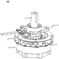
Fig. 5 is a perspective sectional view of the rotor shown in fig. 3 with a stator assembled.
Fig. 6 shows a schematic view of a power tool according to an embodiment of the present invention.
Reference numerals: 100-a motor; 1-a rotor; 11-a rotating shaft; 111-shaft portion; 112-a connecting portion; 113-ribs; 114-a fixation reinforcement; 115-axial grooves; 116-an axial bore; 12-a housing; 120-a side wall; 121-bottom wall; 122-an annular groove; 123-radial connecting section; 124-a first strut; 125-notch; 126-convex column; 127-a positioning groove; 128-via holes; 129-a second strut; 191-spacer ring; 192-a support; 193-port; 13-a cooling fan; 130-fan blades; 131-gas inflow inlet; 132-a gas flow outlet; 133-a first connecting ring; 134-a second connecting ring; 14-a magnetic yoke; 141-a body portion; 142-a first mounting groove; 143-opening; 144-a second mounting groove; 145-inner bulge; 146-an outer protrusion; 147-a pole part; 148-pole face; 15-a permanent magnet; 16-a ring connector; 161-inner through hole; 162-external through hole; 163-boss; 164-perforation; 165-notch; 2-a stator; 21-a stator core; 22-a winding; 23-a wire holder; 24-a bearing; 25-a scaffold; 300-electric tool.
Detailed Description
The invention will be described in detail with reference to the accompanying drawings and specific embodiments, so that the technical scheme and the beneficial effects of the invention are more clear. It is to be understood that the drawings are provided for purposes of illustration and description only and are not intended as a definition of the limits of the invention, but are drawn to scale.
Fig. 1 shows a perspective assembly view of a motor 100 according to an embodiment of the present invention. The motor 100 includes a rotor 1 and a stator 2 housed in the rotor 1. The stator 2 is fixedly arranged, and the rotor 1 can rotate relative to the stator 2. In the present embodiment, the motor 100 is a brushless dc motor.
Referring also to fig. 2, the rotor 1 includes a housing 12, a rotating shaft 11 fixedly connected to the housing 12, a yoke 14 received in the housing 12, and a permanent magnet 15 mounted on the yoke 14. The stator 2 includes a bracket 25, a stator core 21 and a wire holder 23 fixed to the bracket 25, and a winding 22 wound around the stator core 21. Bracket 25 is used to secure motor 100 in place or position. The stator core 21 and the wire holder 23 are fixed relative to each other. The rotating shaft 11 of the rotor 1 is rotatably supported in a bracket 25 of the stator 2 by a bearing 24 so that the rotor 1 can rotate relative to the stator 2. Referring to fig. 3 to 5 together, the rotor 1 further includes a cooling fan 13 provided on the housing 12. The rotor 1 is integrally formed by means of over-molding. Specifically, the housing 12 of the rotor 1 and the cooling fan 13 are formed by plastic injection molding, and the rotating shaft 11, the yoke 14, and the permanent magnet 15 are formed as a non-detachable integral body with the housing 12 and the cooling fan 13 by means of over-molding. In an alternative embodiment, the cooling fan 13 may be attached to the housing 12. The housing 12 is substantially in the shape of a hollow cylinder with one end open. In the present embodiment, the housing 12 includes a bottom wall 121 and a side wall 120 extending in the axial direction from the outer periphery of the bottom wall 121. The yoke 14 and the permanent magnet 15 are embedded in the side wall 120 by means of over-molding. The cooling fan 13 is annular and is disposed at the axial end of the side wall 120 remote from the bottom wall 121.
The cooling fan 13 includes a first connection ring 133 and a second connection ring 134 arranged at an interval in the axial direction, and a plurality of fan blades 130 connected between the two connection rings 133 and 134. Wherein the first connecting ring 133 is located at an axial end of the side wall 120 of the housing 12 of the rotor 1, which may be formed by an axial end face of the side wall 120. The second connection ring 134 is disposed in parallel with and spaced apart from the first connection ring 133. The fan blades 130 are uniformly arranged between the two connecting rings 133, 134 along the circumferential direction, and the adjacent fan blades 130 are spaced to form an air flow passage (or an air flow outlet 132). The fan blade 130 is connected to two connection rings 133 and 134 at its axial ends. Each fan blade 130 extends from the outer periphery of the first connecting ring 133 and the second connecting ring 134 toward the inner periphery, but in the present embodiment, the extending direction of the fan blades 130 is inclined relative to the radial direction of the housing 12, and the inclined direction of all the fan blades 130 is substantially the same.
In the present embodiment, the outer diameter of the cooling fan 13 is larger than the outer diameter of the casing 12, that is, the outer diameters of the first and second connection rings 133 and 134 are larger than the outer diameter of the casing 12. The inner diameter of the cooling fan 13 is substantially equal to the inner diameter of the casing 12.
The bottom wall 121 of the housing 12 includes a plurality of radially extending radial connecting segments 123. The radial connecting section 123 is connected to the sidewall 120. The plurality of radial connecting sections 123 are arranged at intervals along the circumferential direction, and the airflow inlets 131 are formed by the intervals between the adjacent radial connecting sections 123. In this embodiment, the bottom wall 121 further includes a spacer ring 191, and the spacer ring 191 is disposed in the bottom wall 121 coaxially with the side wall 120 and connected to the radial middle section of all the connecting sections 123, thereby spacing the airflow inlet 131 in plural in the radial direction. When the stator 2 is assembled in the housing 12 of the rotor 1, the cooling fan 13 on the housing 12 at least partially exceeds the windings 22 of the stator 2 in the axial direction thereof, so that the windings 22 are located between the bottom wall 121 of the housing 12 and the cooling fan 13 in the axial direction. The airflow inlet 131 of the housing 12 is provided corresponding to the winding 22. The winding 22 is disposed between the airflow inlet 131 and the airflow outlet 132 of the cooling fan 13 such that the winding 22 is completely disposed in the cooling area. As shown in fig. 5, when the rotor 1 is in operation, the airflow is introduced into the housing 12 from the airflow inlet 131 and passes through the energized windings 22 by the cooling fan 13, and then flows out from the airflow outlet 132, thereby cooling the windings 22 better and completely.
The rotation shaft 11 is of a one-piece construction, and includes a shaft portion 111 and a connecting portion 112 integrally extending outward in a radial direction from one end portion of the shaft portion 111. The rotary shaft 11 is integrally fixed in the housing 12 by a connecting portion 112. The connecting portion 112 is at least partially wrapped at the center of the bottom wall 121 of the housing 12. Specifically, the center of the bottom wall 121 has a support portion 192 for supporting the connection portion 112 of the rotation shaft 11, so that the rotation shaft 11 is overmolded at the bottom wall 121 of the housing 12. In this embodiment, the support 192 has a through hole 193 at the center, and the outer surface of the connecting portion 112 of the rotating shaft 11 is exposed through the through hole 193. Preferably, a plurality of protruding ribs 113 are provided on the inner surface of the connecting portion 112 of the rotation shaft 11 to further reinforce the connection and fixation of the rotation shaft 11 in the housing 12. The ribs 113 are at least partially encased in the bottom wall 121 to prevent rotation of the shaft 11 relative to the housing 12. Preferably, the ribs 113 are radially arranged on the connecting portion 112 and extend radially inward to the outer periphery of the shaft portion 111. In this embodiment, a circumferentially disposed fixation reinforcement 114 is provided between the rib 113 and the shaft portion 111 to reinforce the rib 113 and the shaft portion 111 and the connection therebetween. The fixing reinforcement portion 114 is covered in the bottom wall 121. Alternatively, the fixing reinforcement portion 114 may protrude from the bottom wall 121. The outer diameter of the fixing reinforcement part 114 on the connecting part 112 is slightly larger than that of the shaft part 111, so that the bending resistance and torsion resistance of the rotating shaft 11 are enhanced. In this embodiment, the bottom wall 121 is further provided with a plurality of notches 125 between the ribs 113 to reduce the mass of the housing 12 without affecting the stability of the shaft 11 on the bottom wall 121.
The shaft portion 111 is provided at the outer periphery thereof at the other end portion with an axial groove 115, and is opened at the center thereof with an axial hole 116, the axial groove 115 and the axial hole 116 being used for connection with a load such as a desired tool to drive the load rotation of the desired tool. Preferably, the shaft 11 is formed by a cold forging process using 45 steel (carbon structural steel, SWRCH45K), the shaft portion 111 has a diameter of 25mm, and the coupling portion 112 has a circular shape with a diameter of 60 mm. The cold forging process is adopted to process the rotating shaft 11, so that the powder metallurgy part processing process adopted in the prior art is avoided, the cost is saved, and the strength of the rotating shaft 11 is ensured. The shaft 11 is integrally formed with the shaft portion 111 and the connection portion 112 through a cold forging process, thereby saving costs and simplifying assembly of the shaft 11.
In the present embodiment, the yoke 14 is integrally embedded and housed in the side wall 120 of the housing 12. To more clearly show the specific construction of the yoke 14 and housing 12, fig. 2 presents the yoke 14 and housing 12 in an exploded condition, but in fact, since the housing 12 is overmolded outside the yoke 14, the two form an inseparable unit. Specifically, as shown in the drawing, the yoke 14 has a hollow cylindrical shape. The side wall 120 of the housing 12 is provided with an annular groove 122 surrounding the stator core 21 at the position corresponding to the stator core 21 of the stator 2. In the present embodiment, the annular groove 122 is disposed below the cooling fan 13. The yoke 14 is received in an annular groove 122 of the housing 12. The outer side of the sidewall 120 of the housing 12 is provided with a boss 126 extending radially outward and corresponding to the annular groove 122. The projection 126 is designed for the passage of the fluid plastic during the injection molding process. A positioning groove 127 is formed between two adjacent convex columns 126. A through hole 128 is formed at the bottom of the positioning groove 127, and the through hole 128 communicates with the annular groove 122. The positioning slots 127 and through holes 128 are provided for positioning the applicable support during the injection molding process to support and position the yoke 14 during the overmolding process.
The yoke 14 includes a body portion 141 and a plurality of magnetic pole portions 147 connected to the body portion 141, and the plurality of magnetic pole portions 147 are circumferentially spaced apart and are located inside the body portion 141. The inside of the body portion 141 includes a plurality of V-shaped grooves, and each magnetic pole portion 147 is connected to the body portion 141 in a corresponding V-shaped groove. In this embodiment, each magnetic pole 147 is substantially triangular. A first mounting groove 142 and a second mounting groove 144 are formed at intervals between each magnetic pole portion 147 and the opposite side surfaces of the corresponding V-shaped groove. The first and second mounting grooves 142 and 144 are arranged in a V-shape. The permanent magnets 15 with the same polarity are accommodated in the first mounting groove 142 and the second mounting groove 144, so that after the permanent magnets 15 are embedded in the first mounting groove 142 and the second mounting groove 144, the magnetic pole surface 148 between the two mounting grooves 142, 144 is magnetized into one magnetic pole, and the magnetic pole thus arranged can remarkably improve the magnetic gathering effect, thereby improving the power density of the motor 100. In the present embodiment, the permanent magnet 15 has a rectangular shape. The openings 143 are formed between the adjacent two magnetic pole portions 147 at intervals. Therefore, larger magnetic resistance can be generated, and the magnetic leakage is reduced. The body portion 141 of the yoke 14 is positioned in the case 12 through the opening 143. The housing 12 and the yoke 14 are formed with the first leg 124 engaged with the opening 143 at a position corresponding to the opening 143 inside the annular groove 122 during the overmolding process, thereby fixing the body portion 141 in the circumferential direction and the radial direction. In the present embodiment, the annular groove 122 is further formed therein with a second leg 129 engageable in the first and second mounting grooves 142 and 144 during the overmolding process to enhance the coupling strength of the housing 12 and the yoke 14. The second support 129 is integrally formed by injection molding to fix the permanent magnet 15 in the first and second mounting grooves 142 and 144 without a gap.
Preferably, a ring-shaped connecting member 16 is attached to the top end of the yoke 14. The annular connecting member 16 may be fixedly connected to the yoke 14 in a snap fit manner, thereby axially fixing the yoke 14. For example, an inner protrusion 145 may be provided at the top end of each magnetic pole portion 147, and an outer protrusion 146 may be provided at the top end of the portion of the body portion 141 between adjacent magnetic pole portions 147. Inner and outer through holes 161 and 162 through which the inner and outer protrusions 145 and 146 pass are provided on the ring-shaped connector 16, and the yoke 14 and the ring-shaped connector 16 are coupled by snap-fitting the protrusions 145 and 146 and the through holes 161 and 162. Referring to fig. 2 and 4b, the annular connecting member 16 is provided with a through hole 164, and during the overmolding process, a boss 163 for being inserted into the through hole 164 is formed on a side of the first connecting ring 133 of the cooling fan 13 facing the housing 12, so as to connect the housing 12 and the annular connecting member 16, and further, to fixedly connect the housing 12 and the yoke 14. In this embodiment, the annular connector 16 is further provided with notches 165 corresponding to the openings 143 between adjacent pole pieces 147.
The rotor 1 of the present invention is formed by over-molding, and when the housing 12 and the cooling fan 13 are formed, the integrated rotating shaft 11 having the shaft portion 111 and the connecting portion 112, the yoke 14 and the permanent magnet 15 are integrally connected, so that the rotor 1 is more easily manufactured and has a lower cost.
Fig. 6 shows an electric tool 300 having the motor 100 of the present invention, which may be, for example, a lawn mower, the motor 100 being used for mowing and driving a mowing apparatus of the lawn mower. The motor 100 of the present invention may also be used in other power tools.
The above description is only a preferred embodiment of the present invention, and the protection scope of the present invention is not limited to the above-listed embodiments, and any simple changes or equivalent substitutions of technical solutions that can be obviously obtained by those skilled in the art within the technical scope of the present invention are within the protection scope of the present invention.
Claims (12)
1. The utility model provides a rotor, includes the casing, fixes pivot on the casing, accept in yoke in the casing, and install in permanent magnet on the yoke, the casing includes the diapire and certainly the periphery of diapire is along the lateral wall of the axial extension of rotor, its characterized in that, the rotor still includes the cooling fan, the cooling fan is located the lateral wall is kept away from the axial end of diapire, the pivot includes the axial region and certainly the axial region is along the outside integrative connecting portion that extends of radial direction, the pivot yoke with the permanent magnet through coating forming's mode with the casing forms into undetachable whole.
2. The rotor as claimed in claim 1, wherein the bottom wall of the housing is formed with an air flow inlet through which an air flow is discharged by the cooling fan after entering the housing of the rotor.
3. The rotor as claimed in claim 2, wherein the cooling fan comprises a first connecting ring and a second connecting ring which are arranged at intervals along the axial direction, and a plurality of fan blades connected between the first connecting ring and the second connecting ring, and the adjacent fan blades are spaced to form an air flow outlet.
4. The rotor as set forth in claim 3 wherein said housing and said cooling fan are integrally formed by injection molding, said first connecting ring being located at said axial end of said housing of said rotor and being formed by an axial end surface of said side wall of said housing.
5. A rotor according to claim 3, wherein the direction of extension of the fan blades is inclined with respect to the radial direction of the housing.
6. The rotor of claim 2, wherein the bottom wall includes a plurality of radially disposed radially connected segments, adjacent radially connected segments being spaced apart to form the airflow inlet.
7. The rotor of claim 6 wherein the bottom wall further comprises a spacer ring disposed coaxially within the bottom wall with the side wall and connected to the radially intermediate section of the connecting segment to space the airflow inlet in a plurality in a radial direction.
8. The rotor of claim 1, wherein the connecting portion is provided with a plurality of ribs extending toward the shaft portion, the ribs being at least partially over-fixed in the bottom wall of the housing.
9. The rotor as set forth in claim 1 wherein said shaft is formed from carbon structural steel by a cold forging process.
10. An electrical machine comprising a stator and a rotor according to any one of claims 1 to 9, the stator being disposed within the rotor and the rotor being rotatable relative to the stator.
11. The electric machine of claim 10, wherein the cooling fan at least partially extends axially beyond the windings of the stator.
12. A power tool comprising the motor according to claim 10.
Priority Applications (4)
| Application Number | Priority Date | Filing Date | Title |
|---|---|---|---|
| CN202010266848.4A CN113497502A (en) | 2020-04-07 | 2020-04-07 | Electric tool, motor and rotor thereof |
| EP21785560.0A EP4135162A1 (en) | 2020-04-07 | 2021-03-12 | Electric power tool, motor, and rotor thereof |
| PCT/CN2021/080437 WO2021203909A1 (en) | 2020-04-07 | 2021-03-12 | Electric power tool, motor, and rotor thereof |
| US17/959,270 US20230031766A1 (en) | 2020-04-07 | 2022-10-03 | Electric power tool, motor, and rotor thereof |
Applications Claiming Priority (1)
| Application Number | Priority Date | Filing Date | Title |
|---|---|---|---|
| CN202010266848.4A CN113497502A (en) | 2020-04-07 | 2020-04-07 | Electric tool, motor and rotor thereof |
Publications (1)
| Publication Number | Publication Date |
|---|---|
| CN113497502A true CN113497502A (en) | 2021-10-12 |
Family
ID=77995708
Family Applications (1)
| Application Number | Title | Priority Date | Filing Date |
|---|---|---|---|
| CN202010266848.4A Pending CN113497502A (en) | 2020-04-07 | 2020-04-07 | Electric tool, motor and rotor thereof |
Country Status (4)
| Country | Link |
|---|---|
| US (1) | US20230031766A1 (en) |
| EP (1) | EP4135162A1 (en) |
| CN (1) | CN113497502A (en) |
| WO (1) | WO2021203909A1 (en) |
Families Citing this family (2)
| Publication number | Priority date | Publication date | Assignee | Title |
|---|---|---|---|---|
| EP4195465A1 (en) * | 2021-12-10 | 2023-06-14 | Black & Decker, Inc. | Power tool with compact outer-rotor motor assembly |
| CN116365753A (en) * | 2022-07-29 | 2023-06-30 | 北京金风科创风电设备有限公司 | Rotor, generator and wind generating set |
Family Cites Families (7)
| Publication number | Priority date | Publication date | Assignee | Title |
|---|---|---|---|---|
| CN101087077A (en) * | 2006-06-07 | 2007-12-12 | 梁昌勇 | Automobile permanent magnetic generator without front and rear cover |
| CN101170266A (en) * | 2006-10-23 | 2008-04-30 | 梁昌勇 | External rotor car permanent magneto |
| DE102009060959A1 (en) * | 2009-12-30 | 2011-07-07 | Robert Bosch GmbH, 70469 | transverse flux |
| FR3062253B1 (en) * | 2017-01-25 | 2020-06-12 | IFP Energies Nouvelles | CLOSED ROTATING ELECTRIC MACHINE WITH AN AIR COOLING SYSTEM OF THE MAGNETS IN THE ROTOR |
| JP6856446B2 (en) * | 2017-05-23 | 2021-04-07 | 澤藤電機株式会社 | Rotor structure in outer rotor type motor |
| CN110784129A (en) * | 2019-10-25 | 2020-02-11 | 中山市美昇电子科技有限公司 | Power drive circuit and integrated brushless motor |
| CN110829654A (en) * | 2019-11-22 | 2020-02-21 | 杭州微光电子股份有限公司 | Motor rotor |
-
2020
- 2020-04-07 CN CN202010266848.4A patent/CN113497502A/en active Pending
-
2021
- 2021-03-12 WO PCT/CN2021/080437 patent/WO2021203909A1/en unknown
- 2021-03-12 EP EP21785560.0A patent/EP4135162A1/en active Pending
-
2022
- 2022-10-03 US US17/959,270 patent/US20230031766A1/en active Pending
Also Published As
| Publication number | Publication date |
|---|---|
| EP4135162A1 (en) | 2023-02-15 |
| WO2021203909A1 (en) | 2021-10-14 |
| US20230031766A1 (en) | 2023-02-02 |
Similar Documents
| Publication | Publication Date | Title |
|---|---|---|
| CN110873061B (en) | Pump body and method for manufacturing rotor assembly for pump body | |
| US8593022B2 (en) | Electric motor with heat dissipation structure | |
| US5755557A (en) | Axial flow fan | |
| CN1685589B (en) | Outer rotor type multipolar generator | |
| EP1844239B1 (en) | Two piece separable impeller and inner drive for pump | |
| US20230031766A1 (en) | Electric power tool, motor, and rotor thereof | |
| EP1876687B1 (en) | Brushless fan motor | |
| US20190003485A1 (en) | Centrifugal fan | |
| US20010006598A1 (en) | Blower | |
| EP1536142B1 (en) | Motor-blower unit | |
| CN102130562A (en) | Electric motor | |
| CN211351856U (en) | External rotor motor | |
| CN109958636B (en) | Centrifugal fan | |
| CN217545805U (en) | Motor housing, in-wheel motor and wheel | |
| EP3951182A1 (en) | Electric fluid pump | |
| JP4423919B2 (en) | Centrifugal blower and air conditioner using the same | |
| JP6843627B2 (en) | Fan device and its manufacturing method | |
| CN108352667B (en) | Slip ring, motor and vehicle having the same | |
| CN211209409U (en) | Motor and electric product | |
| CN220067074U (en) | Outer rotor motor | |
| CN210724471U (en) | External rotor motor | |
| CN218449645U (en) | Motor and electric product | |
| CN219993983U (en) | Fan system with integrated hub, thermal management system and vehicle | |
| CN218733501U (en) | Insulating skeleton and stator module | |
| CN219139452U (en) | Rotor assembly and centrifugal pump |
Legal Events
| Date | Code | Title | Description |
|---|---|---|---|
| PB01 | Publication | ||
| PB01 | Publication | ||
| SE01 | Entry into force of request for substantive examination | ||
| SE01 | Entry into force of request for substantive examination |