CN113496480A - Method for detecting weld image defects - Google Patents
Method for detecting weld image defects Download PDFInfo
- Publication number
- CN113496480A CN113496480A CN202110524253.9A CN202110524253A CN113496480A CN 113496480 A CN113496480 A CN 113496480A CN 202110524253 A CN202110524253 A CN 202110524253A CN 113496480 A CN113496480 A CN 113496480A
- Authority
- CN
- China
- Prior art keywords
- detection
- weld
- module
- model
- network
- Prior art date
- Legal status (The legal status is an assumption and is not a legal conclusion. Google has not performed a legal analysis and makes no representation as to the accuracy of the status listed.)
- Pending
Links
- 230000007547 defect Effects 0.000 title claims abstract description 53
- 238000000034 method Methods 0.000 title claims abstract description 30
- 238000001514 detection method Methods 0.000 claims abstract description 87
- 230000006870 function Effects 0.000 claims abstract description 23
- 238000004422 calculation algorithm Methods 0.000 claims abstract description 18
- 230000005855 radiation Effects 0.000 claims abstract description 8
- 238000012549 training Methods 0.000 claims abstract description 7
- 238000004806 packaging method and process Methods 0.000 claims abstract description 4
- 238000000605 extraction Methods 0.000 claims description 26
- 238000005070 sampling Methods 0.000 claims description 14
- 230000004927 fusion Effects 0.000 claims description 9
- 210000002569 neuron Anatomy 0.000 claims description 9
- 238000004364 calculation method Methods 0.000 claims description 8
- 238000003466 welding Methods 0.000 claims description 8
- 230000001788 irregular Effects 0.000 claims description 6
- 230000000717 retained effect Effects 0.000 claims description 4
- 239000013585 weight reducing agent Substances 0.000 claims description 3
- 230000035515 penetration Effects 0.000 claims description 2
- 238000005516 engineering process Methods 0.000 abstract description 6
- 238000012545 processing Methods 0.000 abstract description 3
- 238000010586 diagram Methods 0.000 description 15
- 238000013527 convolutional neural network Methods 0.000 description 6
- 238000013461 design Methods 0.000 description 5
- 238000004458 analytical method Methods 0.000 description 4
- 230000008859 change Effects 0.000 description 3
- 238000009659 non-destructive testing Methods 0.000 description 3
- 238000007500 overflow downdraw method Methods 0.000 description 3
- 238000011160 research Methods 0.000 description 3
- 230000006399 behavior Effects 0.000 description 2
- 238000009826 distribution Methods 0.000 description 2
- 238000011156 evaluation Methods 0.000 description 2
- 230000004807 localization Effects 0.000 description 2
- 230000007246 mechanism Effects 0.000 description 2
- 238000005065 mining Methods 0.000 description 2
- 230000008569 process Effects 0.000 description 2
- 230000004913 activation Effects 0.000 description 1
- 230000003044 adaptive effect Effects 0.000 description 1
- 238000013528 artificial neural network Methods 0.000 description 1
- 238000005266 casting Methods 0.000 description 1
- 230000015556 catabolic process Effects 0.000 description 1
- 238000007418 data mining Methods 0.000 description 1
- 238000006731 degradation reaction Methods 0.000 description 1
- 238000011161 development Methods 0.000 description 1
- 230000018109 developmental process Effects 0.000 description 1
- 230000000694 effects Effects 0.000 description 1
- 230000002349 favourable effect Effects 0.000 description 1
- 238000007667 floating Methods 0.000 description 1
- 238000003709 image segmentation Methods 0.000 description 1
- 238000010801 machine learning Methods 0.000 description 1
- 238000004519 manufacturing process Methods 0.000 description 1
- 239000000463 material Substances 0.000 description 1
- 238000012986 modification Methods 0.000 description 1
- 230000004048 modification Effects 0.000 description 1
- 238000011176 pooling Methods 0.000 description 1
- OLBCVFGFOZPWHH-UHFFFAOYSA-N propofol Chemical compound CC(C)C1=CC=CC(C(C)C)=C1O OLBCVFGFOZPWHH-UHFFFAOYSA-N 0.000 description 1
- 229960004134 propofol Drugs 0.000 description 1
- 238000013139 quantization Methods 0.000 description 1
- 238000007619 statistical method Methods 0.000 description 1
- 238000006467 substitution reaction Methods 0.000 description 1
- 238000012360 testing method Methods 0.000 description 1
- 230000000007 visual effect Effects 0.000 description 1
Images


Classifications
-
- G—PHYSICS
- G06—COMPUTING; CALCULATING OR COUNTING
- G06T—IMAGE DATA PROCESSING OR GENERATION, IN GENERAL
- G06T7/00—Image analysis
- G06T7/0002—Inspection of images, e.g. flaw detection
- G06T7/0004—Industrial image inspection
-
- G—PHYSICS
- G06—COMPUTING; CALCULATING OR COUNTING
- G06F—ELECTRIC DIGITAL DATA PROCESSING
- G06F18/00—Pattern recognition
- G06F18/20—Analysing
- G06F18/21—Design or setup of recognition systems or techniques; Extraction of features in feature space; Blind source separation
- G06F18/214—Generating training patterns; Bootstrap methods, e.g. bagging or boosting
-
- G—PHYSICS
- G06—COMPUTING; CALCULATING OR COUNTING
- G06F—ELECTRIC DIGITAL DATA PROCESSING
- G06F18/00—Pattern recognition
- G06F18/20—Analysing
- G06F18/24—Classification techniques
-
- G—PHYSICS
- G06—COMPUTING; CALCULATING OR COUNTING
- G06F—ELECTRIC DIGITAL DATA PROCESSING
- G06F18/00—Pattern recognition
- G06F18/20—Analysing
- G06F18/25—Fusion techniques
- G06F18/253—Fusion techniques of extracted features
-
- G—PHYSICS
- G06—COMPUTING; CALCULATING OR COUNTING
- G06N—COMPUTING ARRANGEMENTS BASED ON SPECIFIC COMPUTATIONAL MODELS
- G06N3/00—Computing arrangements based on biological models
- G06N3/02—Neural networks
- G06N3/04—Architecture, e.g. interconnection topology
-
- G—PHYSICS
- G06—COMPUTING; CALCULATING OR COUNTING
- G06N—COMPUTING ARRANGEMENTS BASED ON SPECIFIC COMPUTATIONAL MODELS
- G06N3/00—Computing arrangements based on biological models
- G06N3/02—Neural networks
- G06N3/08—Learning methods
-
- G—PHYSICS
- G06—COMPUTING; CALCULATING OR COUNTING
- G06T—IMAGE DATA PROCESSING OR GENERATION, IN GENERAL
- G06T2207/00—Indexing scheme for image analysis or image enhancement
- G06T2207/20—Special algorithmic details
- G06T2207/20081—Training; Learning
-
- G—PHYSICS
- G06—COMPUTING; CALCULATING OR COUNTING
- G06T—IMAGE DATA PROCESSING OR GENERATION, IN GENERAL
- G06T2207/00—Indexing scheme for image analysis or image enhancement
- G06T2207/20—Special algorithmic details
- G06T2207/20084—Artificial neural networks [ANN]
-
- G—PHYSICS
- G06—COMPUTING; CALCULATING OR COUNTING
- G06T—IMAGE DATA PROCESSING OR GENERATION, IN GENERAL
- G06T2207/00—Indexing scheme for image analysis or image enhancement
- G06T2207/20—Special algorithmic details
- G06T2207/20092—Interactive image processing based on input by user
- G06T2207/20104—Interactive definition of region of interest [ROI]
-
- G—PHYSICS
- G06—COMPUTING; CALCULATING OR COUNTING
- G06T—IMAGE DATA PROCESSING OR GENERATION, IN GENERAL
- G06T2207/00—Indexing scheme for image analysis or image enhancement
- G06T2207/30—Subject of image; Context of image processing
- G06T2207/30108—Industrial image inspection
- G06T2207/30152—Solder
Landscapes
- Engineering & Computer Science (AREA)
- Theoretical Computer Science (AREA)
- Physics & Mathematics (AREA)
- Data Mining & Analysis (AREA)
- General Physics & Mathematics (AREA)
- Life Sciences & Earth Sciences (AREA)
- Artificial Intelligence (AREA)
- General Engineering & Computer Science (AREA)
- Evolutionary Computation (AREA)
- Computer Vision & Pattern Recognition (AREA)
- Evolutionary Biology (AREA)
- Bioinformatics & Computational Biology (AREA)
- Bioinformatics & Cheminformatics (AREA)
- Computational Linguistics (AREA)
- Biomedical Technology (AREA)
- Biophysics (AREA)
- Health & Medical Sciences (AREA)
- General Health & Medical Sciences (AREA)
- Molecular Biology (AREA)
- Computing Systems (AREA)
- Mathematical Physics (AREA)
- Software Systems (AREA)
- Quality & Reliability (AREA)
- Image Analysis (AREA)
Abstract
The invention provides a method for detecting weld image defects, which comprises the following steps: constructing a second-order detection network learning model; acquiring radiation image data, inputting the radiation image data into the second-order detection network learning model, and training the second-order detection network learning model to obtain a detection model; adding a deformable convolution module at the detection end of the detection model, and adding an offset domain in the deformable convolution module; and improving the loss function in the model into a variant of the cross entropy function; and detecting the weld defects and types in the weld image to be detected by adopting the improved detection model. The embodiment of the invention utilizes the digital image processing technology to preprocess the image; training a model by utilizing a built second-order Detection network model DR-Detection; and the model is convenient to call and use by packaging and storing the model. The algorithm is a weld image defect detection method based on a second-order detection network, and can reduce artificial workload and improve working efficiency.
Description
Technical Field
The invention relates to the technical field of image target detection, in particular to a method for detecting weld image defects.
Background
With the continuous deepening of informatization in the industrial field, intelligent manufacturing is a great target for industrial development and innovation. The importance of intelligent nondestructive testing evaluation is defined, and the digital radiographic image intelligent identification technology serving as an important branch of intelligent nondestructive testing evaluation is bound to become a key point and a hot point of research of nondestructive testing technology, and has high application value. The existing intelligent analysis method applicable to digital ray detection is mainly a data-driven machine learning and data mining algorithm, and comprises classification, clustering, regression, association rule mining, feature analysis and the like. The application of the above method in the industrial field requires the following problems. Firstly, different material thicknesses and process methods of casting and welding objects can cause various defect types, and related data of the defect types are high in dimensionality, complex in structure and small in sample characteristic. How to efficiently and effectively analyze the large-scale complex data, finding a feature set related to the defect from a large number of features as a label to realize intelligent detection through a computer vision technology is a difficult problem. The invention is focused on the defect detection of industrial digital radiographic images, designs a detection network and solves the actual problem of nondestructive detection in the industrial field.
Disclosure of Invention
The embodiment of the invention aims to provide a method for detecting defects of a weld image, which is dedicated to defect detection of an industrial digital radiographic image, designs a detection network and solves the actual problem of nondestructive detection in the industrial field. The specific technical scheme is as follows:
the embodiment of the invention provides a method for detecting weld image defects, which is applied to a processor and comprises the following steps:
constructing a deep second-order detection network learning model;
acquiring radiation image data, inputting the radiation image data into the deep second-order detection network learning model, and training the deep second-order detection network learning model to obtain a detection model;
adding a deformable convolution module at the detection end of the detection model, and adding an offset domain in the deformable convolution module; and improving the loss function in the model into a variant of the cross entropy function;
and detecting the weld defects and types in the weld image to be detected by adopting the improved detection model.
Further, after the step of detecting the weld defects and the types in the weld image to be detected by using the improved detection model, the method further comprises the following steps: and packaging and storing the improved detection model.
Further, in adding an offset domain to the deformable convolution module, the expression is

In the formula, fixing position p0+pn、p0+pn+ΔpnIs not fixed at a fixed position, Is a sampling grid.
Further, Δ pnComprises two degrees of freedom x and y, and y/x is less than or equal to 2.
Further, the deformable convolution module comprises symmetric convolution and asymmetric convolution; the asymmetric convolution is used for extracting irregular weld defects; the detection model comprises an inclusion-Resnet module and a DropBlock layer.
Furthermore, the DropBlock layer algorithm comprises two parameter blockssizeAnd γ; the calculation method of gamma is as follows:

in the formula, featsizeSize, keep, of the characteristic mapprobRepresenting the probability that the neuron is retained. At the end of the DropBlock algorithm, to ensure that the output scales are consistent, the output is rescaled to compensate for the discarded neurons.
Further, the weld image to be detected includes: including gas hole, crack, incomplete penetration, incomplete fusion weld defect pictures.
Further, the improved detection model comprises: the system comprises a feature extraction and classification module, an RPN network module and an ROI Align module; the feature extraction and classification module comprises: the system comprises a feature extraction network submodule, a feature fusion submodule and a detection unit submodule; the characteristic extraction and classification module is used for extracting and classifying the welding seam image to be detected; the RPN network module is used for identifying the type of the weld defect in the weld image to be detected after the weld image to be detected is processed by the feature extraction and classification module; and the ROI Align module is used for connecting the feature extraction and classification module and the RPN module.
Further, in the RPN network module, the formula of the loss function is:

in the formula, N cls256 denotes the anchor and the number of candidate boxes participating in the calculation, piRepresents the score, y, of the anchor output over the RPN networkiAnd representing a label corresponding to the anchor, wherein the rule of the label is as follows:

here we specify that anchor, which is the largest of the IOU's with the target box and IOU >0.7, is a positive sample, and that IOU <0.3 is a negative sample;
the formula for the location loss of the RPN network is:
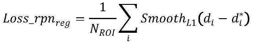
in the formula (II)ROI=128, Representing the label corresponding to each ROI, diRepresenting the output of the network;
the formula for the loss detection of the RPN network is:

in the formula (II)clsGet 128, yicThe label representing the sample in class II, formulated the same rule as the formula for the loss function, except that here the object is the 128 ROIs for the RPN output and the target box is calculated as 0/1, picIndicating the probability of a sample belonging to class c, Loss _ FclsIs the output of the final classification of the network, between 0 and 1.
Further, in the above-mentioned case,
the expression of the variant of the cross entropy function is:

where α is used to balance the importance of each sample, γ adjusts the simple sample weight reduction rate, and when γ is 0, the formula behaves as a cross entropy function; α is 0.25 and γ is 2.
The embodiment of the invention utilizes the digital image processing technology to preprocess the image; training a model by utilizing a built second-order Detection network model DR-Detection; and the model is convenient to call and use by packaging and storing the model. The algorithm is a weld image defect detection method based on a second-order detection network, and can reduce artificial workload and improve working efficiency.
Drawings
In order to more clearly illustrate the embodiments of the present invention or the technical solutions in the prior art, the drawings used in the description of the embodiments or the prior art will be briefly described below.
Fig. 1 is an algorithm flowchart of a method for detecting a defect in a weld image according to an embodiment of the present invention.
FIG. 2 is a diagram comparing standard convolution and deformable convolution modules.
FIG. 3 is a diagram of an implementation process of the deformable convolution module.
FIG. 4 is a digital radiograph defect aspect ratio histogram.
FIG. 5 is a diagram of an implementation of a deformable convolution module that limits aspect ratios.
FIG. 6 is a diagram comparing a DropBlock module with a dropout module.
Fig. 7 is a block diagram of a feature extraction network.
Fig. 8 is a diagram of a feature extraction network architecture.
FIG. 9 is a representation of the anchor in a feature map.
Fig. 10 is a schematic diagram of a feature fusion network structure.
FIG. 11 is a diagram of a DR-detection network architecture based on second order detection.
FIG. 12 is a diagram of DR-Detection network Detection results.
FIG. 13 is a schematic view of ROI Align.
FIG. 14 is a flowchart of a method for detecting defects in a weld image.
Detailed Description
In order to make the aforementioned objects, features and advantages of the present invention comprehensible, embodiments accompanied with figures are described in detail below. It is to be understood that the described embodiments are merely a few embodiments of the invention, and not all embodiments. All other embodiments, which can be derived by a person skilled in the art from the embodiments given herein without making any creative effort, shall fall within the protection scope of the present invention.
The terms of art referred to in this example are interpreted:
the Faster R-CNN is mainly divided into two parts:
RPN (region Proposal network) generates high quality region Proposal;
fast R-CNN was tested using region propofol.
The technical solution in the embodiment of the present invention will be described below with reference to the accompanying drawings in the embodiment of the present invention.
The embodiment of the invention aims to provide a method for detecting weld image defects, which aims to solve the problems of low efficiency and low precision in the existing detection method.
Example 1
In a first aspect, referring to fig. 1 and 14, an embodiment of the present invention provides a method for detecting a defect in a weld image, applied to a processor, including:
s110, constructing a deep second-order detection network learning model.
S120, acquiring radiation image data, inputting the radiation image data into the deep second-order detection network learning model, and training the deep second-order detection network learning model to obtain a detection model.
S130, adding a deformable convolution module at the detection end of the detection model, and adding an offset domain in the deformable convolution module; and the loss function within the model is modified to be a variant of the cross-entropy function.
S140, detecting the welding seam defects and types in the welding seam image to be detected by adopting the improved detection model.
Specifically, this embodiment provides an algorithm flow for intelligent detection of weld defects, including:
designing each Detection module, and constructing a deep neural network Detection model DR-Detection through a basic module.
The model is trained using image ray data.
And the model is packaged and stored, so that the next calling and testing are convenient.
Compared with the existing weld defect detection algorithm, the algorithm has the following advantages.
Compared with the existing target algorithm, the method has higher precision on the digital radiographic image.
Traditional object detection algorithms such as fast-rcnn, YOLO, and SSD are mostly based on ImageNet image datasets, which are mainly images from general camera systems. Digital radiographic images have their own characteristics and need to be specially designed for the image characteristics. The DR-Detection finally formed by the invention is a target Detection network specially aiming at the welding seam image, and has higher precision on the welding seam image than the traditional frame and network.
The special network design for the weld images in the algorithm is a set of network model building and training specially oriented to digital radiographic images, and can meet actual requirements.
Example 2
Aiming at the deformable convolution design of long and narrow defects, the deformable convolution technology is adopted, the modeling limitation of the traditional CNN is eliminated through the change of the CNN sampling mode, and the feature extraction capability of the CNN on irregular images is enhanced.
In a two-dimensional convolution, for each point on the output signature, two components are included: and carrying out grid sampling on the input characteristic diagram and operating sampling points in a multiplying and adding mode. The grid extent of this sampling represents the receptive field of the CNN itself, and for a 3 × 3 convolution, for example, this sampling grid can be defined as:

for a point p in the output profile0In terms of its value, it solves for:

in deformable convolution, it is aimed at sampling grid There is one offset field corresponding to each value in the field and the grid
 Corresponding, is described as {
 Δ p n1, …, N }, wherein Then the output profile solving equation is:

this results in a fixed position p in the sampling mode0+pnInto a non-fixed form p0+pn+ΔpnWherein Δ pnIs why the deformable convolution can adapt to irregular objects. And in the feature map, the sampling points, namely p, are always required0、pnAnd Δ pnAre all integers if the sample point p0+pn+ΔpnAnd if the pixel is not an integer point pixel, performing interpolation solution by using a bilinear interpolation formula. The difference between the deformable convolution and the standard convolution is shown in fig. 2.
As can be seen from fig. 2, the deformable convolution is more adaptive to the characteristics of the defect itself for irregular long and narrow type defects. For deformable convolution, it is not the convolution kernel that deforms because of the point p in the output feature map0The sample point in the original is still p0+pnThis is a 3 x 3 grid as with the standard convolution, whose true deformation occurs at the learned offset Δ pnThis allows the sample points to be characterized elsewhere, with positional offsets, so the key to the deformable convolution is how to learn this offset. In the implementation, two layers of standard convolution implementation are adopted, the first layer of convolution is used to learn the offset, then the feature map is readjusted according to the offset, and finally the standard convolution correlation calculation is used, and the flow is described as shown in fig. 3:
for a feature map with an input dimension N, the learned offset is 2, which includes two degrees of freedom: x and y, respectively. The two degrees of freedom are not limited, and the distribution of the two degrees of freedom in the whole two-dimensional space is difficult to learn, the invention combines the characteristics of digital rays to limit the two degrees of freedom and reduce the searching cost of the two degrees of freedom in the two-dimensional space, and the statistical analysis is carried out on the width-to-length ratio of defects to obtain:
from FIG. 4 it can be seen that the width to length ratio of the defect is much less than 2, and therefore the present invention limits Δ pnThe ratio y/x of the two degrees of freedom x and y is less than or equal to 2, namely the two degrees of freedom are independently processed, aiming at the long and narrow characteristic of the welding seam image, the invention mainly limits the length x in code realization, and the flow is described as followsAs shown in fig. 5.
This activation function we denote as:

example 3
The invention provides a network suitable for digital radiographic image feature extraction.
The data dimension can be well expanded by an inclusion series network in a plurality of network structures, the ResNet network is designed aiming at the network degradation and the network depth deepening, the feature dimension is expanded by combining the two, the network layer number can be deepened, and the deeper features can be extracted. The network designed by the invention uses an increment-Resnet module, and in order to enhance the feature extraction of the network on the unwelded through type long and narrow defects, a B module is also used, wherein the B module comprises convolution of 1 x 7 and 7 x 1, and the asymmetric convolution is adopted to facilitate the feature extraction on irregular defects. On the basis of the original module, considering that the digital radiographic image has simple semantics, in order to avoid overfitting, a DropBlock layer is embedded in the module. The traditional dropout layer avoids overfitting by discarding neurons with a certain probability, and this method is often used in a fully connected layer. The convolutional layer utilizes a receptive field mechanism of a human visual system, namely, each position in the feature map has a receptive field, only one pixel is discarded, but a small receptive field is discarded, but other senses also exist, and the pixel value can be inferred from other receptive fields, so that the behavior of discarding only one pixel is considered as the behavior of discarding only one pixel cannot reduce the feature range for the convolutional layer, and the network can learn lost semantic information through neighborhood information, so that the network robustness cannot be increased. To do this, DropBlock takes the whole block of pixel dropping, which is essentially zeroing out the features of the store, to force the web to learn more robust features. A comparison of DropBlock with the traditional dropout is shown in FIG. 6:
in fig. 6, (a) shows a conventional dropout, and a green box shows a feature of a target, and (b) shows DropBlock, which masks features of a square around a selected point. Its specific algorithm is shown in table 1:

TABLE 1 DropBlock Algorithm
There are two parameter blocks in DropBlock algorithmsizeAnd gamma, the proposed block given in the present inventionsizeIs 7 and gamma is calculated by first determining the ratio at which the neuron is retained and then calculating the bernoulli distribution parameter that the neuron should have.

In the formula, featsizeSize, keep, of the characteristic mapprobRepresenting the probability that the neuron is retained. At the end of the DropBlock algorithm, to ensure that the output scales are consistent, the output is rescaled to compensate for the discarded neurons.
After the DropBlock structure is added, the finally used module is shown in FIG. 7;
the final feature extraction network structure is shown in fig. 8, the size and channel of the feature map are not changed in the module a and the module B, the down-sampling of the image and the change of the channel number are realized by the convolution of 3 × 3, the × 2 in fig. 8 indicates that the structure is repeated twice, and the first convolution kernel of 3 × 3 does not change the channel number when the module is repeated, and the second convolution kernel of 3 × 3 changes the channel number. Finally, the global pooling layer is used to replace the full connection layer to tile the features for Softmax classification,
the present invention places the modified deformable convolution layer on the last feature map because the use of deformable convolution is more demanding on the feature map and it is expected that the bias of the feature map itself will be learned only for well-defined feature maps.
Example 4
The multi-scale feature fusion method aiming at the defects of the digital radiographic image comprises an anchor size design method and a feature pyramid-based feature fusion method.
Firstly, explaining a method for designing the size of the anchor, the invention divides different anchors into characteristic diagrams with different sizes, so that different characteristic diagrams can detect different targets aiming at different anchors. Based on the principle that a large feature map always has a smaller receptive field, the feature scaling of an image is not obvious and is suitable for detecting a feature map with a small size, and a feature map with a small size has a larger receptive field and is suitable for detecting a large target, the method divides the anchors into 3 groups which respectively correspond to feature maps with different sizes:
TABLE 2 correspondence between characteristic diagrams and anchors


Compared with the original fast-rcnn method that 9 preset anchors are used at each pixel point, the method presets 2 anchors at each pixel point, so that the workload can be greatly reduced, the anchors are set for defect analysis of digital radiographic images, the anchors are more in line with the research scene of the method, and the regions where the defects are located can be extracted to serve as candidate regions. The anchor generated by clustering analysis gathers the defect knowledge information, belongs to prior knowledge, and the exploration and adjustment on the prior knowledge are more efficient than the search according to the spatial structure of the solution. In order to show the effect of processing different-size features by different feature maps, a small grid in an image represents a feature unit, and the appearance of an anchor in the feature map is shown in fig. 9.
Then, a feature pyramid-based feature fusion method is explained. In the invention, the addition of the feature map fusion mode is changed into splicing, the original feature channel is changed into a half by 1 × 1 convolution, the associated information from different feature maps is learned by 1 × 1 convolution after the feature maps are spliced together, thus the position information and the semantic information are fully reserved under the condition of not increasing the calculated amount, and the finally used feature fusion structure chart 10 is shown.
The invention performs up-sampling by a bilinear interpolation method, and then corrects the sampled characteristics by a convolution of 3 multiplied by 3, thereby increasing the characteristic details. As can be seen from the above diagram, the feature map of the second layer in the feature extraction network is merged with the feature map of the last layer after being convolved by two 1 × 1 volumes and 2 3 × 3 volumes, and compared with the feature extraction network which needs 2 blocks B, 2 3 × 3 volumes and 1 deformable convolution module, the path is shorter, which is more favorable for the flow of position information. Specific implementation of the Block module and the deformable convolution module in fig. 10 referring to the related content of example 2, three feature maps P with different sizes but 256 channels are finally output1、P2And P3。
Example 5
A DR-Detection network for the digital radiographic image is constructed based on the feature extraction network.
The feature extraction framework network of the invention uses the feature extraction network proposed in embodiment 2, on this basis, the invention performs feature fusion by applying an improved feature pyramid, then applies an attention mechanism to an RPN network to improve Detection accuracy, and in order to reduce position deviation caused by integer quantization, uses ROI Align to replace original ROI posing, and finally uses a full connection layer to perform classification and positioning, the overall structure of the network is shown in fig. 11, wherein each module is designed in detail in relevant sections, and the invention is called as a DR-Detection network, and finally end-to-end Detection is realized, and the Detection result is shown in fig. 12.
The whole network architecture can be seen as comprising three parts, wherein one part is the feature extraction and classification formed by the feature extraction network and the feature fusion and detection unit, the other part is the relatively independent RPN network, and the ROI Align part is used for connecting the two parts. Since the ROI Align itself contains no trainable parameters, the result of the RPN and the result of the detection unit mainly affect the accuracy of the network, so the loss function of the network mainly consists of two parts: RPN loss and detection loss. ROIAlign, RPN loss, and detection loss are explained below.
1) ROIAlign component
The ROI Align is a structure which is proposed for Mask RCNN and used for improving image segmentation accuracy, and maps candidate frame features into feature position errors output in a fixed dimension by optimizing two rounding operations in ROI posing. In the invention, floating point numbers are reserved for the pixels of the corresponding feature map after the candidate frame is downsampled, and rounding operation is not carried out. As shown in the following figure, for 56/16 ═ 3.5, the 3.5 unknown eigenvalue is obtained by the bilinear interpolation method of equations 3-13 using the four integer points adjacent to the unknown eigenvalue, while for the 3.5 × 3.5 eigen region divided into 2 × 2 grids, four sampling points are generated, the eigenvalues of the four points are also calculated by the bilinear interpolation method, and finally 5 sampling points in each grid are averaged to obtain the eigenvalue of the grid.
According to the ROI Align diagram of fig. 13, the present invention performs the calculation of dividing the input features of different sizes into 4 × 4 grid, 2 × 2 grid and 1 × 1 grid, and if the channels of the feature map are all 256, the feature of any size is converted into (4 × 4+2 × 2+1 × 1) × 256 ═ 5376 dimension, which will be used for classification and further adjustment of the output candidate frame.
2) Loss of RPN
The RPN aims to accurately distinguish whether the anchor belongs to the foreground or the background, and primarily adjusts the anchor to enable the anchor to be closer to a real target position, so that the loss of the part comprises two parts, one part is classified loss, and the anchor is judged to be foreground and background accuracy; another part is the loss of position fix, the accuracy of the adjustment to the true position for the anchor.
Although the binary classification in RPN is for all anchors, it actually affects the result by the candidate frame that is eventually entered as input into ROI Align, so the classification penalty only computes the candidate frame with RPN _ batch size 256 that is finally generated. The partial calculation formula is as follows:

in the formula, N cls256 denotes the anchor and the number of candidate boxes participating in the calculation, piRepresents the score, y, of the anchor output over the RPN networkiAnd representing a label corresponding to the anchor, wherein the rule of the label is as follows:

here we specify that anchor with IOU max of the target box and IOU >0.7 is a positive sample, and that IOU <0.3 is a negative sample, others are not considered.
When the positioning loss of the RPN is calculated, only the candidate frame which divides the anchor into the foreground is used, because the negative samples do not participate in the following detection and positioning, each anchor corresponds to four adjusting variables which respectively represent the horizontal and vertical coordinates, the width and the height of the central point of the anchor to be adjusted, and the corresponding adjusting value of each anchor and the target frame with the maximum IOU can be inversely deduced according to the following formula:

the four variables that can be used to calculate the adjustment target for each anchor represent continuous variables, where the regression loss is calculated using the Smooth L1 loss, using the formula:

the localization loss of this ROI will be followed by a corresponding addition of four variables, and the localization loss of the RPN network can be expressed as:

in the formula (II)ROI=128, Representing the label corresponding to each ROI, diRepresenting the output of the network.
3) Detecting loss
The ROI passed down the RPN network has half 128 of RPN _ batch size, and the classification for this part is a multi-classification problem, and the penalty for this part is defined as:

in the formula (II)clsGet 128, yicThe label representing sample i in class c, formulated the same rule as the formula for the loss function, except that here the object is 128 ROIs for the RPN output and the target box is calculated as 0/1, picThe probability that the sample i belongs to class c is the output of the final classification of the network, between 0 and 1.
The invention also uses the Focal loss for mining samples difficult to learn in a second-order detection framework, the loss function attributes the problem of unbalance of positive and negative samples to a large number of simple samples, namely background classes, trained in a classifier, and promotes model learning of samples difficult to classify by giving the samples small loss weight and giving south classification samples large loss weight, and the loss function belongs to a variant of a cross entropy function and is expressed as:

where α is used to balance the importance of each sample, γ adjusts the simple sample weight reduction rate, and when γ is 0, the equation behaves as a cross-entropy function. According to the research, the invention takes alpha as 0.25 and gamma as 2.
Finally, it should be noted that: the above embodiments are only used to illustrate the technical solution of the present invention, and not to limit the same; while the invention has been described in detail and with reference to the foregoing embodiments, it will be understood by those skilled in the art that: the technical solutions described in the foregoing embodiments may still be modified, or some or all of the technical features may be equivalently replaced; and the modifications or the substitutions do not make the essence of the corresponding technical solutions depart from the scope of the technical solutions of the embodiments of the present invention.
Claims (10)
1. A method for detecting weld image defects is applied to a processor and is characterized by comprising the following steps:
constructing a deep second-order detection network learning model;
acquiring radiation image data, inputting the radiation image data into the deep second-order detection network learning model, and training the deep second-order detection network learning model to obtain a detection model;
adding a deformable convolution module at the detection end of the detection model, and adding an offset domain in the deformable convolution module; and improving the loss function in the model into a variant of the cross entropy function;
and detecting the weld defects and types in the weld image to be detected by adopting the improved detection model.
2. The method for detecting the weld image defects according to claim 1, further comprising the following steps after the step of detecting the weld defects and types in the weld image to be detected by using the improved detection model: and packaging and storing the improved detection model.
3. The method for detecting weld image defects according to claim 1, wherein in the deformable convolution module, an offset domain is added with the expression of

In the formula, fixPosition p0+pn、p0+pn+ΔpnIs not fixed at a fixed position, Is a sampling grid.
4. The weld image defect detection method according to claim 3, wherein Δ p isnComprises two degrees of freedom x and y, and y/x is less than or equal to 2.
5. The weld image defect detection method according to claim 1, wherein the deformable convolution module comprises a symmetric convolution, an asymmetric convolution; the asymmetric convolution is used for extracting irregular weld defects; the detection model comprises an inclusion-Resnet module and a DropBlock layer.
6. The weld image defect detection method according to claim 5, wherein the DropBlock layer algorithm comprises two parameter blockssizeAnd γ; the calculation method of gamma is as follows:

in the formula, featsizeSize, keep, of the characteristic mapprobRepresenting the probability of a neuron being retained; at the end of the DropBlock algorithm, to ensure that the output scales are consistent, the output is rescaled to compensate for the discarded neurons.
7. The weld image defect detection method according to claims 1-6, wherein the weld image to be detected comprises: including gas hole, crack, incomplete penetration, incomplete fusion weld defect pictures.
8. The weld image defect detection method according to the claims 1 to 6, wherein the improved detection model comprises the following steps: the system comprises a feature extraction and classification module, an RPN network module and an ROI Align module; the feature extraction and classification module comprises: the system comprises a feature extraction network submodule, a feature fusion submodule and a detection unit submodule; the characteristic extraction and classification module is used for extracting and classifying the welding seam image to be detected; the RPN network module is used for identifying the type of the weld defect in the weld image to be detected after the weld image to be detected is processed by the feature extraction and classification module; the ROIAlign module is used for connecting the feature extraction and classification module and the RPN module.
9. The method for detecting weld image defects according to claim 8, wherein in the RPN network module, the formula of the loss function is as follows:

in the formula, Ncls256 denotes the anchor and the number of candidate boxes participating in the calculation, piRepresents the score, y, of the anchor output over the RPN networkiAnd representing a label corresponding to the anchor, wherein the rule of the label is as follows:

here we specify that anchor, which is the largest of the IOU's with the target box and IOU >0.7, is a positive sample, and that IOU <0.3 is a negative sample;
the formula for the location loss of the RPN network is:

in the formula (II)ROI=128, Showing each ROI pairCorresponding label, diRepresenting the output of the network;
the formula for the loss detection of the RPN network is:

in the formula (II)clsGet 128, yicThe label representing the sample in class II, formulated the same rule as the formula for the loss function, except that here the object is the 128 ROIs for the RPN output and the target box is calculated as 0/1, picIndicating the probability of a sample belonging to class c, Loss _ FclsIs the output of the final classification of the network, between 0 and 1.
10. The weld image defect detection method according to claims 1 to 6,
the expression of the variant of the cross entropy function is:

where α is used to balance the importance of each sample, γ adjusts the simple sample weight reduction rate, and when γ is 0, the formula behaves as a cross entropy function; α is 0.25 and γ is 2.
Priority Applications (1)
| Application Number | Priority Date | Filing Date | Title |
|---|---|---|---|
| CN202110524253.9A CN113496480A (en) | 2021-05-13 | 2021-05-13 | Method for detecting weld image defects |
Applications Claiming Priority (1)
| Application Number | Priority Date | Filing Date | Title |
|---|---|---|---|
| CN202110524253.9A CN113496480A (en) | 2021-05-13 | 2021-05-13 | Method for detecting weld image defects |
Publications (1)
| Publication Number | Publication Date |
|---|---|
| CN113496480A true CN113496480A (en) | 2021-10-12 |
Family
ID=77997947
Family Applications (1)
| Application Number | Title | Priority Date | Filing Date |
|---|---|---|---|
| CN202110524253.9A Pending CN113496480A (en) | 2021-05-13 | 2021-05-13 | Method for detecting weld image defects |
Country Status (1)
| Country | Link |
|---|---|
| CN (1) | CN113496480A (en) |
Cited By (4)
| Publication number | Priority date | Publication date | Assignee | Title |
|---|---|---|---|---|
| CN113888542A (en) * | 2021-12-08 | 2022-01-04 | 常州微亿智造科技有限公司 | Product defect detection method and device |
| CN114565802A (en) * | 2021-12-15 | 2022-05-31 | 北京信息科技大学 | Wind driven generator extraction method |
| CN114943843A (en) * | 2022-06-14 | 2022-08-26 | 河北工业大学 | Welding defect detection method based on shape perception |
| CN118279567A (en) * | 2024-05-30 | 2024-07-02 | 合肥工业大学 | Construction method of target detection model and road crack detection method |
Citations (3)
| Publication number | Priority date | Publication date | Assignee | Title |
|---|---|---|---|---|
| CN109285139A (en) * | 2018-07-23 | 2019-01-29 | 同济大学 | A kind of x-ray imaging weld inspection method based on deep learning |
| CN110570410A (en) * | 2019-09-05 | 2019-12-13 | 河北工业大学 | Detection method for automatically identifying and detecting weld defects |
| AU2020101011A4 (en) * | 2019-06-26 | 2020-07-23 | Zhejiang University | Method for identifying concrete cracks based on yolov3 deep learning model |
-
2021
- 2021-05-13 CN CN202110524253.9A patent/CN113496480A/en active Pending
Patent Citations (3)
| Publication number | Priority date | Publication date | Assignee | Title |
|---|---|---|---|---|
| CN109285139A (en) * | 2018-07-23 | 2019-01-29 | 同济大学 | A kind of x-ray imaging weld inspection method based on deep learning |
| AU2020101011A4 (en) * | 2019-06-26 | 2020-07-23 | Zhejiang University | Method for identifying concrete cracks based on yolov3 deep learning model |
| CN110570410A (en) * | 2019-09-05 | 2019-12-13 | 河北工业大学 | Detection method for automatically identifying and detecting weld defects |
Non-Patent Citations (7)
| Title |
|---|
| SANG-JIN OH ET ALL.: "Automatic Detection of Welding Defects Using Faster R-CNN", 《APPLIED SCIENCES》 * |
| 吴晓元: "Mask R-CNN对工业CT图像缺陷的检测和分割", 《中国优秀硕士学位论文全文数据库(电子期刊)信息科技辑》 * |
| 李楚君: "基于深度卷积神经网络的混凝土CT图像破损特征识别研究", 《中国优秀硕士学位论文全文数据库(电子期刊) 工程科技Ⅱ辑》 * |
| 董洪义: "《深度学习之PyTorch物体检测实战》", 31 January 2020, 机械工业出版社 * |
| 藤田一弥等: "《实践深度学习》", 31 October 2020, 机械工业出版社 * |
| 郭培林: "基于深度学习的轮胎X光图像瑕疵检测技术研究", 《中国优秀硕士学位论文全文数据库(电子期刊) 工程科技Ⅰ辑》 * |
| 黄旭丰: "基于深度迁移学习的焊接质量在线监测方法研究", 《中国优秀硕士学位论文全文数据库(电子期刊) 工程科技Ⅰ辑》 * |
Cited By (5)
| Publication number | Priority date | Publication date | Assignee | Title |
|---|---|---|---|---|
| CN113888542A (en) * | 2021-12-08 | 2022-01-04 | 常州微亿智造科技有限公司 | Product defect detection method and device |
| CN114565802A (en) * | 2021-12-15 | 2022-05-31 | 北京信息科技大学 | Wind driven generator extraction method |
| CN114943843A (en) * | 2022-06-14 | 2022-08-26 | 河北工业大学 | Welding defect detection method based on shape perception |
| CN114943843B (en) * | 2022-06-14 | 2024-06-25 | 河北工业大学 | Welding defect detection method based on shape sensing |
| CN118279567A (en) * | 2024-05-30 | 2024-07-02 | 合肥工业大学 | Construction method of target detection model and road crack detection method |
Similar Documents
| Publication | Publication Date | Title |
|---|---|---|
| Yu et al. | A real-time detection approach for bridge cracks based on YOLOv4-FPM | |
| CN109859190B (en) | Target area detection method based on deep learning | |
| CN109886066B (en) | Rapid target detection method based on multi-scale and multi-layer feature fusion | |
| CN108830285B (en) | Target detection method for reinforcement learning based on fast-RCNN | |
| CN111145174B (en) | 3D target detection method for point cloud screening based on image semantic features | |
| CN111461212B (en) | Compression method for point cloud target detection model | |
| CN113496480A (en) | Method for detecting weld image defects | |
| CN111179217A (en) | Attention mechanism-based remote sensing image multi-scale target detection method | |
| CN110287826B (en) | Video target detection method based on attention mechanism | |
| CN109583483A (en) | A kind of object detection method and system based on convolutional neural networks | |
| CN107103317A (en) | Fuzzy license plate image recognition algorithm based on image co-registration and blind deconvolution | |
| CN113609896A (en) | Object-level remote sensing change detection method and system based on dual-correlation attention | |
| CN113592911B (en) | Apparent enhanced depth target tracking method | |
| CN111768388A (en) | Product surface defect detection method and system based on positive sample reference | |
| CN113920468B (en) | Multi-branch pedestrian detection method based on cross-scale feature enhancement | |
| CN111738055A (en) | Multi-class text detection system and bill form detection method based on same | |
| CN108230330B (en) | Method for quickly segmenting highway pavement and positioning camera | |
| CN114299383A (en) | Remote sensing image target detection method based on integration of density map and attention mechanism | |
| CN114332473A (en) | Object detection method, object detection device, computer equipment, storage medium and program product | |
| CN114332921A (en) | Pedestrian detection method based on improved clustering algorithm for Faster R-CNN network | |
| CN117372898A (en) | Unmanned aerial vehicle aerial image target detection method based on improved yolov8 | |
| CN112308040A (en) | River sewage outlet detection method and system based on high-definition images | |
| CN115147418A (en) | Compression training method and device for defect detection model | |
| CN117853955A (en) | Unmanned aerial vehicle small target detection method based on improved YOLOv5 | |
| CN113361496B (en) | City built-up area statistical method based on U-Net |
Legal Events
| Date | Code | Title | Description |
|---|---|---|---|
| PB01 | Publication | ||
| PB01 | Publication | ||
| SE01 | Entry into force of request for substantive examination | ||
| SE01 | Entry into force of request for substantive examination | ||
| RJ01 | Rejection of invention patent application after publication |
Application publication date: 20211012 |
|
| RJ01 | Rejection of invention patent application after publication |