CN113490936A - Face authentication device and face authentication method - Google Patents
Face authentication device and face authentication method Download PDFInfo
- Publication number
- CN113490936A CN113490936A CN202080017578.1A CN202080017578A CN113490936A CN 113490936 A CN113490936 A CN 113490936A CN 202080017578 A CN202080017578 A CN 202080017578A CN 113490936 A CN113490936 A CN 113490936A
- Authority
- CN
- China
- Prior art keywords
- face
- user
- authentication
- face authentication
- image
- Prior art date
- Legal status (The legal status is an assumption and is not a legal conclusion. Google has not performed a legal analysis and makes no representation as to the accuracy of the status listed.)
- Pending
Links
Images


Classifications
-
- G—PHYSICS
- G07—CHECKING-DEVICES
- G07C—TIME OR ATTENDANCE REGISTERS; REGISTERING OR INDICATING THE WORKING OF MACHINES; GENERATING RANDOM NUMBERS; VOTING OR LOTTERY APPARATUS; ARRANGEMENTS, SYSTEMS OR APPARATUS FOR CHECKING NOT PROVIDED FOR ELSEWHERE
- G07C9/00—Individual registration on entry or exit
- G07C9/00174—Electronically operated locks; Circuits therefor; Nonmechanical keys therefor, e.g. passive or active electrical keys or other data carriers without mechanical keys
- G07C9/00563—Electronically operated locks; Circuits therefor; Nonmechanical keys therefor, e.g. passive or active electrical keys or other data carriers without mechanical keys using personal physical data of the operator, e.g. finger prints, retinal images, voicepatterns
-
- G—PHYSICS
- G06—COMPUTING; CALCULATING OR COUNTING
- G06F—ELECTRIC DIGITAL DATA PROCESSING
- G06F3/00—Input arrangements for transferring data to be processed into a form capable of being handled by the computer; Output arrangements for transferring data from processing unit to output unit, e.g. interface arrangements
- G06F3/14—Digital output to display device ; Cooperation and interconnection of the display device with other functional units
- G06F3/147—Digital output to display device ; Cooperation and interconnection of the display device with other functional units using display panels
-
- G—PHYSICS
- G06—COMPUTING; CALCULATING OR COUNTING
- G06F—ELECTRIC DIGITAL DATA PROCESSING
- G06F21/00—Security arrangements for protecting computers, components thereof, programs or data against unauthorised activity
- G06F21/30—Authentication, i.e. establishing the identity or authorisation of security principals
- G06F21/31—User authentication
- G06F21/32—User authentication using biometric data, e.g. fingerprints, iris scans or voiceprints
-
- G—PHYSICS
- G06—COMPUTING; CALCULATING OR COUNTING
- G06F—ELECTRIC DIGITAL DATA PROCESSING
- G06F3/00—Input arrangements for transferring data to be processed into a form capable of being handled by the computer; Output arrangements for transferring data from processing unit to output unit, e.g. interface arrangements
- G06F3/14—Digital output to display device ; Cooperation and interconnection of the display device with other functional units
-
- G—PHYSICS
- G06—COMPUTING; CALCULATING OR COUNTING
- G06T—IMAGE DATA PROCESSING OR GENERATION, IN GENERAL
- G06T7/00—Image analysis
-
- G—PHYSICS
- G06—COMPUTING; CALCULATING OR COUNTING
- G06V—IMAGE OR VIDEO RECOGNITION OR UNDERSTANDING
- G06V20/00—Scenes; Scene-specific elements
- G06V20/40—Scenes; Scene-specific elements in video content
- G06V20/44—Event detection
-
- G—PHYSICS
- G06—COMPUTING; CALCULATING OR COUNTING
- G06V—IMAGE OR VIDEO RECOGNITION OR UNDERSTANDING
- G06V40/00—Recognition of biometric, human-related or animal-related patterns in image or video data
- G06V40/10—Human or animal bodies, e.g. vehicle occupants or pedestrians; Body parts, e.g. hands
- G06V40/16—Human faces, e.g. facial parts, sketches or expressions
- G06V40/172—Classification, e.g. identification
-
- G—PHYSICS
- G07—CHECKING-DEVICES
- G07C—TIME OR ATTENDANCE REGISTERS; REGISTERING OR INDICATING THE WORKING OF MACHINES; GENERATING RANDOM NUMBERS; VOTING OR LOTTERY APPARATUS; ARRANGEMENTS, SYSTEMS OR APPARATUS FOR CHECKING NOT PROVIDED FOR ELSEWHERE
- G07C9/00—Individual registration on entry or exit
- G07C9/30—Individual registration on entry or exit not involving the use of a pass
- G07C9/32—Individual registration on entry or exit not involving the use of a pass in combination with an identity check
- G07C9/37—Individual registration on entry or exit not involving the use of a pass in combination with an identity check using biometric data, e.g. fingerprints, iris scans or voice recognition
-
- H—ELECTRICITY
- H04—ELECTRIC COMMUNICATION TECHNIQUE
- H04N—PICTORIAL COMMUNICATION, e.g. TELEVISION
- H04N7/00—Television systems
- H04N7/18—Closed-circuit television [CCTV] systems, i.e. systems in which the video signal is not broadcast
-
- H—ELECTRICITY
- H04—ELECTRIC COMMUNICATION TECHNIQUE
- H04N—PICTORIAL COMMUNICATION, e.g. TELEVISION
- H04N7/00—Television systems
- H04N7/18—Closed-circuit television [CCTV] systems, i.e. systems in which the video signal is not broadcast
- H04N7/183—Closed-circuit television [CCTV] systems, i.e. systems in which the video signal is not broadcast for receiving images from a single remote source
-
- G—PHYSICS
- G07—CHECKING-DEVICES
- G07C—TIME OR ATTENDANCE REGISTERS; REGISTERING OR INDICATING THE WORKING OF MACHINES; GENERATING RANDOM NUMBERS; VOTING OR LOTTERY APPARATUS; ARRANGEMENTS, SYSTEMS OR APPARATUS FOR CHECKING NOT PROVIDED FOR ELSEWHERE
- G07C9/00—Individual registration on entry or exit
- G07C9/30—Individual registration on entry or exit not involving the use of a pass
- G07C9/38—Individual registration on entry or exit not involving the use of a pass with central registration
Abstract
A face authentication device (1) is provided with: a face image acquisition unit (camera (11)) that acquires a real-time image of a predetermined imaging area in a facility, said real-time image including a face image of a user; a display unit (display (12)) that displays the progress of face authentication of the face image contained in the live image acquired by the face image acquisition unit; and a processor (control unit (15)) that controls the face image acquisition unit and the display unit, wherein the processor is configured to: when a user is detected from a live image, two or more notification screens showing the progress status are sequentially displayed on the display unit.
Description
Technical Field
The present disclosure relates to a face authentication machine and a face authentication method that perform a face authentication process based on image data obtained by photographing a subject person.
Background
Conventionally, a system has been developed in which the face authentication of a subject is applied to the opening and closing control of a shutter through which the subject passes. For example, a face authentication system is known, which includes: a reading unit that receives an identifier transmitted from a wireless tag (remote-type IC card) held by a user; an acquisition unit that acquires a facial feature amount registered in association with the identifier received from the wireless tag; an image pickup unit for picking up an image of a user; an extraction unit that extracts a feature amount of a face from image data captured by the imaging unit; a face comparison unit that compares whether or not the feature amount of the face extracted by the extraction unit matches the feature amount of the face acquired by the acquisition unit; and an opening/closing control unit that opens or closes the outlet of the shutter based on the result of the comparison by the face comparison unit (see patent document 1).
Documents of the prior art
Patent document
Patent document 1: international publication No. 2018/181968
Disclosure of Invention
In addition, in the above-described conventional technology, although the target person of face authentication (i.e., the registered face feature amount) can be locked based on the identifier transmitted from the wireless tag of the user, it is difficult to securely manage the personal information (i.e., information capable of identifying a specific individual) included in the IC card because the user passing through the gate needs to always carry the IC card. In addition, in the above-described related art, a structure in which both data of the face image data and the feature amount data thereof are placed in a cloud server or the like to safely manage these data is not considered at all.
In addition, in the face authentication system, it may take a certain amount of time from the time when the face of the user is captured until the authentication result is finally obtained, and in this case, no consideration is given to a configuration for notifying the user of the progress of the face authentication.
Accordingly, a main object of the present disclosure is to provide a face authentication machine and a face authentication method that can safely manage personal information of a user who uses a facility and allow the user to easily recognize the progress of face authentication.
A face authentication device according to the present disclosure, when an event occurs based on a behavior of a user in a facility, requests a face authentication server that performs face authentication of the user of the facility to perform a process of the face authentication, and notifies the user of an authentication result thereof, the face authentication device including: a face image acquisition unit that acquires a live image of a predetermined imaging area in the facility, the image including the face image of the user; a display unit that displays a progress status of the face authentication of the face image of the user included in the live image acquired by the face image acquisition unit; and a processor that controls the face image acquisition unit and the display unit, wherein the processor is configured to: when the user is detected from the real-time image, the display unit sequentially displays two or more notification screens showing the progress status.
In addition, a face authentication method according to the present disclosure is a face authentication method for requesting a face authentication server that performs face authentication of a user of a facility to perform a process of the face authentication when an event occurs based on behavior of the user in the facility, and notifying the user of an authentication result, the face authentication method including: acquiring a real-time image of a prescribed photographing region in the facility including the face image of the user; displaying, on a display unit, a progress status of the face authentication of the face image of the user included in the acquired live image; and sequentially displaying two or more notification screens showing the progress status on the display unit when the user is detected from the real-time image.
According to the present disclosure, it is possible to securely manage personal information of a user who uses a facility and to allow the user to easily recognize the progress of face authentication.
Drawings
Fig. 1 is an overall configuration diagram of the face authentication system according to the present embodiment.
Fig. 2 is an explanatory diagram showing an example of an event occurring in a facility.
Fig. 3 is an explanatory diagram showing an outline of the control group.
Fig. 4A is an explanatory diagram showing an outline of an inquiry of face collation by the face authentication machine 1.
Fig. 4B is an explanatory diagram showing an outline of the inquiry of the face verification by the face authentication machine 1.
Fig. 4C is an explanatory diagram showing an outline of an inquiry of face collation by the face authentication machine 1.
Fig. 5A is an explanatory diagram showing an outline of the face collation unit.
Fig. 5B is an explanatory diagram showing an outline of the face collation unit.
Fig. 5C is an explanatory diagram showing an outline of the face collation unit.
Fig. 6 is a block diagram showing the schematic configuration of the face authentication machine 1.
Fig. 7 is a block diagram showing a schematic configuration of the management terminal 2.
Fig. 8 is a block diagram showing a schematic configuration of the registration apparatus 4.
Fig. 9 is a block diagram showing the schematic configuration of the face management server 5.
Fig. 10 is a block diagram showing a schematic configuration of the face collation server 6.
Fig. 11 is a block diagram showing a schematic configuration of an external device.
Fig. 12 is an explanatory diagram showing an outline of the face image extraction processing.
Fig. 13 is an explanatory diagram showing an outline of an inquiry of face authentication based on the comparison group information.
Fig. 14 is an explanatory diagram showing an example of a registration screen displayed in the registration device 4.
Fig. 15 is a sequence diagram showing a procedure of the registration processing relating to the user.
Fig. 16 is a sequence diagram showing a first example of the process of face authentication relating to a user.
Fig. 17 is a sequence diagram showing a second example of the process of face authentication relating to a user.
Fig. 18A is an explanatory diagram showing an example of an authentication screen displayed in the face authentication device 1.
Fig. 18B is an explanatory diagram showing an example of an authentication screen displayed in the face authentication device 1.
Fig. 18C is an explanatory diagram showing an example of an authentication screen displayed in the face authentication device 1.
Fig. 19 is a sequence diagram showing a third example of the process of face authentication relating to a user.
Fig. 20 is an explanatory diagram showing a login screen displayed in the management terminal 2.
Fig. 21A is a screen displayed on the management terminal 2 at the time of registration, reference, update, and deletion relating to the association between the face authentication machine 1 and the collation group.
Fig. 21B is a screen displayed on the management terminal 2 at the time of registration, reference, update, and deletion related to the association between the face authentication machine 1 and the collation group.
Fig. 22 is a screen displayed on the management terminal 2 at the time of registration, reference, update, and deletion relating to the association between the face authentication machine 1 and the collation group.
Fig. 23 is an explanatory diagram showing an example of a user management screen displayed on the management terminal 2.
Fig. 24 is an explanatory diagram showing an example of a conference room search screen displayed on the management terminal 2.
Fig. 25 is an explanatory diagram showing an example of the attendee display screen displayed on the management terminal 2.
Fig. 26 is an explanatory diagram showing an example of the human relationship search screen displayed in the management terminal 2.
Detailed Description
A first invention made to solve the above problems is a face authentication device which, when an event occurs based on a behavior of a user in a facility, requests a face authentication server which performs face authentication of the user in the facility to perform a process of the face authentication, and notifies the user of an authentication result thereof, the face authentication device including: a face image acquisition unit that acquires a live image of a predetermined imaging area in the facility, the image including the face image of the user; a display unit that displays a progress status of the face authentication of the face image of the user included in the live image acquired by the face image acquisition unit; and a processor that controls the face image acquisition unit and the display unit, wherein the processor is configured to: when the user is detected from the real-time image, the display unit sequentially displays two or more notification screens showing the progress status.
In this way, the face authentication server performs the face authentication of the user, and the face authentication device causes the display unit to sequentially display two or more notification screens showing the progress of the face authentication performed by the face authentication server.
In the second invention, the processor is configured to display a character or a figure indicating that the user is authenticated on one of the notification screens.
This enables the user to more reliably recognize the progress of the face authentication performed by the face authentication server.
In addition, according to a third aspect of the present invention, the processor is configured to display a character or a figure indicating that the authentication of the user is completed on one of the notification screens.
This enables the user to more reliably recognize the progress of the face authentication performed by the face authentication server.
In the fourth aspect of the invention, the processor deletes the face image for authentication after the face authentication process is completed.
This makes it possible to avoid storing a face image for a long period of time in a face authentication machine used by an unspecified person, and thus to manage the face image of the user more safely.
In the fifth aspect of the invention, the face authentication device is configured to perform the face authentication processing request when the user enters a conference room in the facility as the event, and the face authentication device further includes a history information generation unit configured to generate entry history information in which a plurality of users entering the conference room are associated with each other.
This makes it possible to acquire information indicating the association of a plurality of users from the information relating to the face authentication.
A sixth aspect of the present invention is a face authentication method for requesting a face authentication server that performs face authentication of a user of a facility to perform a process of the face authentication when an event occurs based on behavior of the user in the facility, and notifying the user of an authentication result, the face authentication method including: acquiring a real-time image of a prescribed photographing region in the facility including the face image of the user; displaying, on a display unit, a progress status of the face authentication of the face image of the user included in the acquired live image; and sequentially displaying two or more notification screens showing the progress status on the display unit when the user is detected from the real-time image.
In this way, the face authentication server performs the face authentication of the user, and the face authentication device causes the display unit to sequentially display two or more notification screens showing the progress of the face authentication performed by the face authentication server.
Hereinafter, embodiments of the present disclosure will be described with reference to the drawings.
Fig. 1 is an overall configuration diagram of the face authentication system according to the present embodiment.
The face authentication system includes a face authentication machine 1, a management terminal 2, a face authentication server 3 (cloud server), and a registration device 4 (face authentication registration device). The face authentication server 3 includes a face management server 5 (face authentication management server) and a face collation server 6.
The face authentication device 1, the management terminal 2, the registration apparatus 4, the face management server 5, and the face collation server 6 are connected via a network such as the internet. A face authentication system is constructed for each provider (practitioner) of the face authentication service. A plurality of face authentication machines 1 are installed at each place where face authentication is required, such as an entrance of a building or an entrance of a room. The registration device 4 is disposed at a reception site of a visitor at a reception facility or the like. The required number of face collation servers 6 is set according to the number of face authentication machines 1 and the like.
The face authentication device 1 includes a camera 11, and a photographed image of a user (a visitor of a facility, a company in the facility, a staff in a shop, or the like) is captured by the camera 11. The face authentication device 1 has a display 12, and the face authentication result acquired from the face verification server 6 is displayed on the display 12, and the user is notified of the face authentication result.
The management terminal 2 is a terminal operated by a manager of the face authentication system, is configured by a Personal Computer (PC), and is provided with a management application program for managing operations of the face authentication machine 1, the registration device 4, the face management server 5, and the face collation server 6. The manager can perform various management services using the management application. Further, the management application is installed as a Web application. Further, a plurality of administrator groups having different access rights to the respective information in the face authentication system are set for the administrator.
The registration apparatus 4 acquires information (hereinafter, referred to as authentication information) used in a process of authenticating the face of the user. The authentication information may include not only a face image for registration of each user but also identification information for identifying the user, the identification information being information other than the face image.
The identification information may be information displayed on a business card of the user, information displayed on a settlement card (e.g., a credit card or a debit card) held by the user, information indicating a location where the user stays in the facility, or the like. The identification information may include information that can permanently identify the user, such as the name of the user. However, the identification information may be information that can identify the user temporarily, such as a user number assigned to the user of the facility, a number of a conference room (including an arbitrary space that can be interviewed) used by the user in the facility, and a number of a room where the user stays in a lodging facility or the like.
The face management server 5 collectively manages information (including personal information) of users. Specifically, the face management server 5 stores and manages data of face images for registration and specifying information in association with each other for each user. The face management server 5 acquires a face image for registration and specifying information from the registration device 4 when registering a user. The face management server 5 may acquire the face image for registration and at least a part of the information included in the identification information from the management terminal 2 (i.e., the administrator).
The face collation server 6 acquires data of a face image for authentication of a subject person for face authentication from the face authentication device 1 at the time of face authentication, generates face feature data of the subject person from the data of the face image, and performs face collation by comparing the face feature data of the subject person with face feature data of a registered person (registered user) stored in the device, thereby performing face authentication for determining whether or not the subject person is a registered person.
The face collation server 6 acquires data of a face image for registration of the user from the face management server 5 (or the registration device 4) at the time of registering the user before face authentication, generates face feature data of the user from the data of the face image, and stores the data in the device. In some cases, the face verification server 6 can acquire a photographed image of the user from the management terminal 2 (i.e., the manager) and acquire data of the face image from the photographed image.
In the present embodiment, the face management server 5 (face image management unit) and the face collation server 6 (face image collation unit) are provided in physically different information processing apparatuses, respectively, but they may be provided in a single information processing apparatus.
In the present embodiment, the management terminal 2 and the face management server 5 are provided, but the management terminal 2 and the face management server 5 may be configured in a single information processing apparatus. For example, by installing a management application in the face management server 5, the face management server 5 can also function as the management terminal 2. Further, a manager (for example, a company in a facility, a staff in a shop, or the like) who has limited access authority to access information of the face authentication system can access the face management server 5 from its own information processing terminal (PC, tablet, or the like) to refer to information that is less necessary to be hidden than personal information of the user (for example, information on a meeting attended by the user described later, information on the personal relationship of the user, or the like).
In the present embodiment, the face feature amount comparison is performed, but the face comparison is not limited to the face feature amount comparison, and a comparison method to which machine learning or the like is applied may be employed. The present embodiment can also be applied to biometric authentication other than face authentication.
Next, an example of an event that occurs according to the behavior of a user of a facility to which the face authentication system is applied will be described. Fig. 2 is an explanatory diagram showing an example of an event occurring in a facility.
As shown in fig. 2, the user 10 of the facility can perform an operation of registration as a user of the facility (i.e., registration of information used in the process of face collation) by using the registration device 4 arranged at the reception desk. Further, the registration by the registration device 4 can be omitted for the registered user who has visited the facility again within the predetermined period.
In the facility, face authentication is performed for each of various events (see the two-dot chain line in fig. 2) that occur according to the behavior of a person (including a registered user) within the facility.
For example, the registered user 10 can pass through a security gate for managing the passage of the user 10 in the facility by receiving face authentication in front of the security gate. The face authentication machine 1 that cooperates with the gate device 16 (i.e., controls the open/close state of the opening/closing door portion) as an example of an external device can be provided at the safety gate.
For example, the registered user 10 can enter a conference room in the facility by receiving face authentication in front of the conference room. The face authentication device 1 can be disposed in front of the conference room in cooperation with a lock device for locking a door of the conference room (that is, the locking or unlocking of the door is controlled). In addition, instead of a conference room, for example, in a lodging facility such as a hotel, the face authentication device 1 that cooperates with a lock device of a door of a room in which the user is lodging can be provided.
For example, the registered user 10 can automatically settle the usage fee of a restaurant in the facility by receiving face authentication in the restaurant. A camera 11 capable of photographing the face of the user 10 is provided in the restaurant, and the face authentication machine 1 cooperates with a settlement terminal device (or settlement system) for paying the usage fee in the restaurant.
Further, for example, the registered user 10 can automatically settle the use fee of the gym by receiving the face authentication in the gym in the facility. A camera 11 capable of photographing the face of the user is provided in the gymnasium, and the face authentication machine 1 cooperates with a settlement terminal device (or settlement system) for paying a usage fee in the gymnasium.
The events occurring in the facility are not limited to the above-described examples, and may include various scenarios such as settlement of usage fees in a parking lot of the facility, settlement of usage fees for washing services in the facility, and settlement of usage fees for baths in the facility.
In addition, for example, when a worker or the like of a company providing services in a facility is registered as a user, the face authentication machine 1 is disposed at an entrance of a backyard (e.g., a warehouse, a work yard, or the like) of the facility, so that the safety of the backyard can be ensured.
Next, the control group will be described. Fig. 3 is an explanatory diagram showing an outline of the control group.
In the present embodiment, users are grouped according to the installation location of the face authentication machine 1 where the user accepts face authentication, and a collation group is set for each user. In the same manner as the user, the face authentication devices 1 are grouped according to the installation location of the face authentication device 1, and a matching group is set for each face authentication device 1. In the same manner as the face authentication device 1, the face verification servers 6 corresponding to the face authentication device 1, that is, the face verification servers 6 that have received an inquiry (request) for face verification from the face authentication device 1 are grouped, and a verification group is set for each face verification server 6.
For example, users belonging to a plurality of companies receive face authentication at the face authentication machine 1 installed in the entrance of a multi-tenant building where the plurality of companies reside. On the other hand, information of users belonging to different organizations cannot be managed by the same database. Therefore, in such a case, a comparison group is formed for each of a plurality of companies, the registration information of the user is stored in units of the comparison group, and the face authentication machine 1 makes an inquiry of face comparison to the face comparison server 6 of the comparison group for each company.
The user can receive authentication only at the face authentication machine 1 corresponding to the control group to which the user belongs. Therefore, even a registered user cannot be authenticated by the face authentication machine 1 not belonging to the own collation group, for example, the face authentication machine 1 of a building to which the user is not permitted to enter. For example, when a user who works in a certain business entity goes to another business entity, the user cannot receive authentication at the face authentication machine 1 of the business entity.
Next, an inquiry of face collation performed by the face authentication device 1 to the face collation server 6 will be described. Fig. 4A, 4B, and 4C are explanatory diagrams showing an outline of an inquiry of face verification by the face authentication device 1.
The face authentication device 1 makes an inquiry of face matching to the face matching server 6 belonging to the same matching group as the device itself, and transmits a request of face matching (a request for face authentication) to the face matching server 6 as an inquiry destination (request destination). The face authentication device 1 holds the network address (IP address) of the face verification server 6 as verification group information, and inquires about the face verification server 6 corresponding to the device based on the network address.
The face authentication challenge method includes a simultaneous challenge shown in fig. 4A, a random challenge shown in fig. 4B, and a sequential challenge (challenge destination switching) shown in fig. 4C.
As shown in fig. 4A, in the case of simultaneous inquiry, the face authentication machine 1 makes an inquiry of face collation for the face collation servers 6 corresponding to a plurality of collation groups, respectively, simultaneously. For example, when the face authentication device 1 is installed in an entrance of a building with multiple tenants and users of a plurality of matching groups are to receive face authentication, the face authentication device 1 transmits a request for face matching to the face matching servers 6 of the respective groups at once.
In order to reduce the load on one face collation server 6, the face feature amount data of the users belonging to one collation group can be stored in a plurality of face collation servers 6 in a divided manner. In this case, the face authentication device 1 also makes an inquiry of face collation at a time to all face collation servers 6 whose registered contents are different from each other in the collation group identical to itself.
As shown in fig. 4B, in the case of random challenge, the face authentication machine 1 randomly selects a face collation server 6 as a challenge destination of face collation from among a plurality of face collation servers 6 in the same collation group as itself. The registration contents of the plurality of face collation servers 6 are the same. That is, the same user is set as a comparison target, and the facial feature data of the same user is stored. In such an inquiry method, since the inquiry from the face authentication device 1 is distributed to each face verification server 6, the load on each face verification server 6 can be reduced, and the load can be distributed.
As shown in fig. 4C, when sequentially inquiring, the face authentication machine 1 sequentially selects inquiry destinations of face collation from the plurality of face collation servers 6 in the same collation group as itself. Specifically, the face verification server 6 is given an order (priority), the face authentication device 1 selects the face verification server 6 in this order, and when there is no response from the face verification server 6 with a high priority, the transmission destination is switched to the face verification server 6. That is, the face authentication device 1 selects the face collation server 6 of the first priority in the collation group, and requests the face authentication to the face collation server 6. Then, in the case where there is no response from the face collation server 6, the face authentication machine 1 selects another face collation server 6 of the next priority in the same collation group, and requests face authentication to the face collation server 6. Redundancy (backup) can be achieved by such control.
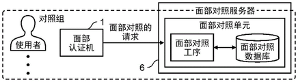
Next, the face matching means will be described. Fig. 5A, 5B, and 5C are explanatory diagrams showing an outline of the face collation unit.
A plurality of face collation units for performing face collation can be provided in the face collation server 6. The face collation unit has a face collation process for executing a face collation program and a face collation database in which information (face feature amount data) of a user as a comparison target of face collation is registered.
The face collation unit is provided for each collation group, and performs face collation in response to a request for face collation from the face authentication machine 1 belonging to the collation group. Therefore, a plurality of matching groups can be handled by one face matching server 6.
Here, the face authentication device 1 holds the network address (IP address) of the face verification server 6 as verification group information, and can perform an inquiry of face verification for the face verification server 6 corresponding to the own device based on the network address. In the present embodiment, the face authentication device 1 holds a network address (IP address) for each face verification unit, and can inquire about the face verification unit corresponding to the device based on the network address.
In addition, since the face collation database is provided for each collation group, the facial feature data of the user can be stored in units of collation groups. The face matching step is for performing matching processing between the face feature data stored in units of groups and the face feature data generated from the face image data acquired from the face authentication device 1 of the same group.
Here, there are various ways of correspondence between the face authentication device 1 and the face collation unit.
In the example shown in fig. 5A, in the face collation server 6, 1 face collation unit of the collation group to which the face authentication machine 1 belongs is provided, and the face authentication machines 1 are in one-to-one correspondence with the face collation server 6.
In the example shown in fig. 5B, the face authentication machines 1 correspond to the face collation servers 6 one by one, but in the face collation server 6, 2 face collation units of the collation group to which the face authentication machines 1 belong are provided. In this case, in the case of the face authentication device 1 installed in the entrance of a multi-tenant building, information of users (for example, user a and user B) belonging to different organizations can be managed by different collation databases.
In the example shown in fig. 5C, the face authentication device 1 corresponds to the face verification server 6 in a 1-to-2 manner, and the face authentication device 1 makes an inquiry of face verification (request for verification by the user) to both face verification servers 6. In this case, by providing two or more identical face comparison units in different face comparison servers 6, that is, by providing face comparison units that perform face comparison using the face feature data of the same user, it is possible to achieve the distribution of the burden and the handling of death (japanese: alive.
Next, a schematic configuration of the face authentication device 1 will be described. Fig. 6 is a block diagram showing the schematic configuration of the face authentication machine 1.
The face authentication device 1 includes a camera 11 (face image acquisition unit), a display 12 (display unit), a communication unit 13 (transmission unit, reception unit), a storage unit 14, a control unit 15, and a control signal transmission unit 17.
The camera 11 always captures a predetermined image capture area, and if a person enters the image capture area, it is possible to capture the person and acquire a captured image of a person to be subjected to face authentication (including a registered user). In addition, in order to save power, a human detection sensor (not shown) may be provided, and the camera 11 may be activated after the arrival of a human is detected.
The display 12 displays the progress status of the face authentication and the face authentication result, so that the person who accepts the face authentication can confirm the progress status of the face authentication and the face authentication result. Further, a speaker may be provided as an output unit for outputting the authentication result of the target person, and the face authentication result may be notified by voice. The display 12 can be omitted depending on the installation location of the face authentication machine 1 (for example, in the case where the face authentication machine 1 is installed in a security gate).
The communication unit 13 communicates with the face collation server 6 via a network. In the present embodiment, the face image data is transmitted to the face collation server 6. In addition, the authentication result of the user is received from the face collation server 6. The communication unit 13 communicates with the face management server 5 via a network. In the present embodiment, the face management server 5 receives the collation information and the like.
The storage unit 14 stores data of a photographed image (face image) of a user, collation group information, a control program executed by a processor constituting the control unit 15, and the like.
The control unit 15 includes an activation processing unit 21, a face image extraction unit 22, a face matching request unit 23, an authentication result notification unit 24, an authentication result adjustment unit 25 (history information generation unit), and an operation status monitoring unit 26. The control unit 15 is configured by a processor, and each unit of the control unit 15 is realized by the processor executing a program stored in the storage unit 14.
The activation processing unit 21 acquires the collation information from the face management server 5 and stores the collation information in the storage unit 14 when the face authentication device 1 is activated. The acquisition of the collation information is not limited to this, and the collation information may be issued from the face management server 5 to the target face authentication machine 1 in association with update of the collation information or the like.
The face image extraction unit 22 can acquire a photographed image of a subject person subjected to face authentication from the camera 11 (camera image capture), detect a face of a person from the photographed image (face detection), determine whether the size of the detected face is appropriate (face size check), and cut out a face region from the photographed image (face cutout), thereby acquiring data of a face image of the subject person (face image for authentication). The face image data may be data of only an image of a face region, but may be a combination of data of a photographed image (an image of a predetermined photographing region) and position information (face frame information) of the face region on the data of the photographed image.
The face collation request unit 23 transmits a request for face collation to the face collation server 6 of the collation group matching the own apparatus by using the communication unit 23.
The authentication result notification unit 24 notifies the user of the face authentication result by displaying the face authentication result acquired from the face verification server 6 by the communication unit 23 on the display 12.
The authentication result adjustment unit 25 performs control for cooperating with the external device 16 based on the face verification result of the user acquired from the face verification server 6. As the external device 16, for example, a gate device (see fig. 2) that manages the passage of a user through a facility, a lock device for a door that manages entrance or exit into or out of a conference room or a predetermined area in the facility, a settlement terminal device for a user to pay for services or purchased products received in the facility, and the like can be used. Further, the authentication result adjusting unit 25 can generate information of an entry history in which a plurality of users entering the conference room are associated with each other in cooperation with the locking device of the door of the conference room.
The face authentication device 1 and the external device 16 are directly connected by a communication cable or the like, or are connected so as to be able to communicate via a known network. The authentication result adjusting unit 25 is configured by a connection application, and can thereby notify the server or the like of the external system including the external device 16 of the face verification result of the user.
The operation status monitoring unit 26 monitors the operation status of the own device and notifies the operation status of the own device to the face management server 5.
The control signal transmitting unit 17 transmits a control signal for controlling the operation thereof to the external device 16.
Next, the management terminal 2 will be explained. Fig. 7 is a block diagram showing a schematic configuration of the management terminal 2.
The management terminal 2 includes a communication unit 31, a display 32 (display unit), an input device 33 (operation unit), a storage unit 34, and a control unit 35.
The communication unit 31 communicates with the face management server 5 via a network. In the present embodiment, screen information and the like are received from the face management server 5, and operation information and the like of the administrator corresponding to the screen information and the like are transmitted to the face management server 5.
The display 32 displays various screens. The input device 33 is a mouse, a keyboard, or the like, and operates a screen displayed on the display 32.
The storage unit 34 stores a program (management application) executed by a processor constituting the control unit 35, and the like.
The control unit 35 includes a GUI (graphical user interface) control unit 38. The control unit 35 is configured by a processor, and each unit of the control unit 35 is realized by the processor executing a program (management application) stored in the storage unit 34.
The GUI control unit 38 displays various operation screens issued from the face management server 5 on the display 32. In addition, input information is acquired in response to an input operation by the administrator using the input device 33, and screen control is performed. In the present embodiment, the GUI control section 38 performs display input control on a screen related to login, specifically, a login screen. The GUI control unit 38 performs display input control on a screen related to user management, specifically, a screen related to registration (individual registration, batch registration), reference, update, and deletion of information related to the user. The GUI control unit 38 performs display input control on a screen related to the control group management, specifically, a screen related to registration (individual registration, batch registration), reference, update, and deletion with respect to the control group. The GUI control unit 38 performs display input control on a screen related to the management of the authentication machine, specifically, a screen related to registration, reference, update, and deletion of the association between the authentication machine and the collation. The GUI control unit 38 performs display input control on a reference screen of an authentication log (history information of face authentication).
Next, a schematic configuration of the registration apparatus 4 will be described. Fig. 8 is a block diagram showing a schematic configuration of the registration apparatus 4.
The registration device 4 includes a camera 41A for taking a picture of a face, a camera 41B (personal information acquisition unit) for acquiring information, a display 42 (display unit), a communication unit 43, a storage unit 44, and a control unit 45.
The camera 41A for taking a picture of the face can take a picture of the user by taking a picture of the face of the user at a reception place near a facility, for example.
The camera 41B for information acquisition can acquire a photographed image of a business card by photographing the business card shown by the user. However, the camera 41B for acquiring information may capture an image of a user's portable article (for example, a card for settlement of the user, a card on which information of a user's destination is recorded, or the like) on which information that can identify the user is displayed, and acquire the captured image. The registration apparatus 4 can be provided with a mounting table (mounting surface) 116 (see fig. 14C) for allowing a user to easily place a business card or the like in the imaging area of the camera 41B, so that the camera 41B for acquiring information can reliably perform imaging.
In the registration device 4, the cameras 41A and 41B for face photographing and information acquisition may be configured by one camera. Further, the shooting times of the camera 41A for face shooting and the camera 41B for information acquisition can be determined by the user's operation (for example, pressing a shooting button) on the registration device 4. Alternatively, the imaging time may be determined by a reception person in charge of the facility.
Further, an information reading device (e.g., an RFID reader) capable of reading the user's identification information from an information recording medium (e.g., an RFID tag) held by the user by wireless communication can also be provided in the registration device 4.
The display 42 can display the registration procedure of the authentication information (including the personal information of the user) to the user (see fig. 14 (a) to (F)). Further, the display 42 may be provided with a speaker to notify the user of the registration process by voice. Further, by configuring the display 42 with a touch panel, information input by a user through a touch operation can be acquired.
The communication unit 43 communicates with the face management server 5 via a network. In the present embodiment, the face image data and the specification information are transmitted to the face management server 5.
The storage unit 44 stores data of a photographed image (face image) of the user, user identification information, a control program executed by a processor constituting the control unit 45, and the like.
The control unit 45 includes a face image extracting unit 46, a specifying information acquiring unit 47, a registration requesting unit 48, a GUI control unit 49, and an operation status monitoring unit 50. The control unit 45 is configured by a processor, and each unit of the control unit 45 is realized by the processor executing a program stored in the storage unit 44.
The facial image extracting unit 46 can acquire a photographed image of the subject person whose face is to be authenticated from the camera 41A for photographing the face, detect the face of the person from the photographed image, and determine whether or not the facial image of the user is appropriately acquired. In addition, when the acquired face image is not appropriate, the face image extracting unit 46 can cause the display 42 to display a message urging the user to take the image again. The face image extracting unit 46 may have functions of camera image capturing, face detection, face size check, and face cropping, as in the face image extracting unit 22 of the face authentication machine 1 described above.
The specific information acquiring unit 47 has an OCR (optical character recognition) function, and generates specific information (here, business card description information) from characters, symbols, and the like extracted from the captured image of the camera 41B for information acquisition.
The registration requesting unit 48 transmits a request for registering the user to the face management server 5 by using the communication unit 43.
The GUI control unit 49 displays various guide screens for the user, which are distributed from the face management server 5, on the display 42. In addition, input information is acquired in response to an input operation performed by the user using an input function of the display 42 (here, a touch panel), and screen control is performed.
The operation status monitoring unit 50 monitors the operation status of the own device, and notifies the operation status of the own device to the face management server 5.
Next, a schematic configuration of the face management server 5 will be described. Fig. 9 is a block diagram showing the schematic configuration of the face management server 5.
The face management server 5 includes a communication unit 51, a storage unit 52, and a control unit 53.
The communication unit 51 communicates with the management terminal 2 via a network. The communication unit 51 communicates with the face authentication device 1 via a network. The communication unit 51 communicates with the registration apparatus 4. The communication unit 51 communicates with the face collation server 6.
The storage unit 52 stores a face information database, a database related to the related information between the face authentication machine 1 and the collation group, a database related to the related information between the face collation server 6 and the collation group, a manager access log, a control program executed by a processor constituting the control unit 53, and the like.
The face information database stores face images for registration as information on each registered user. In addition, in the face information database, identification information of each user is stored in association with a face image for registration. In addition, a collation group or the like is registered in the face information database. In addition, the face image of the user and the identification information may also be stored in an encrypted state to protect privacy. Further, the face information database may store the face image of the user and a part of the identification information in a state of being replaced with anonymized information.
The control unit 53 includes a manager access management unit 61, a user management unit 62, a comparison group management unit 63, a device management unit 64, a face comparison server management unit 65, a face information management unit 66, a database management unit 67, an operation status monitoring unit 68, an authentication log presentation unit 69, an encryption unit 70, an anonymization information generation unit 80, and an image generation unit 90. The control unit 53 is configured by a processor, and each unit of the control unit 53 is realized by the processor executing a program stored in the storage unit 52. Each unit of the control unit 53 is configured as a WebAPI (Web Application Programming Interface).
The administrator access management unit 61 permits or denies access (login) by an administrator of the device according to the access authority of the administrator who accesses the device from the management terminal 2. The administrator access management unit 61 monitors the status of access (login) from the management terminal 2 to the face management server 5 and the face collation server 6, and when an access from the management terminal 2 is detected, records information related to the access (an administrator who has made the access, the date and time, and the like) as an administrator access log (history information). Thus, the face management server 5 provides the administrator access log to the management terminal 2 in response to a request from the management terminal 2 to refer to the administrator access log, so that the administrator can browse the administrator access log.
The administrator access management unit 61 manages access from the management terminal 2 to the device itself, and when the administrator operates the management terminal 2 to access the device itself, information at that time is stored in the storage unit 52 as an administrator access log (history information). In addition, the administrator access log is presented to the management terminal 2 in response to a reference request from the management terminal 2.
The user management unit 62 manages information related to the user, such as a face image for registration and identification information, and performs necessary processing related to the user in response to a request from the management terminal 2. In the present embodiment, the management terminal 2 requests registration, reference, update, and deletion of the user, and the user management unit 62 performs necessary processing in response to the request. The user management unit 62 manages information on a conference in which the user is present and information on the personal relationship of the user.
The collation management unit 63 manages information on a collation, and performs necessary processing on the collation in response to a request from the management terminal 2. In the present embodiment, the management terminal 2 requests registration, reference, update, and deletion of the control group, and performs necessary processing in response to the request. Further, collation group information, that is, information necessary for the face authentication machine 1 to request the face collation server 6 matching its own collation group to the face authentication machine 1 is generated for each face authentication machine 1, and the collation group information is supplied to the face authentication machine 1.
The device management unit 64 manages information relating to the face authentication device 1 and the registration apparatus 4, and performs necessary processing relating to the face authentication device 1 and the registration apparatus 4 in response to a request from the management terminal 2. In the present embodiment, the management terminal 2 requests registration, reference, update, and deletion of the association between the face authentication machine 1 and the collation group, and performs necessary processing in response to the request.
The face collation server management section 65 manages information about the face collation server 6, and performs necessary processing about the face collation server 6 in response to a request from the management terminal 2. In the present embodiment, a request for registration, reference, and deletion is made from the management terminal 2 regarding the association between the face collation server 6 and the collation group, and necessary processing is performed in response to the request.
The face information management unit 66 synchronizes the face information of the user (such as a face image and identification information) stored in the present apparatus with the face information of the user (such as face feature data of the user) stored in the face collation server 6. The face information management unit 66 copies face information (face feature data of the user).
The database management unit 67 manages the database provided in the present apparatus, and performs backup and restoration of the database.
The operation status monitoring unit 68 monitors the operation status of the device itself, receives notification of the operation status from the face authentication machine 1, the registration device 4, and the face collation server 6, and displays the operation status of the face authentication machine 1, the registration device 4, the device itself (the face management server 5), and the face collation server 6 on the management terminal 2 in a screen format in response to an operation by the administrator using the management terminal 2.
The authentication log presenting section 69 acquires the authentication log from the face collation server 6 in response to the reference request from the management terminal 2, and presents the authentication log in the management terminal 2.
The encryption section 70 can perform encryption processing on at least a part of the face image of the user and the identification information. The encrypted information is stored in the storage unit 52. The face management server 5 may delete original information (information before encryption processing) corresponding to the information encrypted by the encryption unit 70 from the storage unit 52.
The anonymization information generating unit 80 can perform a process of anonymizing at least a part of the face image of the user and the identification information. As the anonymization processing, the anonymization information generating section 80 can replace a part of the face image and the identification information of the user with the dummy information, for example. In the anonymization processing, the dummy information may be used as information missing from the face image of the user and the identification information (for example, information which is rejected from the user). The anonymized information is stored in the storage unit 52. The encryption unit 70 may encrypt only the original information (information before the anonymization process) corresponding to the information anonymized by the anonymized information generating unit 80.
The image generating unit 90 generates a management screen for the manager to confirm or change the management state of the information management by the user management unit 62 and the device management unit 64. The management screen is distributed to the management terminal 2 and the like.
Next, a schematic configuration of the face collation server 6 will be described. Fig. 10 is a block diagram showing a schematic configuration of the face collation server 6.
The face collation server 6 includes a communication unit 71, a storage unit 72, and a control unit 73.
The communication unit 71 communicates with the face authentication machine 1 via a network. In the present embodiment, face image data and the like are received from the face authentication device 1. Further, the authentication result of the user and the like are transmitted to the face authentication machine 1. The communication unit 71 communicates with the face management server 5 via a network. In the present embodiment, requests for various processes and the like are received from the face management server 5, and responses and the like corresponding thereto are transmitted to the face management server 5.
The storage unit 72 stores a face matching database, association information between a user and feature values, information on a matching group of the present apparatus, an authentication log, a control program executed by a processor constituting the control unit 73, and the like.
The facial feature amount data of the user and the like are registered in the facial matching database as information on each registered user. The face comparison database is provided for each comparison group, and stores the facial feature data of the user in units of groups. Here, the registered user's facial feature amount data may also be backed up and saved to a nonvolatile memory such as an HDD, SSD, or the like provided in the face collation server 6 in case of disappearing unexpectedly from the face collation database.
The control unit 73 includes a comparison group management unit 81, an image quality inspection unit 82, a face image extraction unit 83, a face feature generation unit 84, a face feature management unit 85, a face feature comparison unit 86, an authentication log management unit 87, a database management unit 88, and an operation status monitoring unit 89. The control unit 73 is configured by a processor, and each unit of the control unit 73 is realized by the processor executing a program stored in the storage unit 72. Each unit of the control unit 73 is configured as a Web API.
The collation management unit 81 manages a collation to which the own apparatus belongs, and performs registration and deletion processing on the collation in response to a request from the face management server 5.
The image quality inspection unit 82 determines whether or not the image of the face region in the captured image satisfies a predetermined quality. Specifically, the presence or absence of wearing a mask and the presence or absence of wearing sunglasses are detected from the image as the subject, and the face authentication matching degree (evaluation value obtained based on the orientation and expression of the face) is calculated.
When the user is registered, the face image extraction unit 83 extracts a face image from the photographed image of the user acquired by the registration device 4. At this time, the face image extracting unit 83 detects a face of a person from the captured image (face detection) as necessary, determines whether the size of the detected face is appropriate (face size check), and cuts out a face region from the captured image (face cut), thereby acquiring a face image of the person. In addition, the face image extraction unit 83 can also extract a face image from the captured image of the subject person acquired by the face authentication device 1 at the time of face authentication.
When the user is registered and when the face is authenticated, the face feature amount generation unit 84 detects face feature points from data of the face image for registration and the face image for authentication, and generates face feature amount data.
When registering the user, the facial feature amount management unit 85 registers the facial feature amount data of the user generated by the facial feature amount generation unit 84 in the facial matching database corresponding to the matching group of the user. In addition, when updating or deleting is performed, the face feature amount data registered in the face collation database is deleted in response to a request from the face management server 5. In addition, in the case where the version upgrade of the program related to the algorithm of the face feature amount generation or the face collation is performed, the face feature amount data registered in the face collation database is updated in response to a request from the face management server 5 so as to correspond to the new program.
In the face authentication, the face feature amount comparing unit 86 compares the face feature amount data of the subject person generated from the data of the authentication face image acquired from the face authentication device 1 with the face feature amount data of the registered person (registered user) stored in the present apparatus, and determines whether or not the subject person is a registered person. The facial feature quantity matching unit 86 is a facial feature quantity matching unit corresponding to a matching group associated with the own apparatus, and when a plurality of matching groups are associated with the own apparatus, a plurality of facial feature quantity matching units 86 for the respective matching groups are provided. The facial feature quantity matching unit 86 (face matching step) is combined with a face matching database to constitute face matching means.
The facial feature quantity collation unit 86 calculates the degree of similarity (collation score) between the subject person and the registered person. By comparing the similarity with a predetermined threshold, it is possible to determine whether the face authentication has succeeded or not. In addition to notifying the face authentication machine 1 of the result of the determination as to whether or not the person is successful as the comparison result, the face authentication machine 1 may be notified of the person ID or the degree of similarity related to the registered person having a high degree of similarity as the comparison result.
When a request for face authentication is made from the face authentication device 1 to the present apparatus, the authentication log management unit 87 stores information at that time, that is, information such as the device ID of the face authentication device 1 that is the source of the request for face authentication, and the face verification result, in the storage unit 72 as an authentication log. In addition, the authentication log is provided to the face management server 5 in response to a request from the face management server 5.
The database management unit 88 manages the database provided in the present apparatus, and performs backup and restoration of the database.
The operation status monitoring unit 89 monitors the operation status of the own device and notifies the operation status of the own device to the face management server 5.
In the present embodiment, the face collation server 6 has the respective functions of face image extraction, face feature amount generation, and face feature amount collation as the main functions, but these functions can be configured in another information processing apparatus independent of each other. For example, the function of extracting a face image may be configured in another information processing apparatus independent of other functions such as face feature amount generation and face feature amount collation.
Next, a schematic configuration of the external device 16 will be described. Fig. 11 is a block diagram showing a schematic configuration of the external device 16.
The external device 16 includes a control signal receiving unit 91, a driving unit 92, a power supply unit 93, and a control unit 94.
The control signal receiving unit 91 receives a control signal (an operation command from the face authentication device 1 cooperating with the external device 16) transmitted from the control signal transmitting unit 17 of the face authentication device 1.
The driving unit 92 is controlled by the control unit 94 based on a control signal from the face authentication machine 1. For example, in the case where the external device 16 is a shutter device, the driving unit 92 supplies power for opening (or closing) an opening/closing door portion of the shutter device. In addition, when the external device 16 is a door lock device, the driving unit 92 supplies power for locking (or unlocking) the lock device. In the case where a device (for example, a settlement terminal device) for driving the external device 16 is not provided, the driving unit 92 can be omitted.
The power supply unit 93 supplies power to each unit of the external device 16. The power supply unit 93 is electrically connected to the power supply unit 97 of the face authentication device 1, and can supply power to the power supply unit 97 as well. The power supply unit 97 supplies power to each unit of the face authentication device 1. Power supply unit 97 is connected to Power supply unit 97 of face authentication device 1 via a LAN (Local Area Network) cable, and Power can be supplied to Power supply unit 97 by PoE (Power over Ethernet).
The power supply unit 93 can receive power supply from an uninterruptible power supply device (or an emergency power supply) independent of the power supply line of the entire facility. This allows the gate device as the external device 16 to operate normally even when a power failure occurs in the facility, for example, and has an advantage that the safety of the facility can be maintained.
The control unit 94 controls the operations of the respective units of the external device 16. The control unit 94 can execute processing necessary for the external device 16. The control unit 94 is configured by a processor, and is realized by the processor executing a program stored in a storage unit (memory), not shown.
Next, the face image extraction process will be described. Fig. 12 is an explanatory diagram showing an outline of the face image extraction processing.
As described above, the face image extracting unit 22 of the face authentication device 1 performs the processing of generating the face image data from the photographed image data of the user by the face image extracting processing, that is, the processing of face detection, face size check, and face clipping, but the face image extracting processing can be similarly performed by the face image extracting unit 83 of the face collation server 6.
When the user is registered, the data of the photographed image of the user is transmitted from the registration device 4 to the face verification server 6 via the face management server 5, and the face image extraction unit 83 of the face verification server 6 performs face image extraction processing. In some cases, the data of the photographed image of the user may be transmitted from the management terminal 2 to the face verification server 6 via the face management server 5.
On the other hand, in the face authentication, the face image extraction process may be performed only in the face authentication device 1, and the face image extraction process may not be performed in the face verification server 6. In this case, a highly accurate face detection function is provided to the face authentication device 1. The face authentication device 1 always takes a picture of the image pickup area by the camera 11, and transmits face image information (the image pickup image data and the face frame information) to the face verification server 6 when a face is detected. This distributes the load of the face image extraction process to the plurality of face authentication machines 1, and can reduce the load on the face verification server 6. In addition, since the reduction of the traffic volume can be achieved, the load on the network can be reduced. Furthermore, since the response of the face authentication can be performed at high speed, the face authentication of the target person appearing in sequence can be performed efficiently.
That is, the face authentication processing of the user is shared by the face authentication machine 1 and the face collation server 6, and thus it is not necessary to provide a plurality of expensive authentication machines in which all the face authentication processing of the user is concentrated on the face authentication machine 1 as in the conventional case. Even if the face feature data is updated, the face verification server 6 may perform the operation without requiring a large-scale maintenance operation on the authentication machine. Therefore, according to the present embodiment, it is possible to construct a face authentication system having an inexpensive configuration and excellent workability.
However, the face authentication device 1 may not have the function of extracting the face image, that is, the face authentication device 1 may not be provided with the face image extracting unit 22.
Fig. 13 is an explanatory diagram showing an outline of an inquiry of face authentication based on the comparison group information.
The face management server 5 holds information on a collation group to which the user belongs, association information between the face authentication machine 1 and the collation group, and association information between the face collation server 6 and the collation group. In addition, the collation information for each face authentication machine 1 is generated in the collation management section 63 of the face management server 5 based on the association information between the face authentication machine 1 and the collation and the association information between the face collation server 6 and the collation.
This collation information is information necessary for the face authentication machine 1 to request face authentication from the face collation server 6 that matches its own collation. The matching group information includes identification information (group number) of a matching group to which the face authentication device 1 belongs, and destination information of the face matching server 6 to which face authentication is requested from the face authentication device 1, that is, the face matching server 6 corresponding to the matching group of the face authentication device 1. Here, the destination information is specifically a network address (for example, an IP address) of the face collation server 6, and the face collation server 6 as the request destination of the face authentication is determined based on the destination information, and the face authentication machine 1 is associated with the face collation server 6 as the request destination of the face authentication. When the face authentication device 1 belongs to a plurality of collation groups, the collation group information includes addresses (IP addresses) of the corresponding plurality of face collation servers 6.
In the face authentication device 1, the activation processing unit 21 acquires the collation information from the face management server 5 as the operation setting information at the time of activation or the like, and stores it in the own device. In the face authentication device 1, when the face of a person is detected, a request for face collation is transmitted to the face collation server 6 that matches the collation group to which the device belongs. The request for face matching includes information on a matching group to which the device belongs.
In addition, in the face authentication device 1, the setting information on the collation information and the like may be acquired from the face management server 5 at a predetermined time or periodically at a predetermined interval, or the collation information may be issued from the face management server 5, in addition to the start-up time.
The face collation server 6 holds the association information between the face collation process of the present apparatus and the collation group. In the face collation server 6, when a request for face authentication is received from the face authentication machine 1, a face authentication process corresponding to the face authentication machine 1 is determined based on the association information between the collation group and the face authentication process and the collation group acquired from the face authentication machine 1, and face collation is performed in the face authentication process. Thus, the face matching process is performed in the face authentication step corresponding to the designated matching group.
In the present embodiment, the face collation server 6 is provided with a face collation database for each collation group, and stores face feature amount data in units of collation groups. Therefore, in the face collation, the face feature amount data registered in the face collation database corresponding to the collation group of the face authentication device 1 may be used as the target to perform the face collation. On the other hand, the face verification server 6 may perform verification regardless of the verification group of the face authentication device 1 and then perform screening of the verification result. That is, after the face comparison is performed for the face feature data of all users stored in the face comparison server 6, only the comparison result with the user belonging to the comparison group of the face authentication machine 1 may be extracted. In this case, the face comparison database may not be separately provided for each comparison component.
Next, a registration operation performed by the user in the registration apparatus 4 will be described. Fig. 14 is an explanatory diagram showing an example of a registration screen displayed in the registration device 4.
When the user starts using the facility (or does not access the facility again within a predetermined period after registration), the registration device 4 can perform a registration operation for authentication. In the present embodiment, the user can perform a registration operation in accordance with a guide screen displayed on the display 42 (here, a touch panel) of the registration device 4. Further, a part of the registration operation for authentication (such as pressing of a button) described below may be performed by the recipient who has received the user's consent.
An initial screen is displayed on the display 42 of the registration device 4, and a registration start button 101 is displayed on the initial screen (see fig. 14 a). Therefore, when the user presses (touches) the registration start button 101, a description about the processing of personal information in the face authentication system and a screen for soliciting user consent are displayed (see fig. 14 (B)).
The user can agree with the processing of the personal information in the face authentication system by pressing the consent button 102 on the screen of fig. 14 (B). Thereby, the registration apparatus 4 starts acquiring the authentication information of the user. Therefore, a screen (first screen) indicating a method of acquiring the identification information for identifying the user is displayed on the display 42 (see fig. 14C). Further, the user can stop the registration operation by pressing the stop button 103. In addition, the user does not need to approve the screen, and the screen for requesting the approval of the user can be omitted. Alternatively, the approval may be replaced by an operation of the photographing button 104, the photographing button 107, and the registration button 111, which will be described later. In addition, the agreement may be obtained by a predetermined procedure before the registration device 4 is used.
In the example shown in fig. 14C, a screen (first screen) showing a method of capturing the user's business card (here, guidance for placing the user's business card in the imaging area of the information acquisition camera 41B) is displayed. Therefore, when the user places the business card on the placement table 116 of the registration apparatus 4 and presses the photographing button 104, photographing of the business card is performed by the registration apparatus 4. Further, the user can stop the photographing of the business card by pressing the stop button 105.
When the photographing of the business card is completed, a screen (first screen) showing a method of photographing the face image for registration of the user (guidance for positioning the face of the user within the photographing region of the face photographing camera 41A) is displayed next in the registration device 4 (see fig. 14D). At this time, the registration device 4 can prompt the user to align the face by blinking the photographing frame 106 corresponding to the photographing region. A live image (live moving image) captured by the face camera 41A is displayed in the camera frame 106. Therefore, when the user positions his or her face in the photographing frame and presses the photographing button 107, photographing of the user's face is performed by the registration device 4. At this time, the registration device 4 can generate a shutter sound when the photographing button 107 is pressed. Further, the user can stop the photographing of the face by pressing the stop button 108.
When the photographing of the face is completed, a screen (first screen) for the user to confirm the photographed face image is displayed next in the registration device 4 (see fig. 14 (E)). The captured face image (still image) is displayed on the screen, and the user presses the registration button 111 if the user determines that there is no problem with the captured face image. On the other hand, when the user determines that there is a problem with the captured face image, the user can press the re-photographing button 112. Thereby, the screen shown in (D) of fig. 14 is displayed on the registration device 4, and the face can be re-photographed. Further, the user can stop the photographing of the face by pressing the stop button 113.
When photographing of the face is finished, the acquired face image and the specification information (here, the business card image and the business card description information extracted from the business card image by OCR) are transmitted to the face management server 5. In this case, for a user who does not want to provide both the face image and the business card image at the same time, at least one of the face image and the business card image may be transmitted to the face management server 5. Thereby, the face management server 5 executes registration processing relating to the user (see fig. 15). When the registration process of the face management server 5 is normally completed, a screen (second screen) indicating that the registration is completed is displayed in the registration device 4 (see fig. 14 (F) and fig. 15, "display the processing result in the form of a screen"). At this time, the user presses the end button 115, and the registration operation in the registration device 4 is ended. Further, the order of acquisition of the face image and the business card image may be reversed.
After the registration operation is finished, the registration apparatus 4 can delete the face image, the identification information, stored in the storage section 44. This can prevent personal information from being stored in the registration device 4 used by an unspecified person for a long period of time, and can manage personal information of the user more securely.
In place of the registration by the user using the registration device 4, the administrator can use the management terminal 2 to perform registration with respect to the user after preparing a file of a face image for registration of the user in advance. In order to supplement the registration by the registration device 4, the administrator can also perform correction of the authentication information registered by the registration device 4 and addition of new information from the management terminal 2.
Next, a user-related registration process executed in response to the user registration operation described above will be described. Fig. 15 is a sequence diagram showing a procedure of the registration processing relating to the user.
When the registration operation of the user is performed in the registration device 4 as described above, the face management server 5 starts the registration process related to the user as shown in fig. 15. At this time, the face management server 5 receives the operation information of the user from the registration device 4, and also receives the photographed image of the face and the specifying information. In this registration processing, first, the face management server 5 transmits a request for extracting a face image to the face collation server 6 of the collation group that matches the user as the target. The request includes a photographed image of the face of the user acquired from the registration device 4. At this time, when there are a plurality of face collation servers 6 of the collation group matching the target user, one face collation server 6 is selected, and a request for extracting a face image is transmitted to the one face collation server 6.
The face collation server 6 performs face image extraction processing upon receiving a request for extracting a face image from the face management server 5. In the face image extraction process, the photographed image of the face of the user acquired from the face management server 5 is subjected to processes such as face detection and face clipping to extract the face image of the user. Then, a response to extract the face image is sent to the face management server 5. The response contains an image of the user's face.
The face management server 5, upon receiving a response to extract a face image from the face collation server 6, transmits a request to register a face to the face collation server 6 of the collation group matching the user as the target. The request can include the face image of the user acquired from the specific face collation server 6. At this time, when there are a plurality of face collation servers 6 of the collation group that matches the target user, a request for registering a face is transmitted to all (two in fig. 15) face collation servers 6 so as to include the face image of the user acquired from the specific face collation server 6.
In addition, the face management server 5 may omit the request for extracting the face image to be issued to the face verification server 6, and add the captured image of the face of the user acquired from the registration device 4 together with the operation information to the request for registering the face to be issued to the face verification server 6.
The face collation server 6 performs face registration processing upon receiving a request for registering a face from the face management server 5. In the face registration processing, a face feature amount is generated from a face image of a user, and the face feature amount is registered in a database. At this time, the face registration ID is given in association with the facial feature amount of the user. Then, a response to register the face is transmitted to the face management server 5. The response includes a result indicating whether or not the face registration has ended normally, and a face registration ID. Further, with the completion of the registration of the facial feature quantity in the database, the face image of the user in the face collation server 6 is deleted. The data of the facial feature amount may be backed up and stored in a nonvolatile memory such as a Hard Disk Drive (HDD) or a Solid State Drive (SSD) managed separately from the facial matching database of the facial matching server 6.
The face management server 5 performs registration processing related to the user when a response to register a face is received from the face collation server 6 and the processing has ended normally. In this registration process, the face image of the user acquired from the registration device 4 is registered in the face information database. In addition, the face management server 5 registers the identification information of the user acquired from the face collation server 6 in the face information database in association with the face image. The face management server 5 registers the face registration ID issued by the face collation server 6 in the face information database as the user's information.
Next, a process of face authentication of the user in the face authentication machine 1 will be described. Fig. 16 shows a first example of the process of face authentication relating to a user. Here, an example is shown in which a gate device (security gate) for managing the passage of a user is used as the external device 16 cooperating with the face authentication machine 1.
The face authentication device 1 transmits a request for face matching to the face matching server 6 when a face of a person is detected from a captured image of the camera 11 and a face image is acquired. The request for face collation includes the device ID of the face authentication device 1 as the request source, the collation group of the face authentication device 1, data of the photographed image (face image for authentication) of the subject of face authentication, face frame information, and collation conditions.
When receiving the request for the face matching, the face matching server 6 first generates the face feature amount of the target person from the face image of the target person acquired from the face authentication device 1 by the face feature amount generation unit 84. Next, the facial feature amount of the target person is compared with the facial feature amount of the user registered in the facial authentication database in the facial feature amount comparison unit 86 of the facial authentication unit corresponding to the comparison group of the facial authentication machine 1. At this time, the face matching process is performed in the face authentication step of the matching group matching the face authentication device 1 as the request source. When the face collation process ends, the face collation server 6 transmits a response of face collation to the face authentication machine 1 as a request source. The response of the face control includes a control result (success, failure), a control score, and a user code.
The facial feature quantity matching unit 86 calculates a matching score indicating the degree of similarity between the target person of face authentication and the registered user, and when the matching score is equal to or greater than a predetermined reference value, generates a matching result indicating that face matching is successful, assuming that the target person of face authentication is the registered user himself/herself. On the other hand, when the comparison scores of all users are not equal to or greater than the reference value, it is determined that the target person for face authentication is not a registered user, and a comparison result indicating that face comparison has failed is generated.
Further, the processing conditions for face collation (parameters for face collation) performed in the face collation server 6 may be added to the request for collation. This allows the face authentication device 1 to instruct the face verification server 6 to perform the face verification process. For example, a threshold value related to the comparison score is specified as a processing condition for face comparison, and a comparison result in which the comparison score is equal to or greater than a predetermined threshold value is included in the response. In addition, the number of comparison results is specified as a processing condition for face comparison, and a predetermined number of comparison results with high to low comparison scores are included in the response.
In the face collation server 6, when the face collation is completed, the authentication log management unit 87 stores information such as the collation result acquired by the face collation in the database as an authentication log (history information of face authentication). In this case, the result of face authentication (success or failure) may be stored as an authentication log, and the matching score may be included in the authentication log. Further, the authentication log may include the face image of the target person acquired from the face authentication device 1. In this case, the face image of the subject person may be encrypted and stored.
In addition, when a plurality of valid comparison results whose comparison scores exceed the threshold value are obtained, a predetermined number of comparison results whose comparison scores are high to low may be locked and stored as an authentication log. In addition, when the face collation is not normally completed or a valid collation result in which the collation score exceeds the threshold value is not obtained, only the information included in the request from the face authentication device 1 may be stored as the authentication log.
When receiving a response indicating face verification that face verification has succeeded from the face verification server 6, the face verification apparatus 1 transmits an opening/closing control signal for opening/closing the door section of the shutter apparatus to the shutter apparatus cooperating with the face verification apparatus 1. That is, the face authentication device 1 functions as a control device (shutter opening/closing control device) that controls the operation of the opening/closing door section of the shutter device cooperating with the face authentication device 1 by converting the response of the face check into an opening/closing control signal for the opening/closing door section. Thus, the shutter device performs an operation of opening the opening/closing door section (i.e., allowing a user to pass) by the driving section 92. The face authentication device 1 deletes the face image of the user stored in the storage unit 14 in response to completion of transmission of the control signal (open/close control signal). Here, the response of the face check is converted into an open/close control signal for the open/close door unit, but when the open/close control for the open/close door unit of the gate device is performed by an entry/exit management system constructed as an external system, the control signal is transmitted to the entry/exit management system so that the face authentication result is reflected in the open/close control for the gate device.
Fig. 17 shows a second example of the process of face authentication relating to a user. Fig. 18A, 18B, and 18C are explanatory views showing an example of an authentication screen (screen at the time of authentication) displayed in the face authentication machine 1. Here, an example is shown in which a lock device provided on a door of a conference room is used as the external device 16 that cooperates with the face authentication machine 1. In the second example of the face authentication process, the details of the same matters as in the first example described above are omitted.
The face authentication machine 1 is provided on a wall of a corridor facing a conference room, for example. When the proximity of a person is sensed (that is, the user is detected) by the person detection sensor or the like, the face authentication device 1 displays a standby screen (initial screen) of the authentication screen on the display 12 (see fig. 18A). Here, the authentication screen (notification screen) displayed on the display 12 includes an image display area 121 for displaying a live image (live moving image) obtained by imaging a predetermined imaging area with the camera 11, and an information display area 122 for displaying information indicating the progress of the face authentication process.
Then, when the face of the person is detected from the image captured by the camera 11 and the face image is acquired, the face authentication device 1 transmits a request for face matching to the face matching server 6. At this time, a character 123 and a graphic 124 (see fig. 18B) indicating that the user is authenticated are displayed in the information display area 122. In the information display area 122, one of the characters 123 and the graphics 124 may be omitted from being displayed. In the case of a face authentication device 1 not having a display, for example, an LED lamp may be used to notify the progress of face authentication by blinking an LED during authentication and lighting the LED when authentication is successful. In addition, the progress status of the face authentication may be notified by the display color of the LED. In addition, the display color of the LED may be changed according to the success or failure of the face authentication of the user.
Upon receiving the request for the face matching, the face matching server 6 generates a face feature amount and executes face matching processing, as in the first example described above. When the face collation process ends, the face collation server 6 transmits a response of face collation to the face authentication machine 1 as a request source.
When receiving a response of face matching indicating that the face authentication has succeeded from the face matching server 6, the face authentication device 1 displays a character 127 and a figure 128 indicating that the authentication of the user has been completed in the information display area 122 of the authentication screen (see fig. 18C). At the same time, the face authentication machine 1 transmits a control signal (a command to release the lock of the door) to the locking device of the door cooperating therewith. That is, the face authentication machine 1 functions as a control device that controls the operation of the lock device cooperating therewith. Thereby, the lock device performs an operation of releasing the lock (i.e., allowing the user to enter). Further, the face authentication device 1 deletes the face image of the user stored in the storage unit 14 in response to completion of transmission of the control signal.
The face authentication device 1 can also cooperate with an external device that performs only information processing without involving mechanical operations, as in the case of the above-described shutter device or door lock device. Fig. 19 shows a third example of the process of face authentication relating to a user.
Here, an example is shown in which a settlement terminal device is used as the external device 16 that cooperates with the face authentication machine 1. In addition, with respect to a third example of the face authentication process, detailed description of the same matters as those of the first example or the second example is omitted.
In a third example of the face authentication process, the face authentication machine 1 transmits a control signal to a settlement terminal device (or a settlement system) cooperating with the face authentication machine 1 when receiving a response indicating face verification that face authentication has succeeded from the face verification server 6. Thus, the settlement terminal device executes a process of associating the data of the usage fee collected for the service used by the relevant user (for example, the service for providing a meal at a restaurant) with the authenticated user, and as a result, the usage fee is added to the fee request data in the facility requested by the user.
Next, a management operation performed by the administrator of the face authentication system will be described. Fig. 20 is an explanatory diagram showing a login screen displayed in the management terminal 2.
In the management terminal 2, when the administrator starts the management application and accesses the face management server 5, a login screen is displayed. In this login screen, the administrator can input his or her user ID and password. When the administrator inputs a user ID and a password on the login screen and operates a login button, the face management server 5 performs user authentication. When the login is successful, various management screens can be displayed. In the case of a login failure, an error is displayed.
Next, registration, reference, update, and deletion relating to the association between the face authentication machine 1 and the collation group in the present system will be described. Fig. 21A, 21B, and 22 are explanatory views showing a management screen displayed on the management terminal 2 at the time of registration, reference, update, and deletion relating to the association between the face authentication machine 1 and the collation group.
When the management terminal 2 registers the face management server 5, it is possible to display the reference screen shown in fig. 21A, the registration screen shown in fig. 21B, and the deletion screen shown in fig. 22 when performing registration, reference, update, and deletion with respect to the association between the face authentication machine 1 and the collation.
The reference screen shown in fig. 21A is a screen for displaying a list of settings relating the registered face authentication machine 1 to the collation. By viewing the reference screen, the administrator can confirm the registration content of the collation.
The reference screen is provided with a list display unit 211 and a face authentication machine specification unit 212. The list display unit 211 displays the device ID of each authentication device, a comparison group (number) associated with each authentication device, and a description of the comparison group. The face authentication machine 1 (device ID) to be targeted can be selected by the face authentication machine designation section 212 through a pull-down menu. This makes it possible to lock the display contents of the list display unit 211 to the specific face authentication device 1, and to display only the collation group associated with the specific face authentication device 1 on the list display unit 211. When the face authentication machine 1 is not specified by the face authentication machine specifying unit 212, information on all the face authentication machines 1 is displayed on the list display unit 211.
In the reference screen, items (device ID, face authentication device 1, and description) can be designated and sorted. The number of displays of the list display unit 211 (the number of face authentication devices 1) and the display range of the face collation server 6 or the collation group may be specified. Further, it is also possible to specify search conditions for each item (device ID, face authentication device 1, description) and perform a search.
In the example shown in fig. 21A, the face authentication machines 1 are grouped by the location (for example, the location of the business entity) where the face authentication machine 1 is installed.
The registration screen shown in fig. 21B is a screen for setting association between the face authentication device 1 and the collation group. Can be used to register information for associating a control group with an authentication machine.
The registration screen is provided with an authentication device specification unit 213, a comparison group specification unit 214, and a registration button 215. The authentication device specification unit 213 can select the target face authentication device 1 (device ID) through a pull-down menu. The comparison group of the target face authentication device 1 can be selected by the comparison group designation unit 214 through a pull-down menu. The already registered control group is displayed in the pull-down menu. When the registration button 215 is operated after the face authentication machine 1 and the collation are input in the registration screen, a process of registering collation information based on the input contents is performed in the face management server 5.
In addition, although there is a case where a plurality of collation groups are associated with one face authentication device 1, in this case, a registration operation for associating one collation group with one face authentication device 1 may be repeated on the registration screen. Further, a plurality of comparison group specification units 214 may be provided on the registration screen.
The deletion screen shown in fig. 22 is a screen for deleting the setting of association between the face authentication machine 1 and the collation.
The deletion screen is provided with a list display unit 216, a face authentication device specification unit 217, and a deletion button 218. The list display unit 216 displays the device ID of each authentication device, the matching group (number) associated with each face authentication device 1, and a description of the matching group. In addition, a check box is provided for each association setting in the list display unit 216. The association setting can be selected by a check box. When a registered item to be deleted is selected by a check box and the delete button 218 is operated, processing of deleting the selected registered item is performed in the face management server 5. The face authentication machine 1 can be selected by the face authentication machine designation section 217 through a pull-down menu. This enables the display content of the list display unit 216 to be updated in a state where the face authentication device 1 is locked to a specific one.
Here, the menu screen (not shown) is selected for reference, and the menu screen transitions to the reference screen shown in fig. 21A. In addition, the menu screen is selected for registration, and the screen transitions to the registration screen shown in fig. 21B. Further, the menu screen is changed to the deletion screen shown in fig. 22 by selecting deletion. Further, the menu screen is changed to an update screen (not shown) by selecting an update. When the administrator selects the association between the face authentication machine 1 and the collation group on the reference screen, the transition is made to an update screen (not shown).
In the example shown in fig. 22, the registered associations are displayed in a list on the deletion screen, but deletion may be made on the individual editing screen. The update screen (not shown) is the same as the registration screen (fig. 21B)).
Fig. 23 is an explanatory diagram showing an example of a user management screen displayed on the management terminal 2.
In the management terminal 2, when managing information on the user, a management screen for the user shown in fig. 23 is displayed.
The user management screen shown in fig. 23 is a screen for allowing the manager to perform operations of registering, referring, updating, deleting, and retrieving the face image and the specific information (here, information on the business card) related to the user. The information (including the image) input to the management screen of the user includes the information acquired by the registration device 4.
The user management screen includes an operation selection area 131, a user information area 132, and a business card information area 133.
In the operation selection area 131, the administrator can select items to be executed (registration, reference, update, deletion, search, and the like of information). The business card registration is selected as an item to be executed in fig. 23. Thus, the administrator can newly input name card description information displayed on the management screen of the user.
The user information area 132 includes the face image and name of the user and information used for face authentication. Here, the user information area 132 includes a face image display unit 141, a name input unit 142, a user ID input unit 143, an identification ID input unit 144, a collation group input unit 145, an access permission group input unit 146, an additional information input unit 147, a validation date input unit 148, and a validation date input unit 149.
The face image display unit 141 displays the face image of the user. The administrator can delete the face image on the face image display unit 141 by pressing the delete button 151. When the manager cannot acquire a face image by the registration apparatus 4, the manager can select a prepared face image (image file) as a display target by pressing the image selection button 152. Alternatively, the administrator can cause the face image selected by the image selection button 152 to be displayed on the face image display unit 141 instead of the face image acquired by the registration device 4. The face image prepared by the administrator is not limited to the actual face image of the user, and may be a virtual image (e.g., a virtual character image of the user).
The name input unit 142 inputs the name of the user. The user ID input unit 143 inputs a user ID (e.g., a staff member number). An ID (for example, a series of unique numbers assigned in the order of registration of the user) capable of identifying the user is input to the identification ID input unit 144. The control group input unit 145 inputs a control group. The permitted access group input unit 146 inputs a permitted access group indicating a group of managers who can access information of the user. Additional information can be input to the additional information input unit 147. The validation date input unit 148 inputs a date on which the face matching of the person can be validated. The date on which the face collation can be invalidated is input in the invalidation date input unit 149. By setting the validation date and the invalidation date, services for a plurality of users can be started or ended at the same time.
The business card information area 133 includes a photographed image of the business card registered by the registration device 4 and information extracted from the photographed image of the business card. Here, the business card information area 133 includes a business card image display unit 161, an belonging information input unit 162, an expiration date input unit 163, and an expiration date input unit 164.
The business card image display section 161 displays the business card image of the user. Similarly to the case of the face image described above, the administrator can delete the business card image and select the prepared business card image (image file) by pressing the delete button 171 and the image select button 172.
The company name to which the user belongs, the department name of the user, the job title, the telephone number, the FAX number, the e-mail, the postal code, the address, and the like are input in the belonging information input unit 162. The date on which the information on the business card of the person can be validated is input to the validation date input unit 163. The date on which the information on the business card of the person can be invalidated is input in the invalidation date input unit 164.
When the manager presses the registration button 167 after finishing the desired input to the input unit, the information that has been input (added or changed) becomes valid.
In addition, in the user management screen, it is also possible to manage other specific information (for example, information displayed on a card for settlement, information indicating a place where the user stays in the facility) together with the business card description information, or manage other specific information instead of the business card description information.
The administrator can search for necessary information by selecting a search tab (for example, a group search) in the operation selection area 131 of the user management screen. In such an information search screen, each input unit in the user management screen is displayed as a blank field. For example, the administrator can search for a user belonging to the inputted matching group by inputting the matching group to be searched in the matching group input unit 45 in the blank column.
When the administrator inputs a search condition in a necessary item on the search screen and presses a search button (not shown), the administrator transitions to a list display screen on which the search result is reflected (for example, a screen showing a list of extracted users).
Next, the use of information related to the user will be described. Fig. 24 is an explanatory diagram showing an example of a conference room search screen (conference search screen) displayed as a management screen in the management terminal 2 and the like. Fig. 25 is an explanatory diagram showing an example of an attendee display screen displayed as a management screen in the management terminal 2.
The conference room search screen shown in fig. 24 is a screen for the manager to use (refer to) the information about the conference acquired in the face authentication process. Further, by accessing the face management server 5 from the management terminal 2, the manager can appropriately add information that cannot be acquired by the face authentication machine 1 to a conference held in a facility.
In the conference room search screen, information such as the date of the conference, the time, and the room number (conference room No.) that has been performed in the past in the conference room of the facility is displayed. When generating the conference room search screen, it is possible to use the information of the entrance history acquired by the face authentication machine 1 cooperating with the lock device of the door of the conference room. When the administrator selects a desired conference (clicks the check box of the conference shown at the top in fig. 24) and presses the selection button 173, the transition is made to the search result display screen on which the search result is reflected.
As the search result display screen, for example, as shown in fig. 25, an attendee display screen including an attendee list is displayed in the management terminal 2.
The attendee information area 175 and the responder information area 176 are included in the attendee list. In the attendee information area 175, a face image of an attendee of the conference, identification information (here, a company name to which the user belongs and a name of the user) are displayed. In addition, information (here, a department to which the person belongs and a name) on a person (for example, a worker of a company who is resident in the facility) who deals with the attendee is displayed in the person-to-be-attended information area 176.
Fig. 26 is an explanatory diagram showing an example of an interpersonal relationship search screen displayed as a management screen in the management terminal 2.
The personal relationship search screen shown in fig. 26 is for the manager to use (refer to) the information on the personal relationship of the user 10 acquired in the process of face authentication (here, the information on the personal relationship estimated from the information of the attendees of the conference). The administrator can add necessary information to the interpersonal relationship of the user as appropriate by accessing the face management server 5 from the management terminal 2.
The personal relationship search screen includes a related relationship diagram display area 181 and a list display area 182. A map obtained by visualizing the human relationship with respect to the person selected by the manager is displayed in the related relationship map display area 181. In addition, an interpersonal relationship list 185 related to the person (user 10) selected by the manager is displayed in the list display area 182. The human face image, belonging information (company name, department, etc.), a numerical value indicating the strength of the human relationship (human relationship strength), and the like are displayed in the human relationship list 185.
For example, such an acquaintance relationship search screen may be displayed in accordance with an area in which a desired attendee is selected (clicked) by the manager on the attendee display screen of fig. 25.
It is not necessary to limit the screen to the conference room search screen or the human relationship search screen described above by the management terminal 2. For example, by giving an access right as a manager to a user of a facility (for example, a staff of a company where the facility resides), it is possible to refer to a conference room search screen or an interpersonal relationship search screen from an information processing terminal (PC, tablet, or the like) held by the user.
As described above, the embodiments have been described as an example of the technique disclosed in the present application. However, the technique in the present disclosure is not limited to this, and can be applied to embodiments obtained by performing changes, substitutions, additions, omissions, and the like. Further, it is also possible to combine the respective constituent elements described in the above-described embodiments to form a new embodiment.
In recent years, attention has been paid to CPS (Cyber Physical Systems) which is a new concept of creating new added value by cooperation of information between a Physical space and a network space in the world of IoT (Internet of Things). Among them, the CPS concept can be adopted in the present embodiment. That is, as a basic configuration of the CPS, for example, an edge device disposed in a physical space and a cloud server disposed in a network space are connected via a network, and a process of face authentication can be processed dispersedly by processors mounted on the edge device and the cloud server. In this face authentication process, face image data of a user captured by a camera of an authentication machine as an edge device is acquired. Next, the cloud server executes processing for generating feature amount data from face image data received from the edge device via the network, compares the feature amount data with feature amount data of a user registered in advance to execute authentication processing of the user, inherits an authentication result related to the authentication processing by the face authentication application software, and displays the authentication result in an output format defined on the application program or the like on the display or the like. Here, each piece of data generated in the edge device or the cloud server is preferably generated by a Web application or the like installed on a standardized platform. By using such a standardized platform, it is possible to achieve high efficiency in constructing a system including various sensor groups and IoT application software.
Industrial applicability
The face authentication device and the face authentication method according to the present disclosure have an effect of enabling a user to easily recognize the progress of face authentication while securely managing personal information of the user who uses a facility, and are useful as a face authentication device, a face authentication method, and the like that execute face authentication processing based on image data obtained by a subject person.
Description of the reference numerals
1: a face authentication machine; 2: a management terminal; 3: a face authentication server; 4: a registration device; 5: a face management server; 6: a face comparison server; 10: a user; 11: a camera (face image acquisition unit); 12: a display (display unit); 15: a control unit (processor); 16: an external device; 25: an authentication result adjustment unit (history information generation unit); 41A: a camera for taking a picture of a face (personal information acquisition unit); 41B: an information acquisition camera (personal information acquisition unit); 42: a display (display unit); 45: a control unit (processor); 62: a user management unit; 64: an equipment management unit; 90: an image generation unit.
Claims (6)
1. A face authentication device that, when an event occurs based on a behavior of a user in a facility, requests a face authentication server that performs face authentication of the user of the facility to perform a process for the face authentication, and notifies the user of an authentication result, the face authentication device comprising:
a face image acquisition unit that acquires a live image of a predetermined imaging area in the facility, the image including the face image of the user;
a display unit that displays a progress status of the face authentication of the face image of the user included in the live image acquired by the face image acquisition unit; and
a processor which controls the face image acquisition section and the display section,
wherein the processor causes the display unit to sequentially display two or more notification screens showing the progress status when the user is detected from the real-time image.
2. A face authentication machine according to claim 1,
the processor causes a character or a figure indicating that authentication of the user is being performed to be displayed in one of the notification screens.
3. A face authentication machine according to claim 1 or 2,
the processor causes a character or a figure indicating that the authentication of the user is completed to be displayed in one of the notification screens.
4. A face authentication machine according to any one of claims 1 to 3,
after the face authentication processing is completed, the processor deletes the face image for authentication.
5. A face authentication machine according to any one of claims 1 to 4,
the face authentication machine performs a process request for the face authentication when the user enters a conference room in the facility as the event,
the face authentication device further includes a history information generation unit that generates entry history information in which a plurality of users entering the conference room are associated with each other.
6. A face authentication method that, when an event occurs based on a behavior of a user within a facility, makes a processing request for face authentication to a face authentication server that performs face authentication of the user of the facility, and notifies the user of an authentication result thereof, the face authentication method being characterized by comprising:
acquiring a real-time image of a prescribed photographing region in the facility including the face image of the user;
displaying, on a display unit, a progress status of the face authentication of the face image of the user included in the acquired live image; and
when the user is detected from the real-time image, two or more notification screens showing the progress status are sequentially displayed on the display unit.
Applications Claiming Priority (3)
| Application Number | Priority Date | Filing Date | Title |
|---|---|---|---|
| JP2019038653A JP7026341B2 (en) | 2019-03-04 | 2019-03-04 | Face recognition machine and face recognition method |
| JP2019-038653 | 2019-03-04 | ||
| PCT/JP2020/004078 WO2020179315A1 (en) | 2019-03-04 | 2020-02-04 | Face authentication machine and face authentication method |
Publications (1)
| Publication Number | Publication Date |
|---|---|
| CN113490936A true CN113490936A (en) | 2021-10-08 |
Family
ID=72337538
Family Applications (1)
| Application Number | Title | Priority Date | Filing Date |
|---|---|---|---|
| CN202080017578.1A Pending CN113490936A (en) | 2019-03-04 | 2020-02-04 | Face authentication device and face authentication method |
Country Status (4)
| Country | Link |
|---|---|
| US (1) | US11893844B2 (en) |
| JP (1) | JP7026341B2 (en) |
| CN (1) | CN113490936A (en) |
| WO (1) | WO2020179315A1 (en) |
Families Citing this family (4)
| Publication number | Priority date | Publication date | Assignee | Title |
|---|---|---|---|---|
| JP2024009385A (en) * | 2020-11-30 | 2024-01-22 | サラヤ株式会社 | Hygiene management system and hygiene management method |
| JP7199015B2 (en) * | 2021-02-04 | 2023-01-05 | パナソニックIpマネジメント株式会社 | Face authentication device and face authentication method |
| JP7153882B2 (en) * | 2021-02-04 | 2022-10-17 | パナソニックIpマネジメント株式会社 | Face authentication system and face authentication method |
| JP7335651B1 (en) * | 2022-08-05 | 2023-08-30 | 株式会社Interior Haraguchi | Face authentication payment system and face authentication payment method |
Citations (8)
| Publication number | Priority date | Publication date | Assignee | Title |
|---|---|---|---|---|
| JP2007272810A (en) * | 2006-03-31 | 2007-10-18 | Toshiba Corp | Person recognition system, passage control system, monitoring method for person recognition system, and monitoring method for passage control system |
| CN101430803A (en) * | 2007-11-06 | 2009-05-13 | 三菱电机株式会社 | Entering and leaving management system |
| CN101751562A (en) * | 2009-12-28 | 2010-06-23 | 镇江奇点软件有限公司 | Bank transaction image forensic acquiring method based on face recognition |
| CN105631941A (en) * | 2015-12-25 | 2016-06-01 | 中国铁道科学研究院电子计算技术研究所 | Ticket-checking and station-entering system and ticket-checking and station-entering method based on system |
| US20160171805A1 (en) * | 2013-09-12 | 2016-06-16 | Jae Sung JANG | Security system and method for controlling entrance/exit using blocking aisle |
| CN107005682A (en) * | 2014-11-21 | 2017-08-01 | 株式会社Ntt数据Sms | Monitoring system, monitoring method and program |
| US20170286754A1 (en) * | 2016-03-29 | 2017-10-05 | Microsoft Technology Licensing, Llc | Recognizing A Face And Providing Feedback On The Face-Recognition Process |
| CN108198315A (en) * | 2018-01-31 | 2018-06-22 | 深圳正品创想科技有限公司 | A kind of auth method and authentication means |
Family Cites Families (8)
| Publication number | Priority date | Publication date | Assignee | Title |
|---|---|---|---|---|
| JP4813133B2 (en) * | 2005-09-20 | 2011-11-09 | 富士通株式会社 | Biometric authentication method and biometric authentication system |
| JP5793353B2 (en) * | 2011-06-20 | 2015-10-14 | 株式会社東芝 | Face image search system and face image search method |
| US9122915B2 (en) * | 2011-09-16 | 2015-09-01 | Arinc Incorporated | Method and apparatus for facial recognition based queue time tracking |
| KR20150098450A (en) * | 2014-02-20 | 2015-08-28 | (주)캐럿코리아 | User authentication method on internet based test |
| US20180174076A1 (en) * | 2016-12-21 | 2018-06-21 | Shuji Fukami | Automated Property Management, Authorized Entry, and Reservation System Platform |
| WO2018181968A1 (en) | 2017-03-31 | 2018-10-04 | 日本電気株式会社 | Facial recognition system, device, method and program |
| JP6796544B2 (en) | 2017-04-26 | 2020-12-09 | 株式会社テイパーズ | Face recognition system |
| US10951947B2 (en) * | 2018-01-17 | 2021-03-16 | Microsoft Technology Licensing, Llc | Dynamic configuration of a user interface for bringing focus to target events |
-
2019
- 2019-03-04 JP JP2019038653A patent/JP7026341B2/en active Active
-
2020
- 2020-02-04 US US17/433,842 patent/US11893844B2/en active Active
- 2020-02-04 WO PCT/JP2020/004078 patent/WO2020179315A1/en active Application Filing
- 2020-02-04 CN CN202080017578.1A patent/CN113490936A/en active Pending
Patent Citations (9)
| Publication number | Priority date | Publication date | Assignee | Title |
|---|---|---|---|---|
| JP2007272810A (en) * | 2006-03-31 | 2007-10-18 | Toshiba Corp | Person recognition system, passage control system, monitoring method for person recognition system, and monitoring method for passage control system |
| CN101430803A (en) * | 2007-11-06 | 2009-05-13 | 三菱电机株式会社 | Entering and leaving management system |
| CN101751562A (en) * | 2009-12-28 | 2010-06-23 | 镇江奇点软件有限公司 | Bank transaction image forensic acquiring method based on face recognition |
| US20160171805A1 (en) * | 2013-09-12 | 2016-06-16 | Jae Sung JANG | Security system and method for controlling entrance/exit using blocking aisle |
| CN107005682A (en) * | 2014-11-21 | 2017-08-01 | 株式会社Ntt数据Sms | Monitoring system, monitoring method and program |
| CN105631941A (en) * | 2015-12-25 | 2016-06-01 | 中国铁道科学研究院电子计算技术研究所 | Ticket-checking and station-entering system and ticket-checking and station-entering method based on system |
| US20170286754A1 (en) * | 2016-03-29 | 2017-10-05 | Microsoft Technology Licensing, Llc | Recognizing A Face And Providing Feedback On The Face-Recognition Process |
| CN108885692A (en) * | 2016-03-29 | 2018-11-23 | 微软技术许可有限责任公司 | Face is identified in face-recognition procedure and feedback is provided |
| CN108198315A (en) * | 2018-01-31 | 2018-06-22 | 深圳正品创想科技有限公司 | A kind of auth method and authentication means |
Also Published As
| Publication number | Publication date |
|---|---|
| JP7026341B2 (en) | 2022-02-28 |
| US20220148354A1 (en) | 2022-05-12 |
| WO2020179315A1 (en) | 2020-09-10 |
| JP2020144445A (en) | 2020-09-10 |
| US11893844B2 (en) | 2024-02-06 |
Similar Documents
| Publication | Publication Date | Title |
|---|---|---|
| CN113519014A (en) | Gate opening/closing control device and gate opening/closing control method | |
| CN113519013B (en) | Face authentication system and face authentication method | |
| CN113490935A (en) | Face authentication management server and face authentication management method | |
| US11893844B2 (en) | Face authentication machine and face authentication method | |
| CN110148232B (en) | Visitor management system, method, device and storage medium | |
| CN113574562A (en) | Face authentication system and face authentication method | |
| JP2023157932A (en) | Face authentication registration device, and a face authentication registration method | |
| JP2022176383A (en) | Face authentication system, face authentication management device, face authentication management method, and face authentication management program | |
| JP7296607B2 (en) | Face recognition machine and face recognition method | |
| JP7266185B2 (en) | Face authentication system and face authentication method | |
| JP7474957B2 (en) | Facial recognition system and facial recognition method | |
| JP2022084586A (en) | Entrance control apparatus and entrance control method | |
| JP2023111936A (en) | Face authentication apparatus and face authentication method | |
| JP2023101822A (en) | Face authentication machine and face authentication method | |
| WO2021193034A1 (en) | Waste disposal management device, system, and method, and non-transitory computer-readable medium | |
| JP7108882B2 (en) | Face authentication system, face authentication management device, face authentication management method, and face authentication management program | |
| JP2022132322A (en) | Face authentication system, face recognition unit, face authentication method, and face authentication program | |
| JP2022176382A (en) | Face authentication system, face authentication management device, face authentication management method, and face authentication management program | |
| JP2022113749A (en) | Face authentication system and face authentication method | |
| JP2023001219A (en) | Face recognition system and face recognition method |
Legal Events
| Date | Code | Title | Description |
|---|---|---|---|
| PB01 | Publication | ||
| PB01 | Publication | ||
| SE01 | Entry into force of request for substantive examination | ||
| SE01 | Entry into force of request for substantive examination |