CN113490873A - Variable pixel density display system with mechanically actuated image projector - Google Patents
Variable pixel density display system with mechanically actuated image projector Download PDFInfo
- Publication number
- CN113490873A CN113490873A CN201980093079.8A CN201980093079A CN113490873A CN 113490873 A CN113490873 A CN 113490873A CN 201980093079 A CN201980093079 A CN 201980093079A CN 113490873 A CN113490873 A CN 113490873A
- Authority
- CN
- China
- Prior art keywords
- light
- waveguide
- image
- frame
- display
- Prior art date
- Legal status (The legal status is an assumption and is not a legal conclusion. Google has not performed a legal analysis and makes no representation as to the accuracy of the status listed.)
- Pending
Links
- 230000003190 augmentative effect Effects 0.000 claims abstract description 13
- 230000003287 optical effect Effects 0.000 claims description 399
- 239000003086 colorant Substances 0.000 claims description 67
- 230000033001 locomotion Effects 0.000 claims description 67
- 238000000034 method Methods 0.000 claims description 54
- 210000001747 pupil Anatomy 0.000 claims description 40
- 238000003491 array Methods 0.000 claims description 11
- 210000003128 head Anatomy 0.000 claims description 9
- 238000003860 storage Methods 0.000 claims description 6
- 230000004927 fusion Effects 0.000 abstract description 13
- 238000009826 distribution Methods 0.000 description 57
- 238000012545 processing Methods 0.000 description 53
- 239000000463 material Substances 0.000 description 48
- 239000011295 pitch Substances 0.000 description 47
- 239000000758 substrate Substances 0.000 description 33
- 238000010168 coupling process Methods 0.000 description 29
- 238000005859 coupling reaction Methods 0.000 description 29
- 230000004308 accommodation Effects 0.000 description 27
- 230000008569 process Effects 0.000 description 19
- 230000008859 change Effects 0.000 description 18
- 238000002347 injection Methods 0.000 description 16
- 239000007924 injection Substances 0.000 description 16
- 230000001902 propagating effect Effects 0.000 description 16
- 210000001525 retina Anatomy 0.000 description 15
- 230000000007 visual effect Effects 0.000 description 15
- 230000008901 benefit Effects 0.000 description 13
- 239000004973 liquid crystal related substance Substances 0.000 description 12
- 230000008878 coupling Effects 0.000 description 11
- 238000000151 deposition Methods 0.000 description 10
- 230000006870 function Effects 0.000 description 10
- 230000002829 reductive effect Effects 0.000 description 10
- 239000011358 absorbing material Substances 0.000 description 9
- 238000004891 communication Methods 0.000 description 9
- 238000010521 absorption reaction Methods 0.000 description 8
- 230000008021 deposition Effects 0.000 description 8
- 238000006073 displacement reaction Methods 0.000 description 8
- 239000000835 fiber Substances 0.000 description 8
- 239000000203 mixture Substances 0.000 description 8
- 241000153282 Theope Species 0.000 description 7
- 238000005516 engineering process Methods 0.000 description 7
- 210000000887 face Anatomy 0.000 description 7
- 230000008447 perception Effects 0.000 description 7
- 230000002093 peripheral effect Effects 0.000 description 7
- 229910052751 metal Inorganic materials 0.000 description 6
- 239000002184 metal Substances 0.000 description 6
- 230000036961 partial effect Effects 0.000 description 6
- 230000000712 assembly Effects 0.000 description 5
- 238000000429 assembly Methods 0.000 description 5
- 239000011521 glass Substances 0.000 description 5
- 238000004519 manufacturing process Methods 0.000 description 5
- XUIMIQQOPSSXEZ-UHFFFAOYSA-N Silicon Chemical compound [Si] XUIMIQQOPSSXEZ-UHFFFAOYSA-N 0.000 description 4
- 230000002350 accommodative effect Effects 0.000 description 4
- 230000015572 biosynthetic process Effects 0.000 description 4
- 210000004556 brain Anatomy 0.000 description 4
- 238000005253 cladding Methods 0.000 description 4
- 238000010586 diagram Methods 0.000 description 4
- 238000000605 extraction Methods 0.000 description 4
- 230000000670 limiting effect Effects 0.000 description 4
- 239000013307 optical fiber Substances 0.000 description 4
- 230000009467 reduction Effects 0.000 description 4
- 230000002207 retinal effect Effects 0.000 description 4
- 229910052710 silicon Inorganic materials 0.000 description 4
- 239000010703 silicon Substances 0.000 description 4
- 238000013519 translation Methods 0.000 description 4
- 238000001514 detection method Methods 0.000 description 3
- 238000005286 illumination Methods 0.000 description 3
- 238000003384 imaging method Methods 0.000 description 3
- 230000000116 mitigating effect Effects 0.000 description 3
- 238000009877 rendering Methods 0.000 description 3
- 239000004065 semiconductor Substances 0.000 description 3
- 230000003068 static effect Effects 0.000 description 3
- 230000007704 transition Effects 0.000 description 3
- OAICVXFJPJFONN-UHFFFAOYSA-N Phosphorus Chemical compound [P] OAICVXFJPJFONN-UHFFFAOYSA-N 0.000 description 2
- 230000004913 activation Effects 0.000 description 2
- 230000005540 biological transmission Effects 0.000 description 2
- 238000005229 chemical vapour deposition Methods 0.000 description 2
- 239000011248 coating agent Substances 0.000 description 2
- 238000000576 coating method Methods 0.000 description 2
- 238000013500 data storage Methods 0.000 description 2
- 230000007423 decrease Effects 0.000 description 2
- 230000003247 decreasing effect Effects 0.000 description 2
- 238000005137 deposition process Methods 0.000 description 2
- 238000013461 design Methods 0.000 description 2
- 239000003989 dielectric material Substances 0.000 description 2
- 230000009977 dual effect Effects 0.000 description 2
- 210000000613 ear canal Anatomy 0.000 description 2
- 230000007613 environmental effect Effects 0.000 description 2
- 230000004438 eyesight Effects 0.000 description 2
- 229910010272 inorganic material Inorganic materials 0.000 description 2
- 239000011147 inorganic material Substances 0.000 description 2
- 230000003993 interaction Effects 0.000 description 2
- 238000005259 measurement Methods 0.000 description 2
- 150000002739 metals Chemical class 0.000 description 2
- 238000012986 modification Methods 0.000 description 2
- 230000004048 modification Effects 0.000 description 2
- 239000011368 organic material Substances 0.000 description 2
- 238000000059 patterning Methods 0.000 description 2
- 238000005240 physical vapour deposition Methods 0.000 description 2
- 230000035790 physiological processes and functions Effects 0.000 description 2
- 239000004033 plastic Substances 0.000 description 2
- 230000000644 propagated effect Effects 0.000 description 2
- 239000002096 quantum dot Substances 0.000 description 2
- 238000002310 reflectometry Methods 0.000 description 2
- 230000004044 response Effects 0.000 description 2
- 238000000926 separation method Methods 0.000 description 2
- 238000004088 simulation Methods 0.000 description 2
- 230000001360 synchronised effect Effects 0.000 description 2
- 239000013598 vector Substances 0.000 description 2
- 230000004304 visual acuity Effects 0.000 description 2
- 230000016776 visual perception Effects 0.000 description 2
- 241000256837 Apidae Species 0.000 description 1
- 239000004593 Epoxy Substances 0.000 description 1
- 229910001218 Gallium arsenide Inorganic materials 0.000 description 1
- 206010020675 Hypermetropia Diseases 0.000 description 1
- 241001465754 Metazoa Species 0.000 description 1
- 239000004983 Polymer Dispersed Liquid Crystal Substances 0.000 description 1
- BQCADISMDOOEFD-UHFFFAOYSA-N Silver Chemical compound [Ag] BQCADISMDOOEFD-UHFFFAOYSA-N 0.000 description 1
- 239000006096 absorbing agent Substances 0.000 description 1
- NIXOWILDQLNWCW-UHFFFAOYSA-N acrylic acid group Chemical group C(C=C)(=O)O NIXOWILDQLNWCW-UHFFFAOYSA-N 0.000 description 1
- 230000009471 action Effects 0.000 description 1
- 230000032683 aging Effects 0.000 description 1
- 230000004075 alteration Effects 0.000 description 1
- 229910052782 aluminium Inorganic materials 0.000 description 1
- XAGFODPZIPBFFR-UHFFFAOYSA-N aluminium Chemical compound [Al] XAGFODPZIPBFFR-UHFFFAOYSA-N 0.000 description 1
- 229910021417 amorphous silicon Inorganic materials 0.000 description 1
- 238000013459 approach Methods 0.000 description 1
- 201000009310 astigmatism Diseases 0.000 description 1
- 230000003416 augmentation Effects 0.000 description 1
- 230000009286 beneficial effect Effects 0.000 description 1
- 230000008033 biological extinction Effects 0.000 description 1
- 238000004422 calculation algorithm Methods 0.000 description 1
- 230000001886 ciliary effect Effects 0.000 description 1
- 230000001427 coherent effect Effects 0.000 description 1
- 150000001875 compounds Chemical class 0.000 description 1
- 239000000470 constituent Substances 0.000 description 1
- 230000008602 contraction Effects 0.000 description 1
- 210000004087 cornea Anatomy 0.000 description 1
- 238000011161 development Methods 0.000 description 1
- 230000018109 developmental process Effects 0.000 description 1
- 239000000975 dye Substances 0.000 description 1
- 238000004049 embossing Methods 0.000 description 1
- 230000004418 eye rotation Effects 0.000 description 1
- 239000012530 fluid Substances 0.000 description 1
- 229910052732 germanium Inorganic materials 0.000 description 1
- GNPVGFCGXDBREM-UHFFFAOYSA-N germanium atom Chemical compound [Ge] GNPVGFCGXDBREM-UHFFFAOYSA-N 0.000 description 1
- PCHJSUWPFVWCPO-UHFFFAOYSA-N gold Chemical compound [Au] PCHJSUWPFVWCPO-UHFFFAOYSA-N 0.000 description 1
- 229910052737 gold Inorganic materials 0.000 description 1
- 239000010931 gold Substances 0.000 description 1
- 230000004305 hyperopia Effects 0.000 description 1
- 201000006318 hyperopia Diseases 0.000 description 1
- 239000000976 ink Substances 0.000 description 1
- 230000010354 integration Effects 0.000 description 1
- 238000001540 jet deposition Methods 0.000 description 1
- 238000005304 joining Methods 0.000 description 1
- 230000031700 light absorption Effects 0.000 description 1
- 239000007788 liquid Substances 0.000 description 1
- 238000003754 machining Methods 0.000 description 1
- 230000007246 mechanism Effects 0.000 description 1
- 238000001465 metallisation Methods 0.000 description 1
- 210000003205 muscle Anatomy 0.000 description 1
- 208000001491 myopia Diseases 0.000 description 1
- 230000004379 myopia Effects 0.000 description 1
- 230000005019 pattern of movement Effects 0.000 description 1
- 230000005043 peripheral vision Effects 0.000 description 1
- 230000010363 phase shift Effects 0.000 description 1
- 238000000206 photolithography Methods 0.000 description 1
- 229920002120 photoresistant polymer Polymers 0.000 description 1
- 230000000704 physical effect Effects 0.000 description 1
- 230000010287 polarization Effects 0.000 description 1
- 238000005498 polishing Methods 0.000 description 1
- 229920000642 polymer Polymers 0.000 description 1
- 201000010041 presbyopia Diseases 0.000 description 1
- 208000014733 refractive error Diseases 0.000 description 1
- 229920005989 resin Polymers 0.000 description 1
- 239000011347 resin Substances 0.000 description 1
- 230000002441 reversible effect Effects 0.000 description 1
- 238000007665 sagging Methods 0.000 description 1
- 230000035945 sensitivity Effects 0.000 description 1
- 238000007493 shaping process Methods 0.000 description 1
- 229910052709 silver Inorganic materials 0.000 description 1
- 239000004332 silver Substances 0.000 description 1
- 239000007787 solid Substances 0.000 description 1
- 239000011343 solid material Substances 0.000 description 1
- 125000006850 spacer group Chemical group 0.000 description 1
- 238000004528 spin coating Methods 0.000 description 1
- 238000005507 spraying Methods 0.000 description 1
- 230000007480 spreading Effects 0.000 description 1
- 238000003892 spreading Methods 0.000 description 1
- 230000000638 stimulation Effects 0.000 description 1
- 210000001519 tissue Anatomy 0.000 description 1
- 239000012780 transparent material Substances 0.000 description 1
- 238000005019 vapor deposition process Methods 0.000 description 1
- 238000012800 visualization Methods 0.000 description 1
- 239000011800 void material Substances 0.000 description 1
Images


Classifications
-
- G—PHYSICS
- G02—OPTICS
- G02B—OPTICAL ELEMENTS, SYSTEMS OR APPARATUS
- G02B27/00—Optical systems or apparatus not provided for by any of the groups G02B1/00 - G02B26/00, G02B30/00
- G02B27/01—Head-up displays
- G02B27/017—Head mounted
- G02B27/0172—Head mounted characterised by optical features
-
- G—PHYSICS
- G02—OPTICS
- G02B—OPTICAL ELEMENTS, SYSTEMS OR APPARATUS
- G02B27/00—Optical systems or apparatus not provided for by any of the groups G02B1/00 - G02B26/00, G02B30/00
- G02B27/01—Head-up displays
- G02B27/017—Head mounted
- G02B27/0176—Head mounted characterised by mechanical features
-
- G—PHYSICS
- G02—OPTICS
- G02B—OPTICAL ELEMENTS, SYSTEMS OR APPARATUS
- G02B27/00—Optical systems or apparatus not provided for by any of the groups G02B1/00 - G02B26/00, G02B30/00
- G02B27/09—Beam shaping, e.g. changing the cross-sectional area, not otherwise provided for
- G02B27/0938—Using specific optical elements
- G02B27/095—Refractive optical elements
- G02B27/0972—Prisms
-
- G—PHYSICS
- G02—OPTICS
- G02B—OPTICAL ELEMENTS, SYSTEMS OR APPARATUS
- G02B27/00—Optical systems or apparatus not provided for by any of the groups G02B1/00 - G02B26/00, G02B30/00
- G02B27/18—Optical systems or apparatus not provided for by any of the groups G02B1/00 - G02B26/00, G02B30/00 for optical projection, e.g. combination of mirror and condenser and objective
-
- G—PHYSICS
- G02—OPTICS
- G02B—OPTICAL ELEMENTS, SYSTEMS OR APPARATUS
- G02B27/00—Optical systems or apparatus not provided for by any of the groups G02B1/00 - G02B26/00, G02B30/00
- G02B27/30—Collimators
-
- G—PHYSICS
- G02—OPTICS
- G02B—OPTICAL ELEMENTS, SYSTEMS OR APPARATUS
- G02B27/00—Optical systems or apparatus not provided for by any of the groups G02B1/00 - G02B26/00, G02B30/00
- G02B27/40—Optical focusing aids
-
- G—PHYSICS
- G02—OPTICS
- G02B—OPTICAL ELEMENTS, SYSTEMS OR APPARATUS
- G02B27/00—Optical systems or apparatus not provided for by any of the groups G02B1/00 - G02B26/00, G02B30/00
- G02B27/62—Optical apparatus specially adapted for adjusting optical elements during the assembly of optical systems
-
- G—PHYSICS
- G02—OPTICS
- G02B—OPTICAL ELEMENTS, SYSTEMS OR APPARATUS
- G02B30/00—Optical systems or apparatus for producing three-dimensional [3D] effects, e.g. stereoscopic images
- G02B30/50—Optical systems or apparatus for producing three-dimensional [3D] effects, e.g. stereoscopic images the image being built up from image elements distributed over a 3D volume, e.g. voxels
-
- G—PHYSICS
- G02—OPTICS
- G02B—OPTICAL ELEMENTS, SYSTEMS OR APPARATUS
- G02B6/00—Light guides; Structural details of arrangements comprising light guides and other optical elements, e.g. couplings
- G02B6/24—Coupling light guides
- G02B6/26—Optical coupling means
- G02B6/262—Optical details of coupling light into, or out of, or between fibre ends, e.g. special fibre end shapes or associated optical elements
-
- G—PHYSICS
- G09—EDUCATION; CRYPTOGRAPHY; DISPLAY; ADVERTISING; SEALS
- G09G—ARRANGEMENTS OR CIRCUITS FOR CONTROL OF INDICATING DEVICES USING STATIC MEANS TO PRESENT VARIABLE INFORMATION
- G09G3/00—Control arrangements or circuits, of interest only in connection with visual indicators other than cathode-ray tubes
- G09G3/001—Control arrangements or circuits, of interest only in connection with visual indicators other than cathode-ray tubes using specific devices not provided for in groups G09G3/02 - G09G3/36, e.g. using an intermediate record carrier such as a film slide; Projection systems; Display of non-alphanumerical information, solely or in combination with alphanumerical information, e.g. digital display on projected diapositive as background
- G09G3/002—Control arrangements or circuits, of interest only in connection with visual indicators other than cathode-ray tubes using specific devices not provided for in groups G09G3/02 - G09G3/36, e.g. using an intermediate record carrier such as a film slide; Projection systems; Display of non-alphanumerical information, solely or in combination with alphanumerical information, e.g. digital display on projected diapositive as background to project the image of a two-dimensional display, such as an array of light emitting or modulating elements or a CRT
-
- G—PHYSICS
- G09—EDUCATION; CRYPTOGRAPHY; DISPLAY; ADVERTISING; SEALS
- G09G—ARRANGEMENTS OR CIRCUITS FOR CONTROL OF INDICATING DEVICES USING STATIC MEANS TO PRESENT VARIABLE INFORMATION
- G09G3/00—Control arrangements or circuits, of interest only in connection with visual indicators other than cathode-ray tubes
- G09G3/20—Control arrangements or circuits, of interest only in connection with visual indicators other than cathode-ray tubes for presentation of an assembly of a number of characters, e.g. a page, by composing the assembly by combination of individual elements arranged in a matrix no fixed position being assigned to or needed to be assigned to the individual characters or partial characters
- G09G3/22—Control arrangements or circuits, of interest only in connection with visual indicators other than cathode-ray tubes for presentation of an assembly of a number of characters, e.g. a page, by composing the assembly by combination of individual elements arranged in a matrix no fixed position being assigned to or needed to be assigned to the individual characters or partial characters using controlled light sources
- G09G3/30—Control arrangements or circuits, of interest only in connection with visual indicators other than cathode-ray tubes for presentation of an assembly of a number of characters, e.g. a page, by composing the assembly by combination of individual elements arranged in a matrix no fixed position being assigned to or needed to be assigned to the individual characters or partial characters using controlled light sources using electroluminescent panels
- G09G3/32—Control arrangements or circuits, of interest only in connection with visual indicators other than cathode-ray tubes for presentation of an assembly of a number of characters, e.g. a page, by composing the assembly by combination of individual elements arranged in a matrix no fixed position being assigned to or needed to be assigned to the individual characters or partial characters using controlled light sources using electroluminescent panels semiconductive, e.g. using light-emitting diodes [LED]
-
- H—ELECTRICITY
- H02—GENERATION; CONVERSION OR DISTRIBUTION OF ELECTRIC POWER
- H02N—ELECTRIC MACHINES NOT OTHERWISE PROVIDED FOR
- H02N2/00—Electric machines in general using piezoelectric effect, electrostriction or magnetostriction
- H02N2/02—Electric machines in general using piezoelectric effect, electrostriction or magnetostriction producing linear motion, e.g. actuators; Linear positioners ; Linear motors
- H02N2/028—Electric machines in general using piezoelectric effect, electrostriction or magnetostriction producing linear motion, e.g. actuators; Linear positioners ; Linear motors along multiple or arbitrary translation directions, e.g. XYZ stages
-
- G—PHYSICS
- G02—OPTICS
- G02B—OPTICAL ELEMENTS, SYSTEMS OR APPARATUS
- G02B27/00—Optical systems or apparatus not provided for by any of the groups G02B1/00 - G02B26/00, G02B30/00
- G02B27/01—Head-up displays
- G02B27/0101—Head-up displays characterised by optical features
- G02B2027/0112—Head-up displays characterised by optical features comprising device for genereting colour display
- G02B2027/0114—Head-up displays characterised by optical features comprising device for genereting colour display comprising dichroic elements
-
- G—PHYSICS
- G02—OPTICS
- G02B—OPTICAL ELEMENTS, SYSTEMS OR APPARATUS
- G02B27/00—Optical systems or apparatus not provided for by any of the groups G02B1/00 - G02B26/00, G02B30/00
- G02B27/01—Head-up displays
- G02B27/0101—Head-up displays characterised by optical features
- G02B2027/0147—Head-up displays characterised by optical features comprising a device modifying the resolution of the displayed image
-
- G—PHYSICS
- G02—OPTICS
- G02B—OPTICAL ELEMENTS, SYSTEMS OR APPARATUS
- G02B27/00—Optical systems or apparatus not provided for by any of the groups G02B1/00 - G02B26/00, G02B30/00
- G02B27/01—Head-up displays
- G02B27/0149—Head-up displays characterised by mechanical features
- G02B2027/0154—Head-up displays characterised by mechanical features with movable elements
-
- G—PHYSICS
- G02—OPTICS
- G02B—OPTICAL ELEMENTS, SYSTEMS OR APPARATUS
- G02B27/00—Optical systems or apparatus not provided for by any of the groups G02B1/00 - G02B26/00, G02B30/00
- G02B27/01—Head-up displays
- G02B27/017—Head mounted
- G02B2027/0178—Eyeglass type
-
- G—PHYSICS
- G02—OPTICS
- G02B—OPTICAL ELEMENTS, SYSTEMS OR APPARATUS
- G02B27/00—Optical systems or apparatus not provided for by any of the groups G02B1/00 - G02B26/00, G02B30/00
- G02B27/01—Head-up displays
- G02B27/0179—Display position adjusting means not related to the information to be displayed
- G02B2027/0185—Displaying image at variable distance
-
- G—PHYSICS
- G02—OPTICS
- G02B—OPTICAL ELEMENTS, SYSTEMS OR APPARATUS
- G02B27/00—Optical systems or apparatus not provided for by any of the groups G02B1/00 - G02B26/00, G02B30/00
- G02B27/10—Beam splitting or combining systems
- G02B27/1006—Beam splitting or combining systems for splitting or combining different wavelengths
- G02B27/102—Beam splitting or combining systems for splitting or combining different wavelengths for generating a colour image from monochromatic image signal sources
-
- G—PHYSICS
- G02—OPTICS
- G02B—OPTICAL ELEMENTS, SYSTEMS OR APPARATUS
- G02B27/00—Optical systems or apparatus not provided for by any of the groups G02B1/00 - G02B26/00, G02B30/00
- G02B27/10—Beam splitting or combining systems
- G02B27/14—Beam splitting or combining systems operating by reflection only
- G02B27/149—Beam splitting or combining systems operating by reflection only using crossed beamsplitting surfaces, e.g. cross-dichroic cubes or X-cubes
-
- G—PHYSICS
- G02—OPTICS
- G02B—OPTICAL ELEMENTS, SYSTEMS OR APPARATUS
- G02B6/00—Light guides; Structural details of arrangements comprising light guides and other optical elements, e.g. couplings
- G02B6/24—Coupling light guides
- G02B6/26—Optical coupling means
-
- G—PHYSICS
- G09—EDUCATION; CRYPTOGRAPHY; DISPLAY; ADVERTISING; SEALS
- G09G—ARRANGEMENTS OR CIRCUITS FOR CONTROL OF INDICATING DEVICES USING STATIC MEANS TO PRESENT VARIABLE INFORMATION
- G09G2310/00—Command of the display device
- G09G2310/08—Details of timing specific for flat panels, other than clock recovery
-
- G—PHYSICS
- G09—EDUCATION; CRYPTOGRAPHY; DISPLAY; ADVERTISING; SEALS
- G09G—ARRANGEMENTS OR CIRCUITS FOR CONTROL OF INDICATING DEVICES USING STATIC MEANS TO PRESENT VARIABLE INFORMATION
- G09G2340/00—Aspects of display data processing
- G09G2340/04—Changes in size, position or resolution of an image
- G09G2340/0407—Resolution change, inclusive of the use of different resolutions for different screen areas
Abstract
The head mounted virtual and augmented reality display system includes a light projector including an emitting micro-display having a first resolution and a pixel pitch. The projector outputs light that forms frames of virtual content, at least a portion of the frames of virtual content being associated with a second resolution that is greater than the first resolution. The projector outputs light at a first resolution forming a first sub-frame of a rendered frame, and components of the projector are moved via the actuators such that physical positions of light outputs of the respective pixels occupy gaps between old positions of light outputs of the respective pixels. The projector then outputs light that forms a second sub-frame of the rendered frame. The first and second sub-frames are output within a flicker fusion threshold. Advantageously, a light emitting micro-display (e.g., a micro-LED display) with low resolution may form a frame with higher resolution by using the same light emitter as multiple pixels of the frame.
Description
Priority claim
This application claims priority from the following patent applications: U.S. provisional application No. 62/911,018 entitled "AUGMENTED AND virtuall REALITY DISPLAY SYSTEMS WITH SHARED DISPLAY FOR LEFT AND RIGHT EYES (enhanced AND VIRTUAL reality display system with left AND right eye sharing display)" filed on 4.10.2019; us provisional application No. 62/800,363 entitled "virtualand AUGMENTED REALITY DISPLAY SYSTEMS WITH EMISSIVE MICRO-DISPLAYS (VIRTUAL AND AUGMENTED reality display system with light emitting microdisplay)" filed on 2/1/2019; AND U.S. provisional application No. 62/786,199 entitled "LOW MOTION-TO-MOTION relative AND VIRTUAL display delay ARCHITECTURE FOR AUGMENTED AND VIRTUAL reality display systems," filed 2018, 12, month 28, the entire contents of which are incorporated herein by reference.
Is incorporated by reference
The present application incorporates by reference each of the following patent applications in their entirety: U.S. application No. 14/555,585 filed on day 11, 27 of 2014 and published on day 7, 23 of 2015 as U.S. publication No. 2015/0205126; U.S. application No. 14/690,401 filed on 18/4/2015, published on 22/10/2015 as U.S. publication No. 2015/0302652; U.S. application No. 14/212,961 filed on 14/3/2014, now U.S. patent No. 9,417,452 published on 16/8/2016; U.S. application No. 14/331,218 filed on 7/14/2014, published on 10/29/2015 as U.S. publication No. 2015/0309263; us patent application publication No. 2018/0061121 published on 3/1/2018; us patent application No. 16/221065 filed on 12, 14, 2018; us patent application publication No. 2018/0275410 published on 27/9/2018; us provisional application No. 62/786,199 filed on 28.12.2018; and us application number 16/221,359 filed on 12, 14, 2018; us provisional application No. 62/702,707 filed 24.7.2018; us application No. 15/481,255 filed on 6.4.2017; and U.S. application No. 15/927,808 filed on 21/4/2018, published as U.S. patent application publication No. 2018/0275410 on 27/9/2018.
Technical Field
The present disclosure relates to display systems, and more particularly, to augmented and virtual reality display systems.
Background
Modern computing and display technology has facilitated the development of systems for so-called "virtual reality" or "augmented reality" experiences, in which a digitally reproduced image or part thereof is presented to a user in such a way that it appears real or can be perceived as real. Virtual reality or "VR" scenes typically involve the presentation of digital or virtual image information, while being opaque to other real-world visual inputs; augmented reality or "AR" scenes typically involve the presentation of digital or virtual image information as an augmentation to the visualization of the real world around the user. Mixed reality or "MR" scenes are a type of AR scene and typically involve virtual objects that are integrated into and respond to nature. For example, an MR scene may include AR image content that appears to be blocked by or otherwise perceived to interact with objects in the real world.
Referring to FIG. 1, an AR scene 10 is depicted. A user of AR technology sees a real world park-like setting 20 featuring people, trees, buildings in the background, and a concrete platform 30. The user also perceives that he/she "sees" virtual content, such as a robotic statue 40 standing on a real-world platform 30, and an avatar character 50 in the form of a flying cartoon, which appears to be a personification of bumblebee. These elements 50, 40 are "virtual" in that they do not exist in the real world. Since the human visual perception system is complex, it is challenging to produce a comfortable, natural-feeling, rich-appearing AR technique that facilitates virtual image elements among other virtual or real-world imagery elements.
Disclosure of Invention
According to some embodiments, a head-mounted display system includes a support structure configured to be mounted on a user's head; a light projection system supported by the support structure; an eyepiece; and one or more processors. The light projection system includes a microdisplay including an array of light emitters associated with a first resolution, wherein the array of light emitters is configured to output light forming a frame of virtual content; a projection optics; and one or more actuators. The eyepiece is supported by the support structure and configured to receive light from the light projection system and direct the received light to a user. One or more processors configured to receive a rendered frame of virtual content, the rendered frame including at least a portion associated with a second resolution, wherein the second resolution is higher than the first resolution. The one or more processors are further configured to cause the light emitting microdisplay projector to output light that forms a first sub-frame of the rendered frame, wherein the first sub-frame and the rendered frame are substantially the same size. The one or more processors are further configured to move, via the one or more actuators, one or more components of the light projection system to adjust a position associated with light emitter light output from the light projection system; and causing the light projection system to output light forming a second sub-frame of the rendered frame.
According to some other embodiments, a method implemented by a head mounted display system of one or more processors includes providing a rendered frame of virtual content, the rendered frame including at least a portion associated with a second resolution. Causing an emitting micro-display projector to output light forming a first sub-frame of the rendered frame, the first sub-frame having a first resolution that is less than the second resolution, wherein the emitting micro-display projector includes an array of light emitters associated with the first resolution and having a pixel pitch. Moving the light emitting micro-display projector via one or more actuators to adjust a geometric position associated with light output by the light emitting micro-display projector, wherein the geometric position is adjusted by a distance that is less than the pixel pitch. Causing the light emitting micro-display projector to output light forming a second sub-frame of the rendered frame, the second sub-frame having a first resolution.
According to still other embodiments, a system includes one or more processors and one or more computer storage media storing instructions that, when executed by the one or more processors, cause the one or more processors to perform operations. The operations include generating a rendered frame of virtual content, the rendered frame displayed as augmented reality content via a light emitting microdisplay projector system of the system, the rendered frame associated with a second resolution, and the light emitting microdisplay projector including one or more arrays of light emitters configured to output light forming virtual content associated with a first, lower resolution. Dividing the rendered frame of virtual content into a plurality of sub-frames, wherein each sub-frame comprises a subset of pixels included in the rendered frame. Continuously outputting light via the light emitting micro-display projector system, the light forming a plurality of sub-frames, wherein the light emitting micro-display projector system moves via one or more actuators according to a movement pattern for the sub-frames, wherein the light emitting micro-display projector system moves along one or more axes on a plane parallel to an output pupil plane of the projector system.
According to some other embodiments, a method implemented by a head mounted display system of one or more processors includes generating a rendered frame of virtual content, the rendered frame displayed as virtual content via a light emitting micro-display projector system of the head mounted display system, the rendered frame associated with a second resolution, and the light emitting micro-display projector including an emitter configured to output light forming virtual content associated with a first, lower resolution. Dividing the rendered frame of virtual content into a plurality of sub-frames, wherein each sub-frame comprises a subset of pixels included in the rendered frame. Continuously outputting light via the light emitting micro display projector system, the light forming a plurality of sub-frames, wherein the light emitting micro display projector system moves along one or more axes according to a movement pattern via one or more actuators for each of the sub-frames, wherein the light emitting micro display projector system moves along one or more axes on a plane parallel to an output pupil plane of the projector system.
Some additional examples are provided below.
Example 1: a head-mounted display system, comprising: a support structure configured to be mounted on a user's head; a light projection system supported by the support structure and comprising: a microdisplay comprising an array of light emitters associated with a first resolution, wherein the array of light emitters is configured to output light forming a frame of virtual content; a projection optics; and one or more actuators; an eyepiece supported by the support structure and configured to receive light from the light projection system and direct the received light to a user; and one or more processors configured to: receiving a rendered frame of virtual content, the rendered frame including at least a portion associated with a second resolution, wherein the second resolution is higher than the first resolution; causing the light emitting microdisplay projector to output light that forms a first subframe of the rendered frame, wherein the first subframe and the rendered frame are substantially the same size; moving one or more components of the light projection system via the one or more actuators to adjust a position associated with light emitter light output from the light projection system; and causing the light projection system to output light forming a second sub-frame of the rendered frame.
Example 2. the head mounted display of example 1, wherein the portion associated with the second resolution is associated with a foveal region of a user's eye.
Example 3 the head mounted display of example 2, wherein the one or more processors are configured to determine that light forming the portion falls within a threshold angular distance of a fovea of the user.
The head mounted display of example 2, wherein the one or more processors are configured to: for the second sub-frame, causing a light emitter to update the emitted light forming the portion; and for the first sub-frame, causing the phototransmitters not to update the emitted light forming the portions of the rendered frame outside the portion.
Example 5 the head mounted display system of example 1, wherein each array of light emitting micro-displays has an associated emitter size, wherein the emitter size is less than a pixel pitch.
Example 6 the head-mounted display of example 5, wherein the total number of subframes of the rendered frame is determined based on a size associated with the pixel spacing and the transmitter size.
Example 7. the head mounted display of example 6, wherein the one or more processors are configured to cause the light projection system to continuously output light forming the total number of sub-frames.
Example 8 the head-mounted display of example 7, wherein the one or more processors are configured to time multiplex the rendered frames by causing the one or more actuators to move components of the light projection system for each sub-frame.
Example 9. the head-mounted display of example 8, wherein the one or more processors are configured to cause the one or more actuators to move the components of the light projection system such that the geometric positions associated with the array of light emitters are tiled within respective inter-emitter regions.
Example 10 the head-mounted display of example 1, wherein the one or more processors are configured to cause the one or more actuators to move the component of the light projection system according to a movement pattern, and wherein the movement pattern is a continuous movement pattern.
Example 11 the head mounted display of example 1, wherein the first sub-frame and the second sub-frame each comprise pixels associated with respective portions of the rendered frame.
Example 12 the head-mounted display of example 1, wherein the light projection system comprises a plurality of light emitter arrays.
Example 13 the head mounted display of example 12, further comprising an X-cube prism, wherein each of the array of light emitters faces a different face of the X-cube prism.
Example 14 the head-mounted display of example 12, wherein each of the array of light emitters is configured to direct light into dedicated associated projection optics.
Example 15 the head mounted display of example 12, wherein the array of light emitters is attached to a common backplane.
Example 16 the head-mounted display of example 1, wherein the one or more actuators are configured to move the projection optics.
Example 17. the head-mounted display of example 1, wherein the one or more actuators are piezo-electric motors.
Example 18. the head mounted display of example 1, wherein the one or more actuators move the light emitting micro-display projector in two axes.
Example 19 the head-mounted display of example 1, wherein the light emitter comprises a light emitting diode.
Example 20 the head-mounted display of example 1, wherein the array of light emitters is configured to emit light of multiple component colors.
Example 21 the head-mounted display of example 20, wherein each light emitter comprises a stack of component light generators, wherein each component light generator emits light of a different color.
Example 22 the head-mounted display of example 1, wherein the eyepiece comprises a waveguide assembly comprising one or more waveguides, each waveguide comprising: an incoupling optical element configured to couple light from the microdisplay into the waveguide; and an outcoupling optical element configured to couple incoupled light out of the waveguide.
Example 23 a method implemented by a head mounted display system of one or more processors, the method comprising: providing a rendered frame of virtual content, the rendered frame including at least a portion associated with a second resolution; causing an emitting micro-display projector to output light forming a first sub-frame of the rendered frame, the first sub-frame having a first resolution that is less than the second resolution, wherein the emitting micro-display projector includes an array of light emitters associated with the first resolution and having a pixel pitch; moving the light emitting micro-display projector via one or more actuators to adjust a geometric position associated with light output by the light emitting micro-display projector, wherein the geometric position is adjusted by a distance that is less than the pixel pitch; and causing the light emitting micro-display projector to output light forming a second sub-frame of the rendered frame, the second sub-frame having a first resolution.
Example 24. a system, comprising: one or more processors; and one or more computer storage media storing instructions that, when executed by the one or more processors, cause the one or more processors to perform operations comprising: generating a rendered frame of virtual content, the rendered frame displayed as augmented reality content via a light emitting microdisplay projector system of the system, the rendered frame associated with a second resolution, and the light emitting microdisplay projector including one or more arrays of light emitters configured to output light forming virtual content associated with a first lower resolution; dividing the rendered frame of virtual content into a plurality of sub-frames, wherein each sub-frame comprises a subset of pixels contained in the rendered frame; and continuously outputting light via the light emitting micro display projector system, the light forming a plurality of sub-frames, wherein the light emitting micro display projector system moves via one or more actuators according to a movement pattern for the sub-frames, wherein the light emitting micro display projector system moves along one or more axes on a plane parallel to an output pupil plane of the projector system.
Example 25. the system of example 24, wherein the one or more processors are configured to cause the one or more actuators to move the emissive microdisplay projector such that a geometric position associated with the emissive microdisplay array is tiled within a respective inter-emitter region.
Example 26. the system of example 25, wherein the one or more processors are configured to cause the one or more actuators to move the array of light emitters along the one or more axes.
Example 27. the system of example 25, wherein the micro-display projector system includes projection optics, wherein the one or more processors are configured to cause the one or more actuators to move the projection optics along the one or more axes, the projection optics configured to output light to a user of the system.
Example 28. a method implemented by one or more processors of a head-mounted display system, the method comprising: generating a rendered frame of virtual content, the rendered frame displayed as virtual content via an emissive microdisplay projector system of the head mounted display system, the rendered frame associated with a second resolution, and the emissive microdisplay projector including an emitter configured to output light forming virtual content associated with a first lower resolution; dividing the rendered frame of virtual content into a plurality of sub-frames, wherein each sub-frame comprises a subset of pixels contained in the rendered frame; and continuously outputting light via the light emitting micro display projector system, the light forming a plurality of sub-frames, wherein the light emitting micro display projector system moves along one or more axes according to a movement pattern via one or more actuators for each of the sub-frames, wherein the light emitting micro display projector system moves along one or more axes on a plane parallel to an output pupil plane of the projector system.
Example 28 the method of example 28, wherein the emissive microdisplay projector system is moved such that a geometric position associated with the array of light emitters is tiled within a corresponding inter-emitter region.
Example 29 the method of example 29, wherein the one or more actuators move the array of light emitters along the one or more axes.
Example 30. the method of example 29, wherein the one or more actuators move projection optics of the micro LED projector system along the one or more axes, the projection optics configured to output light to a user of the head-mounted display system.
Drawings
Fig. 1 shows a view of Augmented Reality (AR) as seen by a user through an AR device.
Fig. 2 illustrates a conventional display system for simulating a three-dimensional image for a user.
Fig. 3A to 3C show the relationship between the radius of curvature and the focal radius.
FIG. 4A shows a representation of the accommodation-vergence (vergence) response of the human visual system.
Fig. 4B shows an example of different states of accommodation and vergence for a pair of eyes of a user.
Fig. 4C illustrates an example of a representation of an overhead view of a user viewing content via a display system.
FIG. 4D illustrates another example of a representation of an overhead view of a user viewing content via a display system.
FIG. 5 illustrates some aspects of a method of simulating a three-dimensional image by modifying wavefront divergence.
Fig. 6 shows an example of a waveguide stack for outputting image information to a user.
Fig. 7 shows an example of an outgoing light beam output by a waveguide.
Fig. 8 illustrates an example of a stacked eyepiece where each depth plane includes an image formed using a plurality of different component colors.
FIG. 9A illustrates a cross-sectional side view of an example of a set of stacked waveguides, each including an incoupling optical element.
Fig. 9B illustrates a perspective view of an example of the plurality of stacked waveguides of fig. 9A.
Fig. 9C illustrates a top plan view of an example of the multiple stacked waveguides of fig. 9A and 9B.
Fig. 9D illustrates a top plan view of another example of a plurality of stacked waveguides.
Fig. 9E shows an example of a wearable display system.
Fig. 10 shows an example of a wearable display system with a light projection system having a spatial light modulator and a separate light source.
Fig. 11A shows an example of a wearable display system with a light projection system having multiple light emitting microdisplays.
FIG. 11B shows an example of a light emitting microdisplay with an array of light emitters.
Fig. 12 shows another example of a wearable display system with a light projection system having multiple light emitting micro-displays and associated light redirecting structures.
Fig. 13A shows an example of a side view of a wearable display system with a light projection system having multiple light emitting micro-displays and an eyepiece with a waveguide including overlapping and laterally offset light incoupling optical elements.
Fig. 13B shows another example of a wearable display system with a light projection system having a plurality of light emitting microdisplays configured to direct light to a single light incoupling region of an eyepiece.
Fig. 14 shows an example of a wearable display system with a single light emitting microdisplay.
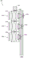
Fig. 15 shows a side view of an example of an eyepiece having a waveguide stack with overlapping incoupling optical elements.
Fig. 16 shows a side view of an example of a waveguide stack with color filters to mitigate ghosting or crosstalk between waveguides.
Fig. 17 shows an example of a top view of the eyepiece of fig. 15 and 16.
Fig. 18 shows another example of a top view of the eyepiece of fig. 15 and 16.
Figure 19A illustrates a side view of an example of an eyepiece having a waveguide stack with overlapping and laterally offset incoupling optical elements.
FIG. 19B shows a side view of an example of the eyepiece of FIG. 19A with color filters to mitigate ghosting or crosstalk between waveguides.
Fig. 20A shows an example of a top view of the eyepiece of fig. 19A and 19B.
Fig. 20B shows another example of a top view of the eyepiece of fig. 19A and 19B.
Fig. 21 shows a side view of an example of rebound (rebound) in a waveguide.
Fig. 22A to 22C show examples of top views of eyepieces having coupled-in optical elements configured to reduce bounce.
Fig. 23A-23C illustrate additional examples of top views of eyepieces having coupled-in optical elements configured to reduce bounce.
Fig. 24A shows an example of the angular emission distribution of light emitted by individual light emitters of a light emitting microdisplay and light captured by projection optics.
Fig. 24B shows an example of a contracted angular emission profile (profile) using a light collimator array.
FIG. 25A shows an example of a side view of a tapered array of reflective traps for directing light to projection optics.
Figure 25B shows an example of a side view of an asymmetric conical reflector well.
Fig. 26A to 26C show examples of optical path differences of light emitters at different positions with respect to a center line of an overlying lens.
FIG. 27 shows an example of a side view of individual light emitters of a light emitting microdisplay with an overlying nanolens array.
Fig. 28 is a perspective view of an example of the light emitting microdisplay of fig. 27.
Fig. 29 shows an example of a wearable display system with the full-color light emitting microdisplay of fig. 28.
Fig. 30A shows an example of a wearable display system with an emitting microdisplay and an associated array of light collimators.
Fig. 30B shows an example of a light projection system having a plurality of light emitting micro-displays, each having an associated array of light collimators.
Fig. 30C shows an example of a wearable display system with multiple light emitting microdisplays, each with an associated array of light collimators.
Fig. 31A and 31B illustrate examples of waveguide assemblies having a variable focus element for changing the wavefront divergence of light directed to a viewer.
FIG. 32A shows an example of an emitting microdisplay having an array of light emitters separated by gaps.
FIG. 32B shows an example of how the light emitting microdisplay of FIG. 32A can be configured to emulate a higher fill factor microdisplay via time multiplexing and repositioning of an array or associated optics.
Fig. 32C shows an example of a foveated image formed by a light emitting microdisplay such as that of fig. 32A.
FIG. 32D shows an example of a light emitting microdisplay, such as that of FIG. 32A, configured to form a foveated image with three or more resolution levels within an image.
FIG. 33 shows another example of a foveated image provided by a light emitting microdisplay, such as that of FIG. 32A.
FIG. 34 illustrates various example movement paths of an emitting microdisplay assembly for moving display pixel positions.
Fig. 35A and 35B show how the displacement of the light emitters and projection optics changes the position of the display pixels.
Fig. 36A shows an example of a wearable display system with a light projection system having an actuator coupled to projection optics.
Fig. 36B shows an example of a wearable display system with a light projection system having multiple actuators respectively coupled to different microdisplays.
Fig. 37A shows an example of a wearable display system with a light projection system having an eyepiece that includes a single waveguide.
Fig. 37B shows an example of a wearable display system with a light projection system in which a single light emitter array outputs different component colors of light through actuators coupled to projection optics.
Fig. 37C shows an example of a wearable display system similar to that of fig. 37B, except that the actuator is attached to the microdisplay instead of the projection optics.
Fig. 38A shows an example of a wearable display system with a light projection system that directs different component colors of light to an eyepiece without using an optical combiner to combine the different colors of light, and an actuator coupled to the projection optics.
Fig. 38B shows another example of a wearable display system with a light projection system that directs different component colors of light to an eyepiece without using an optical combiner to combine the different colors of light, and an actuator coupled to the projection optics.
Fig. 38C shows an example of a wearable display system similar to that of fig. 38A, except that the actuator is attached to a separate microdisplay instead of projection optics.
Fig. 38D shows an example of a wearable display system similar to that of fig. 38B, except that the actuators are attached to an integral microdisplay structure instead of projection optics.
FIG. 39 shows a flow diagram of an example process for outputting a sub-frame of a rendered frame of virtual content.
Detailed Description
An Augmented Reality (AR) or Virtual Reality (VR) system may display virtual content to a user or viewer. The content may be displayed, for example, on a head mounted display that is part of the glasses that projects image information to the user's eyes. Furthermore, when the system is an AR system, the display may also transmit light from the ambient environment to the eyes of the user to allow viewing of the ambient environment. As used herein, it should be understood that a "head mounted" or "head wearable" display is a display that may be mounted on the head of a user or viewer.
To improve the usability of an AR or VR system (also referred to simply as a "display system"), it is advantageous to reduce the size, weight, and/or power consumption of the display system. As an example, if the size and general prominence (general importance) of a display system is reduced, a user is more likely to use the display system. As another example, if the weight on the user's head is reduced, the user is more likely to use the display system. Also, reducing power consumption may allow for the use of smaller batteries, reducing the amount of heat generated by the display system, and so forth. Various embodiments described herein facilitate these benefits, including a reduction in the size of display system components.
As described herein, light (also referred to herein as image light) that forms virtual content may be generated by one or more display technologies. For example, the light may be generated by a light projection system included in the display system. The light may then be routed via optics to be output as virtual content to a user of the display system. The virtual content may be represented as image pixels included in rendered frames that are presented to the user in succession. To obtain high quality (e.g., realistic) virtual content, the display system may render frames of the virtual content at a sufficient resolution (e.g., greater than a threshold resolution) and then output them. Thus, the image pixels may be close enough to achieve sufficient resolution.
However, it should be appreciated that design constraints associated with display systems may limit the ability to achieve such proximity of image pixels, thereby limiting resolution. For example, in order to miniaturize the display system, it may be desirable for the display system to have a reduced display size (e.g., projector size). Example displays may include liquid crystal on silicon (LCoS) displays. To output image light forming virtual content, an LCoS display may be required to use a separate illumination module comprising one or more light emitters. In this example, the LCoS panel may apply a spatially varying modulation to the generated light to form virtual content. However, to reduce the size associated with LCoS panels while maintaining high resolution, it may be desirable to reduce the pixel pitch associated with the LCoS panels. As described herein, pixel pitch may represent a physical distance between similar locations of similar display elements forming an image pixel on a display. Due to physical limitations involving small pixel pitches, coupled with the need for separate illumination modules, LCoS displays may be larger than desired in certain applications.
Some embodiments disclosed herein advantageously include light emitting microdisplays, such as miniature LED displays. In some embodiments, the microdisplay is a miniature OLED display. Display systems utilizing light emitting microdisplays may avoid increased illumination module volume. Furthermore, light emitting microdisplays can facilitate the presentation of images with significantly advantageous small pixel pitches. As described, an example display system may utilize one or more light emitting microdisplays to achieve reduced size, weight, power consumption, and other benefits.
Light emitting microdisplays have several advantages for wearable display systems. For example, the power consumption of a light emitting microdisplay typically varies with image content, so dim or sparse content requires less power to display. Since AR environments are typically sparse, the average power consumption of light emitting microdisplays may be lower than that of other display technologies that use spatial light modulators to modulate light from a light source, since users typically want to be able to see their surroundings. In contrast, other display technologies may use a large amount of power even for dim, sparse, or "fully off" virtual content. As another example, an emitting microdisplay may provide an exceptionally high frame rate (which may allow the use of partial resolution arrays) and may provide a low level of apparent motion artifacts (e.g., motion blur). As another example, a light emitting microdisplay may not require the type of polarizing optics required for LCoS displays. Thus, the light emitting microdisplay can avoid optical losses present in the polarizing optics.
While light emitter arrays such as micro-LEDs provide significant size, weight, and/or power savings, current light emitters may not provide pixel pitches small enough to achieve high resolution virtual content in a small display system form factor. By way of non-limiting example, some micro-LED based microdisplays may allow for a pixel pitch of about 2 to about 3 microns. Even at such pixel pitches, in order to provide the required number of pixels, miniature LED displays may still be undesirably large, not usable in wearable display systems, particularly because the goal of these systems is to have a form factor and size similar to eyeglasses.
As described in more detail, a light projection system including an emitting microdisplay may achieve an effectively small pixel pitch via rapid physical adjustment or shifting of components of the light projection system. For example, a light emitting microdisplay may be physically repositioned or physically displaced along one or more axes. As another example, an optical element (e.g., projection optics) may be physically adjusted in position or physically displaced along one or more axes.
As described herein, the dimensions associated with a light emitter, such as a micro LED, may be referred to as emitter dimensions. Emitter size may refer to the size of the light emitter along a particular axis (e.g., a lateral axis). Emitter size may also refer to the size of the light emitter along two axes (e.g., a lateral axis and a longitudinal axis). Similarly, pixel pitch may refer to the distance between similar points on immediately adjacent light emitters along a particular axis (e.g., a horizontal axis), with different axes having their own pixel pitch. For example, in some embodiments, the placement of the light emitters is closer along a first axis than along a second axis (e.g., orthogonal axes). An example of a light emitter array is described in more detail herein and shown in fig. 32A.
It should be appreciated that the light emitter size may be smaller than the gap separating immediately adjacent light emitters. For example, forming an emitting microdisplay with an optical emitter above a threshold density can be challenging due to physical and electrical limitations. Example constraints may include current crowding, substrate sagging, and the like. Thus, there may be a large amount of gaps or spaces between adjacent light emitters. The gap between two light emitters is referred to herein as the inter-emitter region. Thus, the inter-emitter region (an example of which is shown in fig. 32A) may depict the region (e.g., the largest region) of an emitting microdisplay that includes a single light emitter. Thus, the size of the inter-emitter region may limit the extent to which the light emitting microdisplay can achieve some high density or high resolution.
Advantageously, the ability to operate light emitters such as micro-LEDs at high speed may allow for time multiplexed presentation of images using the same one or more light emitting micro-displays; for example, the geometric position of the light emitters relative to the projection optics may be moved to allow the same light emitter to present different pixels of the image at different times. In some embodiments, the rendered frames of virtual content may be presented in a series of subframes in rapid succession via a time-multiplexing scheme. In this example, each subframe may be associated with a particular physical location of the light emitter relative to the projection optics. Thus, it should be understood that the geometric position may be changed by changing the position of the light emitter and the projection optics relative to each other (e.g., by changing the physical position of the light emitter while the projection optics remain stationary; by changing the physical position of the projection optics while the light emitter remains stationary; or by changing the physical position of the light emitter and the projection optics at the same time). As described in more detail below, the geometric positions may be adjusted (e.g., via one or more actuators) such that the light emitters tile (tile) the respective inter-emitter regions. Accordingly, the light emitting microdisplay can achieve output of virtual content with advantageously high resolution.
Accordingly, the light projection system may be configured to project individual full resolution frames of virtual content by projecting one or more partial resolution sub-frames. For example, one or more partial resolution sub-frames may be projected. The subframes may be projected in rapid succession and may be offset from each other (e.g., by less than a full pixel pitch along one or more axes on which the subframes translate). For example, an emitting microdisplay included in a projector may be physically displaced along one or more axes. As described above, a light emitting microdisplay may include a light emitter, such as a micro LED, with a pixel pitch. Thus, the pixel pitch may inform the light emitting microdisplay of the resolution at which the virtual content frame is output. To effectively reduce the gap between the functional pixel pitch and the light emitters, and thus improve the resolution of a same size display, the position of the light emitters may be adjusted, for example by being smaller than the pixel pitch. For example, a display may include light emitters separated by a pixel pitch of 2.5 microns, and each light emitter may have an emitter size of 0.833 microns. In some embodiments, the position of the light emitters may be adjusted multiple times based on the number of times the light emitters translate to different (e.g., non-overlapping) positions within the inter-emitter region. In this example, the inter-emitter region may be 6.25 square microns, and the example light emitter may adjust the position three times along a first axis and adjust the position three times along a second orthogonal axis. Thus, the example light emitter may effectively occupy 9 positions within the inter-emitter region. For one or more of the 9 locations, a particular sub-frame of the same rendered frame of virtual content may be presented. Accordingly, the sub-frames of the continuous presentation may be perceived as high resolution frames of the virtual content. In practice, the light emitters may form an image with an apparent pixel density higher than the physical density of the light emitters.
In some embodiments, the user's visual system may merge sub-frames together so that the user perceives a full resolution frame. For example, the pixels of the sub-frames may be interleaved to form a full resolution frame. Preferably, the sub-frames may be sequentially displayed at a frame rate higher than a human visual system flicker fusion (flicker fusion) threshold. For example, the flicker fusion threshold may be 60Hz, which is considered to be fast enough that most users do not perceive that the sub-frames are displayed at different times. In some embodiments, the different sub-frames are sequentially displayed at a rate equal to or above a flicker fusion threshold (e.g., equal to or above 60 Hz).
Thus, the light emitting microdisplay may be configured to have fewer light emitters than the number of image pixels contained in each full-resolution rendered frame of virtual content. For example, a full resolution image may comprise 2000 x 2000 pixels, while a light emitting microdisplay may be an array of only 1000 x 1000 elements. The use of lower resolution light emitting microdisplays is particularly beneficial for wearable systems such as the display systems described herein. For example, lower resolution displays may be smaller, lighter in weight, and/or consume less power than high resolution displays.
While moving or adjusting the position of a light emitting micro-display (e.g., comprising a micro LED array) has been described above, it should be understood that the position of the projection optics may alternatively or additionally be adjusted. For example, and as will be described in more detail below with respect to fig. 35A-35B, the projection optics may route (route) light generated via the light emitting microdisplay to a user of the display system. As an example, the projection optics may route light to incoupling optics (e.g., incoupling gratings) of an eyepiece configured to receive light encoded with image information (image light) and direct the light to a user. Thus, instead of physically translating the light emitting microdisplay, the projection optics may be translated along one or more axes. In motion, the projection optics may change the geometric position of each array along one or more axes before outputting light coupled in via the incoupling grating. As described herein, a light projection system may include one or more light emitting micro-displays, projection optics, and the like. Thus, the light output of the light projection system may be adjusted by physical translation of the system components (e.g., by changing the position of pixels rendered by the light projection system).
It should be understood that some portions of the rendered frame of virtual content may be visually more apparent to the user than other portions. For example, a user may have a higher visual acuity for a portion of virtual content that falls on the user's fovea (fovea) (referred to herein as the "foveal portion"). To determine the location of these foveal portions, the display system may determine the point of regard at which the user is looking. Portions of virtual content that fall within a threshold angular distance of the point of regard may be identified as falling on the user's fovea. As will be described, the display system may be configured to increase the resolution associated with the foveal portion. The remaining portion has a smaller or no increase in resolution.
As an example, the light emitting microdisplay may be configured to update pixels included in the foveal portion at a higher rate than pixels included in other portions. As described above, the geometric positions of the light emitters may be translated or adjusted to tile the inter-emitter regions of the array. Alternatively, the light emitters used to output light forming pixels comprising the foveal region may be updated for a relatively high proportion of different geometric positions (e.g. for each different geometric position), while the light emitters used to form pixels away from the foveal region may be updated for a lower proportion of different geometric positions (e.g. these light emitters may be "off" or may only present the same information as the previous position). The update frequency of the light emitters for outputting light forming pixels included in other areas may be low. For example, for a given full resolution rendered frame of virtual content, the phototransmitters may be updated twice or only once. For example, the phototransmitters corresponding to the fovea may be updated for each of four different geometric positions within the inter-emitter region, while the phototransmitters corresponding to the peripheral portion of the image may be updated only for every other geometric position.
Thus, a rendered frame formed of rapidly displayed or projected sub-frames may have an effective resolution that varies across the rendered frame. With foveated imaging, the effective resolution of the light emitting microdisplay is caused to increase in foveated regions (e.g., regions of interest, regions focused by a user, user-specified regions, designer-specified regions, etc.) while decreasing in other regions (e.g., regions outside of regions of interest). Providing a foveated image by configuring a light emitting microdisplay may further help conserve (convert) resources, for example by eliminating and/or reducing processing and power loads associated with displaying or projecting regions of less interest (e.g., regions that are less likely to be of interest to a user).
Example display System with light emitting microdisplays
Advantageously, as described herein, display systems utilizing light emitting microdisplays described herein may allow for weight savings and reduced form factor, and may also provide high frame rate and low motion blur. Preferably, the microdisplay is a light emitting microdisplay that provides advantages of high brightness and high pixel density. In some embodiments, the light emitting microdisplay is a miniature LED display. In some other embodiments, the light emitting microdisplay is a miniature OLED display. In some embodiments, an emissive microdisplay includes an array of light emitters having a pitch of, for example, less than 10 μm, less than 8 μm, less than 6 μm, less than 5 μm, or less than 2 μm, including 1 to 5 μm, and an emitter size of 2 μm or less, 1.7 μm or less, or 1.3 μm or less. In some embodiments, the emitter size is within a range having an upper limit of the above size and a lower limit of 1 μm. In some embodiments, the ratio of emitter size to spacing is 1:1 to 1:5, 1:2 to 1:4, or 1:2 to 1:3, which facilitates individual control of the emitters and efficient utilization of light emitted by the eyepiece, as discussed further herein.
In some embodiments, multiple light emitting microdisplays may be utilized to form an image suitable for a head mounted display system. The light containing image information for forming these images may be referred to as image light. It should be understood that the image light may vary in, for example, wavelength, intensity, polarization, and the like. The light emitting microdisplay outputs image light to an eyepiece, which then passes the light to the user's eye.
In some embodiments, multiple light emitting microdisplays may be used and positioned on different faces of an optical combiner (e.g., an X-cube (X-cube) prism or a dichroic X-cube). An X-cube prism receives light from different microdisplays on different faces of the cube and outputs light from the same face of the cube. The output light may be directed to projection optics configured to converge or focus the image light onto an eyepiece.
In some embodiments, the plurality of light emitting microdisplays includes monochrome microdisplays configured to output light of a single component color. The various component colors are combined to form a full color image. In some other embodiments, one or more of the light emitting microdisplays may have subpixels configured to emit light of two or more, but not all, of the component colors used by the display system. For example, a single light emitting microdisplay may have subpixels that emit blue and green light, while separate light emitting microdisplays located on different faces of the X-cube may have pixels configured to emit red light. In some embodiments, the plurality of microdisplays are each full-color displays comprising pixels formed, for example, from a plurality of sub-pixels configured to emit light of different component colors. Advantageously, by combining the light of multiple full-color microdisplays, the display brightness and dynamic range may be increased.
It should be understood that the light emitting microdisplay may include an array of light emitters. The light emitter may emit light having a Lambertian angular emission distribution. Disadvantageously, this angular emission distribution "wastes" light because only a small portion of the emitted light is ultimately incident on the eyepiece. In some embodiments, the angular emission distribution of light emitted by the light emitter may be narrowed using a light collimator. As used herein, a light collimator is an optical structure that shrinks the angular emission distribution of incident light; that is, the light collimator receives light from the associated light emitter having a relatively wide initial angular emission distribution and outputs light having an angular emission distribution that is narrower than the wide initial angular emission distribution. In some embodiments, the light rays exiting the light collimator are more parallel than the light rays received by the light collimator before being transmitted through and exiting the collimator. Examples of light collimators include microlenses, nanolens, reflective traps, super surfaces, and liquid crystal gratings. In some embodiments, the light collimator may be configured to redirect light to ultimately converge on different laterally offset light coupling optical elements. In some embodiments, each light emitter has a dedicated light collimator. The light collimator is preferably positioned directly adjacent or in contact with the light emitters to capture a substantial portion of the light emitted by the associated light emitter.
In some embodiments, a single light emitting microdisplay may be utilized to direct light to an eyepiece. For example, the single light emitting microdisplay may be a full color display that includes light emitters that emit different component colors of light. In some embodiments, the light emitters may form groups located in a common area, wherein each group comprises light emitters emitting light of each component color. In such embodiments, each group of light emitters may share a common microlens. Advantageously, different colors of light from different light emitters take different paths through the microlens, which may be manifested as different component colors of light incident on different incoupling optical elements of the eyepiece, as discussed herein.
In some embodiments, a full-color microdisplay may include a repeating group of light emitters having the same component color. For example, a microdisplay may include multiple rows of light emitters, with each individual row of light emitters configured to emit the same color of light. Thus, different rows may emit different component colors of light. Further, the microdisplay may have an associated array of light collimators configured to direct light to a desired location on the eyepiece, e.g., to an associated incoupling optical element. Advantageously, while the individual light emitters of such a full-color microdisplay may not be positioned to form a high-quality full-color image, as seen directly on the microdisplay, the lens array appropriately directs light from the light emitters to an eyepiece that combines the monochromatic images formed by the different color light emitters to form a high-quality full-color image.
In some embodiments, an eyepiece receiving image light from a microdisplay may include a waveguide assembly. The waveguide region of the waveguide assembly upon which the image light is incident may include incoupling optics that incouple the incident image light such that the light propagates through the waveguide by Total Internal Reflection (TIR). In some embodiments, a waveguide assembly may include a stack of waveguides, each waveguide having an associated incoupling optical element. Different incoupling optical elements may be configured to incouple different colors of light, such that different waveguides may be configured to propagate different colors of light therein. The waveguide may comprise outcoupling optical elements that outcouple light propagating therein such that the outcoupled light propagates towards the eye of the user. In some other embodiments, the waveguide assembly may include a single waveguide having associated incoupling optical elements configured to incouple different component colors of light.
In some embodiments, the incoupling optics are laterally displaced as seen from the projection optics. Different incoupling optical elements may be configured to couple in different colors of light. Preferably, the image light of different colors reaches the eyepiece through different paths and thus impinges on different corresponding incoupling optical elements.
In some other embodiments, other types of eyepieces or optics may be utilized to deliver the image light to the user's eyes. For example, as discussed herein, the eyepiece may include one or more waveguides in which image light propagates by TIR. As another example, the eyepiece may include a Birdbath combiner that includes a semi-transparent mirror that directs image light to a viewer and allows viewing of the surrounding environment.
In some embodiments, the eyepiece may be configured to selectively output light having different amounts of wavefront divergence to provide virtual content at a plurality of virtual depth planes (also referred to herein simply as "depth planes") that are perceived as having different distances from the user. For example, the eyepiece may include a plurality of waveguides, each waveguide including an out-coupling optical element having a different optical power (optical power) to output light having a different amount of wavefront divergence. In some other embodiments, a variable focus element may be disposed between the eyepiece and the user's eye. The variable focus element may be configured to dynamically change the optical power to provide a desired wavefront divergence for a particular virtual content. In some embodiments, the display system may further include a plurality of lenses that provide or provide additional optical power in place of or in addition to the waveguide optical structure used to provide the optical power.
In addition to the compact form factor and high frame rate discussed above, light emitting microdisplays according to some embodiments may provide one or more of the following advantages. For example, microdisplays can provide extremely small pixel pitches and extremely high pixel densities. Microdisplays can also provide high brightness and efficiency. For example, a light emitter of a light emitting microdisplay may only consume power to emit light when the light emitter is required to provide content with brightness. This is in contrast to other display technologies, in which a light source may illuminate the entire panel of pixels, regardless of whether some of the pixels are dark. Further, it should be appreciated that the human visual system integrates the light received over a period of time, and that the light emitter of a light emitting microdisplay, such as a miniature LED, advantageously has a high duty cycle (e.g., including short activation periods where the light emitter in the microdisplay rises from "off" to a fully "on" state, and correspondingly short periods of time from "on" to "off" state, allowing the light emitter to emit light at an on level for a large portion of each period). Thus, the power used to produce an image with a given perceived brightness may be less than conventional display techniques with lower duty cycles. In some embodiments, the duty cycle may be 70% or more, 80% or more, or 90% or more. In some embodiments, the duty cycle may be about 99%. Further, as described herein, the microdisplay can facilitate extremely high frame rates, which can provide advantages including reducing mismatches between user head position and display content.
Reference will now be made to the drawings, wherein like reference numerals refer to like parts throughout. Unless otherwise indicated, the drawings are schematic and are not necessarily drawn to scale.
Fig. 2 illustrates a conventional display system for simulating a three-dimensional image for a user. It will be appreciated that the eyes of the user are spaced apart and that when viewing a real object in space, each eye has a slightly different view of the object and that a view of the object may be formed at a different location on the retina of each eye. This may be referred to as binocular parallax and may be used by the human visual system to provide depth perception. Conventional display systems simulate binocular disparity by presenting two different images 190, 200 with slightly different views of the same virtual object, one for each eye 210, 220, which correspond to the view of the virtual object seen by each eye as a real object at the desired depth. These images provide binocular cues that the user's visual system can interpret to obtain depth perception.
With continued reference to fig. 2, the images 190, 200 are spaced apart from the eyes 210, 220 by a distance 230 in the z-axis. The z-axis is parallel to the optical axis of a viewer whose eyes gaze at an optically infinite distance object located directly in front of the viewer. The images 190, 200 are flat and held at a fixed distance from the eyes 210, 220. Based on the slightly different views of the virtual object in the images presented to the eyes 210, 220, respectively, the eyes may naturally rotate such that the image of the object falls on a corresponding point on the retina of each eye to maintain single binocular vision. This rotation may cause the line of sight of each eye 210, 220 to converge on a point in space where the virtual object is perceived to be present. Thus, providing a three-dimensional image typically involves providing binocular cues that can manipulate the vergence of the user's eyes 210, 220 and be interpreted by the human visual system to provide depth perception.
However, it is challenging to produce a realistic and comfortable depth perception. It should be appreciated that light from objects spaced at different distances from the eye have wavefronts with different amounts of divergence. Fig. 3A to 3C show the relationship between the distance and the light ray divergence. The distances between the object and the eye 210 are represented in the order of decreasing distance R1, R2, and R3. As shown in fig. 3A to 3C, as the distance to the object decreases, the light rays become more divergent. Conversely, as the distance increases, the light rays become more collimated. In other words, the light field produced by a point (object or portion of an object) can be considered to have a spherical wavefront curvature that is a function of how far the point is from the user's eye. The curvature increases as the distance between the object and the eye 210 decreases. Although only a single eye 210 is shown in fig. 3A-3C and other figures herein for clarity of illustration, the discussion regarding eye 210 may apply to both eyes 210 and 220 of the viewer.
With continued reference to fig. 3A-3C, light from an object at which the eyes of the viewer are gazing may have varying degrees of wavefront divergence. Due to the different amounts of wavefront divergence, the light may be focused differently by the lens of the eye, which in turn may require the lens to assume different shapes to form a focused image on the retina of the eye. In the case where a focused image is not formed on the retina, the resulting retinal blur acts as an accommodation cue that causes a change in the shape of the eye's lens until a focused image is formed on the retina. For example, accommodation cues may trigger relaxation or contraction of the ciliary muscle around the lens of the eye, thus, adjusting the force applied to the zonules holding the lens, changing the shape of the lens of the eye until the retinal blur of the gazing object is eliminated or minimized, thereby forming a focused image of the gazed object at the retina (e.g., the fovea) of the eye. The process by which the lens of the eye changes shape may be referred to as accommodation, and the shape of the lens of the eye required to form a focused image of the object of fixation on the retina (e.g., the fovea) of the eye is referred to as the state of accommodation.
Referring now to FIG. 4A, a representation of the accommodation-vergence response of the human visual system is shown. The eye moves to fixate on the object causing the eye to receive light from the object, wherein the light forms an image on each retina of the eye. The presence of retinal blur in the image formed on the retina may provide accommodative cues, and the relative position of the image on the retina may provide vergence cues. Accommodation cues cause accommodation to occur, causing the lenses of the eyes to each assume a particular state of accommodation that forms a focused image of an object at the retina (e.g., the fovea) of the eye. On the other hand, the vergence cord causes vergence motion (eye rotation) to occur such that the image formed on each retina of each eye is at the corresponding retinal point that preserves single binocular vision. At these locations, the eye may be considered to have been in a particular state of vergence. With continued reference to fig. 4A, accommodation may be understood as the process by which the eye achieves a particular state of accommodation, and vergence may be understood as the process by which the eye achieves a particular state of vergence. As shown in fig. 4A, if the user gazes at another object, the accommodation and vergence states of the eyes may change. For example, if the user gazes at a new object at a different depth on the z-axis, the adjustment state may change.
Without being limited by theory, it is believed that a viewer of an object may perceive the object as "three-dimensional" due to a combination of vergence and accommodation. As described above, vergence motion of the two eyes relative to each other (e.g., the eyes rotate such that the pupils move toward or away from each other to cause the line of sight of the eyes to fixate on the object by convergence) is closely related to the accommodation of the eye's lens. Under normal circumstances, changing the shape of the lens of the eye to change the focus from one object to another at a different distance will automatically result in a change in vergence to the same distance, according to a relationship known as "accommodation-vergence reflection". Also, under normal conditions, a change in vergence will trigger a change in the lens shape matching.
Referring now to fig. 4B, an example of different accommodative and vergence states of the eye is shown. The pair of eyes 222a fixates on an object at optical infinity, and the pair of eyes 222b fixates on an object 221 at less than optical infinity. It is noted that the vergence state of each pair of eyes is different, and the pair of eyes 222a is looking straight ahead, and the pair of eyes 222 is focused on the subject 221. The accommodation state of the eyes forming each pair of eyes 222a and 222b may also be different, as shown by the different shapes of lenses 210a, 220 a.
However, many users of conventional "3D" display systems find such conventional systems uncomfortable or unable to perceive depth at all due to mismatches between the adjustment and vergence states in these displays. As described above, many stereoscopic or "3D" display systems display a scene by providing slightly different images to each eye. Such systems are uncomfortable for many viewers, as they only provide different presentations of the scene and cause changes in eye vergence, but the accommodation state of these eyes does not change accordingly. Instead, the image is shown by the display at a fixed distance relative to the eye, such that the eye views all image information in a single state of accommodation. This arrangement addresses "accommodation-vergence reflection" by causing a vergence state change in the event that no matching change in accommodation occurs. This mismatch is believed to cause discomfort to the viewer. A display system that provides a better match between accommodation and vergence may result in a more realistic and comfortable three-dimensional image simulation.
Without being limited by theory, it is believed that the human eye can typically interpret a limited number of depth planes to provide depth perception. Thus, a highly reliable perceptual depth simulation may be achieved by providing the eye with different image presentations corresponding to each of these limited number of depth planes. In some embodiments, the different presentations may provide both vergence cues and matching accommodation cues, thereby providing physiologically correct accommodation-vergence matching.
With continued reference to fig. 4B, two depth planes 240 are shown, which correspond to different spatial distances relative to the eyes 210, 220. For a given depth plane 240, vergence cues may be provided by displaying images with suitably different viewing angles for each eye 210, 220. Furthermore, for a given depth plane 240, the light forming the image provided to each eye 210, 220 may have a wavefront divergence corresponding to the light field produced by the point at the distance of that depth plane 240.
In the illustrated embodiment, the distance along the z-axis of the depth plane 240 containing the point 221 is 1 meter. As used herein, distance or depth along the z-axis may be measured with a zero point located at the exit pupil of the user's eye. Thus, a depth plane 240 located at a depth of 1 meter corresponds to a position on the optical axis of these eyes that is 1 meter from the exit pupil of the user's eye, where the eye is looking at optical infinity. As an approximation, the depth or distance along the z-axis may be measured from a display in front of the user's eye (e.g., from the surface of the waveguide), plus the value of the distance between the device and the user's eye exit pupil. This value may be referred to as eye relief and corresponds to the distance between the user's eye exit pupil (exit pupil) and the display worn by the user in front of the eye. In practice, the value of eye relief may be a standardized value that is generally used for all viewers. For example, it may be assumed that the eye relief is 20mm and a depth plane with a depth of 1 meter may be at a distance of 980mm in front of the display.
Referring now to fig. 4C and 4D, examples of matched accommodation-vergence distances and mismatched accommodation-vergence distances are shown, respectively. As shown in fig. 4C, the display system may provide an image of the virtual object to each eye 210, 220. These images may cause the eyes 210, 220 to assume a state of vergence in which the eyes converge at point 15 on the depth plane 240. Further, the image may be formed from light having a wavefront curvature corresponding to the real object at the depth plane 240. As a result, the eyes 210, 220 assume an accommodation state in which the image is focused on the retinas of these eyes. Thus, the user may perceive that the virtual object is perceived to be located at point 15 on the depth plane 240.
It should be appreciated that each of the accommodative and vergence states of the eyes 210, 220 is associated with a particular distance on the z-axis. For example, objects at a particular distance from the eyes 210, 220 cause the eyes to assume a particular state of accommodation based on the distance of the objects. The distance associated with a particular adjustment state may be referred to as an adjustment distance Ad. Similarly, there is a particular vergence distance V associated with a particular vergence statedOr positions relative to each other. In the case where the accommodation distance and the vergence distance match, the relationship between accommodation and vergence can be considered physiologically correct. This is considered to be the most comfortable scene for the viewer.
However, in three dimensionsIn a display, the adjustment distance and the vergence distance may not always match. For example, as shown in FIG. 4D, the image displayed to the eye 210, 220 may be displayed by wavefront divergence corresponding to the depth plane 240, and the eye 210, 220 may assume a particular state of accommodation in which the points 15a, 15b on the depth plane are in focus. However, the images displayed to the eyes 210, 220 may provide a vergence cue that causes the eyes 210, 220 to converge at a point 15 that is not located on the depth plane 240. Thus, in some embodiments, the accommodation distance corresponds to a distance from the exit pupil of the eye 210, 220 to the depth plane 240, while the vergence distance corresponds to a greater distance from the exit pupil of the eye 210, 220 to the point 15. The adjustment distance is different from the vergence distance. Thus, there is a accommodation-vergence mismatch. This mismatch is considered undesirable and may cause discomfort to the user. It should be understood that mismatch corresponds to distance (e.g., V)d-Ad) And may be characterized using diopters.
In some embodiments, it should be understood that a reference point outside the exit pupil of the eye 210, 220 may be used to determine the distance and thus the accommodation-vergence mismatch, as long as the same reference point is used for both the accommodation distance and the vergence distance. For example, the distance from the cornea to the depth plane, from the retina to the depth plane, from the eyepiece (e.g., waveguide of a display device) to the depth plane, and so forth, can be measured.
Without being limited by theory, it is believed that the user can still perceive a physiologically correct accommodative-vergence mismatch of up to about 0.25 diopters, up to about 0.33 diopters, and up to about 0.5 diopters, where the mismatch itself does not cause significant discomfort. In some embodiments, a display system disclosed herein (e.g., display system 250 in fig. 6) presents an image to a viewer with a accommodative-vergence mismatch of about 0.5 diopters or less. In some other embodiments, the accommodative-vergence dissipation prescription for the image provided by the display system is about 0.33 diopters or less. In further embodiments, the accommodative-vergence dissipation prescription for the image provided by the display system is about 0.25 diopters or less (including about 0.1 diopters or less).
FIG. 5 illustrates some aspects of a method for simulating a three-dimensional image by modifying wavefront divergence. The display system includes a waveguide 270, the waveguide 270 configured to receive light 770 encoded with image information and output the light to the eye 210 of the user. Waveguide 270 may output light 650 having a defined amount of wavefront divergence corresponding to that of the optical field produced by the point on the desired depth plane 240. In some embodiments, the same amount of wavefront divergence is provided for all objects presented on the depth plane. In addition, it will be explained that image information from a similar waveguide can be provided to the other eye of the user.
In some embodiments, a single waveguide may be configured to output light having a set amount of wavefront divergence corresponding to a single or limited number of depth planes, and/or a waveguide may be configured to output light of a limited wavelength range. Thus, in some embodiments, multiple waveguides or waveguide stacks may be utilized to provide different amounts of wavefront divergence and/or output different wavelength ranges of light for different depth planes. As used herein, it should be understood that the depth plane may be flat or may follow the contour of a curved surface.
Fig. 6 shows an example of a waveguide stack for outputting image information to a user. The display system 250 includes a stack of waveguides or stacked waveguide assemblies 260 that may be used to provide three-dimensional perception to the eye/brain using a plurality of waveguides 270, 280, 290, 300, 310. It should be understood that in some embodiments, the display system 250 may be considered a light field display. Further, the waveguide assembly 260 may also be referred to as an eyepiece.
In some embodiments, display system 250 may be configured to provide a substantially continuous vergence cue and a plurality of discrete accommodation cues. The vergence cues may be provided by displaying different images to each eye of the user, and the accommodative cues may be provided by outputting light forming the images with a selectable amount of discrete wavefront divergence. In other words, the display system 250 may be configured to output light having a variable level of wavefront divergence. In some embodiments, each discrete wavefront divergence level corresponds to a particular depth plane and may be provided by a particular one of the waveguides 270, 280, 290, 300, 310.
With continued reference to fig. 6, the waveguide assembly 260 may also include a plurality of features 320, 330, 340, 350 between the waveguides. In some embodiments, the features 320, 330, 340, 350 may be one or more lenses. The waveguides 270, 280, 290, 300, 310 and/or the plurality of lenses 320, 330, 340, 350 may be configured to transmit image information to the eye at different levels of wavefront curvature or ray divergence. Each waveguide level may be associated with a particular depth plane and may be configured to output image information corresponding to that depth plane. The image injection devices 360, 370, 380, 390, 400 may be used as light sources for the waveguides and may be used to inject image information into the waveguides 270, 280, 290, 300, 310, each of which may be configured to distribute incident light across each respective waveguide for output toward the eye 210, as described herein. The light exits the output surfaces 410, 420, 430, 440, 450 of the image injection devices 360, 370, 380, 390, 400 and is injected into the corresponding input surfaces 460, 470, 480, 490, 500 of the waveguides 270, 280, 290, 300, 310. In some embodiments, each of the input surfaces 460, 470, 480, 490, 500 may be an edge of the corresponding waveguide, or may be a portion of a major surface of the corresponding waveguide (i.e., one of the waveguide surfaces that directly faces the world 510 or the observer's eye 210). In some embodiments, a single beam (e.g., a collimated beam) may be injected into each waveguide to output the entire field of a cloned collimated beam directed toward the eye 210 at a particular angle (and amount of divergence) corresponding to the depth plane associated with the particular waveguide. In some embodiments, a single one of the image injection devices 360, 370, 380, 390, 400 may be associated with multiple (e.g., three) waveguides 270, 280, 290, 300, 310 and inject light into the multiple (e.g., three) waveguides 270, 280, 290, 300, 310.
In some embodiments, the image injection devices 360, 370, 380, 390, 400 are discrete displays that each produce image information for injection into a corresponding waveguide 270, 280, 290, 300, 310, respectively. In some other embodiments, the image injection devices 360, 370, 380, 390, 400 are outputs of a single multiplexed display that can convey image information to each of the image injection devices 360, 370, 380, 390, 400, e.g., via one or more optical conduits (such as fiber optic cables). It will be understood that the image information provided by the image injection devices 360, 370, 380, 390, 400 may include light of different wavelengths or colors (e.g., different component colors, as discussed herein).
In some embodiments, the light injected into the waveguides 270, 280, 290, 300, 310 is provided by a light projection system 520, the light projection system 520 including a light module 530, which may include a light emitter such as a Light Emitting Diode (LED). Light from light module 530 can be directed and modified by light modulator 540 (e.g., a spatial light modulator) via beam splitter 550. The light modulator 540 may be configured to vary the perceived intensity of light injected into the waveguides 270, 280, 290, 300, 310 to encode the light with image information. Examples of spatial light modulators include Liquid Crystal Displays (LCDs), which include Liquid Crystal On Silicon (LCOS) displays. In some other embodiments, the spatial light modulator may be a MEMS device, such as a Digital Light Processing (DLP) device. It should be understood that the image injection devices 360, 370, 380, 390, 400 are schematically shown and, in some embodiments, may represent different optical paths and locations in a common projection system configured to output light to an associated one of the waveguides 270, 280, 290, 300, 310. In some embodiments, the waveguides of the waveguide assembly 260 may function as ideal lenses while delivering light injected into the waveguides to the user's eyes. In this concept, the object may be a spatial light modulator 540 and the image may be an image on a depth plane.
In some embodiments, the display system 250 may be a scanning fiber optic display, including one or more scanning fibers configured to project light in various patterns (e.g., raster scan, helical scan, Lissajous (Lissajous) pattern, etc.) into one or more waveguides 270, 280, 290, 300, 310 and ultimately to the eye 310 of the viewer. In some embodiments, the illustrated image injection devices 360, 370, 380, 390, 400 may schematically represent a single scanning fiber or a bundle of scanning fibers configured to inject light into one or more waveguides 270, 280, 290, 300, 310. In some other embodiments, the illustrated image injection devices 360, 370, 380, 390, 400 may schematically represent a plurality of scanning fibers or a plurality of bundles of scanning fibers, each of which is configured to inject light into an associated one of the waveguides 270, 280, 290, 300, 310. It will be understood that one or more optical fibers may be configured to transmit light from the optical module 540 to one or more waveguides 270, 280, 290, 300, 310. It will be appreciated that one or more intermediate optical structures may be provided between the scanning optical fiber or optical fiber and one or more waveguides 270, 280, 290, 300, 310, for example to redirect light exiting the scanning optical fiber to one or more waveguides 270, 280, 290, 300, 310.
The controller 560 controls the operation of one or more of the stacked waveguide assemblies 260, including the operation of the image injection apparatus 360, 370, 380, 390, 400, the light source 530, and the light modulator 540. In some embodiments, the controller 560 is part of the local data processing module 140. The controller 560 includes programming (e.g., instructions in a non-transitory medium) to regulate the timing and provision of image information to the waveguides 270, 280, 290, 300, 310 according to, for example, any of the various aspects disclosed herein. In some embodiments, the controller may be a single integrated device, or a distributed system connected by wired or wireless communication channels. In some embodiments, controller 560 may be part of processing module 140 or 150 (fig. 9E).
With continued reference to fig. 6, the waveguides 270, 280, 290, 300, 310 may be configured to propagate light within each respective waveguide by Total Internal Reflection (TIR). The waveguides 270, 280, 290, 300, 310 may each be planar or have another shape (e.g., curved) with major top and bottom surfaces and edges extending between those major top and bottom surfaces. In the illustrated configuration, the waveguides 270, 280, 290, 300, 310 may each include an out-coupling optical element 570, 580, 590, 600, 610 configured to extract light out of the waveguides by redirecting light propagating within each respective waveguide to output image information to the eye 210. The extracted light may also be referred to as outcoupled light, and the outcoupled optical element light may also be referred to as light extraction optical element. The extracted light beam may be output by the waveguide at a location where light propagating in the waveguide strikes the light extraction optical element. The outcoupling optical elements 570, 580, 590, 600, 610 may, for example, be gratings comprising diffractive optical features, as discussed further herein. Although illustrated as being disposed at the bottom major surface of the waveguides 270, 280, 290, 300, 310 for ease of description and clarity of the drawings, in some embodiments the out-coupling optical elements 570, 580, 590, 600, 610 may be disposed at the top and/or bottom major surfaces and/or may be disposed directly in the volume of the waveguides 270, 280, 290, 300, 310, as discussed further herein. In some embodiments, the out-coupling optical elements 570, 580, 590, 600, 610 may be formed in a layer of material attached to a transparent substrate to form the waveguides 270, 280, 290, 300, 310. In some other embodiments, the waveguides 270, 280, 290, 300, 310 may be a single piece of material, and the out-coupling optical elements 570, 580, 590, 600, 610 may be formed on a surface and/or in an interior portion of the piece of material.
With continued reference to fig. 6, as discussed herein, each waveguide 270, 280, 290, 300, 310 is configured to output light to form an image corresponding to a particular depth plane. For example, the waveguide 270 closest to the eye may be configured to deliver collimated light (which is injected into such a waveguide 270) to the eye 210. The collimated light may represent an optically infinite focal plane. A next upward waveguide (waveguide up)280 may be configured to send out collimated light that passes through a first lens 350 (e.g., a negative lens) before it can reach the eye 210; such a first lens 350 may be configured to produce a slight concave wavefront curvature such that the eye/brain interprets light from this next upward waveguide 280 as coming from a first focal plane closer inward from optical infinity toward the eye 210. Similarly, the third upward waveguide 290 has its output light pass through the first lens 350 and the second lens 340 before reaching the eye 210; the combined optical power of the first lens 350 and the second lens 340 can be configured to produce another increase in wavefront curvature such that the eye/brain interprets light from the third waveguide 290 as light from the second focal plane that is closer to the person from optical infinity inward than light from the next waveguide 280.
The other waveguide layers 300, 310 and lenses 330, 320 are similarly configured, with the highest waveguide 310 in the stack sending its output through all lenses between it and the eye, for representing the total optical power to the person's nearest focal plane. To compensate for the stack of lenses 320, 330, 340, 350 when viewing/interpreting light from the world 510 on the other side of the stacked waveguide assembly 260, a compensating lens layer 620 may be disposed on top of the stack to compensate for the total optical power of the underlying lens stack 320, 330, 340, 350. Such a configuration provides as many focal planes as there are waveguide/lens pairs available. Both the outcoupling optical elements of the waveguides and the focusing aspects of the lenses may be static (i.e. non-dynamic or electro-active). In some alternative embodiments, one or both may be dynamic using the electroactive feature.
In some embodiments, two or more of the waveguides 270, 280, 290, 300, 310 may have the same associated depth plane. For example, multiple waveguides 270, 280, 290, 300, 310 may be configured to output a set of images to the same depth plane, or multiple subsets of waveguides 270, 280, 290, 300, 310 may be configured to output a set of images to the same multiple depth planes, with one set for each depth plane. This may provide the advantage of forming stitched images to provide an extended field of view at those depth planes.
With continued reference to fig. 6, the out-coupling optical elements 570, 580, 590, 600, 610 may be configured to redirect light out of their respective waveguides and output the light with an appropriate amount of divergence or collimation for the particular depth plane associated with the waveguide. Thus, waveguides having different associated depth planes may have different configurations of out-coupling optical elements 570, 580, 590, 600, 610 that output light having different amounts of divergence depending on the associated depth plane. In some embodiments, the light extraction optics 570, 580, 590, 600, 610 may be volume or surface features, which may be configured to output light at a particular angle. For example, the light extraction optical elements 570, 580, 590, 600, 610 may be volume holograms, surface holograms, and/or diffraction gratings. In some embodiments, the features 320, 330, 340, 350 may not be lenses; instead, it may simply be a spacer (e.g., a cladding and/or a structure for forming an air gap).
In some embodiments, the outcoupling optical elements 570, 580, 590, 600, 610 are diffractive features that form a diffraction pattern, or "diffractive optical elements" (also referred to herein as "DOEs"). Preferably, the DOE has a sufficiently low diffraction efficiency such that only a portion of the beam is deflected away towards the eye 210 with each intersection (interaction) of the DOE, while the remaining portion continues to move through the waveguide via TIR. The light carrying the image information is thus split into a number of relevant exit beams leaving the waveguide at a number of locations, and the result is a fairly uniform pattern of exit emissions towards the eye 210 for this particular collimated beam bouncing around within the waveguide.
In some embodiments, one or more DOEs may be switchable between an "on" state in which it actively diffracts and an "off" state in which it DOEs not significantly diffract. For example, the switchable DOE may comprise a polymer dispersed liquid crystal layer, wherein the droplets comprise a diffraction pattern in a host medium, and the refractive index of the droplets may be switched to substantially match the refractive index of the host material (in which case the pattern DOEs not significantly diffract incident light) or the droplets may be switched to a refractive index that DOEs not match the refractive index of the host medium (in which case the pattern actively diffracts incident light).
In some embodiments, a camera component 630 (e.g., a digital camera, including visible and infrared light cameras) may be provided to capture images of the eye 210 and/or tissue surrounding the eye 210, for example, to detect user input and/or to monitor a physiological state of the user. As used herein, a camera may be any image capture device. In some embodiments, camera component 630 may include an image capture device and a light source that projects light (e.g., infrared light) toward the eye, which may then be reflected by the eye and detected by the image capture device. In some embodiments, camera assembly 630 may be attached to frame or support structure 80 (fig. 9E) and may be in electrical communication with processing module 140 and/or 150, which processing module 140 and/or 150 may process image information from camera assembly 630. In some embodiments, one camera assembly 630 may be utilized for each eye to monitor each eye separately.
In some embodiments, the camera component 630 may observe the motion of the user, such as the eye motion of the user. As an example, the camera component 630 may capture an image of the eye 210 to determine a size, position, and/or orientation of a pupil of the eye 210 (or some other structure of the eye 210). If desired, the camera component 630 may obtain images (processed by processing circuitry of the type described herein) for determining the direction in which the user is gazing (e.g., eye pose or gaze direction). In some embodiments, camera component 630 may include multiple cameras, at least one of which may be used for each eye to independently determine an eye pose or gaze direction for each eye, respectively. In some embodiments, the camera component 630, in conjunction with processing circuitry such as the controller 560 or the local data processing module 140, may determine an eye pose or gaze direction based on glints (e.g., reflections) of reflected light (e.g., infrared light) from light sources included in the camera component 630.
Referring now to fig. 7, an example of an exit beam output by a waveguide is shown. One waveguide is illustrated, but it will be understood that other waveguides in the waveguide assembly 260 (fig. 6) may operate similarly where the waveguide assembly 260 includes multiple waveguides. Light 640 is injected into waveguide 270 at input surface 460 of waveguide 270 and propagates within waveguide 270 by TIR. At the point where light 640 is incident on DOE 570, a portion of the light exits the waveguide as exit beam 650. The exit beam 650 is illustrated as being substantially parallel, but as discussed herein, it may also be redirected to propagate at an angle to the eye 210 (e.g., forming a diverging exit beam), depending on the depth plane associated with the waveguide 270. It will be understood that substantially parallel exiting beams may be indicative of a waveguide having outcoupled optical elements that outcouple light to form an image that appears to be set at a depth plane that is a large distance (e.g., optical infinity) from the eye 210. Other waveguides or other sets of outcoupling optical elements may output a more divergent exit beam pattern that would require the eye 210 to adjust to a closer distance to focus it on the retina and would be interpreted by the brain as light from a distance closer to the eye 210 than optical infinity.
In some embodiments, a full-color image may be formed at each depth plane by overlapping images of each of the component colors (e.g., three or more component colors). Fig. 8 illustrates an example of a stacked waveguide assembly in which each depth plane includes an image formed using a plurality of different component colors. The illustrated embodiment shows depth planes 240 a-240 f, but more or less depths are also contemplated. Each depth plane may have three or more component color images associated therewith, including: a first image of a first color G; a second image of a second color R; and a third image of a third color B. The different depth planes are indicated in the figures by different numbers for diopters (dpt) following the letters G, R and B. By way of example only, the numbers following each of these letters indicate diopter (1/m), or the reverse distance of the depth plane from the viewer, and each box in the drawing represents a separate component color image. In some embodiments, the exact positioning of the depth planes for the different color components may be varied in order to account for differences in eye focus for different wavelengths of light. For example, different component color images for a given depth plane may be placed on the depth plane corresponding to different distances from the user. Such an arrangement may increase visual acuity and user comfort and/or may reduce chromatic aberrations.
In some embodiments, each component color of light may be output by a single dedicated waveguide, and thus, each depth plane may have multiple waveguides associated therewith. In such embodiments, each box in the diagram including the letter G, R or B may be understood to represent a separate waveguide, and three waveguides may be provided per depth plane, wherein three color component images are provided per depth plane. Although the waveguides associated with each depth plane are shown adjacent to each other in this figure, it will be understood that in a physical device, the waveguides may all be arranged in a stack with one waveguide per layer. In some other embodiments, multiple component colors may be output by the same waveguide, such that, for example, only a single waveguide may be provided per depth plane.
With continued reference to fig. 8, in some embodiments, G is green, R is red, and B is blue. In some other embodiments, other colors associated with other wavelengths of light (including magenta and cyan) may additionally be used or may replace one or more of red, green, or blue.
It will be understood that reference throughout this disclosure to a given color of light will be understood to encompass light of one or more wavelengths within a range of wavelengths of light perceived by an observer as having that given color. For example, red light may include light at one or more wavelengths in the range of about 620-780 nm, green light may include light at one or more wavelengths in the range of about 492-577 nm, and blue light may include light at one or more wavelengths in the range of about 435-493 nm.
In some embodiments, light source 530 (fig. 6) may be configured to emit light at one or more wavelengths outside the visual perception range of the viewer, e.g., infrared and/or ultraviolet wavelengths. In addition, the incoupling, outcoupling and other light redirecting structures of the waveguide of display 250 may be configured to direct and emit this light out of the display towards the eye 210 of the user, e.g. for imaging and/or user stimulation applications.
Referring now to fig. 9A, in some embodiments, light incident on the waveguide may need to be redirected to couple the light into the waveguide. The incoupling optical elements may be used to redirect and incouple light into their corresponding waveguides. FIG. 9A illustrates a cross-sectional side view of an example of a plurality or set of stacked waveguides 660 each comprising an incoupling optical element. The waveguides may each be configured to output light of one or more different wavelengths or one or more different wavelength ranges. It will be understood that the stack 660 may correspond to the stack 260 (fig. 6), and the illustrated waveguides of the stack 660 may correspond to a portion of the plurality of waveguides 270, 280, 290, 300, 310, except that light from one or more of the image injection devices 360, 370, 380, 390, 400 is injected into the waveguides from a location that requires light redirection for incoupling.
The illustrated stacked waveguide set 660 includes waveguides 670, 680, and 690. Each waveguide includes an associated incoupling optical element (which may also be referred to as a light input region on the waveguide), where, for example, incoupling optical element 700 is disposed on a major surface (e.g., an upper major surface) of waveguide 670, incoupling optical element 710 is disposed on a major surface (e.g., an upper major surface) of waveguide 680, and incoupling optical element 720 is disposed on a major surface (e.g., an upper major surface) of waveguide 690. In some embodiments, one or more of the incoupling optical elements 700, 710, 720 may be disposed on the bottom major surface of the respective waveguide 670, 680, 690 (particularly where the one or more incoupling optical elements are reflective deflecting optical elements). As illustrated, incoupling optical elements 700, 710, 720 may be disposed on the upper major surface of their respective waveguides 670, 680, 690 (or on top of the next lower waveguide), particularly where those incoupling optical elements are transmissive deflection optical elements. In some embodiments, the incoupling optical elements 700, 710, 720 may be disposed in the body of the respective waveguides 670, 680, 690. In some embodiments, the incoupling optical elements 700, 710, 720 are wavelength selective such that they selectively redirect one or more wavelengths of light while transmitting other wavelengths of light, as discussed herein. Although illustrated on one edge or corner of its respective waveguide 670, 680, 690, it will be understood that in some embodiments, incoupling optical elements 700, 710, 720 may be disposed in other regions of its respective waveguide 670, 680, 690.
As shown, the incoupling optical elements 700, 710, 720 may be laterally offset from each other, as seen in the front view shown, in the direction of light propagation to these incoupling optical elements. In some embodiments, each incoupling optical element may be offset such that it receives light without the light passing through another incoupling optical element. For example, each incoupling optical element 700, 710, 720 may be configured to receive light from a different image injection device 360, 370, 380, 390, and 400 as shown in fig. 6, and may be separated (e.g., laterally spaced) from the other incoupling optical elements 700, 710, 720 such that it does not substantially receive light from the other of the incoupling optical elements 700, 710, 720.
Each waveguide also includes associated light distribution elements, for example, light distribution element 730 disposed on a major surface (e.g., top major surface) of waveguide 670, light distribution element 740 disposed on a major surface (e.g., top major surface) of waveguide 680, and light distribution element 750 disposed on a major surface (e.g., top major surface) of waveguide 690. In some other embodiments, light distribution elements 730, 740, 750 may be arranged on the bottom major surface of associated waveguides 670, 680, 690, respectively. In some other embodiments, light distribution elements 730, 740, 750 may be disposed on the top and bottom major surfaces of associated waveguides 670, 680, 690, respectively; or light distribution elements 730, 740, 750 may be arranged on different ones of the top and bottom main surfaces in different associated waveguides 670, 680, 690, respectively.
The waveguides 670, 680, 690 may be separated and separated by layers of, for example, gas, liquid, and/or solid materials. For example, as illustrated, layer 760a may separate waveguides 670 and 680; and layer 760b may separate waveguides 680 and 690. In some embodiments, layers 760a and 760b are formed of a low index material (i.e., a material having a lower index of refraction than the material forming the immediately adjacent one of waveguides 670, 680, 690). Preferably, the refractive index of the material forming layers 760a, 760b is 0.05 or more, or 0.10 or less, less than the refractive index of the material forming waveguides 670, 680, 690. Advantageously, the lower index layers 760a, 760b may act as cladding layers that facilitate Total Internal Reflection (TIR) of light passing through the waveguides 670, 680, 690 (e.g., TIR between the top and bottom major surfaces of each waveguide). In some embodiments, the layers 760a, 760b are formed of air. Although not illustrated, it will be understood that the top and bottom of the illustrated waveguide set 660 may include immediately adjacent cladding layers.
Preferably, the waveguides 670, 680, 690 are formed of similar or identical materials and the layers 760a, 760b are formed of similar or identical materials for ease of fabrication and other considerations. In some embodiments, the material forming waveguides 670, 680, 690 may be different between one or more waveguides, and/or the material forming layers 760a, 760b may be different, while still maintaining the various refractive index relationships noted above.
With continued reference to FIG. 9A, light rays 770, 780, 790 are incident on waveguide set 660. It will be appreciated that light rays 770, 780, 790 may be injected into waveguides 670, 680, 690 by one or more image injection devices 360, 370, 380, 390, 400 (fig. 6).
In some embodiments, the light 770, 780, 790 has different properties, e.g., different wavelengths or different wavelength ranges, which may correspond to different colors. The incoupling optical elements 700, 710, 720 each deflect incident light such that the light propagates through a respective one of the waveguides 670, 680, 690 by TIR. In some embodiments, the incoupling optical elements 700, 710, 720 each selectively deflect one or more particular wavelengths of light while transmitting other wavelengths to the underlying waveguide and associated incoupling optical elements.
For example, the incoupling optical element 700 may be configured to deflect light 770, the light 770 having a first wavelength or wavelength range, while transmitting light 780 and 790, respectively, having different second and third wavelengths or wavelength ranges. The transmitted light 780 is incident on the incoupling optical element 710 and is deflected by the incoupling optical element 710, which incoupling optical element 710 is configured to deflect light of a second wavelength or wavelength range. The light 790 is deflected by incoupling optics 720, the incoupling optics 720 being configured to selectively deflect light of a third wavelength or wavelength range.
With continued reference to fig. 9A, deflected rays 770, 780, 790 are deflected such that they propagate through corresponding waveguides 670, 680, 690; that is, the incoupling optical elements 700, 710, 720 of each waveguide deflect light into the corresponding waveguide 670, 680, 690 to couple light into the corresponding waveguide. Light rays 770, 780, 790 are deflected at angles that cause the light to propagate through the respective waveguides 670, 680, 690 by TIR. Light rays 770, 780, 790 propagate through the respective waveguide 670, 680, 690 by TIR until being incident on the respective light distribution element 730, 740, 750 of the waveguide.
Referring now to fig. 9B, a perspective view of an example of the multiple stacked waveguides of fig. 9A is illustrated. As described above, the incoupled light 770, 780, 790 is deflected by the incoupled optical elements 700, 710, 720, respectively, and then propagates within the waveguides 670, 680, 690, respectively, by TIR. Light rays 770, 780, 790 are then incident on light distribution elements 730, 740, 750, respectively. The light distribution elements 730, 740, 750 deflect the light rays 770, 780, 790 such that they propagate towards the out-coupling optical elements 800, 810, 820, respectively.
In some embodiments, the light distribution elements 730, 740, 750 are Orthogonal Pupil Expanders (OPE). In some embodiments, the OPE deflects or distributes the light to the outcoupling optical elements 800, 810, 820, and in some embodiments, the beam or spot size may also be increased as it propagates to the outcoupling optical elements. In some embodiments, the light distribution elements 730, 740, 750 may be omitted and the incoupling optical elements 700, 710, 720 may be configured to deflect light directly into the outcoupling optical elements 800, 810, 820. For example, referring to fig. 9A, the light distribution elements 730, 740, 750 may be replaced by outcoupling optical elements 800, 810, 820, respectively. In some embodiments, the outcoupling optical elements 800, 810, 820 are Exit Pupils (EP) or Exit Pupil Expanders (EPE) that direct light into the eye 210 (fig. 7) of an observer. It will be understood that the OPE may be configured to increase the size of an eye box (eye box) in at least one axis, and the EPE may increase the eye box in an axis that spans (e.g., is orthogonal to) the axis of the OPE. For example, each OPE may be configured to redirect a portion of light incident on the OPE to an EPE of the same waveguide by allowing the remainder of the light to continue propagating down the waveguide. Upon re-incidence on the OPE, another portion of the remaining light is redirected to the EPE, and the remainder of that portion continues to propagate further down the waveguide, and so on. Similarly, upon incidence of an EPE, a portion of the incident light is directed out of the waveguide toward the user, and the remainder of that portion continues to propagate through the waveguide until it again impinges the EP, at which time another portion of the incident light is directed out of the waveguide, and so on. Thus, a single beam of coupled-in light can be "replicated" each time a portion of the light is redirected by the OPE or EPE, thereby forming a field that clones the light beam, as shown in fig. 6. In some embodiments, the OPE and/or EPE may be configured to modify the size of the light beam.
Thus, referring to fig. 9A and 9B, in some embodiments, waveguide set 660 includes waveguides 670, 680, 690; coupling optical elements 700, 710, 720; light distribution elements (e.g. OPE)730, 740, 750; and an outcoupling optical element (e.g., EPE)800, 810, 820 for each component color. Waveguides 670, 680, 690 may be stacked with a void/cladding between each. The incoupling optical elements 700, 710, 720 redirect or deflect incident light (where different incoupling optical elements receive light of different wavelengths) into their respective waveguides. The light then propagates at an angle that will result in TIR within the respective waveguides 670, 680, 690. In the example shown, light 770 (e.g., blue light) is deflected by the first incoupling optical element 700 in the manner previously described, and then continues to bounce down the waveguide, interacting with light distribution element (e.g., OPE)730 and then outcoupling optical element (e.g., EP) 800. Light rays 780 and 790 (e.g., green and red, respectively) will pass through waveguide 670, where light ray 780 is incident on incoupling optical element 710 and is deflected by incoupling optical element 710. Light ray 780 then bounces down waveguide 680 via TIR, continues to its light distribution element (e.g., OPE)740 and then is coupled out of optical element (e.g., EP) 810. Finally, light ray 790 (e.g., red light) passes through waveguide 690 to impinge on light incoupling optics 720 of waveguide 690. The light incoupling optical element 720 deflects the light rays 790 such that the light rays propagate by TIR to a light distribution element (e.g. OPE)750 and then to an outcoupling optical element (e.g. EP) 820. The out-coupling optical element 820 then finally out-couples the light 790 to a viewer who also receives the out-coupled light from the other waveguides 670, 680.
Fig. 9C illustrates a top plan view of an example of the multiple stacked waveguides of fig. 9A and 9B. It should be understood that this top view is also referred to as a front view, as seen along the direction of light propagation towards the incoupling optical elements 800, 810, 820; that is, the top view is a view of the waveguide where the image light is incident perpendicular to the page. As illustrated, the waveguides 670, 680, 690 together with each waveguide's associated light distribution element 730, 740, 750 and associated outcoupling optical element 800, 810, 820 may be vertically aligned. However, as discussed herein, the incoupling optical elements 700, 710, 720 are not vertically aligned; in contrast, the incoupling optical elements are preferably non-overlapping (e.g., laterally spaced, as viewed in a top-down view). As discussed further herein, this non-overlapping spatial arrangement facilitates injecting light from different sources into different waveguides on a one-to-one basis, thereby allowing a particular light source to be uniquely coupled to a particular waveguide. In some embodiments, arrangements comprising non-overlapping spatially separated incoupling optical elements may be referred to as offset pupil systems, and the incoupling optical elements within these arrangements may correspond to sub-pupils.
It should be understood that the spatially overlapping regions may have a lateral overlap of 70% or more, 80% or more, or 90% or more of their area, as seen in top view. On the other hand, as seen in top view, there are lateral shift regions that are less than 30% overlapping, less than 20% overlapping, or less than 10% overlapping. In some embodiments, the laterally displaced regions do not overlap.
Fig. 9D illustrates a top plan view of another example of a plurality of stacked waveguides. As shown, the waveguides 670, 680, 690 may be vertically aligned. However, in contrast to the configuration of fig. 9C, the individual light distribution elements 730, 740, 750 and the associated outcoupling optical elements 800, 810, 820 are omitted. Instead, the light distribution elements and the outcoupling optical elements effectively overlap and occupy the same area as seen in top view. In some embodiments, light distribution elements (e.g., OPE) may be disposed on one major surface of waveguides 670, 680, 690, while outcoupling optical elements (e.g., EPE) may be disposed on the other major surface of these waveguides. Thus, each waveguide 670, 680, 690 may have superimposed light distribution elements and light out-coupling optical elements, collectively referred to as combined OPE/EPE1281, 1282, 1283, respectively. Further details regarding this combination OPE/EPE can be found in us application No. 16/221,359 filed on 12/14/2018, the entire disclosure of which is incorporated herein by reference. The incoupling optical elements 700, 710, 720 couple light in and direct it to the combined OPE/EPE1281, 1282, 1283, respectively. In some embodiments, as shown, the incoupling optical elements 700, 710, 720 may be laterally displaced (e.g., they are laterally spaced apart as seen in the top view shown) to have a displaced pupil spatial arrangement. As with the configuration of fig. 9C, this laterally shifted spatial arrangement facilitates the one-to-one injection of different wavelengths of light (e.g., from different light sources) into different waveguides.
Fig. 9E illustrates an example of a wearable display system 60 in which the various waveguides and related systems disclosed herein may be integrated. In some embodiments, the display system 60 is the system 250 of fig. 6, where fig. 6 schematically illustrates certain components of the system 60 in more detail. For example, the waveguide assembly 260 of fig. 6 may be part of the display 70.
With continued reference to fig. 9E, the display system 60 includes a display 70, as well as various mechanical and electronic modules and systems that support the functionality of the display 70. The display 70 may be connected to a frame 80 that is wearable by a display system user or viewer 90 and is configured to position the display 70 in front of the eyes of the user 90. In some embodiments, the display 70 may be considered glasses. The display 70 may include one or more waveguides, such as waveguide 270, configured to relay the coupled-in image light and output the image light to the eye of the user 90. In some embodiments, a speaker 100 is coupled to the frame 80 and configured to be positioned near the ear canal of the user 90 (in some embodiments, another speaker (not shown) may be selectively positioned near the other ear canal of the user to provide stereo/shapeable sound control). The display system 60 may also include one or more microphones 110 or other devices that detect sound. In some embodiments, the microphone is configured to allow a user to provide input or commands to the system 60 (e.g., selection of voice menu commands, natural language questions, etc.) and/or may allow audio communication with others (e.g., with other users of similar display systems). The microphone may also be configured as a peripheral sensor to collect audio data (e.g., sounds from the user and/or the environment). In some embodiments, the display system 60 may also include one or more outward facing environmental sensors 112 configured to detect objects, stimuli, people, animals, locations, or other aspects of the user's surrounding world. For example, the environmental sensor 112 may include one or more cameras, which may be positioned, for example, outward to capture images similar to at least a portion of the general field of view of the user 90. In some embodiments, the display system may also include peripheral sensors 120a, which may be separate from the frame 80 and attached to the body of the user 90 (e.g., on the head, torso, limbs, etc. of the user 90). In some embodiments, the peripheral sensor 120a may be configured to acquire data characterizing a physiological state of the user 90. For example, the sensor 120a may be an electrode.
With continued reference to fig. 9E, the display 70 is operatively connected to a local data processing module 140 by a communication link 130 (e.g., by a wired lead or wireless connection), and the local data processing module 140 may be mounted in various configurations, such as fixedly attached to the frame 80, fixedly attached to a helmet or hat worn by the user, embedded in headphones, or otherwise removably attached to the user 90 (e.g., in a backpack configuration, in a strapped configuration). Similarly, the sensor 120a may be operatively connected to the local processing and data module 140 via a communication link 120b (e.g., via a wired lead or wireless connection). The local processing and data module 140 may include a hardware processor, as well as digital memory, such as non-volatile memory (e.g., flash memory or a hard drive), both of which may be used to facilitate processing, caching, and data storage. Alternatively, the local processing and data module 140 may include one or more Central Processing Units (CPUs), Graphics Processing Units (GPUs), dedicated processing hardware, and the like. Such data may include a) data captured by sensors (which may be, for example, operatively connected to the frame 80 or otherwise attached to the user 90), such as image capture devices (e.g., cameras), microphones, inertial measurement units, accelerometers, compasses, GPS units, radios, gyroscopes, and/or other sensors disclosed herein; and/or b) data (including data relating to virtual content) obtained and/or processed using remote processing module 150 and/or remote data store 160, which may be communicated to display 70 after such processing or retrieval has been performed. The local processing and data module 140 may be operatively connected to the remote processing module 150 and the remote data store 160 by communication links 170, 180 (such as via wired or wireless communication links) such that these remote modules 150, 160 are operatively connected to each other and available as resources to the local processing and data module 140. In some embodiments, the local processing and data module 140 may include one or more of an image capture device, a microphone, an inertial measurement unit, an accelerometer, a compass, a GPS unit, a radio, and/or a gyroscope. In some other embodiments, one or more of these sensors may be attached to the frame 80, or may be a separate structure in communication with the local processing and data module 140 through a wired or wireless communication path.
With continued reference to fig. 9E, in some embodiments, the remote processing module 150 may include one or more processors configured to analyze and process data and/or image information, e.g., including one or more Central Processing Units (CPUs), Graphics Processing Units (GPUs), dedicated processing hardware, and so forth. In some embodiments, the remote data repository 160 may include a digital data storage facility, which may be available through the internet or other network configuration in a "cloud" resource configuration. In some embodiments, remote data store 160 may include one or more remote servers that provide information, such as information used to generate virtual content, to local processing and data module 140 and/or remote processing module 150. In some embodiments, all data is stored and all computations are performed in local processing and data modules, allowing for fully autonomous use from remote modules. Alternatively, an external system (e.g., a system of one or more processors, one or more computers) including a CPU, GPU, etc. may execute at least a portion of the processor (e.g., generate image information, process data), and provide information to and receive information from modules 140, 150, 160, e.g., via a wireless or wired connection.
Fig. 10 shows an example of a wearable display system with a light projection system 910, the light projection system 910 having a spatial light modulator 930 and a separate light source 940. Light source 940 may include one or more light emitters and illuminates a Spatial Light Modulator (SLM) 930. Lens structure 960 may be used to focus light from light source 940 onto SLM 930. A beam splitter (e.g., a Polarizing Beam Splitter (PBS))950 reflects light from a light source 940 to the spatial light modulator 930, and the spatial light modulator 930 reflects and modulates the light. The reflected modulated light, also referred to as image light, then propagates through beam splitter 950 to eyepiece 920. Another lens configuration, projection optics 970, may be used to converge or focus image light onto eyepiece 920. Eyepiece 920 may include one or more waveguides that deliver the modulated signal to eye 210.
As described herein, the individual light sources 940 and associated lens structures 960 may undesirably increase the weight and size of the wearable display system. This can reduce the comfort of the display system, particularly for users who wear the display system for extended periods of time.
Furthermore, the light source 940 in conjunction with the SLM 930 may consume power inefficiently. For example, light source 940 illuminates the entire SLM 930. SLM 930 then selectively reflects the light to eyepiece 920. Thus, not all of the light generated by the light source 940 is used to form an image; some of this light, e.g., light corresponding to dark areas of the image, is not reflected to eyepiece 920. Thus, light source 940 uses energy to generate light to illuminate the entire SLM 930, but only a small portion of the light is required to form some image.
Further, as described herein, in some cases, SLM 930 may modulate light using micro-mirrors to selectively reflect incident light, or use liquid crystal molecules that change the amount of light reflected from an underlying mirror. Thus, these devices require physical movement of optical elements (e.g., micromirrors or liquid crystal molecules, such as in LCoS or DLP panels, respectively) in order to modulate light from the light source 940. The physical movement required to modulate the light so as to encode the light with image information (e.g., corresponding to a pixel) occurs at a relatively slow speed compared to the ability to, for example, "turn on" or "turn off" an LED or OLED. Such relatively slow movements may limit the frame rate of the display system and may occur in the form of rendered images that are, for example, motion blurred, dispersed, and/or mismatched with the user's head pose or the pose changes.
Advantageously, the wearable display utilizing light emitting microdisplays disclosed herein can facilitate a wearable display system with relatively low weight and volume, high energy efficiency, and high frame rate, and with low motion blur and low motion blur delay. Low blur and low motion-to-photon delay (motion-to-photon delay) are further discussed in U.S. provisional application No. 62/786199, filed on 28.12.2018, the entire disclosure of which is incorporated herein by reference. Furthermore, compared to scanning fiber displays, light emitting microdisplays can avoid artifacts caused by the use of coherent light sources.
Referring now to fig. 11A, there is shown an example of a wearable display system having a light projection system 1010 with a plurality of light emitting micro-displays 1030a, 1030b, 1030 c. Light from microdisplays 1030a, 1030b, 1030c is combined by optical combiner 1050 and directed to eyepiece 1020, and eyepiece 1020 delivers the light to user's eye 210. Projection optics 1070 may be disposed between optical combiner 1050 and eyepiece 1020. In some embodiments, eyepiece 1020 may be a waveguide assembly that includes one or more waveguides. In some embodiments, the light projection system 1010 and the eyepiece 1020 can be supported by (e.g., attached to) the frame 80 (fig. 9E).
In some embodiments, the microdisplays 1030a, 1030b, 1030c can be monochrome microdisplays that each output light of a different component color to provide a monochrome image. As discussed herein, monochrome images are combined to form a full color image.
In some other embodiments, the microdisplays 1030a, 1030b, 1030c can each be a full-color display configured to output light of all component colors. For example, microdisplays 1030a, 1030b, 1030c include red, green, and blue light emitters, respectively. The microdisplays 1030a, 1030b, 1030c can be identical and can display identical images. However, utilizing multiple microdisplays may provide the advantage of increasing image brightness and dynamic range, particularly by combining light from multiple microdisplays to form a single image. In some embodiments, two or more (e.g., three) microdisplays may be used, with optical combiner 1050 configured to combine light from all of these microdisplays.
The microdisplay may include an array of light emitters. Examples of light emitters include Organic Light Emitting Diodes (OLEDs) and micro light emitting diodes (micro LEDs). It is understood that OLEDs utilize organic materials to emit light, while micro LEDs utilize inorganic materials to emit light. Advantageously, some micro-LEDs provide higher brightness and higher efficiency (in lux/W) than OLEDs. In some embodiments, the microdisplays are preferably light emitting micro LED displays.
With continued reference to fig. 11A, the micro-displays 1030a, 1030b, 1030c may be configured to emit image light 1032a, 1032b, 1032c, respectively. In the case where the microdisplays are monochrome microdisplays, the image light 1032a, 1032b, 1032c may each have a different component color. Optical combiner 1050 receives image light 1032a, 1032b, 1032c and effectively combines these light such that the light travels generally in the same direction, e.g., toward projection optics 1070. In some embodiments, optical combiner 1050 may be a dichroic X-cube prism having reflective interior surfaces that redirect image light 1032a, 1032b, 1032c to projection optics 1070. It should be appreciated that projection optics 1070 may be a lens structure that includes one or more lenses that converge or focus image light onto eyepiece 1020. The eyepiece 1020 then relays the image light 1032a, 1032b, 1032c to the eye 210.
In some embodiments, the eyepiece 1020 can include a plurality of stacked waveguides 1020a, 1020b, 1020c, each having a respective incoupling optical element 1022a, 1022b, 1022 c. In some embodiments, the number of waveguides is proportional to the number of component colors provided by the microdisplays 1030a, 1030b, 1030 c. For example, where there are three component colors, the number of waveguides in eyepiece 1020 may include one or more sets of waveguides, each set including three waveguides. In some embodiments, each group may output light having a wavefront divergence corresponding to a particular depth plane, as discussed herein. It should be understood that the waveguides 1020a, 1020b, 1020C and incoupling optical elements 1022a, 1022b, 1022C may correspond to the waveguides 670, 680, 690 and incoupling optical elements 700, 710, 720 of fig. 9A-9C, respectively. From the perspective of the projection optics 1070, the incoupling optics 1022a, 1022b, 1022c may be laterally displaced so that they do not overlap at least partially as seen in this view.
As shown, the various incoupling optical elements disclosed herein (e.g., incoupling optical elements 1022a, 1022b, 1022c) can be disposed on a major surface of an associated waveguide (e.g., waveguides 1020a, 1020b, 1020c, respectively). Further, as also shown, the major surface on which a given incoupling optical element is disposed may be the back surface of the waveguide. In such a configuration, the incoupling optical element may be a reflective light redirecting element that incouples light through an associated waveguide by reflecting light at an angle that supports TIR. In some other configurations, the incoupling optics may be disposed on the front surface of the waveguide (closer to the projection optics 1070 than the back surface). In such a configuration, the incoupling optical elements may be transmitted light redirecting elements that incouple light by changing the propagation direction of the light as it is transmitted through the incoupling optical elements. It should be understood that any of the incoupling optical elements disclosed herein may be reflective or transmissive incoupling optical elements.
With continued reference to fig. 11A, image light 1032a, 1032b, 1032c from different micro displays 1030a, 1030b, 1030c may reach the eyepiece 1020 by different paths to impinge on different incoupling optical elements 1022a, 1022b, 1022 c. Where the image light 1032a, 1032b, 1032C includes different component colors of light, the associated incoupling optical elements 1022a, 1022b, 1022C may be configured to selectively incouple different wavelengths of light, respectively, as discussed above with respect to, for example, the incoupling optical elements 700, 710, 720 of fig. 9A-9C.
With continued reference to fig. 11A, the optical combiner 1050 may be configured to redirect the image light 1032a, 1032b, 1032c emitted by the micro displays 1030a, 1030b, 1030c such that the image light propagates along different optical paths so as to impinge on an appropriate one of the incoupling optical elements 1022a, 1022b, 1022 c. Thus, optical combiner 1050 combines image light 1032a, 1032b, 1032c in the sense that the image light is output from a common face of optical combiner 1050, although the light may exit the optical combiner in slightly different directions. For example, the reflective inner surfaces 1052, 1054 of the X-cube prisms may be angled, respectively, to direct image light 1032a, 1032b, 1032c along different paths to the eyepiece 1020. As a result, the image light 1032a, 1032b, 1032c may be incident on different associated ones of the incoupling optical elements 1022a, 1022b, 1022 c. In some embodiments, the microdisplays 1030a, 1030b, 1030c can be appropriately angled relative to the reflective inner surfaces 1052, 1054 of the X-cube prisms to provide the desired optical paths to the incoupling optical elements 1022a, 1022b, 1022 c. For example, the face of one or more of the microdisplays 1030a, 1030b, 1030c can be tilted to match the face of the optical combiner 1050 so that image light emitted by the microdisplays is incident on the reflective inner surfaces 1052, 1054 at the appropriate angle to propagate toward the associated incoupling optical element 1022a, 1022b, or 1022 c. It should be understood that optical combiner 1050 may take the form of a variety of other polyhedrons in addition to a cube. For example, optical combiner 1050 may take the shape of a right angle prism where at least two faces are not square.
With continued reference to FIG. 11A, in some embodiments, monochrome microdisplay 1030b directly opposite output face 1051 can advantageously output green light. It will be appreciated that the reflective surfaces 1052, 1054 may have optical losses when reflecting light from the microdisplay. Furthermore, the human eye is most sensitive to green. Accordingly, monochromatic microdisplay 1030b opposite output face 1051 preferably outputs green light, so that the green light can pass directly through optical combiner 1050 without being output from optical combiner 1050 by reflection. However, it should be understood that in some other embodiments, the green monochromatic microdisplay may face other surfaces of optical combiner 1050.
As discussed herein, in some embodiments, user perception of full-color images may be achieved using time-division multiplexing. For example, different light emitting microdisplays 1030a, 1030b, 1030c may be activated at different times to produce different component color images. In such embodiments, the different component color images forming a single full-color image may be displayed sequentially fast enough that the human visual system cannot perceive the component color images to be displayed at different times; that is, all of the different component color images forming a single full-color image may be displayed for a sufficiently short duration so that the user perceives the component color images as being presented simultaneously, rather than at different times. For example, it should be understood that the human visual system may have a flicker fusion threshold. The flicker fusion threshold may be understood as the duration of time that the human visual system is unable to distinguish between images presented at different times. The images presented during this duration are fused or combined and, thus, may be perceived by the user as being presented simultaneously. Flicker images in which the time interval between images is outside the duration are not merged, and flicker of the images is noticeable. In some embodiments, the duration is 1/60 seconds or less, which corresponds to a frame rate of 60Hz or higher. Preferably, the image frames facing any single eye are provided to the user at a frame rate equal to or above the flicker fusion threshold duration for the user. For example, the frame rate for each of the left-eye or right-eye eyepieces may be 60Hz or higher, or 120Hz or higher; thus, in some embodiments, the frame rate provided by the light projection system 1010 may be 120Hz or higher, or 240Hz or higher.
It should be appreciated that time division multiplexing may advantageously reduce the computational load on a processor (e.g., a graphics processor) used to form the display image. In some other embodiments, all component color images forming a full color image may be displayed simultaneously by the microdisplays 1030a, 1030b, 1030c, e.g., with sufficient available computing resources.
As discussed herein, the microdisplays 1030a, 1030b, 1030c can each include an array of light emitters. Fig. 11B shows an example of an array 1042 of light emitters 1044. In the case where the associated microdisplays are monochrome microdisplays, the light emitters 1044 may all be configured to emit the same color light.
In the case where the associated microdisplay is a full-color microdisplay, the different light emitters 1044 can be configured to emit different colors of light. In such embodiments, the light emitters 1044 may be considered to be sub-pixels and may be arranged in groups, with each group having at least one light emitter configured to emit light of each component color. For example, where the component colors are red, green and blue, each group may have at least one red subpixel, at least one green subpixel and at least one blue subpixel.
It should be understood that although the light emitters 1044 are shown arranged in a grid pattern for ease of illustration, the light emitters 1044 may have other regularly repeating spatial arrangements. For example, the number of light emitters of different component colors may vary, the size of the light emitters may vary, the shape of the light emitters and/or the shape assumed by the group of light emitters may vary, and so forth.
With continued reference to fig. 11B, it should be appreciated that micro-emitter 1044 emits light. Furthermore, manufacturing constraints, such as photolithography or other patterning and processing constraints, and/or electrical constraints may limit the tightness of spacing of adjacent light emitters 1044. Thus, there may be a region 1045 surrounding the light emitters 1044 in which it is impractical to form other light emitters 1044. The region 1045 forms an inter-emitter region between the light emitters 1044. In some embodiments, the light emitters have a pitch of, for example, less than 10 μm, less than 8 μm, less than 6 μm, or less than 5 μm and greater than 1 μm (including 1 to 5 μm), and an emitter size of 2 μm or less, 1.7 μm or less, or 1.3 μm or less, in view of region 1045. In some embodiments, the emitter size is within a range having an upper limit of the above size and a lower limit of 1 μm. In some embodiments, the ratio of emitter size to pitch is 1:1 to 1:5, 1:2 to 1:4, or 1:2 to 1: 3.
It will be appreciated that given some light emitter device architectures and materials, current crowding can reduce the efficiency of the emitters, and pixel droop can lead to inadvertent activation of pixels (e.g., due to energy directed to one light emitter permeating into an adjacent light emitter). Thus, the relatively large region 1045 may beneficially reduce current crowding and pixel droop. In some embodiments, the ratio of emitter size to pitch is preferably 1:2 to 1:4, or 1:2 to 1: 3.
However, it should also be appreciated that large spacing between light emitters (e.g., small light emitter to pitch ratio) may undesirably result in visible gaps or dark regions between the light emitters. Even when the lateral translation discussed herein occurs, some gaps are still visible, depending on the original gap size, the translation distance, and the number of subframes used (and the resulting translation increment). In some embodiments, these dark regions may be effectively filled or partially filled with a lens structure such as a light collimator. For example, a light collimating lens may extend over and around the light emitters 1044 such that the light from the emitters 1044 completely fills the lens. For example, the width of the light collimating lens may be greater than the light emitters 1044, and in some embodiments, the width of the collimating lens may be about equal to the pitch. Thus, the size of emitter 1044 is effectively increased to extend across the lens region, filling some or all of region 1045. In some other embodiments, the width of the collimating lens may be approximately equal to the distance the projection system is translated for each sub-frame as discussed herein. Lens structures such as light collimators are discussed further herein (e.g., in fig. 30A and related discussion).
As discussed herein, the light emitter 1044 may be an OLED or a micro LED. It is to be understood that OLEDs may utilize layers of organic materials, for example, disposed between electrodes to emit light. Micro LEDs may utilize inorganic materials, such as group III-V materials, e.g., GaAs, GaN, and/or GaIn for light emission. Examples of GaN materials include InGaN, which may be used in some embodiments to form a blue or green light emitter. Examples of GaIn materials include AlGaInP, which may be used to form red light emitters in some embodiments. In some embodiments, the light emitter 1044 may emit light having an initial color that may be converted to other desired colors using phosphor materials or quantum dots. For example, the light emitter may emit blue light that excites phosphor materials or quantum dots, converting light at the blue light wavelengths to green or red light wavelengths.
Referring now to fig. 12, another example of a wearable display system with a light projection system having multiple light emitting micro-displays 1030a, 1030b, 1030c is shown. The display system shown is similar to that of FIG. 11A, except that optical combiner 1050 has a standard X-cube prism configuration and includes light redirecting structures 1080a and 1080c for changing the angle of incidence of light on the reflective surfaces 1052, 1054 of the X-cube prisms. It will be appreciated that a standard X-cube prism configuration will receive light perpendicular to the faces of the X-cube and redirect that light 45 ° out of the lateral faces of the X-cube at a normal angle. However, this results in image light 1032a, 1032b, 1032c being incident on the same incoupling optical element of eyepiece 1020. To provide different paths for image light 1032a, 1032b, 1032c such that the image light is incident on associated ones of the incoupling optical elements 1022a, 1022b, 1022c of the waveguide assembly, light redirecting structures 1080a, 1080c may be utilized.
In some embodiments, the light redirecting structures 1080a, 1080c may be lens structures. It should be appreciated that the lens structures may be configured to receive incident light and redirect the incident light at an angle such that the light is reflected from a respective one of the reflective surfaces 1052, 1054 and propagates along the optical path to a respective one of the incoupling optical elements 1022a, 1022 c. As examples, the light redirecting structures 1080a, 1080c may include microlenses, nanolens, reflective traps, metasurfaces (metal surfaces), and liquid crystal gratings. In some embodiments, the microlenses, nanolens, reflective traps, super surfaces, and liquid crystal gratings may be arranged in an array. For example, each light emitter of the microdisplays 1030a, 1030c can be matched to a microlens. In some embodiments, to redirect light in a particular direction, the microlens or reflective trap may be asymmetric and/or the light emitter may be disposed off-center with respect to the microlens. Further, in some embodiments, the light redirecting structures 1080a, 1080c may be collimators that narrow the angular emission distribution of the associated light emitters to increase the amount of light that is ultimately coupled into the eyepiece 1020. Further details regarding such light redirecting structures 1080a, 1080C are discussed below with respect to fig. 24A-27C.
Referring now to fig. 13A, in some embodiments, two or more of the incoupling optical elements 1022a, 1022b, 1022c can overlap (e.g., as seen in elevation along the direction of light propagation to the incoupling optical elements 1022a, 1022b, 1022 c). Fig. 13A shows an example of a side view of a wearable display system with a light projection system 1010 having multiple light emitting micro-displays 1032a, 1032b, 1032c and an eyepiece 1020 with overlapping light incoupling optical elements 1022a, 1022c and non-overlapping light incoupling optical elements 1022 b. As shown, the incoupling optical elements 1022a, 1022c overlap, while the incoupling optical element 1022b is laterally displaced. In other words, the incoupling optical elements 1022a, 1022c are directly aligned with the paths of the image light 1032a, 1032c, while the image light 1032b follows another path to the eyepiece 1020, shifting the region of the eyepiece 1020 into which it is incident laterally with respect to the region into which the image light 1032a, 1032c is incident.
As shown, the difference between the paths of image light 1032b and image light 1032a, 1032c may be established using light redirecting structures 1080a, 1080 c. In some embodiments, image light 1032b from light emitting microdisplay 1030b passes directly through optical combiner 1052. Image light 1032a from light emitting microdisplay 1032a is redirected by light redirecting structure 1080a so that it reflects from reflective surface 1054 and propagates out of optical combiner 1050 in the same direction as image light 1032 c. It should be appreciated that image light 1032c from light emitting micro-display 1032c is redirected by light redirecting structure 1080c to reflect from reflective surface 1052 at an angle such that image light 1032c propagates out of optical combiner 1050 in the same direction as image light 1032 b. Thus, the redirection of light by light redirecting structures 1080a, 1080c and the angle of reflective surfaces 1052, 1054 are configured to provide a common path for image light 1032a, 1032c to exit optical combiner 1050 that is different than the path of image light 1032 b. In some other embodiments, one or both of light redirecting structures 1080a, 1080c may be omitted, and reflective surfaces 1052, 1054 in optical combiner 1050 may be configured to reflect image light 1032a, 1032c in the appropriate respective directions such that the image light exits optical combiner 1050 and propagates in the same direction as the direction of image light 1032 b. Thus, after propagating through the projection optics 1070, image light 1032a, 1032c exits from one exit pupil, while image light 1032b exits from the other exit pupil. In this configuration, the light projection system 1010 may be referred to as a dual pupil projection system.
In some embodiments, the light projection system 1010 may have a single output pupil and may be referred to as a single pupil projection system. In such embodiments, the light projection system 1010 may be configured to direct image light 1032a, 1032b, 1032c onto a single common region of the eyepiece 1020. Such a configuration is shown in fig. 13B, which illustrates a wearable display system having a light projection system 1010 with multiple light emitting micro-displays 1030a, 1030B, 1030c configured to direct light to a single light in-coupling region of an eyepiece 1020. In some embodiments, eyepiece 1020 may include a waveguide stack with overlapping light incoupling optical elements, as discussed further herein. In some other embodiments, a single light incoupling optical element may be configured to couple light of all component colors into a single waveguide. The display system of fig. 13B is similar to that of fig. 13A, except that the light redirecting structures 1080a, 1080c have been omitted and the incoupling optical element 1122a and associated waveguide 1020a have been used. As shown, incoupling optical element 1122a couples each of image light 1032a, 1032b, 1032c into waveguide 1020a, which then passes the image light to eye 210. In some embodiments, the incoupling optical elements 1122a may comprise diffraction gratings. In some embodiments, the incoupling optical elements 1122a are super-surfaces and/or liquid crystal gratings.
As discussed herein, in some embodiments, the light emitting microdisplays 1030a, 1030b, 1030c can be monochrome microdisplays configured to emit different colors of light. In some embodiments, one or more of the emitting micro-displays 1030a, 1030b, 1030c may have multiple sets of light emitters configured to emit light of two or more, but not all, of the component colors. For example, a single light emitting microdisplay may have multiple groups of light emitters, at least one light emitter of each group configured to emit blue light, at least one light emitter of each group configured to emit green light, and individual light emitting microdisplays on different faces of X-cube 1050 may have light emitters configured to emit red light. In some other embodiments, the light emitting micro displays 1030a, 1030b, 1030c may each be a full color display, each with light emitters of all component colors. As described herein, utilizing multiple similar microdisplays may provide the advantages of increased dynamic range and display brightness.
In some embodiments, a single full-color light emitting microdisplay may be used. Fig. 14 shows an example of a wearable display system with a single light emitting microdisplay 1030 b. The wearable display system of fig. 14 is similar to the wearable display system of fig. 14, except that the single light emitting microdisplay 1030b is a full-color microdisplay configured to emit light of all component colors. As shown, the microdisplay 1030b emits image light 1032a, 1032b, 1032c for each component color. In such embodiments, optical combiner 1050 (fig. 13B) may be omitted, which may advantageously reduce the weight and size of the wearable display system relative to systems having optical combiners.
As described above, the incoupling optical elements of the eyepiece 1020 can take various configurations. Some examples of configurations of eyepieces 1020 are discussed below with respect to fig. 15-23C.
Fig. 15 shows a side view of an example of a stacked eyepiece 1020 having waveguides 1020a, 1020b, 1020c with overlapping incoupling optical elements 1022a, 1022b, 1022c, respectively. It should be understood that the illustrated waveguide stack may be used in place of the single waveguide 1020a shown in fig. 13B and 14. As discussed herein, each of the incoupling optical elements 1022a, 1022b, 1022c is configured to incouple light having a particular color (e.g., light of a particular wavelength or range of wavelengths). In the illustrated orientation of the eyepiece 1020 (where image light propagates vertically down the page toward the eyepiece 1020), the incoupling optics 1022a, 1022b, 1022c are vertically aligned with one another (e.g., along an axis parallel to the direction of propagation of image light 1032a, 1032b, 1032 c) such that they spatially overlap one another as seen in a top view (which is a front view, as seen along the direction of propagation of image light 1032a, 1032b, 1032c to the incoupling optics).
With continued reference to fig. 15, as discussed herein, the projection system 1010 (fig. 13, 14) is configured to output first, second, and third monochromatic images (e.g., red, green, and blue images) through a single pupil of the projection system, the monochromatic images being formed by image light 1032a, 1032b, 1032c, respectively. The incoupling optical elements 1022c are configured to couple image light 1032c for a first color image into the waveguide 1020c for propagation through the waveguide 1020c by multiple total internal reflections at the upper and bottom major surfaces of the waveguide 1020c, the incoupling optical elements 1022b are configured to couple image light 1032b for a second color image into the waveguide 1020b for propagation through the waveguide 1020b by multiple total internal reflections at the upper and bottom major surfaces of the waveguide 1020b, and the incoupling optical elements 1022a are configured to couple image light 1032a for a third color image into the waveguide 1020a for propagation through the waveguide 1020a by multiple total internal reflections at the upper and bottom major surfaces of the waveguide 1020 a.
As discussed herein, the incoupling optical elements 1022c are preferably configured to couple substantially all incident light 1032c corresponding to a first color image into the associated waveguide 1020c, while allowing substantially all incident light 1032b, 1032a corresponding to second and third color images, respectively, to be transmitted without being coupled in. Similarly, the incoupling optical elements 1022b are preferably configured to couple substantially all incident image light 1032b corresponding to the second color image into the associated waveguide 1020b, while allowing substantially all incident light corresponding to the third color image to be transmitted without being coupled in.
It will be appreciated that in practice, the various incoupling optical elements do not have perfect selectivity. For example, some of the image light 1032b, 1032a may undesirably be coupled into the waveguide 1020c by the in-coupling optical element 1022 c; and some of the incident image light 1032a may undesirably be coupled into the optical element 1022b into the waveguide 1020 b. In addition, some of the image light 1032c may be transmitted through incoupling optical element 1022c and coupled into waveguide 1020b and/or 1020a by incoupling optical element 1020b and/or 1020a, respectively. Similarly, some of the image light 1032b may be transmitted through incoupling optical elements 1022b and coupled into waveguide 1020a by incoupling optical elements 1022 a.
Image light coupling for color images into unintended waveguides can lead to undesirable optical effects, such as crosstalk and/or ghosting. For example, coupling of image light 1032c for a first color image into an unintended waveguide 1020b and/or 1020a may result in undesirable crosstalk between the first color image, the second color image, and/or the third color image; and/or may result in unwanted ghosting. As another example, coupling of image light 1032b, 1032a for the second or third color image, respectively, into the undesired waveguide 1020c may result in undesired crosstalk between the first, second, and/or third color images; and/or may result in unwanted ghosting. In some embodiments, these undesirable optical effects may be mitigated by providing color filters (e.g., absorptive color filters) that may reduce the amount of incident light coupled into the undesired waveguides.
Fig. 16 shows a side view of an example of a waveguide stack with color filters to mitigate ghosting or crosstalk between waveguides. The eyepiece 1020 of fig. 16 is similar to that of fig. 15 except that one or more of the color filters 1024c, 1024b and 1028, 1026 are present. The color filters 1024c, 1024b are configured to reduce the amount of light inadvertently coupled into the waveguides 1020b and 1020a, respectively. The color filters 1028, 1026 are configured to reduce the amount of inadvertently coupled-in image light propagating through the waveguides 1020b, 1020c, respectively.
With continued reference to fig. 16, a pair of color filters 1026 disposed on the upper and lower major surfaces of waveguide 1020c may be configured to absorb image light 1032a, 1032b that has been inadvertently coupled into waveguide 1020 c. In some embodiments, color filter 1024c disposed between waveguides 1020c and 1020b is configured to absorb image light 1032c that is transmitted through incoupling optical elements 1022c without being incoupled. A pair of color filters 1028 disposed on the upper and lower major surfaces of waveguide 1020b is configured to absorb image light 1032a coupled into waveguide 1020 b. A color filter 1024b disposed between waveguides 1020b and 1020a is configured to absorb image light 1032b transmitted through incoupling optical element 710.
In some embodiments, color filters 1026 on each major surface of waveguide 1020c are similar and configured to absorb light at the wavelengths of both image light 1032a, 1032 b. In some other embodiments, color filter 1026 on one major surface of waveguide 1020c may be configured to absorb light of the color of image light 1032a, while a color filter on the other major surface may be configured to absorb light of the color of image light 1032 b. In either arrangement, color filter 1026 may be configured to selectively absorb image light 1032a, 1032b propagating through waveguide 1020c by total internal reflection. For example, as image light 1032a, 1032b bounces off major surfaces of waveguide 1020c via TIR, image light 1032a, 1032b contacts color filters 1026 on those major surfaces and a portion of that image light is absorbed. Preferably, the in-coupled image light 1032c propagates through waveguide 1020c via TIR without significant impact due to selective absorption of image light 1032a, 1032b by color filter 1026.
Similarly, the plurality of color filters 1028 can be configured as absorptive color filters that absorb the in-coupled image light 1032a propagating through waveguide 1020b by total internal reflection. As image light 1032a bounces off the major surfaces of waveguide 1020b via TIR, image light 1032a contacts color filters 1028 on those major surfaces and a portion of that image light is absorbed. Preferably, the absorption of image light 1032a is selective, not affecting the propagation of in-coupled image light 1032b that also propagates through waveguide 1020b via TIR.
With continued reference to fig. 16, the color filters 1024c and 1024b may also be configured as absorptive color filters. The color filter 1024c may be substantially transparent to light of the color of the image light 1032a, 1032b, such that the image light 1032a, 1032b is transmitted through the color filter 1024c with little attenuation, while light of the color of the image light 1032c is selectively absorbed. Similarly, color filter 1024b can be substantially transparent to light of the color of image light 1032a, such that incident image light 1032a is transmitted through color filter 1024b with little attenuation, while light of the color of image light 1032b is selectively absorbed. As shown in fig. 16, color filters 1024c may be disposed on a major surface (e.g., an upper major surface) of waveguide 1020 b. Alternatively, the color filter 1024c may be disposed on a separate substrate between the waveguides 1020c and 1020 b. Also, color filters 1024b may be disposed on a major surface (e.g., an upper major surface) of waveguide 1020 a. Alternatively, the color filter 1024b may be disposed on a separate substrate between the waveguides 1020b and 1020 a. It should be understood that the color filters 1024c and 1024b can be vertically aligned with the individual pupils of the projectors that output the image light 1032a, 1032b, 1032c (in the direction of vertical propagation of the image light 1032a, 1032b, 1032c into the waveguide stack 1020, as shown).
In some embodiments, color filters 1026 and 1028 may have a single pass attenuation factor of less than about 10% (e.g., less than or equal to about 5%, less than or equal to about 2%, and greater than about 1%) to avoid significantly undesirably absorbing light propagating through the thickness of waveguides 1020c, 1020b (e.g., light of the color of image light 1032a, 1032b propagating through waveguides 1020c, 1020b from the ambient and/or other waveguides). Various embodiments of color filters 1024c and 1024b may be configured to have a low attenuation factor for wavelengths to be transmitted and a high attenuation factor for wavelengths to be absorbed. For example, in some embodiments, color filter 1024c can be configured to transmit greater than 80%, greater than 90%, or greater than 95% of incident light having the color of image light 1032a, 1032b, and absorb greater than 80%, greater than 90%, or greater than 95% of incident light having the color of image light 1032 a. Similarly, color filter 1024b can be configured to transmit greater than 80%, greater than 90%, or greater than 95% of incident light having the color of image light 1032a, and absorb greater than 80%, greater than 90%, or greater than 95% of incident light having the color of image light 1032 b.
In some embodiments, color filters 1026, 1028, 1024c, 1024b can include a layer of color selective absorbing material deposited on one or both surfaces of waveguides 1020c, 1020b, and/or 1020 a. The color selective absorbing material may include dyes, inks, or other light absorbing materials such as metals, semiconductors, and dielectrics. In some embodiments, absorption by materials such as metals, semiconductors, and dielectrics may be color selective by forming sub-wavelength gratings (e.g., gratings that do not diffract light) with these materials. The grating may be made of plasma (e.g., gold, silver, and aluminum) or semiconductor (e.g., silicon, amorphous silicon, and germanium).
The color selective material may be deposited on the substrate using various deposition methods. For example, the color selective absorbing material may be deposited on the substrate using a jet deposition technique (e.g., inkjet deposition). Inkjet deposition facilitates the deposition of a thin layer of color selective absorbing material. Because inkjet deposition allows the deposition to be located on selected areas of the substrate, inkjet deposition provides a high degree of control over the thickness and composition of the layer of color-selective absorbing material, including providing a non-uniform thickness and/or composition across the substrate. In some embodiments, the color selective absorber material deposited using inkjet deposition may have a thickness between about 10nm and about 1 micron (e.g., between about 10nm and about 50nm, between about 25nm and about 75nm, between about 40nm and about 100nm, between about 80nm and about 300nm, between about 200nm and about 500nm, between about 400nm and about 800nm, between about 500nm and about 1 micron, or any of the ranges/subranges defined by any of these values). Controlling the thickness of the deposited layer of color selective absorbing material is advantageous for obtaining a color filter with a desired attenuation factor. Furthermore, layers of different thicknesses may be deposited on different portions of the substrate. Furthermore, different compositions of the color selective absorbing material may be deposited in different parts of the substrate using inkjet deposition. Such variations in composition and/or thickness may advantageously allow for location-specific variations in absorption. For example, in waveguide regions where light does not need to be transmitted from the environment (to allow a viewer to see the surrounding environment), the composition and/or thickness may be selected to provide high absorption or attenuation of light of a selected wavelength. The color selective absorbing material may be deposited on the substrate by other deposition methods, such as coating, spin coating, spray coating, and the like.
Fig. 17 shows an example of a top view of the waveguide assembly of fig. 15 and 16. As shown, the incoupling optical elements 1022a, 1022b, 1022c spatially overlap. Furthermore, the waveguides 1020a, 1020b, 1020c and the associated light distribution elements 730, 740, 750 and the associated light outcoupling optical elements 800, 810, 820 of each waveguide may be vertically aligned. The incoupling optical elements 1022a, 1022b, 1022c are configured to couple incident image light 1032a, 1032b, 1032c (fig. 15 and 16) into the waveguides 1020a, 1020b, 1020c, respectively, such that the image light propagates by TIR towards the associated light distribution elements 730, 740, 750.
Fig. 18 shows another example of a top view of the waveguide assembly of fig. 15 and 16. As shown in fig. 17, the incoupling optical elements 1022a, 1022b, 1022c spatially overlap and the waveguides 1020a, 1020b, 1020c are vertically aligned. However, the associated light distribution elements 730, 740, 750 and the associated light out-coupling optical elements 800, 810, 820 of each waveguide are replaced by a combined OPE/EPE 1281, 1282, 1283, respectively. The incoupling optical elements 1022a, 1022b, 1022c are configured to couple incident image light 1032a, 1032b, 1032c (fig. 15 and 16) into the waveguides 1020a, 1020b, 1020c, respectively, such that the image light TIR propagates towards the associated combined OPE/EPE 1281, 1282, 1283.
Although fig. 15-18 illustrate overlapping incoupling optics for a single pupil configuration of a display system, it should be understood that in some embodiments, a display system may have a dual pupil configuration. In such a configuration using three component colors, the image light of two colors may have overlapping incoupling optical elements, while the image light of the third color may have laterally offset incoupling optical elements. For example, optical combiner 1050 (fig. 11A, 12, 13A-13B) and/or light redirecting structures 1080a, 1080c may be configured to direct image light through projection optics 1070 such that two colors of image light are incident on directly overlapping regions of eyepieces 1020 and another color of image light is incident on laterally displaced regions. For example, reflective surfaces 1052, 1054 (FIG. 11A) may be angled such that one color of image light follows a common optical path with image light from light emitting microdisplay 1030b, while another color of image light follows a different optical path. In some embodiments, rather than having both light redirecting structures 1080a, 1080c (fig. 12), one of these light redirecting structures may be omitted such that light from only one of the microdisplays 1030a, 1030b is angled to provide a different optical path than light emitted by the other two microdisplays.
Fig. 19A shows a side view of an example of an eyepiece with a waveguide stack having some overlapping waveguides and some laterally displaced incoupling optical elements. The eyepiece of fig. 19A is similar to the eyepiece of fig. 15 except that one of the coupled-in optical elements is laterally displaced relative to the other coupled-in optical element. In the illustrated orientation of the eyepiece 1020 (where image light propagates vertically down the page toward the eyepiece 1020), the incoupling optics 1022a, 1022c are vertically aligned with one another (e.g., along an axis parallel to the direction of propagation of the image light 1032a, 1032 c) such that they spatially overlap one another, as viewed in front elevation, along the direction of propagation of the image light 1032a, 1032c to the incoupling optics 1022a, 1022b, 1022 c. As seen in the same front view (e.g., as seen in the top view of the illustrated orientation), the incoupling optical element 1022b is laterally displaced relative to the other incoupling optical elements 1022a, 1022 c. The light for coupling into the optical element 1022b is output to the eyepiece 1020 through an exit pupil different from the light for coupling into the optical elements 1022a, 1022 c. It should be understood that the illustrated waveguide stack including waveguides 1020a, 1020b, 1020c may be used in place of the single illustrated waveguide 1020a of fig. 13 and 14.
With continued reference to fig. 19, the incoupling optical elements 1022c are configured to couple image light 1032c into waveguide 1020c for propagation through waveguide 1020c by multiple total internal reflections between the upper and bottom major surfaces of waveguide 1020c, the incoupling optical elements 1022b are configured to couple image light 1032b into waveguide 1020b for propagation through waveguide 1020b by multiple total internal reflections between the upper and bottom major surfaces of waveguide 1020b, and the incoupling optical elements 1022a are configured to couple image light 1032a into waveguide 1020a for propagation through waveguide 1020a by multiple total internal reflections between the upper and bottom major surfaces of waveguide 1020 a.
The incoupling optical elements 1022c are preferably configured to couple all incident light 1032c into an associated waveguide 1020c while transmitting all incident light 1032a therethrough. On the other hand, image light 1032b may propagate to incoupling optical element 1022b without propagating through any other incoupling optical element. This may be advantageous in some embodiments because the more eye sensitive light is allowed to be incident on the desired incoupling optical element without any losses or distortions associated with propagating through other incoupling optical elements. Without being limited by theory, in some embodiments, image light 1032b is green light, which is more sensitive to the human eye. It should be understood that although the waveguides 1020a, 1020b, 1020c are shown arranged in a particular order, in some embodiments the order of the waveguides 1020a, 1020b, 1020c may be different.
It should be understood that the incoupling optical elements 1022c covering the incoupling optical elements 1022a do not have perfect selectivity, as discussed herein. Some of the image light 1032a may undesirably couple into the waveguide 1020c through the incoupling optical element 1022 c; and some of the image light 1032c may be transmitted through the incoupling optical elements 1022c before the image light 1032c illuminates the incoupling optical elements 1020a and is coupled into the waveguide 1020 a. As discussed herein, this unwanted coupling may appear as ghosting or crosstalk.
FIG. 19B shows a side view of an example of the eyepiece of FIG. 19A with color filters to mitigate ghosting or crosstalk between waveguides. Specifically, color filters 1024c and/or 1026 are added to the structure shown in fig. 19A. As shown, incoupling optical element 1022c may inadvertently couple a portion of image light 1032a into waveguide 1020 c. Additionally, or alternatively, a portion of the image light 1032c is undesirably transmitted through the incoupling optical element 1022c, after which it is unintentionally incoupled by the incoupling optical element 1022 a.
To reduce the unintentional coupling-in of image light 1032a propagating through waveguide 1022c, an absorptive color filter 1026 may be provided on one or both major surfaces of waveguide 1022 c. Absorptive color filter 1026 may be configured to absorb light of the color of image light 1032a that is inadvertently coupled in. As shown, an absorptive color filter 1026 is disposed in the general direction of propagation of image light through waveguide 1020 c. Accordingly, absorptive color filter 1026 is configured to absorb image light 1032a because the light propagates through waveguide 1020c by TIR and contacts absorptive color filter 1026 while reflecting off one or both major surfaces of waveguide 1020 c.
With continued reference to fig. 19B, to reduce image light 1032c that propagates through incoupling optical elements 1022c without being incoupled, an absorptive color filter 1024c may be disposed in front of the incoupling optical elements 1022 a. The absorptive color filter 1024c is configured to absorb light of the color of the image light 1032c to prevent the light from propagating to the incoupling optical elements 1022 a. Although shown as being positioned between waveguides 1020c and 1020b, in some other embodiments, absorptive color filter 1024c may be disposed between waveguides 1020b and 1020 a. It should be understood that further details regarding the composition, formation, and characteristics of the absorptive color filters 1024c and 1026 are provided in the discussion of fig. 16.
It should also be appreciated that in the embodiments shown in fig. 16 and 19B, if one or more of the incoupling optical elements 1022a, 1022B, 1022c has a sufficiently high selectivity for the color of light intended to be coupled into the associated waveguide 1020a, 1020B, 1022c, respectively.
Fig. 20A shows an example of a top view of the eyepiece of fig. 19A and 19B. As shown, the incoupling optical elements 1022a, 1022c spatially overlap, while the incoupling optical element 1022b is laterally displaced. Furthermore, the waveguides 1020a, 1020b, 1020c and the associated light distribution elements 730, 740, 750 and the associated light outcoupling optical elements 800, 810, 820 of each waveguide may be vertically aligned. The incoupling optical elements 1022a, 1022b, 1022c are configured to couple incident image light 1032a, 1032b, 1032c (fig. 15 and 16) into the waveguides 1020a, 1020b, 1020c, respectively, such that the image light propagates by TIR towards the associated light distribution elements 730, 740, 750.
Fig. 20B illustrates another example of a top view of the waveguide assembly of fig. 19A and 19B. As in fig. 20A, the incoupling optical elements 1022a, 1022c spatially overlap, the incoupling optical elements are laterally displaced, and the waveguides 1020A, 1020b, 1020c are vertically aligned. However, the associated light distribution elements 730, 740, 750 and the associated light out-coupling optical elements 800, 810, 820 of each waveguide are replaced by a combined OPE/EPE 1281, 1282, 1283, respectively. Incoupling optical elements 1022a, 1022b, 1022c are configured to couple incident image light 1032a, 1032b, 1032c (fig. 15 and 16) into waveguides 1020a, 1020b, 1020c, respectively, such that the image light propagates by TIR towards associated combined OPE/EPE 1281, 1282, 1283.
Referring now to fig. 21, it will be appreciated that the coupled-in light may undesirably bounce in the waveguide. The spring back occurs when, after the initial incoupling incidence, the incoupling light propagating along the waveguide impinges on the incoupling optical element a second or subsequent time. The spring back may cause a portion of the coupled-in light to be undesirably coupled out and/or absorbed by the material coupled into the optical element. Undesirable outcoupling and/or light absorption may result in a reduction in the overall incoupling efficiency and/or uniformity of the incoupled light.
Fig. 21 shows a side view of an example of spring back in the waveguide 1030 a. As shown, image light 1032a is coupled into the waveguide 1030a by the incoupling optical element 1022 a. Incoupling optical element 1022a redirects image light 1032a to propagate through the waveguide generally in direction 1033. Rebound can occur when the in-coupled image light internally reflects or bounces off the major surface of the waveguide 1030a opposite the in-coupling optical element 1022a, and then impinges on the in-coupling optical element 1022a or undergoes a second bounce (rebound). The distance between two adjacent bounces on the same surface of waveguide 1030a is represented by spacing 1034.
Without being limited by theory, it should be appreciated that the incoupling optical elements 1022a may function symmetrically; that is, it may redirect incident light such that the incident light propagates through the waveguide at an angle of TIR. However, light incident on the diffractive optical element at TIR angles will also be coupled out (e.g. upon rebound). Additionally or alternatively, in embodiments where the incoupling optical elements 1022a are coated with a reflective material, it should be understood that reflection of light from a layer of material such as metal may also involve partial absorption of incident light, as reflection involves absorption and emission of light by the material. Thus, light outcoupling and/or absorption may undesirably result in loss of incoupled light. Therefore, bouncing light may cause more loss than light that interacts only once with the incoupling optical element 1022 a.
In some embodiments, the incoupling elements are configured to reduce incoupling image light loss caused by bounce. Generally, a rebound of the coupled-in light occurs toward the end 1023 of the coupled-in optical element 1022a in the propagation direction 1033 of the coupled-in light. For example, if the interval 1034 for this light is short enough, the light coupled in at the end of the incoupling optical element 1022a opposite to the end 1023 may also bounce back. To avoid such a rebound, in some embodiments, the incoupling optical element 1022a is truncated at the propagation direction end 1023 to reduce the width 1022w of the incoupling optical element 1022a on which the rebound may occur. In some embodiments, the truncation may be a complete truncation of all structures (e.g., metallization and diffraction gratings) coupled into the optical element 1022 a. In some other embodiments, for example, in the case where the incoupling optical element 1022a includes a metallized diffraction grating, a portion of the incoupling optical element 1022a at the propagation direction end 1023 may not be metallized, so that the propagation direction end 1023 of the incoupling optical element 1022a absorbs less rebound light and/or outcouples rebound light with less efficiency. In some embodiments, the width of the diffractive region of the incoupling optical element 1022a along the propagation direction 1033 is shorter than its length perpendicular to the propagation direction 1033, and/or can be sized and shaped such that a first portion of the image light 1032a is incident on the incoupling optical element 1022a and a second portion of the light beam impinges on the waveguide 1030a and not on the incoupling optical element 1022 a. While the waveguide 1032a and the light incoupling optical element 1022a are shown separately for clarity, it should be understood that the spring-back and the strategies discussed to reduce spring-back may be applied to any incoupling optical element disclosed herein. It should also be appreciated that spacing 1034 is related to the thickness of waveguide 1030a (greater thickness results in greater spacing 1034). In some embodiments, the thickness of each waveguide can be selected to set spacing 1034 such that no spring back occurs. Further details regarding the mitigation of rebound may be found in U.S. provisional application No. 62/702,707 filed on 24.7.2018, the entire disclosure of which is incorporated herein by reference.
Fig. 22A to 23C show examples of top views of eyepieces having coupled-in optical elements configured to reduce bounce. The incoupling optical elements 1022A, 1022b, 1022C are configured to incouple light such that it propagates in a propagation direction towards the associated light distribution element 730, 740, 750 (fig. 22A to 22C) or combined OPE/EPE 1281, 1282, 1283 (fig. 23A to 23C). As shown, the incoupling optical elements 1022a, 1022b, 1022c can have a shorter dimension along the propagation direction and a longer dimension along the transverse axis. For example, each of the incoupling optical elements 1022a, 1022b, 1022c may have a rectangular shape with a short side along an axis in the propagation direction and a long side along an orthogonal axis. It should be understood that the incoupling optical elements 1022a, 1022b, 1022c can have other shapes (e.g., right-angled, hexagonal, etc.). Furthermore, in some embodiments, the different incoupling optical elements 1022a, 1022b, 1022c can have different shapes. Furthermore, preferably, as shown, the non-overlapping incoupling optical elements may be positioned such that they are not in the propagation direction of other incoupling optical elements. For example, as shown in fig. 22A, 22B, 23A, and 23B, the non-overlapping incoupling optical elements may be arranged in a row along an axis that intersects (e.g., is orthogonal to) an axis of the propagation direction.
It should be understood that the waveguide assemblies of fig. 22A-22C are similar, except that the incoupling optical elements 1022A, 1022b, 1022C overlap. For example, fig. 22A shows the incoupling optical elements 1022A, 1022b, 1022c without overlapping. Fig. 22B shows overlapping incoupling optical elements 1022a, 1022c and non-overlapping incoupling optical element 1022B. Fig. 22C shows the overlap between all the incoupling optical elements 1022a, 1022b, 1022C.
The waveguide assemblies of fig. 23A-23C are also similar, except that the incoupling optical elements 1022a, 1022b, 1022C overlap. Fig. 23A shows the incoupling optical elements 1022a, 1022b, 1022c without overlap. Fig. 23B shows overlapping incoupling optical elements 1022a, 1022c and non-overlapping incoupling optical element 1022B. Fig. 22C shows the overlap between all the incoupling optical elements 1022a, 1022b, 1022C.
Referring now to fig. 24A, it will be appreciated that light emitting microdisplays have a high etendue (etendue), which presents challenges for efficient light utilization. As discussed herein, a light emitting microdisplay may include multiple individual light emitters. Each of these light emitters may have a large angular emission profile, such as a lambertian or near-lambertian emission profile. However, not all of this light may be captured and directed to the eyepiece of the display system.
Fig. 24A shows an example of the angular emission distribution of light emitted by individual light emitters 1044 of light emitting microdisplays 1032 and light captured by projection optics 1070. The illustrated light emitting microdisplay 1032 may correspond to any of the light emitting microdisplays disclosed herein, including light emitting microdisplays 1032a, 1032b, 1032 c. As shown, the projection optics 1070 may be sized to capture light having an angular emission distribution 1046. However, the angular emission distribution 1046 in the light emitter 1044 is significantly larger; not all of the light emitted by the light emitter 1044 is incident on the projection optics 1070, nor is the angle of incidence used when light propagates to and through the projection optics 1070. Thus, some of the light emitted by light emitter 1044 may be undesirably "wasted" in that it is not captured and ultimately passed to the user's eye to form an image. This will result in the image appearing darker than would be expected if more of the light output by the light emitter 1040 eventually reached the user's eye.
In some embodiments, one strategy for capturing more light emitted by the light emitter 1040 is to increase the size of the projection optics 1070 to increase the size of the numerical aperture of the projection optics 1070 that captures the light. Additionally or alternatively, the projection optics 1070 may also be formed of a high index of refraction material (e.g., having a refractive index higher than 1.5) that may also facilitate light collection. In some embodiments, the projection optics 1070 may utilize a lens sized to capture a desired high proportion of the light emitted by the light emitter 1044. In some embodiments, the projection optics 1070 may be configured to have an elongated exit pupil, e.g., to emit a light beam having a cross-sectional profile similar to the shape of the incoupling optics 1022A, 1022b, 1022C of fig. 22A-23C. For example, the projection optics 1070 may be elongated in size, with the elongation corresponding to the elongated dimension of the incoupling optics 1022A, 1022b, 1022C of fig. 22A-23C. Without being limited by theory, such elongated incoupling optical elements 1022A, 1022b, 1022C may improve the etendue mismatch between the emitting microdisplay and the eyepiece 1020 (fig. 22A-23C). In some embodiments, the thickness of the waveguide of eyepiece 1020 (e.g., fig. 11A and 12-23C) can be selected to increase the percentage of light effectively captured, e.g., to reduce bounce by increasing the bounce spacing, as discussed herein.
In some embodiments, one or more light collimators may be used to reduce or shrink the angular emission distribution of light from light emitter 1044. Accordingly, more light emitted by light emitter 1044 may be captured by projection optics 1070 and delivered to the user's eye, contributing to increased image brightness and efficiency of the display system. In some embodiments, the light collimator may allow the light collection efficiency of the projection optics (the percentage of light emitted by light emitter 1044 that is captured by the projection optics) to be 80% or more, 85% or more, or 90% or more, including about 85-95% or 85-90%. Further, the angular emission distribution of light from the light emitter 1044 can be reduced to 60 ° or less, 50 ° or less, or 40 ° or less (from, for example, 180 °). In some embodiments, the reduced angular emission profile may be in the range of approximately 30-60, 30-50, or 30-40. It should be appreciated that the light from the light emitter 1044 may form a cone shape, with the light emitter 1044 located at the apex of the cone. The angular emission profile refers to the angle formed by the sides of the cone at the vertex of which the associated light emitter 1044 is located (as seen in a cross-section taken along a plane extending through the middle of the cone, including the cone vertex).
Fig. 24B shows an example of a contracted angular emission profile using a light collimator array. As shown, the light emitting micro-display 1032 includes an array of light emitters 1044 that emit light having an angular emission distribution 1046. The array 1300 of light collimators 1302 is arranged in front of the light emitters 1044. In some embodiments, each light emitter 1044 is matched one-to-one with an associated light collimator 1302 (one light collimator 1302 for each light emitter 1044). Each light collimator 1302 redirects the incident light from the associated light emitter 1044 to provide a constricted angular emission distribution 1047. Thus, the larger angular emission profile 1046 shrinks to a smaller angular emission profile 1047.
In some embodiments, the light collimator 1302 and the array 1300 may be part of the light redirecting structures 1080a, 180c of fig. 12 and 13A. Thus, the light collimator 1302 may shrink the angular emission distribution of the light emitter 1044 and also redirect the light to propagate into the optical combiner 1050 at an appropriate angle that defines a plurality of optical paths and an associated plurality of exit pupils. It should be understood that light may be redirected in a particular direction by appropriately shaping the light collimator 1302.
Preferably, the light collimator 1302 is positioned in close proximity to the light emitter 1044 to capture a substantial portion of the light output by the light emitter 1044. In some embodiments, there may be a gap between the light collimator 1302 and the light emitter 1044. In some other embodiments, the light collimator 1302 may be in contact with the light emitter 1044. It should be appreciated that the angular emission profile 1046 may form a wide cone of light. Preferably, all or most of the light cone from the light emitter 1044 is incident on a single associated light collimator 1302. Thus, in some embodiments, each light emitter 1044 is smaller (occupies a smaller area) than the light receiving face of the associated light collimator 1302. In some embodiments, the width of each light emitter 1044 is less than the spacing between adjacent, more distant light emitters 1044.
Advantageously, the light collimator 1302 may increase light utilization efficiency and may also reduce the occurrence of crosstalk between adjacent light emitters 1044. It should be appreciated that crosstalk between optical emitters 1044 may occur when light from neighboring optical emitters is captured by an optical collimator 1302 that is not associated with the neighboring optical emitters. The captured light may propagate to the user's eye, providing erroneous image information for a given pixel.
Referring to fig. 24A and 24B, the size of the beam captured by the projection optics 1070 may affect the size of the beam exiting the projection optics 1070. As shown in fig. 24A, the exit beam may have a relatively large width 1050 without the use of an optical collimator. As shown in fig. 24B, in the case of using the optical collimator 1302, the outgoing light beam may have a smaller width 1052. Thus, in some embodiments, the light collimator 1302 may be used to provide a desired beam size for coupling into an eyepiece. For example, the amount of the contracted angular emission profile 1046 of the light collimator 1302 may be selected based at least in part on the size of the incoupling optics in the eyepiece at which the light output by the projection optics 1070 is directed.
It should be understood that the light collimator 1302 may take various forms. For example, in some embodiments, light collimator 1302 may be a microlens or a lenslet. As discussed herein, the width of each microlens is preferably greater than the width of the associated light emitter 1044. The microlenses may be formed of a curved transparent material, such as glass or a polymer, including photoresist and resin (e.g., epoxy). In some embodiments, the light collimator 1302 may be a nanolens, such as a diffraction grating. In some embodiments, the light collimator 1302 may be a super-surface and/or a liquid crystal grating. In some embodiments, the light collimator 1302 may take the form of a reflective trap.
It should be understood that different light collimators 1302 may have different sizes and/or shapes depending on the wavelength or color of light emitted by the associated light emitter 1044. Thus, for a full-color light emitting microdisplay, the array 1300 may include multiple light collimators 1302 of different sizes and/or shapes depending on the color of light emitted by the associated light emitter 1044. In embodiments where the light emitting microdisplay is a monochrome microdisplay, the array 1300 may be simplified, with each light-collimator 1302 in the array configured to redirect the same color light. For such a monochrome microdisplay, in some embodiments, the optical collimators 1302 in the entire array 1300 are similar.
With continued reference to fig. 24B, as discussed herein, the light collimators 1302 may be associated with the light emitters 1044 one-to-one. For example, each light emitter 1044 has a separate associated light collimator 1302. In some other embodiments, the light collimator 1302 may be elongated such that it extends across the plurality of light emitters 1044. For example, in some embodiments, the light collimator 1302 may be elongated into the page and extend in front of a row of the plurality of light emitters 1044. In some other embodiments, a single light collimator 1302 may extend across a column of light emitters 1044. In some further embodiments, the light collimator 1302 may include stacked columns and/or rows of lens structures (e.g., nanolens structures, microlens structures, etc.).
As described above, the light collimator 1302 may take the form of a reflective trap. FIG. 25A shows an example of a side view of a tapered array of reflective traps for directing light to projection optics. As shown, the light-collimator array 1300 may include a substrate 1301 in which a plurality of light-collimators 1302 in the form of reflective wells may be formed. Each well may include at least one light emitter 1044, which may emit light having a lambertian angular emission distribution 1046. The reflective walls 1303 of the wells of the light collimator 1302 are tapered and reflect the emitted light out of the wells with a narrower angular emission profile 1047. As shown, the reflective walls 1303 may be tapered such that the cross-sectional dimension increases with distance from the light emitter 1044. In some embodiments, the reflective walls 1303 may be curved. For example, the side 1303 may have the shape of a Compound Parabolic Concentrator (CPC).
Referring now to FIG. 25B, an example of a side view of an asymmetric conical reflector well is shown. As discussed herein, for example, as shown in fig. 12A-13A, it is desirable to redirect light in a particular direction that is not perpendicular to the surface of the light emitter 1044 with the light collimator 1302. In some embodiments, as seen in the side view shown in fig. 25B, the light collimator 1302 may be asymmetric, with the upper side 1303a forming a different angle (e.g., a larger angle) with the surface of the light emitter 1044 than the lower side 1303B; for example, the angle of the reflective walls 1303a, 1303b with respect to the light emitter 1044 may be different on different sides of the light collimator 1302 to direct light in a particular non-normal direction. Thus, as shown, light exiting the light collimator 1302 typically propagates in a direction 1048 that is not perpendicular to the surface of the light emitter 1044. In some other embodiments, to direct light in direction 1048, the taper of upper side 1303a may be different from the taper of the lower side; for example, the upper side 1303a can be progressively flared outward more than the lower side 1303 b.
With continued reference to fig. 25, the substrate 1301 can be formed of a variety of materials having sufficient mechanical integrity to maintain the desired shape of the reflective walls 1303. Examples of suitable materials include metal, plastic, and glass. In some embodiments, the substrate 1301 may be a sheet of material. In some embodiments, substrate 1301 is a continuous unitary sheet of material. In some other embodiments, substrate 1301 may be formed by joining two or more pieces of material together.
The reflective wall 1303 may be formed in the substrate 1301 by various methods. For example, the reflective walls 1303 may be formed into a desired shape by machining the substrate 1301 or otherwise removing material to define the reflective walls 1303. In some other embodiments, the reflective walls 1303 may be formed when the substrate 1301 is formed. For example, the walls 1303 may be molded into the substrate 1301 when the substrate 1301 is molded into its desired shape. In some other embodiments, the wall 1303 may be defined by rearranging material after forming the body 2200. For example, the wall 1303 may be defined by embossing.
Once the contour of the wall 1303 is formed, the contour may be further processed to form a surface having a desired degree of reflectivity. In some embodiments, the surface of the substrate 1301 itself is reflective, for example where the body is formed of a reflective metal. In this case, further processing may include smoothly sanding or polishing the inner surface of the wall 1303 to increase its reflectivity. In some other embodiments, the inner surface of the reflector 2110 may be lined with a reflective coating, for example by a vapor deposition process. For example, the reflective layer may be formed by Physical Vapor Deposition (PVD) or Chemical Vapor Deposition (CVD).
It is to be understood that the position of the light emitter relative to the associated light-collimator may influence the direction of the light exiting the light-collimator. This is illustrated, for example, in fig. 26A-26C, which illustrate examples of optical path differences for light emitters at different positions relative to the centerline of an associated overlying light collimator. As shown in fig. 26A, another light emitting micro-display 30 has a plurality of light emitters 1044a, each having an associated light collimator 1302 that facilitates the output of light having a constricted angular emission distribution 1047. The light passes through projection optics 1070 (shown as simple lenses for ease of illustration) which focus the light from each light emitter 1044a onto region 1402 a.
With continued reference to fig. 26A, in some embodiments, each light collimator 1302 may be symmetric and may have a centerline extending along the axis of symmetry of the light collimator. In the configuration shown, the light emitters 1044a are disposed on the centerline of each light collimator 1302.
Referring now to fig. 26B, the light emitters 1044B are offset by a distance 1400 with respect to the centerline of their respective light collimators 1302. This offset causes the light from the light emitter 1044b to take a different path through the light collimator 1302, the light collimator 1302 outputting light from the light emitter 1044b with a constricted angular emission distribution 1047 b. The projection optics 1070 then focuses the light from the light emitter 1044b onto a region 1402b that is offset from the region 1402a onto which the light from the light emitter 1044a is focused.
Referring now to fig. 26C, there is shown a light transmitter 1044C that is offset with respect to both light transmitters 1044a and 1044 b. This offset causes the path that light from the optical transmitter 1044c passes through the optical collimator 1302 to be different from the path that light from the optical transmitters 1044a and 1044b takes. This causes the light collimator 1302 to emit and output light from the light emitter 1044c at a constricted angular emission that takes a different path to the projection optics 1070 than the light from the light emitters 1044a and 1044 b. Finally, projection optics 1070 focus light from light emitter 1044c onto region 1402c, which is offset relative to regions 1402a and 1402 b.
Referring to fig. 26A-26C, each triplet of light emitters 1044a, 1044b, 1044C may share a common light collimator 1302. In some embodiments, the microdisplay 1030 may be a full-color microdisplay and each light emitter 1044a, 1044b, 1044c may be configured to emit light of a different component color. Advantageously, in some embodiments, the offset regions 1402a, 1402b, 1402c may correspond to incoupling optical elements of the waveguide. For example, the areas 1402a, 1402b, 1402c may correspond to the incoupling optical elements 1022a, 1022b, 1022c of fig. 11A and 12, respectively. Thus, the offset orientation of the light collimator 1302 and the light emitters 1044a, 1044b, 1044c may provide an advantageously simple three pupil projection system 1010 using a full color light emitting microdisplay.
The light collimator 1302 may also take the form of a nanolens, as described herein. Fig. 27 shows an example of a side view of individual light emitters 1044 of an illuminated microdisplay 1030 having an overlying array 1300 of light collimators 1302 (as nanolens). As discussed herein, each light emitter 1044 may have an associated light collimator 1302, respectively. The light collimator 1302 redirects the light from the light emitter 1044 to shrink the larger angular emission profile 1046 of the light emitter 1044, thereby outputting light in a shrunk angular emission profile 1047.
With continued reference to FIG. 27, in some embodiments, the light collimator 1302 may be a grating structure. In some embodiments, the light collimator 1302 may be a grating formed of alternating elongated discrete extensions (e.g., lines) of materials having different refractive indices. For example, the expansion of material 1306 may stretch into and out of the page, and may be formed in the material of substrate 1308 and separated by the material of substrate 1308. In some embodiments, the elongated extension of material 1306 may have a sub-wavelength width and pitch (e.g., a width and pitch that is less than the wavelength of light that the optical collimator 1302 is configured to receive from the associated light emitter 1044). In some embodiments, the pitch 1304 may be 30 to 300nm, the grating depth may be 10 to 1000nm, the refractive index of the material forming the substrate 1308 may be 1.5 to 3.5, and the refractive index of the material forming the grating features 1306 may be 1.5 to 2.5 (different from the refractive index of the material forming the substrate 1308).
The grating structure shown can be formed by various methods. For example, the substrate 1308 may be etched or nanoimprinted to define trenches, and the trenches may be filled with a material having a different index of refraction than the substrate 1308 to form the grating features 1306.
Advantageously, the nanolens array may provide various advantages. For example, the light collection efficiency of the nanolenslets is large, e.g., 80-95%, including 85-90%, and the angular emission distribution is well narrowed, e.g., to 30-40 ° (from 180 °). Furthermore, a low level of crosstalk may be achieved because the physical dimensions and characteristics (e.g., pitch, depth, refractive index of the materials forming features 1306 and substrate 1308) of each nanolens light collimator 1302 are selected to contribute to a particular color, and possibly light with a particular angle of incidence, while preferably providing a high extinction ratio (for wavelengths of other colors of light). Further, the nanolens array may have a flat profile (e.g., formed on a flat substrate), which may facilitate integration with a microdisplay, which may be a flat panel, and may also facilitate fabrication and provide high reproducibility and accuracy in forming the nanolens array. For example, each nanolens can be formed using a highly reproducible trench formation and deposition process. Furthermore, these processes achieve variations between the nanolens in the array in a simpler, more reproducible manner than is typically achieved when forming curved lenses with similar variations.
Referring now to FIG. 28, there is shown a perspective view of an example of a light emitting microdisplay 1030. It will be appreciated that the light collimator array 1300 advantageously allows light emitted from the micro-display to be routed as desired. Thus, in some embodiments, the light emitters of a full-color microdisplay may be organized as desired, for example, for ease of fabrication or implementation in a display device. In some embodiments, the light emitters 1044 may be arranged in rows or columns 1306a, 1306b, 1306 c. Each row or column may include light emitters 1044 configured to emit light of the same component color. In a display using three component colors, there may be a set of three rows or three columns that are repeated on the microdisplay 1030. It should be understood that where more component colors are utilized, each repeating group may have multiple rows or columns. For example, where four component colors are used, each group may have four rows or four columns, with one row or column being formed by light emitters configured to emit light of a single component color.
In some embodiments, some rows or columns may be repeated to increase the number of light emitters of a particular component color. For example, light emitters of certain component colors may occupy multiple rows or columns. This may promote color balance and/or may be used to account for differential aging or reduction in luminous intensity over a period of time.
Referring to fig. 27 and 28, in some embodiments, the light emitters 1044 may each have an associated light collimator 1302. In some other embodiments, the plurality of light emitters 1044 of each row 1306a, 1306b, 1306c may have a single associated light collimator 1302. The single associated light-collimator 1302 extends across substantially the entire associated row 1306a, 1306b or 1306 c. In some other embodiments, the associated light-collimator 1302 may be elongated and extend over a plurality of light emitters 1044 forming part of the associated row 1306a, 1306b or 1306c, and a plurality of similar light-collimators 1302 may also be disposed along each of the associated rows 1306a, 1306b, 1306 c.
With continued reference to fig. 28, each light emitter 1044 may be elongated along a particular axis (e.g., along the y-axis as shown); that is, each light emitter has a length along a particular axis that is longer than the width of the light emitter. Further, a group of light emitters configured to emit light of the same component color may be arranged in rows 1306a, 1306b, or 1306c (e.g., rows or columns) extending along an axis (e.g., the x-axis) that intersects (e.g., is orthogonal to) the elongated axis of the light emitter 1044. Thus, in some embodiments, the light emitters 1044 of the same component color form a row 1306a, 1306b, or 1306c of light emitters that extends along a first axis (e.g., the x-axis), and the individual light emitters 1044 are located in rows that are elongated along a second axis (e.g., the y-axis).
In contrast, it will be appreciated that full-color microdisplays typically include subpixels of each component color arranged in groups in a particularly relatively closely-packed spatial orientation, with the groups repeating across the array. Each group of sub-pixels may form one pixel in the image. In some cases, the subpixels are elongated along an axis, and multiple rows or columns of subpixels of the same component color extend along the same axis. It will be appreciated that such an arrangement allows the sub-pixels of each group to be close together, which may improve image quality and pixel density. However, in the arrangement shown in fig. 28, due to the elongated shape of light emitters 1044, the sub-pixels of different component colors are far apart; that is, the light emitters in row 1306a are relatively far apart from the light emitters in row 1306c because the elongated shape of the light emitters in row 1306b causes the spacing of light emitters 1306a and 1306c to be greater than the spacing of adjacent light emitters in a given row of light emitters. While this situation may provide unacceptably poor image quality when the image formed on the surface of the microdisplay 1030 is relayed directly to the user's eye, using the light-collimator array 1300 advantageously allows light of different colors to be routed as needed to form a high quality image. For example, each component color of light can be used to form separate monochromatic images, which are then routed to and combined in an eyepiece, such as eyepiece 1020 (e.g., fig. 11A and 12-14).
Referring to fig. 27 and 28, in some embodiments, the light emitters 1044 may each have an associated light collimator 1302. In some other embodiments, the light emitters 1044 of each row 1306a, 1306b, 1306c may have a single associated light collimator 1302. The single associated light-collimator 1302 may extend across substantially the entire associated row 1306a, 1306b or 1306 c. In some other embodiments, the associated light-collimator 1302 may be elongated and extend over a plurality of light emitters 1044 forming part of the associated row 1306a, 1306b or 1306c, and a plurality of similar light-collimators 1302 may also be disposed along each of the associated rows 1306a, 1306b, 1306 c.
It should be understood that the light collimator 1302 may be used to direct light along different optical paths to form a multi-pupil projection system. For example, the light collimator 1302 may direct light of different component colors to two or three regions, respectively, for light incoupling.
Fig. 29 shows an example of a wearable display system with the full-color emitting microdisplay 1030 of fig. 28, the full-color emitting microdisplay 1030 being used to form a multi-pupil projection system 1010. In the illustrated embodiment, a full-color light emitting microdisplay 1030 emits three component colors of light and forms a three pupil projection system 1010. The projection system 1010 has three exit pupils through which image light 1032a, 1032b, 1032c of different component colors propagates to three laterally offset light incoupling optical elements 1022a, 1022b, 1022c of the eyepiece 1020, respectively. The eyepiece 1020 then relays the image light 1032a, 1032b, 1032c to the user's eye 210.
The light emitting micro-display 1030 comprises an array of light emitters 1044 which may be subdivided into monochromatic light emitters 1044a, 1044b, 1044c emitting image light 1032a, 1032b, 1032c, respectively. It should be appreciated that light emitters 1044 emit image light having a broad angular emission distribution 1046. The image light propagates through the light collimator array 1300, reducing the angular emission profile to a narrower angular emission profile 1047.
Further, the light collimator array 1300 is configured to redirect image light (image light 1032a, 1032b, 1032c) such that the image light is incident on the projection optics 1070 at an angle that enables the projection optics 1070 to output image light such that the image light propagates to the appropriate incoupling optics 1022a, 1022b, 1022 c. For example, the light collimator array 1300 is preferably configured to: directing image light 1032a to propagate through projection optics 1070 and impinge on incoupling optics 1022 a; directing image light 1032b to propagate through projection optics 1070 and onto incoupling optics 1022 b; and directing image light 1032c to propagate through projection optics 1070 and onto incoupling optics 1022 c.
Since different light emitters 1044 may emit light of different wavelengths, and that light needs to be redirected in different directions to reach the appropriate incoupling optical elements, in some embodiments, the light collimators associated with the different light emitters 1044 may have different physical characteristic parameters (e.g., different pitches, different widths, etc.). Advantageously, using planar nanolens as light collimators facilitates the formation of light collimators with varying physical properties across the light collimator array 1300. As described herein, the nanolens can be formed using patterning and deposition processes, which facilitates the formation of structures having different pitches, widths, etc., across the substrate.
Referring again to fig. 24A, it should be understood that the display system shown shows a single light emitting microdisplay and omits the optical combiner 1050 (fig. 11A and 12-13B). In embodiments using optical combiner 1050, reflective surfaces 1052, 1054 (fig. 11A, 12-13B, and 30B) in optical combiner 1050 are preferably specular reflectors, and light from light emitter 1044 is expected to maintain its large angular emission profile after reflection from reflective surfaces 1052, 1054. Therefore, when the optical combiner 1050 is used, there is similarly a problem of wasting light as shown in fig. 24A.
Referring now to fig. 30A, there is shown an example of a wearable display system having an emitting micro-display and an associated array of light collimators. Fig. 30A shows additional details regarding the interaction between the in-coupled optical elements of the light emitter 1044, the light collimator 1302, and the eyepiece 1020. The display system includes microdisplay 1030b, which can be a full-color microdisplay. In some other embodiments, microdisplay 1030b can be a monochrome microdisplay and an additional monochrome microdisplay (not shown) can be placed on a different face of optional optical combiner 1050 (as shown in FIG. 30C).
With continued reference to fig. 30A, the microdisplay 1030b includes an array of light emitters 1044 that each emit light having a broad angular emission distribution (e.g., a lambertian angular emission distribution). Each light emitter 1044 has an associated dedicated light collimator 1302 that effectively narrows the angular emission profile to a narrow angular emission profile 1047. Light beams 1032b having a narrower angular emission distribution pass through projection optics 1070, which projection optics 1070 project or converge the light beams onto incoupling optics 1022 b. It will be appreciated that beam 1032b has a particular cross-sectional shape and size 1047 a. In some embodiments, the size and shape of incoupling optical element 1022b substantially matches or is larger than the cross-sectional shape and size of light beam 1032b when light beam 1032b is incident on the incoupling optical element 1022 b. Thus, in some embodiments, the size and shape of incoupling optical element 1022b can be selected based on the cross-sectional size and shape of light beam 1032b when incident upon incoupling optical element 1022 b. In some other embodiments, other factors (e.g., rebound mitigation, or angle or field of view supported by the incoupling optical element 1022 b) may be utilized to determine the size and shape of the incoupling optical element 1022b, and the light collimator 1302 may be configured (e.g., sized and shaped) to provide the light beam 1032b with a cross-section of an appropriate size and shape that is preferably completely or nearly completely surrounded by the size and shape of the incoupling optical element 1022 b. In some embodiments, the physical parameters of the light collimator 1302 and the incoupling optical element 1022b can be modified with respect to each other to provide efficient light utilization in combination with other desired functions (e.g., bounce mitigation, support for a desired field of view, etc.). Advantageously, the above-described light collimation provided by the light collimator 1302 and matching of the cross-sectional size and shape of the light beam 1032b with the size and shape of the incoupling optical element 1022b allows the incoupling optical element 1022b to capture a large portion of the incident light beam 1032 b. The incoupled light then propagates through waveguide 1020b and is coupled out to eye 210.
As shown, the microdisplay 1030b can include an array 1042 of light emitters 1044, each surrounded by a non-light emitting region 1045 having a total width 1045 w. In addition, the light emitters 1044 have a width W and a pitch P. In a regularly spaced array of light emitters 1044, each light emitter 1044 and surrounding region 1045 effectively forms a unit cell having a width 1045w (which may be equal to pitch P).
In some embodiments, the light collimators 1302 are microlenses disposed directly on and around the associated light emitters 1044. In some embodiments, the width of the microlenses 1302 is equal to 1045w, such that adjacent microlenses 1302 are in near or direct contact with each other. It should be appreciated that light from the light emitters 1044 may fill the associated microlenses 1302, effectively magnifying the area encompassed by the light emitters 1044. Advantageously, such a configuration reduces the perceptibility of the area 1045 that is not lit and can be seen by a user as dark space. However, since the microlens 1302 effectively magnifies the associated light emitter 1044 to extend across the entire area of the microlens 1302, the region 1045 may be obscured.
With continued reference to fig. 30A, the relative dimensions of the light emitter 1044 and the light-collimator 1302 may be selected such that light from the light emitter 1044 fills the associated light-collimator 1302. For example, the light emitters 1044 may be spaced apart far enough such that a microlens collimator 1302 having a desired curvature may be formed to extend over individual ones of the light emitters 1044. Further, as noted above, the size and shape of incoupling optical element 1022b is preferably selected such that, when incident upon incoupling optical element 1022b, its size and shape match or exceed the shape and size of the cross-section of light beam 1032 b. Accordingly, in some embodiments, the width 1025 of the incoupling optical element 1022b is equal to or greater than the width of the microlens 1302 (which has a width equal to 1045w or P). Preferably, width 1025 is greater than the width or 1045w or P of microlens 1302 to account for some spreading in beam 1032 b. As discussed herein, the width 1025 can also be selected to mitigate spring back and be shorter than the length of the incoupling optical element 1022b (which is orthogonal to the width). In some embodiments, the width 1025 may extend along the same axis as the direction of propagation of the in-coupled light 1032b through the waveguide 1020b before being coupled out and propagating to the eye 210.
Referring now to FIG. 30B, there is shown an example of a light projection system 1010 having a plurality of light emitting micro-displays 1030a, 1030B, 1030c and associated light- collimator arrays 1300a, 1300B, 1300c, respectively. The angular emission distribution of light emitted by the micro-displays 1030a, 1030b, 1030c is reduced by the light- collimator arrays 1300a, 1300b, 1300c, thereby facilitating the projection optics 1070 to collect a large portion of the emitted light after it has propagated through the optical combiner 1050. Projection optics 1070 then direct the light to an eyepiece, such as eyepiece 1020 (e.g., fig. 11A and 12-14) (not shown).
Fig. 30C shows an example of a wearable display system with multiple light emitting microdisplays 1030a, 1030b, 1030C, each having an associated light- collimator array 1300a, 1300b, 1300C, respectively. The display system shown includes a plurality of microdisplays 1030a, 1030b, 1030c for emitting light with image information. As shown, the microdisplays 1030a, 1030b, 1030c can be miniature LED panels. In some embodiments, the microdisplays may be single-color micro LED panels, each panel configured to emit a different component color. For example, the microdisplay 1030a can be configured to emit red light 1032a, the microdisplay 1030b can be configured to emit green light 1032b, and the microdisplay 1030c can be configured to emit blue light 1032 c.
Each micro-display 1030a, 1030b, 1030c may have an associated optical collimator array 1300a, 1300b, 1300c, respectively. The light collimator constricts the angular emission distribution of light 1032a, 1032b, 1032c from the light emitter of the associated microdisplay. In some embodiments, the individual light emitters have dedicated associated light collimators (as shown in fig. 30A).
With continued reference to fig. 30C, the array of light collimators 1300a, 1300b, 1300C is positioned between the associated microdisplays 1030a, 1030b, 1030C and the optical combiner 1050, which may be an X-cube. As shown, optical combiner 1050 has internal reflective surfaces 1052, 1054 for reflecting incident light out of the output face of the optical combiner. In addition to narrowing the angular emission distribution of the incident light, the arrays 1300a, 1300c of light collimators may also be configured to redirect light from the associated micro-displays 1030a, 1030c such that the light impinges on the inner reflective surfaces 1052, 1054 of the optical combiner 1050 at an angle suitable for propagation towards the associated light in-coupling optical elements 1022a, 1022c, respectively. In some embodiments, to redirect light in a particular direction, the light collimator arrays 1300a, 1300c may include asymmetric reflective wells or microlenses, and/or the light emitters may be arranged eccentrically with respect to the microlenses or reflective wells as disclosed herein.
With continued reference to fig. 30C, projection optics 1070 (e.g., a projection lens) are disposed at the output face of optical combiner 1050 to receive the image light exiting the optical combiner. Projection optics 1070 may include a lens configured to converge or focus image light onto eyepiece 1020. As shown, eyepiece 1020 may include a plurality of waveguides, each configured to couple in and out light of a particular color. For example, waveguide 1020a can be configured to receive red light 1032a from microdisplay 1030a, waveguide 1020b can be configured to receive green light 1032b from microdisplay 1030b, and waveguide 1020c can be configured to receive blue light 1032c from microdisplay 1032 c. Each waveguide 1020a, 1020b, 1020c has an associated light incoupling optical element 1022a, 1022b, 1022c, respectively, for coupling light therein. Further, as discussed herein, waveguides 1020a, 1020B, 1020c may correspond to waveguides 670, 680, 690 of fig. 9B, respectively, and may have associated Orthogonal Pupil Expanders (OPE) and Exit Pupil Expanders (EPE), respectively, which ultimately couple out light 1032a, 1032B, 1032c to the user.
As discussed herein, a wearable display system incorporating a microdisplay is preferably configured to output light with different amounts of wave front divergence to provide a comfortable accommodative-vergence match for the user. These different amounts of wave front divergence can be achieved using outcoupling optical elements having different optical powers. As discussed herein, the out-coupling optical element can be located on or in a waveguide of an eyepiece, such as eyepiece 1020 (e.g., fig. 11A and 12-14). In some embodiments, the lens may be used to increase the wavefront divergence provided by the outcoupling optical element, or may be used to provide a desired wavefront divergence in a configuration in which the outcoupling optical element is configured to output collimated light.
Fig. 31A and 31B show an example of an eyepiece 1020, the eyepiece 1020 having a lens for changing a wavefront divergence of light directed to a viewer. Fig. 31A shows an eyepiece 1020 having a waveguide structure 1032. In some embodiments, as discussed herein, light of all component colors may be coupled into a single waveguide such that waveguide structure 1032 includes only a single waveguide. This advantageously provides a compact eyepiece. In some other embodiments, the waveguide structure 1032 may be understood to include a plurality of waveguides (e.g., waveguides 1032a, 1032b, 1032c of fig. 11A and 12-13A), each of which may be configured to relay a single component color to a user eye.
In some embodiments, the variable focus lens components 1530, 1540 may be disposed on either side of the waveguide structure 1032. The variable focus lens components 1530, 1540 can be located in the image light path from the waveguide structure 1032 to the eye 210 and also in the light path from the surroundings through the waveguide structure 10032 to the eye 210. The variable focus optical element 1530 may modulate the wavefront divergence of the image light output by the waveguide structure 1032 to the eye 210. It will be appreciated that the variable focus optical element 1530 may have an optical power that causes distortion of the world view seen by the eye 210. Accordingly, in some embodiments, a second variable focus optical component 1540 may be disposed on the world side of the waveguide structure 1032. Second variable focus optical element 1540 may provide an optical power that is opposite to that of variable focus optical element 1530 (or opposite to the net optical power of optical element 1530 and waveguide structure 1032 (where waveguide structure 1032 has optical power)), such that the net optical power of variable focus lens elements 1530, 1540 and waveguide structure 1032 is substantially zero.
Preferably, the optical power of the variable focus lens elements 1530, 1540 can be dynamically changed, for example by applying an electrical signal thereto. In some embodiments, the variable focus lens components 1530, 1540 may include transmissive optical components, such as dynamic lenses (e.g., liquid crystal lenses, electro-active lenses, conventional refractive lenses with moving components, lenses based on mechanical deformation, electrowetting lenses, elastomeric lenses, or multiple fluids with different refractive indices). By varying the shape, refractive index or other characteristics of the variable focus lens element, the wavefront of the incident light can be varied. In some embodiments, the variable focus lens components 1530, 1540 may include a liquid crystal layer sandwiched between two substrates. The substrate may comprise a light transmissive material such as glass, plastic, acrylic, and the like.
In some embodiments, in addition to or in lieu of providing a variable amount of wavefront divergence to place virtual content on different depth planes, variable focus lens components 1530, 1540 and waveguide structure 1032 may advantageously provide a net optical power equal to the user's corrective lens prescription optical power. Accordingly, eyepiece 1020 may replace a lens used to correct refractive errors (including myopia, hyperopia, presbyopia, and astigmatism). Further details regarding the use of variable focus lens elements in place of corrective lenses may be found in U.S. application No. 15/481,255 filed on 6.4.2017, the entire disclosure of which is incorporated herein by reference.
Referring now to fig. 31B, in some embodiments, eyepiece 1020 may include a static rather than variable lens element. In fig. 31B, waveguide structure 1032 may include a single waveguide (e.g., which may relay different colors of light) or multiple waveguides (e.g., each waveguide may relay a single component color of light). Similarly, waveguide structure 1034 may include a single waveguide (e.g., which may relay different colors of light) or multiple waveguides (e.g., each of which may relay a single component color of light). One or both of the waveguide structures 1032, 1034 may have optical power and may output light having a particular amount of wavefront divergence, or may output only collimated light.
With continued reference to fig. 31B, in some embodiments, eyepiece 1020 may include static lens elements 1532, 1534, 1542. Each of these lens elements is disposed in the optical path from the ambient environment through the waveguide structures 1032, 1034 into the eye 210. In addition, a lens element 1532 is located between waveguide structure 10032 and eye 210. The lens element 1532 modifies the wavefront divergence of the light output by the waveguide structure 1032 to the eye 210.
The lens element 1534 modifies the wavefront divergence of the light output by the waveguide structure 1034 to the eye 210. It should be understood that light from waveguide structure 1034 also passes through lens element 1532. Thus, the wavefront divergence of the light output by waveguide structure 1034 is modified by both lens element 1534 and lens element 1532 (and simultaneously by waveguide structure 1032 in the case of waveguide structure 10032 having optical power). In some embodiments, lens elements 1532, 1534 and waveguide structure 1032 provide a particular net optical power for light output from waveguide structure 1034.
The illustrated embodiment provides two different levels of wavefront divergence, one for light output from waveguide structure 1032 and a second for light output from waveguide structure 1034. Thus, virtual objects can be placed on two different depth planes corresponding to different levels of wavefront divergence. In some embodiments, additional depth planes may be provided by adding additional waveguide structures between the lens element 1532 and the eye 210, and additional lens elements between the additional waveguide structures and the eye 210 to provide additional levels of wavefront divergence. By adding more waveguide structures and lens elements, more wavefront divergence levels can similarly be added.
With continued reference to fig. 31B, it will be appreciated that the lens elements 1532, 1534 and waveguide structures 1032, 1034 provide a net optical power that distorts the view of the world as seen by the user. Accordingly, lens element 1542 may be used to counteract the optical power and distortion of ambient light. In some embodiments, the optical power of lens element 1542 is set to counteract the aggregate optical power provided by lens elements 1532, 1534 and waveguide structures 1032, 1034. In some other embodiments, lens element 1542; lens elements 1532, 1534; and the waveguide structures 1032, 1034 are equal in net optical power to the user's corrective lens prescription optical power.
Example light projection System with light emitting microdisplays providing enhanced resolution
As described above, a display system (e.g., a wearable display system that presents AR or VR content) may utilize one or more light emitting microdisplays to reduce size, quality, and/or power consumption relative to systems that utilize various other display technologies. For example, the display system may selectively use a threshold number of light emitting microdisplays (e.g., three displays, each display including an array of light emitters such as micro LEDs). In this example, each light emitting microdisplay may be configured to produce light of a particular component color. As discussed herein, the generated light can be combined to provide a full color image appearance. Various examples of utilizing multiple light emitting microdisplays are discussed above and will also be discussed below with reference to fig. 36A-36B. As another example, the display system may selectively use a single light emitting microdisplay. In this example, the light emitting microdisplay may include light emitters (e.g., micro LEDs) of each primary color.
With one or more light emitting microdisplays, the display systems described herein may be configured to output AR or VR content ("virtual content") at a higher resolution than that directly corresponding to the number of light emitters contained in the light emitting microdisplays. For example, the display system may utilize one or more actuators to move or adjust one or more components of a light projection system configured to output light forming virtual content to a user. For example, the actuator may adjust a geometric position associated with the light emitter. As an example, and as shown in fig. 36B, an actuator may cause a change in the position of a light emitting micro-display panel. In this example, the micro LED panel may be movable along one or two axes. As another example, and as shown in fig. 36A, the actuator may cause a change in the position of the projection optics (e.g., one or more projection lenses). As described herein, projection optics may route light generated by one or more micro-0 LED panels to one or more incoupling optical elements, such as an incoupling grating (ICG). The incoupling optical elements may be configured to route light to a user of the display system.
The above adjustments may be utilized to cause the geometric position of the light emitters to occupy (assign) positions in the inter-emitter region of the array. As described above, the inter-emitter region (e.g., region 1045 shown in FIG. 32A) may comprise a region of an emitting microdisplay that contains one light emitter. The inter-emitter region may be defined based on one or more pixel pitches. For example, the inter-emitter region may be defined by a first edge having a length equal to the pixel spacing along the first axis and a second edge having a length equal to the pixel spacing along the second axis.
FIG. 32A shows an example of an emitting microdisplay 1030 having an array 1042 of light emitters (e.g., light emitters 1044) separated by inter-emitter regions 1045. The light emitters 1044 may have an emitter size p and a pixel pitch Λ. As shown, the light emitters 1044 may have substantially the same emitter size p and pixel pitch Λ in the x and y directions. However, it should be understood that in some embodiments, the emitter size p and pixel pitch Λ are different in the x and y directions. Further, different light emitters in the array 1042 can have different sizes, shapes (e.g., circles), compositions, and the like. In the illustrated array 1042, the second light emitter on the top row of light emitters is indicated by reference numeral 1044' to facilitate subsequent discussion herein.
With continued reference to fig. 32A, in some embodiments, the size of the pixel pitch Λ may be greater than the emitter dimension p. As discussed herein, the light emitting microdisplay 1030 may have a lower fill factor due to various physical and electrical constraints. For example, each light emitter 1044 may be disposed in an associated region 1049, only a small portion of which is occupied by the light emitter 1044. A majority of region 1049 is occupied by inter-emitter region 1045. Region 1049 may be defined as extending a pixel pitch along the x-axis from the end of the associated light emitter 1044 and extending a pixel pitch along the y-axis from the end of the associated light emitter 1044. A low fill factor disadvantageously limits the pixel density and the final resolution of images formed using light emitting microdisplay 1030.
In some embodiments, the positions of the light emitters in the array 1042 as seen by the user at the first point in time can be moved to positions initially located in the inter-emitter region 1045 at the second point in time, thereby displaying pixels corresponding to these positions in the image. Thus, a high resolution image frame may be decomposed into sub-frames of low resolution, where pixels of a first sub-frame are located at positions corresponding to first positions of the light emitters, pixels of a second sub-frame are located at positions corresponding to second positions of the light emitters, pixels of a third sub-frame are located at positions corresponding to third positions of the light emitters, and so on. Accordingly, the position of the light emitters as seen by the user may be adjusted to effectively tile (e.g., substantially tile) the sub-frames of the high resolution image. It should be understood that the sub-frames and the high resolution image frames occupy substantially the same area (e.g., substantially the same physical size) as perceived by the user. For example, the sub-frames are preferably 90%, 95%, 99% or 100% of the size of the high resolution image frame, but their pixel density is lower than the high resolution image frame.
Fig. 32B shows an example of how the emitting microdisplay 1030 of fig. 32A can be configured to emulate a higher fill factor microdisplay via time multiplexing and repositioning of an array or associated optics. As previously described, the emitting microdisplay 1030 of FIG. 32A can be configured to form individual partial-resolution sub-frames in rapid succession with shifts in the perceived positions of the individual light emitters. In such embodiments, the user's visual system may merge these sub-frames together so that the user perceives a full resolution frame.
With continued reference to FIG. 32B, the illustrated pixels 1044a-1044c represent the position of the first light emitter 1044 (FIG. 32A) as seen by the user at different points in time. In addition, the illustrated pixels 1044a ' -1044c ' respectively represent the positions of the second light emitters 1044' (fig. 32A) at the same points in time as the illustrated pixels 1044a-1044 c. The first light transmitter 1044 located at the first position may emit light for the pixel 1044a of the first subframe. This pixel may represent the first pixel 1044a of the rendered frame of virtual content. The perceived position of the first light emitter 1044 is then shifted along the shift axis by a distance less than the pixel pitch Λ (e.g., by Δ x and/or Δ y), and the first light emitter 1044 may emit light for the pixel 1044b of the second sub-frame. As shown, the position of the first light emitter 1044 is shifted along the x-axis by Δ x. The pixel 1044b may thus be a second pixel 1044b of a rendered frame of virtual content. As will be described below, the geometric position of the first light emitter 1044 can be shifted via an actuator connected to the array 1042 (fig. 32A). Thus, the first light emitter 1044 may be physically repositioned in three-dimensional space. The geometric position may also be displaced via an actuator connected to the projection optics through which light from the first light emitter 1044 is routed. Thus, the first light emitter 1044 may remain in the same physical location and the light of the first light emitter 1044 may be displaced by moving the position of the projection optics relative to the first light emitter 1044.
With continued reference to fig. 32B, after moving the geometric position of the first light emitter 1044 for the pixel 1044B, the first light emitter 1044 may again be shifted (as shown, by Δ x) and the first light emitter 1044 may emit light for the pixel 1044c in the third sub-frame of the rendered frame of virtual content. This pixel 1044c may represent the third pixel of the rendered frame. This process may be repeated for a total of N subframes that together form a full resolution rendered frame of virtual content. For a plurality of pixels in a full frame, the remaining light emitters in array 1042 may similarly emit light for a plurality of offset sub-frames. In the example of fig. 32B, the process is repeated for 9 subframes such that first transmitter 1044 provides all 9 pixels placed within region 1049. In this way, the array 1042 (fig. 32A) can output virtual content at a resolution three times greater in the x direction and three times greater in the y direction than the resolution of the array 1042.
In some embodiments, the perceived position of the light emitter array 1042 can be updated in a substantially continuous movement. For example, the position of the emitter 1044 may be shifted continuously along the x-direction up to the output of the pixel 1044 c. The display system described herein (e.g., one or more processors or processing elements) may determine the extent to which the location of the transmitter 1044 has shifted during this continuous movement. The display system may be configured to determine when to output light corresponding to the new pixel. For example, the display system may identify that the location of emitter 1044 has reached a distance corresponding to pixel 1044 b. The display system may then cause the transmitter 1044 to output light based on the image value associated with the pixel 1044b in the second subframe. Utilizing such continuous adjustment of the geometric position may reduce jitter (jitter) associated with geometric position shifts. In some other embodiments, the geometric position may be shifted by discrete steps. For example, the emitter 1044 may output light corresponding to the pixel 1044 a. The geometric position of the emitter 1044 can then be shifted and paused by discrete steps to output light corresponding to the pixel 1044 b. Other light emitters in array 1042 may be similarly shifted with light emitter 1044. For example, the light emitter 1044 'may be shifted in discrete steps to provide the pixels 1044a', 1044b ', and 1044c' in different discrete steps.
In some embodiments, the number of subframes N may be determined or limited by physical characteristics of the array 1042. Example characteristics may include a maximum frame rate (e.g., N is preferably not so large that subframes cannot be merged together in the user's visual system; all N subframes are preferably displayed for a duration less than a flicker fusion threshold for the user, e.g., less than 1/60 seconds). Other example characteristics include emitter pitch Λ, emitter size p, and the like. As described above, the number of subframes N may be determined based on the number of placement positions of the transmitters in the array 1042 within the inter-transmitter region 1045. In the example of fig. 32B, the first transmitter 1044 may be placed in 9 different locations within the inter-transmitter region 1045. Thus, there are up to 9 subframes. The number of sub-frames N may be reduced if the transmitter size p is larger and/or if the transmitter pitch Λ is smaller. Similarly, if the transmitter size p is small and/or if the transmitter spacing Λ is large, the number of sub-frames N may increase.
In some embodiments, N may be determined based on calculating a floor value (floor) of the emitter spacing Λ divided by the emitter size p. The computed floor value may represent the number of times the transmitter may be adjusted or moved in each direction. For example, if Λ 2.5 microns and p 0.8 microns, then N would equal 3. Therefore, there are 9 subframes (e.g., 3 × 3). It should be appreciated that this determination may be adjusted depending on whether the emitter spacing Λ and/or the emitter size p vary along the x and y directions. For example, there may be transmitter spacing XΛXAnd distance of emitterYΛY. In this example, N therefore varies based on direction. The number of subframes can be determined as NX×NY。
Example light emitting microdisplays for forming foveated images
Another function that may be required in VR, AR and MR applications isFovea centralisImaging (also referred to simply as foveal processing), in which the resolution of the displayed image varies across the image. In particular, VR, AR, and MR may include eye tracking systems that determine where the user is looking. In view of the limitations of the human visual system (less detail is typically detected in portions of the field of view away from the user's gaze point), it is undesirable to present full resolution content (e.g., content at full rendering resolution) at the periphery of the user's field of view. Peripheral full resolution content may consume excessive processing power when rendered and generate excessive power consumption when displayed by a display system. In other words, by reducing the resolution of content away from the user's gaze point and by only transmitting the highest resolution image content to the portion of the field of view (e.g., located above and immediately adjacent to the gaze point) at which the user gazes, significant benefits may be achieved in reducing processing load and display power consumption. It should be understood that the gaze point corresponds to focusing on A field of view portion on the fovea of the user's eye; thus, the eye has a relatively high sensitivity to details in this part of the field of view.
Foveal processing (foveation) may also be based on factors other than the point of regard. For example, the content creator may specify that certain content (e.g., text) is displayed at full resolution even if the user looks away from the content. As another example, the content creator may specify that foveal processing should only be valid under certain conditions. As other examples, the central recess mechanism may be a user selectable setting or may be automatically enabled as a result of a battery charge drop. In at least some embodiments, foveal processing may conserve display resources (data, pixels, bandwidth, computation) by only transmitting the highest resolution to image portions in the portion of the field of view that the user gazes at (e.g., represented by foveal region a in fig. 33), while transmitting lower resolution images to peripheral portions (e.g., represented by peripheral region B in fig. 33).
Fig. 32C, 32D, and 33 show examples of configurations of the array 1042 of fig. 32A for providing foveal images 1130, 1140, and 1200, respectively.
FIG. 32C shows an example of a foveated image 1130 formed by a light emitting microdisplay, such as light emitting microdisplay 1030 of FIG. 32A. The array 1042 of fig. 32A may be configured to provide two levels of resolution for the rendered image 1130 of virtual content. In particular, the light emitter array 1042 can provide full resolution (or relatively high resolution) in the foveal region 1132 (the portion of the image desired to be focused to the user's fovea) and can provide partial resolution (relatively low resolution) in the second region 1134. The position of the foveal region 1132 may be determined based on the user's gaze point position. For example, a gaze detection scheme may be employed. The gaze detection scheme may track the user's eyes. For example, a pupil may be identified in each eye. A vector may be extended from each identified pupil and the intersection of these vectors in three-dimensional space may be determined. The intersection point may represent the user's gaze point. The foveal region 1132 may correspond to a portion of the rendered image 1130 that is within a threshold angular distance of the gaze point. Additional details regarding foveal processing and user gaze point detection may be found in U.S. patent application publication No. 2018/0275410, the entire disclosure of which is incorporated herein by reference.
To provide high resolution for the foveal region 1132 while maintaining lower resolution for the second region 1134, the light emitters 1044 in the array 1042 (fig. 32A) may be updated differently. Referring again to the example of fig. 32B, where the transmitter updates N times (e.g., 9 times) for a full resolution frame of virtual content, the portion of light emitters 1044 corresponding to pixels in the foveal region 1132 may update N times. Conversely, the remaining portions of light emitters 1044 corresponding to pixels in the second region 1134 may be updated less than N times (e.g., 1 time, 2 times, 3 times, etc.) in each rendered frame. As an example, the perceived position of the light emitters 1044 may be shifted as described herein. For the light emitters corresponding to the foveal region 1132, the light emitter 1044 may be updated for each shift in the sensed light emitter position. For example, the emitters may produce light corresponding to updated pixel values included for each emitter location. The update pixel values may represent pixel values included in respective sub-frames of a full resolution frame of the virtual content. For emitters included in the second region 1134, the emitters cannot be updated at each shift. For example, the emitters may produce light corresponding to the same pixel value for two or more geometric positions, or may simply not output light. As a result, the transmitters may skip (e.g., not provide) pixel values included in one or more subframes.
The second region 1134 is shown in fig. 32C as having the resolution of the physical array of emitters included in array 1042, however this is only an option. If desired, the partial resolution in the second region 1134 may have a lower resolution than the physical array 1042. For example, a portion of the emitters in region 1134 may be deactivated. Alternatively, the second region may have a higher resolution than the physical array 1042. For example, the perceived positions of the light emitters corresponding to region 1134 may be shifted to display pixels of multiple sub-frames of each image frame 1130, although the number of pixels displayed in region 1134 per rendered frame is less than the number of pixels displayed in foveal region 1132.
FIG. 32D shows an example of a light emitting microdisplay, such as light emitting microdisplay 1030 of FIG. 32A, configured to form a foveated image with three or more levels of resolution within an image. For the display image 1140 shown, the array 1042 of fig. 32A can be configured to provide three levels of resolution in each display image 1140, with a first region 1142 having full resolution, a second region 1144 having intermediate resolution, and a third region 1146 having low resolution. In general, array 1042 can be configured to implement foveal processing with any desired number of different resolution regions, and the resolution at any location within the display can be arbitrarily selected (e.g., by selecting how many pixels of the total sub-frame are used for each light emitter location of the array). For example, for pixels in the first region 1142, the corresponding light emitter may provide pixel information for each subframe, for the second region 1144, the corresponding light emitter may provide pixel information for fewer subframes, and for the third region 1146, the corresponding light emitter may provide pixel information for fewer subframes. In some embodiments, a smooth transition between high resolution and low resolution regions is desired. As described above, this transition may be achieved by gradually reducing the number of sub-frames for which each light emitter provides information.
Referring to fig. 32C and 32D, the foveal region (e.g., regions 1132 and 1142) and transition region 1144 are shown as rectangular (square) for ease of illustration, and it should be understood that these regions may have any shape. For example, the regions may have a circular, star, oval, etc. shape. FIG. 33 shows a display provided by a light emitting microdisplayFovea centralisAnother example of an image. As shown in fig. 33, the highest resolution may be provided only for the central concave portion 1202, which may have a circular shape and is represented by region a 1202. Outside the foveal portion of the field of view (e.g., in region B1204), the resolution of the displayed image may be reduced, thereby reducing the processing load associated with rendering and reducing display power consumption.
In each of FIG. 32C, FIG. 32D and FIG. 33,Fovea centralisThe location of the high resolution portion of the image may be determined according to the user's eye pose or gaze direction (e.g., as determined by an eye tracking system including components such as camera component 630 of fig. 6). For example, the high resolution portion (e.g., the foveal region 1132, first region 1142, and region a 1202) may be approximately located when the user looks straight aheadFovea centralis The center of the image, and when the user looks to the left, the high-resolution portion may be shifted to the left. In this way, the user may be presented with a relatively high resolution image in the direction in which the user is gazing (e.g., at the point of gaze), while a lower resolution image is presented in the portion of the image in its peripheral vision.
Example movement of light emitting microdisplays and/or display optics
As discussed herein, the position of a display pixel may be moved by moving the physical position of a light projection system component, such as light emitter 1044 (fig. 32A) and/or projection optics 1070 (fig. 11A, 12-14, 24A-24B, 26A-26C, and 29-30C). As also discussed herein, the physical position may be displaced using an actuator mechanically connected to the component to be displaced. It will be appreciated that the position of the light emitters may be moved by, for example, moving an array containing the light emitters.
In some embodiments, these shifts may be performed in discrete steps. For example, the light emitters and/or projection optics may be stationary or substantially stationary while they emit light to form pixels of individual sub-frames. The position of the light emitters and/or projection optics may then be moved between the presentation of different sub-frames.
In some embodiments, the light emitter and/or projection optics may be continuously moved between sub-frames with or without a reduction in speed while the light emitter is displaying or projecting individual sub-frames. Such continuous movement is advantageously easier to achieve than precisely starting and stopping the movement of the light emitter and/or the projection optics in small steps. In either case, the result is still that the relatively low resolution and low fill factor array 1042 (FIG. 32A) simulates a relatively high resolution and high fill factor array.
FIG. 34 illustrates various example movement paths of an emitting microdisplay assembly for moving display pixel positions. For example, movement may be performed using actuators connected to one or more light emitting micro-displays or to one or more projection optics, as described herein. The actuator may move the light emitting micro-display and/or projection optics in a plane along the path shown. In fig. 34, each numbered position can be understood as an emission position of light of a pixel of a different subframe; thus, each numbered position is associated with a different sub-pixel. Preferably, one cycle of the various movement paths is completed within the flicker fusion threshold and returned to the initial position.
In some embodiments, the movement may be performed by using two actuators. For example, a first actuator may adjust movement in a first direction (e.g., the x-direction) and a second actuator may adjust movement in a second direction (e.g., the y-direction). In some embodiments, the first and second actuators may operate integratively (quadratures) (e.g., 180 degree phase shift with respect to each other). For example, a first actuator may perform a cosine movement and a second actuator may perform a sine movement, the two movements combining to define a circle. Thus, in some embodiments, it should be understood that the various actuators herein (e.g., actuators 1504, 1504a-c, etc.) can be understood to comprise an aggregate structure of two constituent actuators, each providing movement along a particular axis.
With continued reference to fig. 34, in the movement mode 1300, the geometric position may be moved back and forth (e.g., oscillated) between two points, providing a perceived pixel resolution that is twice the base resolution of the array. It should be understood that the base resolution is the resolution provided by the array without moving the array as discussed herein. In the movement mode 1302, the movement path may define a triangular shape, which may increase the base resolution of the array 1042 by up to three times. In the movement pattern 1304, the movement path may define a rectangular pattern, increasing the base resolution of the array 1042 by up to four times. In the moving mode 1306, the geometric position can be moved in a rectangular mode, increasing the base resolution of the array 1042 by up to six times. It should be understood that different sub-frames are not necessarily present at each numbered position, and therefore, as described above, the increase in resolution may "reach" a particular multiple.
In some embodiments, with continued reference to fig. 34, it should be understood that other additional subframes may be present on each leg of the various illustrated paths. For example, on a leg of the movement path 1300 from position 1 to position 2, one or more subframes may be present at different points on the path between positions 1 and 2. In such an arrangement, the resolution may be increased by at least the correlation multiple described above for each movement pattern.
Referring now to fig. 35A and 35B, it is illustrated how displacement of the light emitters and projection optics changes the position of the display pixels. As shown in fig. 35A, shifting the object point (e.g., individual light emitters) by δ along a line on the planar array 1400 (which may represent moving the array along the line) may change the light transmitted through the projection optics 1070 from a first direction α 11404 to a second direction α 21406. This change in direction will result in a shift of the pixels provided by the light emitters shown, since the positions of the light emitters have moved. The direction of light transmitted through the projection optics 1070 may have a substantially 1-1 correspondence with the position of the object point. Thus, the light emitting microdisplay can be shifted along one or more axes to move the position of the display pixels.
As shown in fig. 35B, shifting the projection optics 1070 by δ also changes the direction of the transmitted light ray from the first position α 11404 to the second position α 21406. It should be appreciated that the displacement of the projection optics 1070 along one or more axes may be based on a physical characteristic associated with the projection optics 1070. For example, the degree to which the projection optics 1070 adjust upward may depend on the physical characteristics of the projection optics 1070, as well as the impact of the projection optics 1070 on the optical path. Example characteristics may include focal length, lens type, refractive index, radius of curvature, and the like.
Thus, the techniques described herein for improving the resolution of an emitting microdisplay may be implemented by the displacement of projection optics or other optical components between the emitting microdisplay and the user. Furthermore, as described above with respect to fig. 9A-9E, a full-color light emitting microdisplay may employ three light emitting microdisplays, each having a different color (e.g., a red array, a green array, and a blue array), with the light of these colors being optically combined and then projected through common projection optics. In such embodiments, controlled displacement of the common optic can be readily achieved because, as described herein, only a single displacement actuator (or set of actuators) is required to displace the common optic, rather than displacing each light emitting micro-display with a displacement actuator (or set of actuators).
Example emissive microdisplay System
As discussed herein, various components of the light projection system can be moved to provide a desired movement of the position of the display pixels, and the movement can be accomplished using actuators mechanically connected to the components to be moved.
Fig. 36A shows an example of a wearable display system with a light projection system having an actuator coupled to projection optics. The light projection system 1010 and the actuator 1504 together may be referred to as a projection system 1500. It should be understood that the light projection system 1010 of the projection system 1500 may employ any of the various configurations disclosed herein (e.g., as shown and discussed with respect to fig. 11A, 12-14, 24A). For use with a microlens, micro-reflector, or grating with a light emitter of projection system 1500 (e.g., as shown in fig. 24B, 26A-26C, and 29-30C), the microlens, micro-reflector, or grating is preferably configured to provide an effective pixel size that is less than the pixel pitch to allow for a sufficiently sparse array to facilitate the positional movement described herein. Further, as discussed herein, the actuator 1504 or actuators 1504a-1504c may include or otherwise represent two actuators, respectively, that cause movement along different axes.
With continued reference to fig. 36A, one example of an actuator is a piezoelectric actuator. As described herein, actuator 1504 may adjust the position of projection optics 1070 along one or more axes in a plane (e.g., a plane parallel to the plane on which eyepiece 1020 is disposed). For example, the actuator 1504 may move the projection optics 1070 along two intersecting axes on the plane (e.g., using a two-dimensional piezoelectric motor). As shown, the projection optics output light from the light emitting micro-displays 1030a-1030c to the incoupling optics 1022a-1022c of the waveguide of the eyepiece 1020.
The light projection system 1010 may utilize monochromatic emissive microdisplays 1030a, 1030b, 1030c, each configured to output a different component color. As described above, optical combiner 1050 (e.g., a dichroic X-cube) may redirect light emitted from emitting micro-displays 1030a-1030c to projection optics 1070.
In some embodiments, the projection optics 1070 are configured to receive image light from the light emitting micro-displays 1030a-1030c and the actuator 1504 is configured to move the projection optics 1070 and then cause the image light output by the light projection system 1500 to shift. Thus, pixels presented by the array may be perceived as having a positional adjustment occurring, e.g., as described herein, to tile subframes across an inter-transmitter region; light emitting microdisplays 1030a-1030c can output light corresponding to multiple subframes. These sub-frames can be presented in rapid succession (within the flicker fusion threshold) so that the user can perceive them as being presented simultaneously in the full resolution frame of the virtual content.
In some embodiments, one or more of the emitting micro-displays 1030a-1030c may be independently movable relative to the other emitting micro-displays, optical combiner 1050, and projection optics 1070. In such an embodiment, each independently movable microdisplay-display may have an associated independent movement actuator 1504. FIG. 36B shows an example of a wearable display system with a light projection system 1500 having multiple actuators 1504a-1504c, each coupled to a different light emitting micro-display 1030a-1030 c. The actuators 1504a-1504c can thus move their associated component color emitting micro-displays 1030a-1030 c. This embodiment may allow each component color emitting microdisplay 1030a-1030c to move to a respective position to output the same sub-frame such that the sub-frames overlap in the user's eye. In some embodiments, the component color emitting microdisplays 1030a-1030c can be shifted along different paths.
Referring again to fig. 36A-36B, the actuator 1504 or 1504a-1504c may be controlled via one or more processing elements included in the display system. Further, the output of image light by the light emitting micro-displays 1030a-1030c may be synchronized with the movement of the actuator 1504 or 1504a-1504 c. For example, the light emitting micro-displays 1030a-1030c may output light based on a signal or instruction indicating that the actuator 1504 or 1504a-1504c, the component of the light projection system 1500 moved by the actuator, has moved to one or more positions. The signal or instruction may be for a continuous movement mode or a discrete movement mode as described above. The signals or instructions may be generated by a display system, such as one or more processors or processing elements. In some embodiments, light projection system 1500 is part of display system 60 (FIG. 9E), and the control elements for actuator 1504 and light emitting micro-displays 1030a-1030c may be part of processing module 140 or 150 (FIG. 9E).
In some embodiments, the actuator 1504 or 1504a-1504c can continuously move the mechanical coupling components of the light projection system 1500, for example, according to the movement pattern shown in FIG. 34, and the light emitting micro-displays 1030a-1030c can periodically generate light. With respect to the continuous movement mode, the light emitting micro-displays 1030a-1030c may be synchronized with a signal (e.g., a clock signal) that is also used by the actuators 1504 and/or 1504a-1504c to present the sub-frames in their desired positions. For example, the actuator 1504 may move the projection optics 1070 according to a known movement pattern (e.g., based on a known velocity of the click signal). Thus, the light emitting micro-displays 1030a-1030c may use the signal to identify the extent to which the projection optics 1070 have moved along the movement pattern. When the projection optics 1070 are in a position associated with a new sub-frame, the emitting micro-displays 1030a-1030c may then output light corresponding to the new sub-frame, for example.
In some embodiments, time division multiplexing may be used for microdisplays 1030a, 1030b, 1030c, as discussed herein. For example, different light emitting microdisplays 1030a, 1030b, 1030c may be activated at different times to produce different component color images.
In some embodiments, the actuators 1504a-1504c may be moved to complete at least one movement cycle (e.g., the cycle of movement paths 1300 and 1306, FIG. 34) during which only one of the lighted microdisplays 1030a-1030c produces a sub-frame of a single component color. In some embodiments, after completing one cycle, a sub-frame of a second component color is generated by a second one of the microdisplays during a second cycle of actuator movement; and after completion of the second cycle, a sub-frame of a third component color is generated by a third one of the microdisplays during a third cycle of actuator movement. Thus, each cycle of actuator movement produces a set of tiled sub-frames, for a total of three sets of cycles and sub-frames, where there are three component colors (the number of sets equals the number of component colors). Preferably, the complete set of subframes for each component is completed within the flicker fusion threshold.
Although the eyepiece 1020 is shown in fig. 36A-36B as including a waveguide stack, it should be understood that in some embodiments the eyepiece 1020 may include a single waveguide, as disclosed herein. Fig. 37A shows an example of a wearable display system with a light projection system 1500, the light projection system 1500 having an eyepiece 1020 that includes a single waveguide 1020 a. The illustrated single waveguide eyepiece 1020 can be similar to the eyepieces shown and discussed with respect to fig. 13B, 14, 30A, and 31A-31B.
Further, as discussed herein, a single microdisplay can emit light of two or more (e.g., all) component colors (e.g., emit red, green, and blue light). For example, fig. 14 shows an example of a wearable display system with a single full-color light emitting microdisplay 1030b that can emit light of each component color. In some embodiments, such a microdisplay and/or associated projection optics may be moved to present different pixels of an image, as discussed herein.
Fig. 37B shows an example of a wearable display system with a light projection system 1010 in which an array of single light emitters outputs light of one or more different component colors. As shown, the light projection system 1010 may include an emitting microdisplay 1030b that includes an array 3742 of light emitters 3744. In some embodiments, the array 3742 may be configured to emit light of all of the component colors used by the display system to form a full color image. For example, the microdisplay 1030b can include an array of light emitters, each of which produces red, green, and blue light.
Preferably, each component color of a given pixel is emitted from an overlapping region of array 3742, which may advantageously facilitate shifting as described herein to provide a different pixel of an image. For example, the light emitters 3744 may be understood to each include a stack of component light generators, each configured to emit light of a different associated component color. In some embodiments, microdisplay 1030b can include coaxial red, green, and blue stacked component light generators.
Advantageously, with continued reference to fig. 37B, micro-display 1030B may thus avoid the use of an optical combiner, such as optical combiner 1050 described herein, by emitting each component color. Light from microdisplay 1030b (e.g., multi-component light) can be routed through projection optics 1070 to eyepiece 1020. As described above with respect to at least fig. 36A, the actuator 1504 may adjust the position of the projection optics to form different pixels of the image. In some embodiments, a single waveguide eyepiece 1020 may be used to receive light (e.g., via incoupling optical elements 1122a configured to incouple each component color of incident light).
While fig. 37B shows actuator 1504 adjusting the position of projection optics 1070, it is to be understood that actuator 1504 may additionally or alternatively be attached to microdisplay 1030B to adjust the position of microdisplay 1030B to move microdisplay 1030B to provide different pixels, as discussed herein. Fig. 37C shows a wearable display system similar to fig. 37B, except that actuator 1504 is attached to microdisplay 1030B instead of projection optics 1070.
As described above, in some embodiments where different microdisplays are used to produce different component colors of light, the projection system may use an optical combiner to combine the separately produced different colors of light. For example, an X-cube may be employed to combine light from different microdisplays 1030a-1030c (FIG. 36B). The combined light may be routed through projection optics 1070 and directed to eyepiece 1020, which includes one or more waveguides.
In some embodiments, and as shown in fig. 38A-38D, an optical combiner can be omitted from projection system 1500 even in cases where different micro-displays are used to produce different component colors of light. For example, microdisplays 1030a-1030c can route light to eyepiece 1020 via one of dedicated associated projection optics 1070a-1070c, respectively. As shown, microdisplay 1030a has associated projection optics 1070a, which projection optics 1070a focus light onto associated incoupling optics 1022 a; microdisplay 1030b has associated projection optics 1070b, which projection optics 1070b focus light onto associated incoupling optics 1022 b; microdisplay 1030c has associated projection optics 1070c, which projection optics 1070c focus light onto associated incoupling optics 1022 c.
It should be appreciated that in embodiments where optical combiner 1500 is not used, several example benefits may be realized. For example, when the intermediate optical combiner 1500 is omitted, light collection may be improved because the microdisplays 1030a-1030c may be placed closer to the projection optics 1070a-1070 c. Therefore, higher light utilization efficiency and image brightness can be achieved. As another example, projection system 1500 may be simplified and customizable to accommodate light of a particular component color. For example, the optics design of each individual projection optics 1070a-1070C may be calibrated separately for each component color of light produced by microdisplays 1030 a-1030C. In this way, projection system 1500 may avoid the need for projection optics to be achromatic.
As another example benefit, and as shown in FIG. 38A, light from each projection optic 1070a-1070c may advantageously be focused more specifically onto the respective associated incoupling optic 1022a-1022 c. With respect to fig. 36A-36B, the combined light is routed to eyepiece 1020 via projection optics 1070. As shown, light can be coupled in via different incoupling optical elements 1022a-1022 c. In the example of fig. 36A-36B, eyepiece 1020 includes three example waveguides that couple in respective component colors produced by microdisplays 1030a-1030 c. It should be understood, however, that each component color may not be precisely focused on a respective incoupling element 1022a-1022c of eyepiece 1020. As a non-limiting example, fig. 36A-36B illustrate the combined light focused at a depth between the incoupling elements 1022B and 1022 c.
In contrast, the example of fig. 38A-38B allows each component color to be more accurately focused onto a respective incoupling element 1022a-1022 c. The projection optics 1070a-1070c for each component color may be configured to precisely focus the light onto the respective incoupling elements 1022a-1022 c. In some embodiments, such precise focusing may improve image quality by providing well-focused images of each component color.
Fig. 38A shows an example of a light projection system 1500 without an optical combiner (e.g., optical combiner 1050 described above). In the example shown, three microdisplays 1030a-1030c provide light (e.g., component color light) to respective projection optics 1070a-1070 c. The projection optics 1070a-1070c may be connected to the connection element 3802 or otherwise positioned along the connection element 3802. The connecting element 3802 is adjustable in position by an actuator 1504. Accordingly, the actuator 1504 may adjust the position of the projection optics 1070a-1070c that form a unitary structure. Light from each microdisplay 1030a-1030c can be routed through projection optics 1070a-1070c and focused onto a corresponding incoupling element 1022a-1022c included in eyepiece 1020.
Fig. 38A shows the actuator 1504 adjusting the position of the projection optics 1070a-1070c via a connection element 3802. In some embodiments, each projection optic 1070a-1070c may include its own dedicated actuator. For example, projection system 1500 may include three actuators for adjusting the position of a respective one of three projection optics 1070a-1070 c.
Fig. 38B shows another example of a wearable display system with a light projection system without an optical combiner. In some embodiments, the microdisplays 1030a-1030c can form a single unitary unit, e.g., the microdisplays 1030a-1030c are placed on a single backplane 3804. In some embodiments, backplane 3804 may be a silicon backplane, which may include electronic components for micro-displays 1030a-1030 c. Similar to fig. 38A, the actuator 1504 is shown to adjust the position of the connecting element 3802.
It should be understood that the actuators of fig. 38A-38B may be attached to and configured to move microdisplays 1030a-1030c instead of projection optics 1070a-1070 c. For example, fig. 38C shows a wearable display system that is otherwise similar to the wearable display system of fig. 38A, except that the actuators 1504 attached to the projection optics 1070a-1070C are omitted, and each of the micro-displays 1030a-1030C instead has an associated actuator 1504a-1504C, respectively. In some embodiments in which the microdisplays 1030a-1030c are connected together (e.g., in which two or more microdisplays are physically connected together, such as by sharing a common backplane), the position of a physically connected one of the microdisplays 1030a-1030c can be changed by a single actuator 1504. For example, fig. 38D shows a wearable display system that is otherwise similar to the wearable display system of fig. 38B, except that the actuator 1504 attached to the projection optics 1070a-1070c is omitted, and the actuator 1504 is instead attached to the physically connected microdisplays 1030a-1030c to move them together.
In the above description, at least with respect to fig. 36A-38D, one or more actuators are described as causing displacement or movement of different components of the wearable display system. While in each of these figures, for ease of illustration and discussion, one or more actuators are shown moving the same type of component (e.g., microdisplay or projection optics), in some embodiments, actuators may be used to adjust the position of two or more types of positional components (e.g., in the same display system, actuators may be attached to and configured to adjust the position of both the microdisplay and projection optics shown in these figures).
For example, FIG. 36A shows an actuator 1504 for adjusting the position of projection optics 1070, and FIG. 36B shows actuators 1504a-1504c for adjusting the position of micro-displays 1030a-1030c, respectively. In some embodiments, the wearable display system can include both actuators 1504 and actuators 1504a-1504c, where the actuators 1504 are configured to adjust the position of the projection optics 1070 and the actuators 1504a-1504c are configured to adjust the position of the microdisplays 1030a-1030 c. For example, the positions of the microdisplays 1030a-1030c and the projection optics 1070 can be adjusted simultaneously. As another example, the positions of the projection optics 1070 and the microdisplays 1030a-1030c can be adjusted at different times (e.g., sequentially).
Similarly, referring to fig. 37B and 37C, in some embodiments, both microdisplay 1030B and projection optics 1070 can have an associated actuator 1504 for moving microdisplay 1030B and projection optics 1070, respectively (e.g., for moving these components simultaneously or at different times). In some embodiments, the same display system may include and use both actuators 1504 (shown in FIG. 38A) and 1504a-1504C (shown in FIG. 38C) for adjusting the position of projection optics 1070a-1070C and microdisplays 1030a-1030C, respectively. Referring to fig. 38B and 38D, in some embodiments, the same display system may include projection optics 1070a-1070c with a first associated actuator 1504 and the linked microdisplays 1030a-1030c may each have a second associated actuator 1504.
Example flow diagrams
FIG. 39 shows a flow diagram of an example process for outputting a sub-frame of a rendered frame of virtual content. For convenience, the process will be described as being performed by a display system having one or more processors (e.g., in local processing and data module 140 or in remote processing module 150 of fig. 9E).
At block 3902, the display system obtains a rendered frame of virtual content. As described above, the display system may generate frames of virtual content for presentation to the user. For example, the local processor and data module 140 may include one or more graphics processing elements. The module 140 may then generate rendered frames of virtual content.
As described in fig. 32-36, the rendered frames may be rendered at least partially at a resolution (e.g., pixel density) greater than a resolution of a light emitter (e.g., a micro LED) included in a micro-display of the light projection system. Each sub-frame may be formed based on light generated by the light emitter. Each set of subframes used to form a full-resolution frame may be output in rapid succession (e.g., within a flicker fusion threshold) in succession, such that they may be perceived by a user as being presented simultaneously to form a full-resolution rendered frame.
At block 3904, the display system outputs light that forms a first sub-frame. When forming the first sub-frame, the display system may select pixels included in the rendering frame. For example, and as described in fig. 32A-32D, there may be a threshold number of subframes (e.g., 9 subframes). Thus, the display system may select the pixels corresponding to the first of these threshold number of sub-frames. For example, the display system may divide the rendered frame into a threshold number of sub-frames. The display system may then store the sub-frames and cause the emissive elements to generate light that forms each sub-frame. Alternatively, the module 140 may be configured to generate subframes rather than complete rendered frames. The display system then causes the light projection system to output light that forms the first sub-frame. It should be understood that the pixels of the individual sub-frames are staggered or mixed so that the pixels of different sub-frames can occupy the space separating the pixels of other sub-frames.
At block 3906, the display system moves the position of the display pixels. As described in fig. 35A-35B, pixel position may be perceived as being adjusted in position via actuators that move components of a light projection system to change the path of light through the projection system. For example, one or more actuators may adjust the position of one or more light emitting micro-displays included in the light projection system. As another example, one or more actuators may adjust the position of projection optics included in the light projection system. These adjustments may result in the light from the emissive element being positionally adjusted.
As described above, the display system may continuously move the components of the light projection system. For example, the actuator may follow a pattern of movement such as that shown in fig. 34. The display system may also initiate discrete adjustments of the light projection system via one or more actuators. For example, the positions of the various components of the light projection system may be adjusted discretely for each sub-frame.
At block 3908, the display system outputs light forming a second sub-frame after changing a position of a movable component of the light projection system such that the light forming the second sub-frame provides pixels at desired locations for the second sub-frame. The display system may select pixels of the rendered frame that form the second sub-frame. Optionally, module 140 may render the second subframe. The display system may then cause the light projection system to output light that forms the second sub-frame.
The display system may then continue to move the positions of the displayed and output consecutive sub-frames until a complete rendered frame is formed.
Various example embodiments of the present invention are described herein. Reference is made to these examples in a non-limiting sense. These examples are provided to illustrate the more widely applicable aspects of the present invention. Various changes may be made and equivalents may be substituted for elements thereof without departing from the spirit and scope of the invention as described.
For example, although advantageously used with an AR display that provides images across multiple depth planes, the virtual content disclosed herein may also be displayed by a system that provides images on a single depth plane.
In addition, many modifications may be made to adapt a particular situation, material, composition of matter, process action or steps, to the objective, spirit or scope of the present invention. Furthermore, as will be understood by those skilled in the art, each of the individual variations described and illustrated herein has discrete components and features which may be readily separated from or combined with the features of any of the other several embodiments without departing from the scope or spirit of the present invention. All such modifications are intended to fall within the scope of the claims associated with this disclosure.
The invention includes a method that may be performed using the subject device. The method may comprise the act of providing such a suitable device. Such provision may be performed by a user. In other words, the act of "providing" merely requires the user to obtain, access, approach, locate, set, activate, power on, or perform other acts to provide the requisite device in the subject method. The methods described herein may be performed in any order of events that is logically possible, and may also be performed in the order of events described.
Further, it should be understood that each process, method, and algorithm described herein and/or illustrated in the figures can be embodied in, and executed in whole or in part automatically by, code modules executed by one or more physical computing systems, hardware computer processors, dedicated circuits, and/or electronic hardware configured to execute specific and special computer instructions. For example, a computing system may include a general purpose computer (e.g., a server) or a special purpose computer, special purpose circuits, and so forth, programmed with specific computer instructions. The code modules may be compiled and linked into executable programs, installed in dynamically linked libraries, or written in interpreted programming languages. In some embodiments, certain operations and methods may be performed by circuitry that is dedicated to a given function.
Furthermore, certain embodiments of the functionality of the present disclosure are complex enough mathematically, computationally, or technically that dedicated hardware or one or more physical computing devices (with appropriate dedicated executable instructions) is necessary to perform the functionality (e.g., as dictated by the amount of computation or complexity involved) or to provide the results in substantially real time. For example, video may comprise many frames, each having millions of pixels, and require specially programmed computer hardware to process the video data to provide the required image processing tasks or applications in a commercially reasonable time.
The code modules or any type of data may be stored on any type of non-transitory computer readable medium, such as physical computer storage devices, including hard disk drives, solid state memory, Random Access Memory (RAM), Read Only Memory (ROM), optical disks, volatile or non-volatile storage devices, combinations of these, and so forth. In some embodiments, the non-transitory computer readable medium may be part of one or more of a local processing and data module (140), a remote processing module (150), and a remote data store (160). The methods and modules (or data) may also be transmitted as a generated data signal (e.g., as part of a carrier wave or other analog or digital propagated signal) over a variety of computer-readable transmission media, including wireless-based and wire/cable-based media, which may take a variety of forms (e.g., as part of a single or multiplexed analog signal, or as multiple discrete digital packets or frames). The results of the disclosed processes or process steps may be stored persistently or otherwise in any type of non-transitory tangible computer storage device, or may be transmitted via a computer-readable transmission medium.
Any process, block, state, step, or function described herein and/or illustrated in the accompanying figures should be understood as potentially representing a code module, segment, or portion of code, which includes one or more executable instructions for implementing the particular function(s) or step in the process (e.g., logical or arithmetic functions). Various processes, blocks, states, steps or functions may be performed in conjunction with the illustrative examples provided herein to perform the following operations: combined, rearranged, added, deleted, modified, or otherwise altered. In some embodiments, additional or different computing systems or code modules may perform some or all of the functionality described herein. The methods and processes described herein are also not limited to any particular order, and the blocks, steps, or states associated therewith may be performed in other suitable sequences, e.g., sequentially, concurrently, or in some other manner. Tasks or events can be added to, or removed from, the disclosed example embodiments. Moreover, the separation of various system components in the embodiments described herein is for illustrative purposes, and should not be understood as requiring such separation in all embodiments. It should be understood that the described program components, methods and systems can generally be integrated together in a single computer product or packaged into multiple computer products.
Exemplary aspects of the invention and details regarding material selection and fabrication have been set forth above. As to other details of the invention, these may be appreciated in conjunction with the patents and publications referenced above and as known or appreciated by those skilled in the art. The same holds true with respect to the method-based aspects of the invention, in terms of additional acts that are commonly or logically employed.
Furthermore, although the invention has been described with reference to several examples optionally incorporating various features, the invention is not limited to what has been described or indicated as contemplated with respect to each variation of the invention. Various changes may be made and equivalents may be substituted for elements thereof (whether referred to herein or otherwise included for the sake of some brevity) without departing from the spirit and scope of the invention. Further, where a range of values is provided, it is understood that each intervening value, to the extent that there is no such stated, between the upper and lower limit of that range and any other stated or intervening value in that stated range is encompassed within the invention.
Furthermore, it is contemplated that any optional feature of the described inventive variations may be set forth and claimed independently, or in combination with any one or more of the features described herein. Reference to a singular item includes the possibility that there are plural of the same items present. More specifically, as used herein and in the claims related thereto, the singular forms "a," "an," "said," and "the" include plural referents unless the context clearly dictates otherwise. In other words, use of the article allows for "at least one" of the subject item in the above description and claims associated with the present disclosure. It should also be noted that such claims may be drafted to exclude any optional element. Thus, this statement is intended to serve as antecedent basis for use of such exclusive terminology as "solely," "only," and the like in connection with the recitation of claim elements, or use of a "negative" limitation. The term "comprising" in the claims associated with this disclosure should be allowed to include any additional elements, whether or not a given number of elements are listed in these claims, or the addition of a feature may be considered to be changing the nature of the elements set forth in such claims, without the use of such exclusive terms.
Thus, the claims are not intended to be limited to the embodiments shown herein but are to be accorded the widest scope consistent with the present disclosure, the principles and novel features disclosed herein.
Claims (31)
1. A head-mounted display system, comprising:
a support structure configured to be mounted on a user's head;
a light projection system supported by the support structure and comprising:
a microdisplay comprising an array of light emitters associated with a first resolution, wherein the array of light emitters is configured to output light forming a frame of virtual content;
a projection optics; and
one or more actuators;
an eyepiece supported by the support structure and configured to receive light from the light projection system and direct the received light to a user; and
one or more processors configured to:
receiving a rendered frame of virtual content, the rendered frame including at least a portion associated with a second resolution, wherein the second resolution is higher than the first resolution;
causing the light emitting microdisplay projector to output light that forms a first subframe of the rendered frame, wherein the first subframe and the rendered frame are substantially the same size;
Moving one or more components of the light projection system via the one or more actuators to adjust a position associated with light emitter light output from the light projection system; and
causing the light projection system to output light that forms a second sub-frame of the rendered frame.
2. The head mounted display of claim 1, wherein the portion associated with the second resolution is associated with a foveal region of a user's eye.
3. The head mounted display of claim 2, wherein the one or more processors are configured to determine that the light forming the portion falls within a threshold angular distance of a fovea of the user.
4. The head mounted display of claim 2, wherein the one or more processors are configured to:
for the second sub-frame, causing the light emitter to update the emitted light forming the portion; and
for the first sub-frame, causing the phototransmitters not to update the emitted light forming the portions of the rendered frame outside the portion.
5. The head mounted display system of claim 1, wherein each array of light emitting microdisplays has an associated emitter size, wherein the emitter size is less than a pixel pitch.
6. The head mounted display of claim 5, wherein the total number of subframes of the rendered frame is determined based on a size associated with the pixel spacing and the transmitter size.
7. The head mounted display of claim 6, wherein the one or more processors are configured to cause the light projection system to continuously output light forming the total number of sub-frames.
8. The head mounted display of claim 7, wherein the one or more processors are configured to time multiplex the rendered frames by causing the one or more actuators to move components of the light projection system for each sub-frame.
9. The head mounted display of claim 8, wherein the one or more processors are configured to cause the one or more actuators to move the components of the light projection system such that geometric positions associated with the array of light emitters are tiled within respective inter-emitter regions.
10. The head mounted display of claim 1, wherein the one or more processors are configured to cause the one or more actuators to move the component of the light projection system according to a movement pattern, and wherein the movement pattern is a continuous movement pattern.
11. The head mounted display of claim 1, wherein the first sub-frame and the second sub-frame each comprise pixels associated with respective portions of the rendered frame.
12. The head mounted display of claim 1, wherein the light projection system comprises a plurality of light emitter arrays.
13. The head mounted display of claim 12, further comprising an X-cube prism, wherein each of the array of light emitters faces a different face of the X-cube prism.
14. The head mounted display of claim 12, wherein each of the array of light emitters is configured to direct light into a dedicated associated projection optic.
15. The head mounted display of claim 12, wherein the array of light emitters are attached to a common backplane.
16. The head mounted display of claim 1, wherein the one or more actuators are configured to move the projection optics.
17. The head mounted display of claim 1, wherein the one or more actuators are piezoelectric motors.
18. The head mounted display of claim 1, wherein the one or more actuators move the light emitting micro-display projector in two axes.
19. The head mounted display of claim 1, wherein the light emitter comprises a light emitting diode.
20. The head mounted display of claim 1, wherein the array of light emitters is configured to emit light of a plurality of component colors.
21. The head mounted display of claim 20, wherein each light emitter comprises a stack of component light generators, wherein each component light generator emits light of a different color.
22. The head mounted display of claim 1, wherein the eyepiece comprises a waveguide assembly comprising one or more waveguides, each waveguide comprising:
an incoupling optical element configured to couple light from the microdisplay into the waveguide; and
an outcoupling optical element configured to couple incoupled light out of the waveguide.
23. A method implemented by one or more processors of a head mounted display system, the method comprising:
providing a rendered frame of virtual content, the rendered frame including at least a portion associated with a second resolution;
causing an emitting micro-display projector to output light forming a first sub-frame of the rendered frame, the first sub-frame having a first resolution that is less than the second resolution, wherein the emitting micro-display projector includes an array of light emitters associated with the first resolution and having a pixel pitch;
Moving the light emitting micro-display projector via one or more actuators to adjust a geometric position associated with light output by the light emitting micro-display projector, wherein the geometric position is adjusted by a distance that is less than the pixel pitch; and
causing the light emitting micro-display projector to output light forming a second sub-frame of the rendered frame, the second sub-frame having a first resolution.
24. A system, comprising:
one or more processors; and
one or more computer storage media storing instructions that, when executed by the one or more processors, cause the one or more processors to perform operations comprising:
generating a rendered frame of virtual content, the rendered frame displayed as augmented reality content via a light emitting microdisplay projector system of the system, the rendered frame associated with a second resolution, and the light emitting microdisplay projector including one or more arrays of light emitters configured to output light forming virtual content associated with a first lower resolution;
dividing the rendered frame of virtual content into a plurality of sub-frames, wherein each sub-frame comprises a subset of pixels contained in the rendered frame; and
Continuously outputting light via the light emitting micro-display projector system, the light forming a plurality of sub-frames, wherein the light emitting micro-display projector system moves via one or more actuators according to a movement pattern for the sub-frames, wherein the light emitting micro-display projector system moves along one or more axes on a plane parallel to an output pupil plane of the projector system.
25. The system of claim 24, wherein the one or more processors are configured to cause the one or more actuators to move the emissive microdisplay projector such that a geometric position associated with the emissive microdisplay array is tiled within a respective inter-emitter region.
26. The system of claim 25, wherein the one or more processors are configured to cause the one or more actuators to move the array of light emitters along the one or more axes.
27. The system of claim 25, wherein the microdisplay projector system comprises projection optics, wherein the one or more processors are configured to cause the one or more actuators to move the projection optics along the one or more axes, the projection optics configured to output light to a user of the system.
28. A method implemented by one or more processor head mounted display systems, the method comprising:
generating a rendered frame of virtual content, the rendered frame displayed as virtual content via an emissive microdisplay projector system of the head mounted display system, the rendered frame associated with a second resolution, and the emissive microdisplay projector including an emitter configured to output light forming virtual content associated with a first lower resolution;
dividing the rendered frame of virtual content into a plurality of sub-frames, wherein each sub-frame comprises a subset of pixels contained in the rendered frame; and
continuously outputting light via the light emitting micro display projector system, the light forming a plurality of sub-frames, wherein the light emitting micro display projector system moves along one or more axes according to a movement pattern via one or more actuators for each of the sub-frames, wherein the light emitting micro display projector system moves along one or more axes on a plane parallel to an output pupil plane of the projector system.
29. The method of claim 28, wherein the emissive microdisplay projector system is moved such that a geometric position associated with an array of light emitters is tiled within a respective inter-emitter region.
30. The method of claim 29, wherein the one or more actuators move the array of light emitters along the one or more axes.
31. The method of claim 29, wherein the one or more actuators move projection optics of the micro LED projector system along the one or more axes, the projection optics configured to output light to a user of the head-mounted display system.
Applications Claiming Priority (7)
| Application Number | Priority Date | Filing Date | Title |
|---|---|---|---|
| US201862786199P | 2018-12-28 | 2018-12-28 | |
| US62/786,199 | 2018-12-28 | ||
| US201962800363P | 2019-02-01 | 2019-02-01 | |
| US62/800,363 | 2019-02-01 | ||
| US201962911018P | 2019-10-04 | 2019-10-04 | |
| US62/911,018 | 2019-10-04 | ||
| PCT/US2019/067816 WO2020139752A1 (en) | 2018-12-28 | 2019-12-20 | Variable pixel density display system with mechanically-actuated image projector |
Publications (1)
| Publication Number | Publication Date |
|---|---|
| CN113490873A true CN113490873A (en) | 2021-10-08 |
Family
ID=71126257
Family Applications (2)
| Application Number | Title | Priority Date | Filing Date |
|---|---|---|---|
| CN201980093080.0A Pending CN113544560A (en) | 2018-12-28 | 2019-12-20 | Virtual and augmented reality display system with light emitting microdisplay |
| CN201980093079.8A Pending CN113490873A (en) | 2018-12-28 | 2019-12-20 | Variable pixel density display system with mechanically actuated image projector |
Family Applications Before (1)
| Application Number | Title | Priority Date | Filing Date |
|---|---|---|---|
| CN201980093080.0A Pending CN113544560A (en) | 2018-12-28 | 2019-12-20 | Virtual and augmented reality display system with light emitting microdisplay |
Country Status (5)
| Country | Link |
|---|---|
| US (3) | US11640063B2 (en) |
| EP (2) | EP3903135A4 (en) |
| JP (3) | JP7457714B2 (en) |
| CN (2) | CN113544560A (en) |
| WO (2) | WO2020139752A1 (en) |
Cited By (2)
| Publication number | Priority date | Publication date | Assignee | Title |
|---|---|---|---|---|
| CN115223497A (en) * | 2022-09-20 | 2022-10-21 | 北京数字光芯集成电路设计有限公司 | Image display method and display device of micro display chip |
| CN115240592A (en) * | 2022-09-20 | 2022-10-25 | 北京数字光芯集成电路设计有限公司 | Micro display chip image display method and device based on pixel movement |
Families Citing this family (24)
| Publication number | Priority date | Publication date | Assignee | Title |
|---|---|---|---|---|
| EP3724712A4 (en) | 2017-12-11 | 2021-08-04 | Magic Leap, Inc. | Waveguide illuminator |
| CN115493480A (en) | 2018-01-16 | 2022-12-20 | 太平洋灯光全息图公司 | Three-dimensional display method, display screen and system using electromagnetic field calculation |
| CN111886533A (en) | 2018-03-12 | 2020-11-03 | 奇跃公司 | Inclined array based display |
| EP3903135A4 (en) | 2018-12-28 | 2022-10-19 | Magic Leap, Inc. | Virtual and augmented reality display systems with emissive micro-displays |
| US11709363B1 (en) | 2020-02-10 | 2023-07-25 | Avegant Corp. | Waveguide illumination of a spatial light modulator |
| US11513362B2 (en) * | 2020-05-11 | 2022-11-29 | Meta Platforms Technologies, Llc | Illumination system |
| US11835728B2 (en) | 2020-05-11 | 2023-12-05 | Meta Platforms Technologies, Llc | Eye tracking system |
| EP3944009A1 (en) * | 2020-07-20 | 2022-01-26 | Nokia Technologies Oy | Display |
| CN116583778A (en) * | 2020-09-11 | 2023-08-11 | 苹果公司 | Optical system with color filter for emissive display |
| US11360429B2 (en) | 2020-09-17 | 2022-06-14 | Pacific Light & Hologram, Inc. | Reconstructing objects with display zero order light suppression |
| US11860366B2 (en) | 2020-09-29 | 2024-01-02 | Avegant Corp. | Architecture to illuminate a display panel |
| WO2022147030A1 (en) * | 2020-12-29 | 2022-07-07 | Raxium, Inc. | Extended depth range light field display |
| US11947134B2 (en) * | 2021-01-22 | 2024-04-02 | National Taiwan University | Device of generating 3D light-field image |
| WO2022236113A1 (en) * | 2021-05-07 | 2022-11-10 | Applied Materials, Inc. | Waveguide combiners having a pass-through in-coupler grating |
| WO2023004143A1 (en) * | 2021-07-23 | 2023-01-26 | President And Fellows Of Harvard College | Systems and methods of imaging polarimetry through metasurface polarization gratings |
| CN116088174A (en) * | 2021-11-05 | 2023-05-09 | 中强光电股份有限公司 | Wearable display device and projection device |
| TW202341104A (en) * | 2021-12-31 | 2023-10-16 | 大陸商上海顯耀顯示科技有限公司 | A micro led projector |
| WO2023123488A1 (en) * | 2021-12-31 | 2023-07-06 | Jade Bird Display (Shanghai) Company | Micro led structure and micro led projector |
| WO2023123486A1 (en) * | 2021-12-31 | 2023-07-06 | Jade Bird Display (Shanghai) Company | A micro led projector |
| CN115494575A (en) * | 2022-01-30 | 2022-12-20 | 珠海莫界科技有限公司 | Waveguide structure and display device |
| US11927769B2 (en) | 2022-03-31 | 2024-03-12 | Metalenz, Inc. | Polarization sorting metasurface microlens array device |
| CN114755828B (en) * | 2022-04-20 | 2023-12-05 | 未来光学(上饶)科研院有限公司 | Large-view-field multi-waveguide system and near-eye display device |
| WO2024033091A1 (en) * | 2022-08-09 | 2024-02-15 | Snap Inc. | Light projector |
| US11900842B1 (en) | 2023-05-12 | 2024-02-13 | Pacific Light & Hologram, Inc. | Irregular devices |
Family Cites Families (59)
| Publication number | Priority date | Publication date | Assignee | Title |
|---|---|---|---|---|
| US6222525B1 (en) | 1992-03-05 | 2001-04-24 | Brad A. Armstrong | Image controllers with sheet connected sensors |
| JP3590138B2 (en) | 1995-06-27 | 2004-11-17 | オリンパス株式会社 | Display device |
| US5670988A (en) | 1995-09-05 | 1997-09-23 | Interlink Electronics, Inc. | Trigger operated electronic device |
| JP2006527392A (en) | 2003-04-16 | 2006-11-30 | アップストリーム エンジニアリング オーワイ | 2D / 3D data projector |
| US7495638B2 (en) | 2003-05-13 | 2009-02-24 | Research Triangle Institute | Visual display with increased field of view |
| US7167314B2 (en) | 2005-03-17 | 2007-01-23 | Hewlett-Packard Development Company, L.P. | Projector with total cross total internal reflection (TIR) prisms |
| US8696113B2 (en) | 2005-10-07 | 2014-04-15 | Percept Technologies Inc. | Enhanced optical and perceptual digital eyewear |
| US11428937B2 (en) | 2005-10-07 | 2022-08-30 | Percept Technologies | Enhanced optical and perceptual digital eyewear |
| US20070081123A1 (en) | 2005-10-07 | 2007-04-12 | Lewis Scott W | Digital eyewear |
| EP2232322A2 (en) | 2007-12-19 | 2010-09-29 | Optyka Limited | An optical system and method |
| EP2196729A1 (en) * | 2008-12-12 | 2010-06-16 | BAE Systems PLC | Improvements in or relating to waveguides |
| US9304319B2 (en) | 2010-11-18 | 2016-04-05 | Microsoft Technology Licensing, Llc | Automatic focus improvement for augmented reality displays |
| US9213405B2 (en) | 2010-12-16 | 2015-12-15 | Microsoft Technology Licensing, Llc | Comprehension and intent-based content for augmented reality displays |
| KR101997845B1 (en) | 2010-12-24 | 2019-10-01 | 매직 립, 인코포레이티드 | An ergonomic head mounted display device and optical system |
| US10156722B2 (en) | 2010-12-24 | 2018-12-18 | Magic Leap, Inc. | Methods and systems for displaying stereoscopy with a freeform optical system with addressable focus for virtual and augmented reality |
| US20120188245A1 (en) | 2011-01-20 | 2012-07-26 | Apple Inc. | Display resolution increase with mechanical actuation |
| CN107656615B (en) | 2011-05-06 | 2021-09-14 | 奇跃公司 | Massively simultaneous remote digital presentation of the world |
| US9400395B2 (en) | 2011-08-29 | 2016-07-26 | Vuzix Corporation | Controllable waveguide for near-eye display applications |
| US8998414B2 (en) * | 2011-09-26 | 2015-04-07 | Microsoft Technology Licensing, Llc | Integrated eye tracking and display system |
| EP2760363A4 (en) | 2011-09-29 | 2015-06-24 | Magic Leap Inc | Tactile glove for human-computer interaction |
| EP3666352B1 (en) | 2011-10-28 | 2021-12-01 | Magic Leap, Inc. | Method and device for augmented and virtual reality |
| JP5901321B2 (en) | 2012-02-06 | 2016-04-06 | オリンパス株式会社 | Image display device |
| JP6035793B2 (en) | 2012-03-14 | 2016-11-30 | ソニー株式会社 | Image display device and image generation device |
| KR102028732B1 (en) | 2012-04-05 | 2019-10-04 | 매직 립, 인코포레이티드 | Wide-field of view (fov) imaging devices with active foveation capability |
| US9671566B2 (en) | 2012-06-11 | 2017-06-06 | Magic Leap, Inc. | Planar waveguide apparatus with diffraction element(s) and system employing same |
| KR20150054967A (en) | 2012-09-11 | 2015-05-20 | 매직 립, 인코포레이티드 | Ergonomic head mounted display device and optical system |
| US9720231B2 (en) * | 2012-09-26 | 2017-08-01 | Dolby Laboratories Licensing Corporation | Display, imaging system and controller for eyewear display device |
| KR102271198B1 (en) | 2013-03-15 | 2021-06-29 | 매직 립, 인코포레이티드 | Display system and method |
| US9874749B2 (en) * | 2013-11-27 | 2018-01-23 | Magic Leap, Inc. | Virtual and augmented reality systems and methods |
| EP4321915A3 (en) | 2013-10-16 | 2024-05-01 | Magic Leap, Inc. | Virtual or augmented reality headsets having adjustable interpupillary distance |
| US9857591B2 (en) | 2014-05-30 | 2018-01-02 | Magic Leap, Inc. | Methods and system for creating focal planes in virtual and augmented reality |
| CN107219628B (en) * | 2013-11-27 | 2020-05-01 | 奇跃公司 | Virtual and augmented reality systems and methods |
| JP2015148782A (en) | 2014-02-10 | 2015-08-20 | ソニー株式会社 | Image display device and display device |
| US10203762B2 (en) | 2014-03-11 | 2019-02-12 | Magic Leap, Inc. | Methods and systems for creating virtual and augmented reality |
| US9754415B2 (en) * | 2014-03-27 | 2017-09-05 | Microsoft Technology Licensing, Llc | Display relative motion compensation |
| AU2015297035B2 (en) | 2014-05-09 | 2018-06-28 | Google Llc | Systems and methods for biomechanically-based eye signals for interacting with real and virtual objects |
| US11231544B2 (en) * | 2015-11-06 | 2022-01-25 | Magic Leap, Inc. | Metasurfaces for redirecting light and methods for fabricating |
| US10761327B2 (en) * | 2015-11-18 | 2020-09-01 | Facebook Technologies, Llc | Directed display architecture |
| CN105469004A (en) * | 2015-12-31 | 2016-04-06 | 上海小蚁科技有限公司 | Display device and display method |
| US10983340B2 (en) | 2016-02-04 | 2021-04-20 | Digilens Inc. | Holographic waveguide optical tracker |
| US10475370B2 (en) | 2016-02-17 | 2019-11-12 | Google Llc | Foveally-rendered display |
| CN105607259A (en) * | 2016-03-01 | 2016-05-25 | 上海小蚁科技有限公司 | Wearable device and motion management method |
| WO2017152710A1 (en) * | 2016-03-07 | 2017-09-14 | 成都理想境界科技有限公司 | Near-to-eye display system and head-mounted display device |
| AU2017246901B2 (en) * | 2016-04-08 | 2022-06-02 | Magic Leap, Inc. | Augmented reality systems and methods with variable focus lens elements |
| AU2017264780B2 (en) * | 2016-05-12 | 2022-05-12 | Magic Leap, Inc. | Distributed light manipulation over imaging waveguide |
| US10663756B2 (en) | 2016-07-18 | 2020-05-26 | Lumens Co., Ltd. | Display apparatus |
| KR102617466B1 (en) * | 2016-07-18 | 2023-12-26 | 주식회사 루멘스 | Micro led array display apparatus |
| IL302405B1 (en) * | 2016-10-21 | 2024-04-01 | Magic Leap Inc | System and method for presenting image content on multiple depth planes by providing multiple intra-pupil parallax views |
| AU2018221742B2 (en) | 2017-02-15 | 2022-12-01 | Magic Leap, Inc. | Projector architecture incorporating artifact mitigation |
| KR102627846B1 (en) | 2017-03-21 | 2024-01-22 | 매직 립, 인코포레이티드 | Methods, devices, and systems for illuminating spatial light modulators |
| JP7096836B2 (en) | 2017-03-22 | 2022-07-06 | マジック リープ, インコーポレイテッド | Depth-based foveal rendering for display systems |
| US10840223B2 (en) | 2017-03-23 | 2020-11-17 | Intel Corporation | Augmented reality display systems with super-lambertian LED source |
| US10678047B2 (en) * | 2017-03-29 | 2020-06-09 | Microsoft Technology Licensing, Llc | Achromatized metasurface lens |
| DE102017107346A1 (en) | 2017-04-05 | 2018-10-11 | Carl Zeiss Ag | Device for power supply of and / or communication with an eye implant by means of illumination radiation |
| US10409074B2 (en) * | 2017-05-03 | 2019-09-10 | Microsoft Technology Licensing, Llc | Near-to-eye display with steerable phased arrays |
| US10527852B2 (en) * | 2017-05-24 | 2020-01-07 | Microsoft Technology Licensing, Llc | Diffractive filtering in a waveguide display |
| CN111886533A (en) | 2018-03-12 | 2020-11-03 | 奇跃公司 | Inclined array based display |
| US10902820B2 (en) * | 2018-04-16 | 2021-01-26 | Facebook Technologies, Llc | Display device with dynamic resolution enhancement |
| EP3903135A4 (en) | 2018-12-28 | 2022-10-19 | Magic Leap, Inc. | Virtual and augmented reality display systems with emissive micro-displays |
-
2019
- 2019-12-20 EP EP19902905.9A patent/EP3903135A4/en active Pending
- 2019-12-20 US US17/418,729 patent/US11640063B2/en active Active
- 2019-12-20 JP JP2021537779A patent/JP7457714B2/en active Active
- 2019-12-20 US US17/418,687 patent/US20220050298A1/en active Pending
- 2019-12-20 WO PCT/US2019/067816 patent/WO2020139752A1/en unknown
- 2019-12-20 JP JP2021537777A patent/JP7451534B2/en active Active
- 2019-12-20 WO PCT/US2019/067824 patent/WO2020139755A1/en unknown
- 2019-12-20 CN CN201980093080.0A patent/CN113544560A/en active Pending
- 2019-12-20 CN CN201980093079.8A patent/CN113490873A/en active Pending
- 2019-12-20 EP EP19906210.0A patent/EP3903143A4/en active Pending
-
2023
- 2023-02-22 US US18/172,949 patent/US20230273439A1/en active Pending
-
2024
- 2024-02-27 JP JP2024027347A patent/JP2024052851A/en active Pending
Cited By (3)
| Publication number | Priority date | Publication date | Assignee | Title |
|---|---|---|---|---|
| CN115223497A (en) * | 2022-09-20 | 2022-10-21 | 北京数字光芯集成电路设计有限公司 | Image display method and display device of micro display chip |
| CN115240592A (en) * | 2022-09-20 | 2022-10-25 | 北京数字光芯集成电路设计有限公司 | Micro display chip image display method and device based on pixel movement |
| CN115240592B (en) * | 2022-09-20 | 2022-12-02 | 北京数字光芯集成电路设计有限公司 | Micro-display chip image display method and device based on pixel movement |
Also Published As
| Publication number | Publication date |
|---|---|
| US20220075199A1 (en) | 2022-03-10 |
| JP7457714B2 (en) | 2024-03-28 |
| JP2022516257A (en) | 2022-02-25 |
| US20220050298A1 (en) | 2022-02-17 |
| US11640063B2 (en) | 2023-05-02 |
| WO2020139752A1 (en) | 2020-07-02 |
| JP7451534B2 (en) | 2024-03-18 |
| JP2024052851A (en) | 2024-04-12 |
| EP3903143A1 (en) | 2021-11-03 |
| WO2020139755A1 (en) | 2020-07-02 |
| JP2022516258A (en) | 2022-02-25 |
| CN113544560A (en) | 2021-10-22 |
| EP3903135A1 (en) | 2021-11-03 |
| EP3903143A4 (en) | 2022-10-12 |
| EP3903135A4 (en) | 2022-10-19 |
| US20230273439A1 (en) | 2023-08-31 |
Similar Documents
| Publication | Publication Date | Title |
|---|---|---|
| US11640063B2 (en) | Variable pixel density display system with mechanically-actuated image projector | |
| US20230251492A1 (en) | Depth based foveated rendering for display systems | |
| JP7228581B2 (en) | Augmented reality display with eyepiece having transparent emissive display | |
| US11914150B2 (en) | Augmented and virtual reality display systems with shared display for left and right eyes | |
| US11841511B2 (en) | Wearable display systems with nanowire LED micro-displays | |
| JP2024045723A (en) | Display system having one-dimensional pixel array with scanning mirror - Patents.com | |
| US20220091427A1 (en) | Low motion-to-photon latency architecture for augmented and virtual reality display systems |
Legal Events
| Date | Code | Title | Description |
|---|---|---|---|
| PB01 | Publication | ||
| PB01 | Publication | ||
| SE01 | Entry into force of request for substantive examination | ||
| SE01 | Entry into force of request for substantive examination |