CN113476964B - Multifunctional filter element of dust remover on top of cement silo - Google Patents
Multifunctional filter element of dust remover on top of cement silo Download PDFInfo
- Publication number
- CN113476964B CN113476964B CN202110679685.7A CN202110679685A CN113476964B CN 113476964 B CN113476964 B CN 113476964B CN 202110679685 A CN202110679685 A CN 202110679685A CN 113476964 B CN113476964 B CN 113476964B
- Authority
- CN
- China
- Prior art keywords
- fixedly connected
- circular
- plate
- circular plate
- dust
- Prior art date
- Legal status (The legal status is an assumption and is not a legal conclusion. Google has not performed a legal analysis and makes no representation as to the accuracy of the status listed.)
- Active
Links
Images


Classifications
-
- B—PERFORMING OPERATIONS; TRANSPORTING
- B01—PHYSICAL OR CHEMICAL PROCESSES OR APPARATUS IN GENERAL
- B01D—SEPARATION
- B01D46/00—Filters or filtering processes specially modified for separating dispersed particles from gases or vapours
- B01D46/24—Particle separators, e.g. dust precipitators, using rigid hollow filter bodies
- B01D46/26—Particle separators, e.g. dust precipitators, using rigid hollow filter bodies rotatable
-
- Y—GENERAL TAGGING OF NEW TECHNOLOGICAL DEVELOPMENTS; GENERAL TAGGING OF CROSS-SECTIONAL TECHNOLOGIES SPANNING OVER SEVERAL SECTIONS OF THE IPC; TECHNICAL SUBJECTS COVERED BY FORMER USPC CROSS-REFERENCE ART COLLECTIONS [XRACs] AND DIGESTS
- Y02—TECHNOLOGIES OR APPLICATIONS FOR MITIGATION OR ADAPTATION AGAINST CLIMATE CHANGE
- Y02E—REDUCTION OF GREENHOUSE GAS [GHG] EMISSIONS, RELATED TO ENERGY GENERATION, TRANSMISSION OR DISTRIBUTION
- Y02E10/00—Energy generation through renewable energy sources
- Y02E10/70—Wind energy
- Y02E10/72—Wind turbines with rotation axis in wind direction
Abstract
The invention discloses a multifunctional filter element of a dust remover at the top of a cement bin, which comprises a circular plate and a first circular plate, wherein a circular hole is formed in the center of the side wall of the circular plate, and the first circular plate is fixedly connected in the circular hole. According to the invention, the clamping mechanism and the clearing mechanism are arranged, so that the weight is increased along with the accumulation of dust on the filter screen, when the weight is increased to a certain amount, the outer filter screen moves downwards under the action of the clamping mechanism, the gear shaping on the clearing mechanism is inserted into the slot, the third circular plate is fixed, the scraper can clear the filter screen, the dust is conveniently cleared, and the using effect is improved; through being provided with flabellum and bottom plate, drive the flabellum through the air current and rotate, the flabellum passes through pipe and round bar drive bottom plate and rotates, and the rotation is realized to the filter screen on the bottom plate for the filter screen can be even realization to the filtration operation of dust, excellent in use effect. The invention has the advantages of convenient dust treatment and good use effect.
Description
Technical Field
The invention relates to the technical field of dust collectors, in particular to a filter element of a multifunctional cement silo top dust collector.
Background
The top dust remover is used in the top of bin and is used mainly in mining, metallurgy, building material, machinery, chemical industry, grain processing and other industrial and mining enterprises. And is widely used for filtering fine, non-fibrous dry dust in gases or for recovering dry powder in a process flow.
The filter core of the cement bin top dust remover in the prior art is used for a period of time, and then a large amount of dust is collected on the filter core, so that the using effect of the cement bin top dust remover is greatly influenced, the use operation is not facilitated, and in addition, the filter core of the cement bin top dust remover in the prior art is mostly installed in a fixed mode, so that the blockage of a single part of the filter core is extremely easily caused, the using effect is reduced, and the defect in the prior art is overcome. Based on the reasons, the invention provides a multifunctional filter element of a cement bin top dust remover, which solves the defects in the prior art.
Disclosure of Invention
The invention aims to overcome the defects of inconvenient dust treatment, poor use effect and the like in the prior art and provides a multifunctional filter element of a cement bin top dust remover. The filter element of the multifunctional cement silo top dust remover has the characteristics of convenience in dust treatment, good using effect and the like.
In order to achieve the purpose, the invention provides the following technical scheme: a multifunctional filter element of a dust remover at the top of a cement silo comprises a circular plate, wherein a circular hole is formed in the center of the side wall of the circular plate, a first circular plate is fixedly connected in the circular hole, two vertical plates are symmetrically and fixedly connected on the bottom surface of the first circular plate from left to right, the other side of each vertical plate is fixedly connected with another first circular plate, two filter screens are symmetrically and fixedly connected between the two first circular plates from front to back, the side walls of the filter screens are respectively and fixedly connected with the vertical plates at two sides, a transverse plate is fixedly connected between the two vertical plates, a circular tube is movably connected in the center of the transverse plate, fan blades are fixedly connected on the side wall of the circular tube close to the top end, a circular rod is movably connected in the inner cavity of the circular tube, a clamping mechanism is arranged near the top end of the circular rod, a first spring is fixedly connected at the top end of the circular rod, and the other end of the first spring is fixedly connected with the inner side wall of the circular tube, the bottom of round bar extends pipe and fixedly connected with bottom plate, the bottom plate is circular setting, bilateral symmetry fixedly connected with two fixed plates on the top surface of bottom plate, two the same second ring board of top surface fixedly connected with of fixed plate, symmetrical fixedly connected with another two filter screens around between second ring board and the bottom plate, the filter screen lateral wall and fixed plate fixed connection, be provided with clearance mechanism on the second ring board.
Preferably, the chucking mechanism includes the connecting block, bilateral symmetry two connecting blocks of fixedly connected with on the lateral wall that the round bar is close to the top, bilateral symmetry has seted up two on the intracavity lateral wall of pipe and has erected the groove, swing joint between connecting block and the perpendicular groove, the activity hole has been seted up on the connecting block, the downthehole fixedly connected with second spring of activity, second spring other end fixedly connected with horizontal pole, the horizontal pole is kept away from second spring one end and is extended activity hole and fixedly connected with latch, erect the inside wall longitudinal symmetry in groove and seted up two draw-in grooves, latch and draw-in groove match the setting each other.
Preferably, the clearance mechanism includes the third ring board, the top surface swing joint of third ring board and second ring board, the top surface of third ring board is the slope setting, two side openings have been seted up to bilateral symmetry on the inside wall of third ring board, the downthehole fixedly connected with third spring of side, third spring other end swing joint has the inserted bar, swing joint between inserted bar and the side opening, third spring one end fixedly connected with gear shaping, two are kept away from to the inserted bar the riser is kept away from round bar one side lateral wall and is close to and all seted up the slot on the bottom surface, match the setting each other between gear shaping and the slot, bilateral symmetry swing joint has two scraper blades on the bottom surface of third ring board.
Preferably, a plurality of mounting holes are uniformly distributed on the top surface of the circular plate and penetrate through the upper side wall and the lower side wall of the circular plate.
Preferably, the upper side is fixedly connected with a top shell on the top surface of the first circular ring plate, the cross section of the top shell is in a circular truncated cone shape, and the area of the upper side of the top shell is larger than that of the bottom surface.
Preferably, a circular groove is formed in the top surface of the second circular ring plate, a plurality of movable blocks are uniformly distributed and fixedly connected to the bottom surface of the third circular ring plate, and the movable blocks are movably connected with the circular groove.
Preferably, two chutes are symmetrically formed in the left and right of the bottom surface of the third circular plate, sliders are fixedly connected to the top surfaces of the scraping plates, the sliders are movably connected with the chutes, fourth springs are fixedly connected to the side walls of the sliders, and the other ends of the fourth springs are fixedly connected with the side walls of the chutes.
Compared with the prior art, the invention has the beneficial effects that:
1. according to the invention, the clamping mechanism and the clearing mechanism are arranged, so that the weight is increased along with the accumulation of dust on the filter screen, when the weight is increased to a certain amount, the outer filter screen moves downwards under the action of the clamping mechanism, the gear shaping on the clearing mechanism is inserted into the slot, the third circular plate is fixed, the scraper can clear the filter screen, the dust is conveniently cleared, and the using effect is improved;
2. through being provided with flabellum and bottom plate, drive the flabellum through the air current and rotate, the flabellum passes through pipe and round bar drive bottom plate and rotates, and the rotation is realized to the filter screen on the bottom plate for the filter screen can be even realization to the filtration operation of dust, excellent in use effect.
Drawings
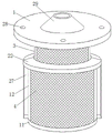
FIG. 1 is a schematic perspective view of the present invention;
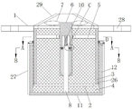
FIG. 2 is a schematic view of the internal structure of the present invention;
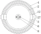
FIG. 3 is a schematic view of the structure of the plane A-A of FIG. 2 according to the present invention;
FIG. 4 is a schematic view of the structure of the plane B-B of FIG. 2 according to the present invention;
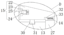
FIG. 5 is an enlarged view of FIG. 2 at C;
FIG. 6 is an enlarged view taken at D of FIG. 2 in accordance with the present invention;
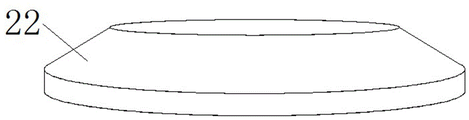
FIG. 7 is a schematic perspective view of a third annular plate according to the present invention; .
Reference numbers in the figures: 1. A circular plate; 2. a first annular plate; 3. a vertical plate; 4. a filter screen; 5. a transverse plate; 6. a circular tube; 7. a fan blade; 8. a round bar; 9. a chucking mechanism; 10. a first spring; 11. a base plate; 12. a fixing plate; 13. a second annular plate; 14. a fourth spring; 15. a clearing mechanism; 16. connecting blocks; 17. a vertical slot; 18. a second spring; 19. a cross bar; 20. clamping teeth; 21. a card slot; 22. a third annular plate; 23. a third spring; 24. inserting a rod; 25. gear shaping; 26. a slot; 27. a squeegee; 28. mounting holes; 29. a top shell; 30. a circular groove; 31. a movable block; 32. a chute; 33. a slide block.
Detailed Description
The technical solutions in the embodiments of the present invention will be clearly and completely described below with reference to the drawings in the embodiments of the present invention, and it is obvious that the described embodiments are only a part of the embodiments of the present invention, and not all of the embodiments. All other embodiments, which can be derived by a person skilled in the art from the embodiments given herein without making any creative effort, shall fall within the protection scope of the present invention.
Referring to fig. 1-7, the present invention provides a technical solution: a multifunctional filter element of a dust remover on a cement silo top comprises a circular plate 1, a plurality of mounting holes 28 are uniformly distributed on the top surface of the circular plate 1, the mounting holes 28 penetrate through the upper side wall and the lower side wall of the circular plate 1 to be arranged so as to facilitate the installation and fixation of the device, a circular hole is arranged at the center of the side wall of the circular plate 1, a first circular plate 2 is fixedly connected in the circular hole, two vertical plates 3 are fixedly connected on the bottom surface of the first circular plate 2 in a bilateral symmetry manner, the other side of each vertical plate 3 is fixedly connected with another first circular plate 2, two filter screens 4 are fixedly connected between the two first circular plates 2 in a front-back symmetry manner, the side walls of the filter screens 4 are respectively fixedly connected with the vertical plates 3 on two sides, a transverse plate 5 is fixedly connected between the two vertical plates 3, a circular tube 6 is movably connected at the center of the transverse plate 5, fan blades 7 are fixedly connected on the side wall of the circular tube 6 close to the top end, a circular rod 8 is movably connected with a circular rod 8 close to the top end, and is provided with a clamping mechanism 9, the clamping mechanism 9 comprises a connecting block 16, two connecting blocks 16 are fixedly connected on the side wall of the round rod 8 close to the top end in a bilateral symmetry manner, two vertical grooves 17 are symmetrically arranged on the side wall of the inner cavity of the round tube 6 in the bilateral symmetry manner, the connecting blocks 16 are movably connected with the vertical grooves 17, a movable hole is arranged on each connecting block 16, a second spring 18 is fixedly connected in the movable hole, the other end of the second spring 18 is fixedly connected with a cross rod 19, one end of the cross rod 19, far away from the second spring 18, extends out of the movable hole and is fixedly connected with a latch 20, two clamping grooves 21 are symmetrically arranged on the inner side wall of each vertical groove 17 in the up-down direction, the latch 20 and the clamping grooves 21 are mutually matched, the bottom plate 11 can be fixedly positioned according to gravity, the dust on the outer side filter screen 4 can be conveniently cleaned, the dust removal effect is good, a first spring 10 is fixedly connected on the top end of the round rod 8, and the other end of the first spring 10 is fixedly connected with the inner side wall of the round tube 6, the bottom end of the round rod 8 extends out of the round tube 6 and is fixedly connected with a bottom plate 11, the bottom plate 11 is arranged in a round shape, the top surface of the bottom plate 11 is fixedly connected with two fixed plates 12 in a bilateral symmetry manner, the top surfaces of the two fixed plates 12 are fixedly connected with a same second circular plate 13, another two filter screens 4 are fixedly connected between the second circular plate 13 and the bottom plate 11 in a front-back symmetry manner, the side walls of the filter screens 4 are fixedly connected with the fixed plates 12, the second circular plate 13 is provided with a clearing mechanism 15, the clearing mechanism 15 comprises a third circular plate 22, the third circular plate 22 is movably connected with the top surface of the second circular plate 13, the top surface of the third circular plate 22 is arranged in an inclined manner, so that the scraping operation of the filter screens 4 on the inner side wall is convenient, the top surface of the second circular plate 13 is provided with a round groove 30, the bottom surface of the third circular plate 22 is uniformly distributed and fixedly connected with a plurality of movable blocks 31, and the movable blocks 31 are movably connected with the round groove 30, two side holes are symmetrically formed in the inner side wall of the third circular plate 22 in the left-right direction, a third spring 23 is fixedly connected in each side hole, the other end of the third spring 23 is movably connected with an insert rod 24, the insert rod 24 is movably connected with the side holes, one end of the insert rod 24, which is far away from the third spring 23, is fixedly connected with an insert tooth 25, slots 26 are respectively formed in the side walls of the two vertical plates 3, which are far away from the circular rods 8, which are close to the bottom surface, the insert tooth 25 and the slots 26 are mutually matched, two scraping plates 27 are symmetrically and movably connected on the bottom surface of the third circular plate 22 in the left-right direction, so that the dust cleaning operation of the outer filter screen 4 is convenient, the use effect is good, two sliding grooves 32 are symmetrically formed in the bottom surface of the third circular plate 22 in the left-right direction, sliding blocks 33 are fixedly connected on the top surfaces of the scraping plates 27, the sliding blocks 33 are movably connected with the sliding grooves 32, fourth springs 14 are fixedly connected on the side walls of the sliding blocks 33, and the other ends of the fourth springs 14 are fixedly connected with the side walls of the sliding grooves 32, make to filter screen 4 clear away effectually, fixedly connected with top shell 29 on the top surface of the first ring board 2 of upside, the cross-section of top shell 29 is the setting of round platform shape, and the upside area of top shell 29 is greater than the setting of bottom surface area for the rotation of flabellum 7 is effectual, improves dust removal effect.
The working principle is as follows: when the device is used, firstly, the device is placed at a proper position on the top surface of a cement bin, the fixed mounting operation of the device is realized through an external bolt and a mounting hole 28, then a cement bin top dust remover is started through an external power supply, the internal gas is extracted under the action of the cement bin top dust remover, so that the dust is continuously adsorbed on the outer side wall of a filter screen 4, the gas is discharged from a top shell 29 through the filter screen 4, a fan blade 7 is driven to rotate in the gas flowing process, the fan blade 7 drives a bottom plate 11 to rotate through a circular tube 6 and a circular rod 8, the bottom plate 11 drives a fixing plate 12 and the filter screen 4 on the bottom plate to rotate together, so that the filter screen 4 can uniformly treat the dust, the dust removing effect is good, after the dust of the filter screen 4 on the fixing plate 12 is gathered to a certain amount, the latch 20 is separated from a clamping groove 21 on the upper side under the action of gravity, the connecting block 16 moves downwards in the vertical groove 17 and stretches the first spring 10, so that the latch 20 is clamped with the clamping groove 21 at the lower side of the vertical groove 17, thus realizing the repositioning, at the moment, the gear shaping 25 on the third circular plate 22 moves downwards together with the gear shaping to be inserted into the slot 26 on the fixed plate 12, realizing the positioning and fixing of the third circular plate 22, when the airflow drives the fan blades 7 to rotate, the bottom plate 11 drives the lower filter screen 4 to rotate, so that the scraper 27 scrapes off the dust on the filter screen 4, the dust filtering effect is improved, when the dust on the filter screen 4 is removed, the gravity is reduced, the bottom plate 11 is lifted under the action of the first spring 10, the third circular plate 22 avoids scraping the inner filter screen 4, the dust removal effect is improved, and the latch 20 is clamped into the clamping groove 21 on the upper side again, the dust processing operation is continued, and the processing effect is good.
Although embodiments of the present invention have been shown and described, it will be appreciated by those skilled in the art that changes, modifications, substitutions and alterations can be made in these embodiments without departing from the principles and spirit of the invention, the scope of which is defined in the appended claims and their equivalents.
Claims (3)
1. The utility model provides a multi-functional cement storehouse top dust remover filter core, includes plectane (1), its characterized in that: the novel fan blade is characterized in that a round hole is formed in the center of the side wall of the circular plate (1), a first circular plate (2) is fixedly connected in the round hole, two vertical plates (3) are fixedly connected on the bottom surface of the first circular plate (2) in a bilateral symmetry mode, the other side of each vertical plate (3) is fixedly connected with another first circular plate (2), two filter screens (4) are fixedly connected between the first circular plates (2) in a front-back symmetry mode, the side walls of the filter screens (4) are fixedly connected with the vertical plates (3) on the two sides respectively, a transverse plate (5) is fixedly connected between the two vertical plates (3), a circular tube (6) is movably connected in the center of the transverse plate (5), fan blades (7) are fixedly connected on the side wall of the circular tube (6) close to the top end, a circular rod (8) is movably connected in the inner cavity of the circular tube (6), and a clamping mechanism (9) is arranged on the circular rod (8) close to the top end, the clamping mechanism (9) comprises connecting blocks (16), the round rod (8) is fixedly connected with two connecting blocks (16) in a bilateral symmetry mode on the side wall close to the top end, two vertical grooves (17) are symmetrically formed in the inner cavity side wall of the round rod (6), the connecting blocks (16) are movably connected with the vertical grooves (17), a movable hole is formed in each connecting block (16), a second spring (18) is fixedly connected in the movable hole, the other end of the second spring (18) is fixedly connected with a cross rod (19), one end, far away from the second spring (18), of the cross rod (19) extends out of the movable hole and is fixedly connected with a clamping tooth (20), two clamping grooves (21) are symmetrically formed in the inner side wall of each vertical groove (17) in an up-down mode, the clamping tooth (20) is matched with the clamping grooves (21), and the top end of the round rod (8) is fixedly connected with a first spring (10), the other end of the first spring (10) is fixedly connected with the inner side wall of the round pipe (6), the bottom end of the round rod (8) extends out of the round pipe (6) and is fixedly connected with a bottom plate (11), the bottom plate (11) is arranged in a round shape, two fixing plates (12) are fixedly connected on the top surface of the bottom plate (11) in a bilateral symmetry manner, the top surfaces of the two fixing plates (12) are fixedly connected with a same second circular plate (13), another two filter screens (4) are fixedly connected between the second circular plate (13) and the bottom plate (11) in a front-back symmetry manner, the side walls of the filter screens (4) are fixedly connected with the fixing plates (12), a clearing mechanism (15) is arranged on the second circular plate (13), the clearing mechanism (15) comprises a third circular plate (22), the third circular plate (22) is movably connected with the top surfaces of the second circular plate (13), and the top surface of the third circular plate (22) is arranged in an inclined manner, two side holes are symmetrically formed in the inner side wall of the third circular plate (22), a third spring (23) is fixedly connected into each side hole, an inserted rod (24) is movably connected to the other end of the third spring (23), the inserted rod (24) is movably connected with the side holes, one end of the inserted rod (24), far away from the third spring (23), is fixedly connected with a gear shaping (25), two side walls, far away from the circular rod (8), of the vertical plates (3) are close to the bottom surface, slots (26) are formed in the side walls, mutually matched and arranged, two scraping plates (27) are symmetrically and movably connected to the bottom surface of the third circular plate (22), circular grooves (30) are formed in the top surface of the second circular plate (13), and a plurality of movable blocks (31) are fixedly connected to the bottom surface of the third circular plate (22) in an evenly distributed mode, the movable block (31) is movably connected with the circular groove (30), two sliding grooves (32) are symmetrically formed in the left and right of the bottom surface of the third circular plate (22), sliding blocks (33) are fixedly connected to the top surfaces of the scraping plates (27), the sliding blocks (33) are movably connected with the sliding grooves (32), a fourth spring (14) is fixedly connected to the side wall of each sliding block (33), and the other end of each fourth spring (14) is fixedly connected with the side wall of each sliding groove (32);
when the device is used, firstly, the device is placed at a proper position on the top surface of a cement bin, the fixed installation operation of the device is realized through an external bolt and a mounting hole (28), then, a cement bin top dust remover is started through an external power supply, the gas inside the dust remover is extracted under the action of the cement bin top dust remover, the dust is continuously adsorbed on the outer side wall of a filter screen (4), the gas is discharged from a top shell (29) through the filter screen (4), a fan blade (7) is driven to rotate in the gas flowing process, the fan blade (7) drives a bottom plate (11) to rotate through a circular tube (6) and a circular rod (8), the bottom plate (11) drives a fixing plate (12) and the filter screen (4) on the bottom plate to rotate together, the filter screen (4) is enabled to uniformly process the dust, the dust removal effect is good, and after the dust of the filter screen (4) on the fixing plate (12) is gathered to a certain amount, make latch (20) and draw-in groove (21) of upside break away from under the action of gravity, connecting block (16) moves down in erecting groove (17), and tensile first spring (10), make latch (20) and draw-in groove (21) block of erecting groove (17) downside, thereby realize repositioning, gear shaping (25) on third ring board (22) move down together and insert slot (26) on fixed plate (12) at this moment, realize the location fixed to third ring board (22), when air current drives flabellum (7) and rotates, bottom plate (11) drive downside filter screen (4) and rotate, make scraper blade (27) carry out the operation of scraping off the dust on filter screen (4), improve the filter effect to the dust, after dust on filter screen (4) is clear away, gravity reduces, make bottom plate (11) up the motion under first spring (10) effect at this moment, the inner side filter screen (4) of the third circular plate (22) is prevented from being scraped, the dust removal effect is improved, the latch (20) is clamped into the clamping groove (21) on the upper side again, the dust treatment operation is continued, and the treatment effect is good.
2. The filter element of the multifunctional cement silo top dust remover according to claim 1, wherein: a plurality of mounting holes (28) are uniformly distributed on the top surface of the circular plate (1), and the mounting holes (28) penetrate through the upper side wall and the lower side wall of the circular plate (1).
3. The filter element of the multifunctional cement silo top dust remover according to claim 1, wherein: upside fixedly connected with top shell (29) on the top surface of first ring board (2), the cross-section of top shell (29) is round platform shape setting, the upside area of top shell (29) is greater than the setting of bottom surface area.
Priority Applications (1)
| Application Number | Priority Date | Filing Date | Title |
|---|---|---|---|
| CN202110679685.7A CN113476964B (en) | 2021-06-18 | 2021-06-18 | Multifunctional filter element of dust remover on top of cement silo |
Applications Claiming Priority (1)
| Application Number | Priority Date | Filing Date | Title |
|---|---|---|---|
| CN202110679685.7A CN113476964B (en) | 2021-06-18 | 2021-06-18 | Multifunctional filter element of dust remover on top of cement silo |
Publications (2)
| Publication Number | Publication Date |
|---|---|
| CN113476964A CN113476964A (en) | 2021-10-08 |
| CN113476964B true CN113476964B (en) | 2022-08-09 |
Family
ID=77935590
Family Applications (1)
| Application Number | Title | Priority Date | Filing Date |
|---|---|---|---|
| CN202110679685.7A Active CN113476964B (en) | 2021-06-18 | 2021-06-18 | Multifunctional filter element of dust remover on top of cement silo |
Country Status (1)
| Country | Link |
|---|---|
| CN (1) | CN113476964B (en) |
Families Citing this family (3)
| Publication number | Priority date | Publication date | Assignee | Title |
|---|---|---|---|---|
| CN114413377A (en) * | 2021-12-31 | 2022-04-29 | 浙江上风高科专风实业股份有限公司 | Integrated form new trend purifying box |
| CN114642928B (en) * | 2022-04-29 | 2023-03-24 | 南通市征荣冷冻设备制造有限公司 | Air filtering device of refrigeration house matched with freeze drying equipment in sterile workshop |
| CN116983772B (en) * | 2023-09-26 | 2023-12-19 | 山西明普科技有限公司 | Air filtering device |
Citations (6)
| Publication number | Priority date | Publication date | Assignee | Title |
|---|---|---|---|---|
| FR2725379A1 (en) * | 1994-10-05 | 1996-04-12 | Denitral Sa | INSTALLATION FOR FILTERING A LIQUID OR A GAS CONTAINING SUSPENSION MATERIALS AND METHOD FOR IMPLEMENTING SAME |
| KR20110139168A (en) * | 2011-11-14 | 2011-12-28 | 한상관 | Method for producing gas using slurry and rock or method for constituting industrial water purifier or household water purifier and method for producing ballast water and beverage or food or drinking water or liquor or milk or soy or miso or saline or salt water How to extract only the ingredients, how to make the seawater fresh water, how to treat food waste or how to treat waste water, or how to clean sea water, river water or ground water, or to remove pollutant molecules that have escaped from fluid Construction method and device |
| CN209865066U (en) * | 2019-04-19 | 2019-12-31 | 济俊消防科技有限公司 | Breathing mask for fire rescue |
| CN112023490A (en) * | 2020-08-10 | 2020-12-04 | 郭新 | River wastewater treatment device |
| CN212594627U (en) * | 2020-05-19 | 2021-02-26 | 新昌县沃意科技有限公司 | Environment-friendly flue gas filter equipment convenient to change filter core |
| CN114307365A (en) * | 2022-01-07 | 2022-04-12 | 陈云 | Metal pollution solid-liquid separation device |
Family Cites Families (1)
| Publication number | Priority date | Publication date | Assignee | Title |
|---|---|---|---|---|
| IT1243121B (en) * | 1990-06-22 | 1994-05-24 | Padovan Snc Di Giorgio Mario E | FILTERING CYCLE FOR LIQUIDS CONTAINING SUSPENSION SOLIDS AND ROTARY FILTER SUITABLE FOR MAKING SUCH FILTERING CYCLE. |
-
2021
- 2021-06-18 CN CN202110679685.7A patent/CN113476964B/en active Active
Patent Citations (6)
| Publication number | Priority date | Publication date | Assignee | Title |
|---|---|---|---|---|
| FR2725379A1 (en) * | 1994-10-05 | 1996-04-12 | Denitral Sa | INSTALLATION FOR FILTERING A LIQUID OR A GAS CONTAINING SUSPENSION MATERIALS AND METHOD FOR IMPLEMENTING SAME |
| KR20110139168A (en) * | 2011-11-14 | 2011-12-28 | 한상관 | Method for producing gas using slurry and rock or method for constituting industrial water purifier or household water purifier and method for producing ballast water and beverage or food or drinking water or liquor or milk or soy or miso or saline or salt water How to extract only the ingredients, how to make the seawater fresh water, how to treat food waste or how to treat waste water, or how to clean sea water, river water or ground water, or to remove pollutant molecules that have escaped from fluid Construction method and device |
| CN209865066U (en) * | 2019-04-19 | 2019-12-31 | 济俊消防科技有限公司 | Breathing mask for fire rescue |
| CN212594627U (en) * | 2020-05-19 | 2021-02-26 | 新昌县沃意科技有限公司 | Environment-friendly flue gas filter equipment convenient to change filter core |
| CN112023490A (en) * | 2020-08-10 | 2020-12-04 | 郭新 | River wastewater treatment device |
| CN114307365A (en) * | 2022-01-07 | 2022-04-12 | 陈云 | Metal pollution solid-liquid separation device |
Also Published As
| Publication number | Publication date |
|---|---|
| CN113476964A (en) | 2021-10-08 |
Similar Documents
| Publication | Publication Date | Title |
|---|---|---|
| CN113476964B (en) | Multifunctional filter element of dust remover on top of cement silo | |
| CN113828075A (en) | Industrial bag-type dust collector | |
| CN209124321U (en) | Filter plant is used in a kind of production of antioxidant | |
| CN213468250U (en) | Anti-blocking structure of cyclone separator | |
| CN210496737U (en) | Separating mechanism for production of heat conduction materials | |
| CN211098216U (en) | A dust collector for carborundum production facility | |
| CN216259760U (en) | Stone material processing production is with dust high efficiency processing device | |
| CN217092628U (en) | Novel filter drum dust removal device | |
| CN216500684U (en) | Novel screening device for beryllium oxide ceramic substrate | |
| CN215310909U (en) | Cloth bag dust removal device for replacing dust collection bag | |
| CN215759458U (en) | Anti-blocking equipment for building drainage pipe | |
| CN202599134U (en) | Device for removing blockings from fire grate strip | |
| CN215390635U (en) | Anti-blocking vibrating screen | |
| CN214271685U (en) | Drainage device for bridge | |
| CN211384230U (en) | Filter bag device of dust remover | |
| CN210522044U (en) | Sack cleaner between trucd mixer | |
| CN217141067U (en) | Vertical thick liquids screening plant of art pottery | |
| CN220758533U (en) | Multitube ceramic dust remover | |
| CN215026963U (en) | Long-acting fold filter bag type dust collector | |
| CN215743688U (en) | Crushing and screening device for building | |
| CN220779351U (en) | Tea-seed oil filter equipment | |
| CN216572019U (en) | Air cleaner convenient to clearance | |
| CN110295772A (en) | A kind of pcb board workshop of high cleanliness | |
| CN219399375U (en) | Bag framework capable of rapidly discharging accumulated ash in bag for dust remover | |
| CN116873976B (en) | Preparation method of antimonous oxide |
Legal Events
| Date | Code | Title | Description |
|---|---|---|---|
| PB01 | Publication | ||
| PB01 | Publication | ||
| SE01 | Entry into force of request for substantive examination | ||
| SE01 | Entry into force of request for substantive examination | ||
| GR01 | Patent grant | ||
| GR01 | Patent grant |