CN113473444B - Communication method, device and system - Google Patents
Communication method, device and system Download PDFInfo
- Publication number
- CN113473444B CN113473444B CN202110633779.0A CN202110633779A CN113473444B CN 113473444 B CN113473444 B CN 113473444B CN 202110633779 A CN202110633779 A CN 202110633779A CN 113473444 B CN113473444 B CN 113473444B
- Authority
- CN
- China
- Prior art keywords
- access network
- network device
- radio access
- identifier
- message
- Prior art date
- Legal status (The legal status is an assumption and is not a legal conclusion. Google has not performed a legal analysis and makes no representation as to the accuracy of the status listed.)
- Active
Links
- 238000000034 method Methods 0.000 title claims abstract description 79
- 230000006854 communication Effects 0.000 title claims abstract description 78
- 238000004891 communication Methods 0.000 title claims abstract description 77
- 238000012545 processing Methods 0.000 description 89
- 238000013461 design Methods 0.000 description 56
- 230000006870 function Effects 0.000 description 45
- 230000005540 biological transmission Effects 0.000 description 41
- 238000010586 diagram Methods 0.000 description 26
- 230000015654 memory Effects 0.000 description 13
- 238000012795 verification Methods 0.000 description 9
- 238000004590 computer program Methods 0.000 description 6
- 230000006399 behavior Effects 0.000 description 4
- 230000004044 response Effects 0.000 description 4
- 230000003993 interaction Effects 0.000 description 3
- 238000012790 confirmation Methods 0.000 description 2
- 238000005516 engineering process Methods 0.000 description 2
- 230000003287 optical effect Effects 0.000 description 2
- 230000008569 process Effects 0.000 description 2
- 230000011664 signaling Effects 0.000 description 2
- 238000012546 transfer Methods 0.000 description 2
- 230000001413 cellular effect Effects 0.000 description 1
- 230000008859 change Effects 0.000 description 1
- 239000000835 fiber Substances 0.000 description 1
- 230000007774 longterm Effects 0.000 description 1
- 238000010295 mobile communication Methods 0.000 description 1
- 238000012986 modification Methods 0.000 description 1
- 230000004048 modification Effects 0.000 description 1
- 238000010606 normalization Methods 0.000 description 1
Images


Classifications
-
- H—ELECTRICITY
- H04—ELECTRIC COMMUNICATION TECHNIQUE
- H04W—WIRELESS COMMUNICATION NETWORKS
- H04W8/00—Network data management
- H04W8/02—Processing of mobility data, e.g. registration information at HLR [Home Location Register] or VLR [Visitor Location Register]; Transfer of mobility data, e.g. between HLR, VLR or external networks
- H04W8/08—Mobility data transfer
- H04W8/14—Mobility data transfer between corresponding nodes
-
- H—ELECTRICITY
- H04—ELECTRIC COMMUNICATION TECHNIQUE
- H04W—WIRELESS COMMUNICATION NETWORKS
- H04W36/00—Hand-off or reselection arrangements
- H04W36/0005—Control or signalling for completing the hand-off
- H04W36/0011—Control or signalling for completing the hand-off for data sessions of end-to-end connection
- H04W36/0033—Control or signalling for completing the hand-off for data sessions of end-to-end connection with transfer of context information
-
- H—ELECTRICITY
- H04—ELECTRIC COMMUNICATION TECHNIQUE
- H04W—WIRELESS COMMUNICATION NETWORKS
- H04W36/00—Hand-off or reselection arrangements
- H04W36/12—Reselecting a serving backbone network switching or routing node
-
- H—ELECTRICITY
- H04—ELECTRIC COMMUNICATION TECHNIQUE
- H04W—WIRELESS COMMUNICATION NETWORKS
- H04W36/00—Hand-off or reselection arrangements
- H04W36/24—Reselection being triggered by specific parameters
-
- H—ELECTRICITY
- H04—ELECTRIC COMMUNICATION TECHNIQUE
- H04W—WIRELESS COMMUNICATION NETWORKS
- H04W76/00—Connection management
- H04W76/20—Manipulation of established connections
Abstract
The embodiment of the invention discloses a communication method, a communication device and a communication system. The communication method comprises the steps that terminal equipment receives a context identifier sent by second wireless access network equipment and sends a first message containing the context identifier to the first wireless access network equipment, core network equipment receives a second message sent by the first wireless access network equipment and sends the message containing the context identifier to the second wireless access network equipment, and the core network equipment receives context information of the terminal equipment sent by the second wireless access network equipment and sends the context information to the first wireless access network equipment. Therefore, the communication between the first wireless access network equipment and the second wireless access network equipment is ensured, and the working efficiency is improved.
Description
Technical Field
The present invention relates to wireless communication technologies, and in particular, to a communication method, apparatus, and system in a wireless network.
Background
The third Generation Partnership project (3 rd Generation Partnership project,3 gpp) standard is discussing Light Connection (Light Connection) techniques. The terminal device may enter a light connection state under the direction of a Radio Access Network (RAN) device, which is referred to as an anchor radio Access Network device. The light connection state is a state between a Radio Resource Control (RRC) connected state and an Idle (Idle) state.
And obtaining the context identifier distributed by the anchor wireless access network equipment by the terminal equipment which enters the light connection state in the RRC connection state. The terminal device and the anchor wireless access network device both store context information related to the connection. And, the terminal device may select a camped cell based on the mobility of the cell reselection. And the terminal equipment sends the context identification to the service wireless access network equipment of the cell when the terminal equipment has a data transmission requirement. And the serving wireless access network equipment sends the context identifier to the anchor wireless access network equipment so as to acquire the context information of the terminal equipment from the anchor wireless access network equipment.
Generally, the above communication process is implemented between the anchor radio access network device and the serving radio access network device through a configured interface (e.g., an X2 interface). However, there may be no available interface between the anchor radio access network device and the serving radio access network device, and at this time, the anchor radio access network device and the serving radio access network device cannot communicate with each other.
Disclosure of Invention
Embodiments of the present invention provide a communication method, apparatus, and system in a wireless network, which can ensure effective communication between an anchor point wireless access network device and a serving wireless access network device, and especially improve the working efficiency of the system under the condition that there is no available interface between them.
In the embodiment of the present invention, the serving radio access network device is a first radio access network device, and the anchor radio access network device is a second radio access network device.
In one aspect, an embodiment of the present invention provides a communication method in a wireless network. The method comprises the following steps: the first radio access network equipment receives a first message containing a context identifier from the terminal equipment, wherein the context identifier contains an identifier of the second radio access network equipment and an identifier of the terminal equipment distributed by the second radio access network equipment. And the first radio access network equipment sends a second message to core network equipment, wherein the second message contains the context identifier. The first radio access network device receives context information of the terminal device from the core network device, wherein the context information of the terminal device is associated with an identifier of the terminal device. By the communication method provided by the embodiment, timely and effective communication can be ensured between the first radio access network device and the second radio access network device under the condition that no available interface exists, and the working efficiency of the system is improved.
In a possible design, the context identifier further includes PLMN information corresponding to the second radio access network device and/or an area identifier corresponding to the second radio access network device.
In a possible design, the first message and the second message further include PLMN information corresponding to the second radio access network device and/or an area identifier corresponding to the second radio access network device.
Through the possible design, the core network device can accurately determine the second radio access network device and send a message, so that the reliability of communication between the first radio access network device and the second radio access network device is improved.
In one possible design, the first message further includes indication information, where the indication information indicates that the area identifier corresponding to the first radio access network device is different from the area identifier corresponding to the second radio access network device. The method further comprises the following steps: and the first radio access network equipment sends an area identification request message to the terminal equipment. And the first radio access network equipment receives the area identification corresponding to the second radio access network equipment from the terminal equipment. Wherein the second message further includes an area identifier corresponding to the second radio access network device.
In one possible design, the method further includes: and the first radio access network equipment determines whether additional information needs to be acquired or not according to the context identifier, wherein the additional information comprises PLMN information corresponding to the second radio access network equipment and/or an area identifier corresponding to the second radio access network equipment. And if the additional information needs to be acquired, the first radio access network equipment sends an additional information request message to the terminal equipment. The first radio access network device receives the additional information from the terminal device. Wherein the second message further comprises the additional information.
Through the possible design, the information carried in the first message can be simplified, the transmission resources occupied by the first message are reduced, and the transmission efficiency is improved.
In one possible design, the additional information request message further includes preamble allocation information, where the preamble allocation information is used to indicate a preamble allocated to the terminal device. The method further comprises the following steps: the first radio access network device receives the preamble from the terminal device. And the first radio access network equipment sends the allocated transmission resources to the terminal equipment. The first radio access network device receives the additional information transmitted through the transmission resource from the terminal device.
In one possible design, the second message further includes an identification of the first radio access network device.
In one possible design, the method further includes: the first radio access network device receives authentication information from the terminal device. The second message further includes the authentication information and information of a serving cell of the first radio access network device serving the terminal device.
In one possible design, the sending, by the first radio access network device, the second message to the core network device includes: and the first radio access network equipment determines whether an interface between the first radio access network equipment and the second radio access network equipment exists according to the identifier of the second radio access network equipment. And if the interface does not exist, the first radio access network equipment sends the second message to the core network equipment.
In another aspect, an embodiment of the present invention provides a communication method in a wireless network. The method comprises the step that the second wireless access network equipment sends a context identifier to the terminal equipment, wherein the context identifier comprises the identifier of the second wireless access network equipment and the identifier of the terminal equipment distributed by the second wireless access network equipment. And the second radio access network equipment receives a message containing the context identification from the core network equipment. And the second radio access network equipment sends the context information of the terminal equipment to the core network equipment according to the message containing the context identifier, wherein the context information of the terminal equipment is associated with the identifier of the terminal equipment. By the communication method provided by the embodiment, timely and effective communication between the first radio access network device and the second radio access network device can be ensured, and the working efficiency of the system is improved.
In a possible design, the context identifier further includes PLMN information corresponding to the second radio access network device and/or an area identifier corresponding to the second radio access network device.
In a possible design, the message that includes the context identifier and is received by the second radio access network device from the core network device further includes PLMN information corresponding to the second radio access network device and/or an area identifier corresponding to the second radio access network device.
In a possible design, the message that includes the context identifier and is received by the second radio access network device from the core network device further includes at least one of an identifier of the first radio access network device, PLMN information corresponding to the first radio access network device, and an area identifier corresponding to the first radio access network device. Wherein the first radio access network device is a radio access network device serving the terminal device.
In one possible design, the method further includes: the second radio access network device also receives, from the core network device, authentication information of the terminal device and information of a serving cell of the first radio access network device serving the terminal device. And the second wireless access network equipment verifies the terminal equipment according to the verification information and the information of the service cell.
In one possible design, before the second radio access network device receives the message including the context identifier from the core network device, the method further includes: and the second wireless access network equipment sends control information to the terminal equipment, wherein the control information is used for indicating the terminal equipment to enter a light connection state.
In still another aspect, an embodiment of the present invention provides a communication method in a wireless network. The method comprises the step that the terminal equipment receives a context identifier from second wireless access network equipment, wherein the context identifier comprises the identifier of the second wireless access network equipment and the identifier of the terminal equipment distributed by the second wireless access network equipment. And the terminal equipment sends a first message to first radio access network equipment, wherein the first message contains the context identifier.
In a possible design, the context identifier further includes PLMN information corresponding to the second radio access network device and/or an area identifier corresponding to the second radio access network device.
In a possible design, the first message further includes PLMN indication information of the second radio access network device and/or an area identifier corresponding to the second radio access network device.
In one possible design, before the terminal device sends the first message to the first radio access network device, the terminal device further receives a second area identifier of the second radio access network device. And the terminal equipment receives the first area identification of the first radio access network equipment. And the terminal equipment judges whether the second area identification is the same as the first area identification.
In one possible design, the first message further includes indication information, where the indication information indicates that the first region identifier is different from the second region identifier.
In one possible design, the method further includes the terminal device receiving an area identification request message sent by the first radio access network device. And the terminal equipment responds to the area identification request message and sends the second area identification to the first radio access network equipment.
In a possible design, before the terminal device sends the first message to the first radio access network device, the terminal device further truncates the context identifier according to an instruction of the first radio access network device, where the first message includes a part of the truncated context identifier.
In a possible design, after the terminal device sends the first message to the first radio access network device, the method further includes that the terminal device receives an additional information request message from the first radio access network device, where the additional information includes at least one of an area identifier corresponding to the second radio access network device, PLMN information corresponding to the second radio access network device, and another part of context identifiers remaining after truncation. And the terminal equipment responds to the additional information request message and sends the additional information to the first radio access network equipment.
In one possible design, the additional information request message further includes preamble allocation information, where the preamble allocation information is used to indicate a preamble allocated to the terminal device. The method further comprises the following steps: and the terminal equipment sends the lead code to the first radio access network equipment. The terminal device receives transmission resource information from the first radio access network device, wherein the transmission resource information indicates transmission resources allocated to the terminal device by the first radio access network device. And the terminal equipment sends the additional information to the first radio access network equipment through the transmission resource.
In one possible design, the method further includes the terminal device sending authentication information of the terminal device to the first radio access network device.
In another aspect, an embodiment of the present invention provides a communication method in a wireless network. The method includes the first core network device receiving a second message from the first radio access network device. The second message contains a context identifier of the terminal device, wherein the context identifier contains an identifier of the second radio access network device and an identifier of the terminal device allocated by the second radio access network device. And the first core network equipment sends a third message to second core network equipment or the second wireless access network equipment. The third message includes the context identification. The first core network device receives context information of the terminal device from the second core network device or the second radio access network device, wherein the context information is associated with an identity of the terminal device. The first core network device sends the context information to the first radio access network device. By the communication method provided by the embodiment, the message between the first radio access network device and the second radio access network device can be forwarded through the core network device, thereby ensuring timely and effective communication.
In a possible design, the context identifier further includes PLMN information corresponding to the second radio access network device and/or an area identifier corresponding to the second radio access network device.
In a possible design, the second message and the third message further include PLMN information corresponding to the second radio access network device and/or an area identifier corresponding to the second radio access network device.
In one possible design, the second message and the third message further include authentication information of a terminal device and information of a serving cell of the first radio access network device serving the terminal device.
In one possible design, the second message further includes an identification of the first radio access network device.
In a possible design, the third message further includes at least one of an identifier of the first radio access network device, PLMN information corresponding to the first radio access network device, and an area identifier corresponding to the first radio access network device.
In another aspect, an embodiment of the present invention provides a communication method in a wireless network. The method comprises the second core network device receiving a fourth message containing the context identifier of the terminal device from the first radio access network device or the first core network device. Wherein the context identifier comprises an identifier of a second radio access network device and an identifier of the terminal device assigned by the second radio access network device. And the second core network equipment sends a message containing the context identifier to the second radio access network equipment. The second core network device receives context information of the terminal device from the second radio access network device, wherein the context information of the terminal device is associated with the identifier of the terminal device. The second core network device sends the context information to the first radio access network device or the first core network device. By the communication method provided by the embodiment, the message between the first radio access network device and the second radio access network device can be forwarded through the core network device, so that timely and effective communication is ensured.
In a possible design, the context identifier further includes PLMN information corresponding to the second radio access network device and/or an area identifier corresponding to the second radio access network device.
In a possible design, the fourth message and the message including the context identifier further include PLMN information corresponding to the second radio access network device and/or an area identifier corresponding to the second radio access network device.
In one possible design, the fourth message further includes an identification of the first radio access network device.
In one possible design, the fourth message further includes authentication information and information of a serving cell of the first radio access network device serving the terminal device.
In a possible design, the message including the context identifier further includes at least one of an identifier of a first radio access network device, PLMN information corresponding to the first radio access network device, and an area identifier corresponding to the first radio access network device, where the first radio access network device is an access network device serving the terminal device.
In one possible design, the method further includes the second core network device sending, to the second radio access network device, the authentication information of the terminal device and information of a serving cell of the first radio access network device serving the terminal device.
In another aspect, an embodiment of the present invention provides a radio access network device, where the radio access network device has a function of implementing a behavior of a first radio access network device in the foregoing method. The radio access network device includes a receiver, a processor, and a transmitter. The receiver is configured to receive a first message from a terminal device containing a context identification. The processor is configured to decode the first message including a context identifier, where the context identifier includes an identifier of a second radio access network device and an identifier of the terminal device assigned by the second radio access network device. The transmitter is configured to transmit a second message to a core network device, where the second message includes the context identifier. The receiver is further configured to receive context information of the terminal device from the core network device, where the context information of the terminal device is associated with an identifier of the terminal device.
In one possible design, the transmitter is further configured to transmit a zone identification request message to the terminal device. The receiver is further configured to receive, from the terminal device, an area identifier corresponding to the second radio access network device. Wherein the second message further includes an area identifier corresponding to the second radio access network device.
In one possible design, the processor is further configured to determine whether additional information needs to be acquired according to the identifier of the second radio access network device, where the additional information includes PLMN information corresponding to the second radio access network device and/or an area identifier corresponding to the second radio access network device. The transmitter is further configured to transmit an additional information request message to the terminal device if the processor determines that the additional information needs to be acquired. The receiver is further configured to receive the additional information from the terminal device. Wherein the second message further comprises the additional information.
In one possible design, the additional information request message further includes preamble allocation information, where the preamble allocation information is used to indicate a preamble allocated to the terminal device. The receiver is further configured to receive the preamble from the terminal device. The processor is further configured to allocate transmission resources for the terminal device. The transmitter is further configured to transmit the allocated transmission resource to the terminal device. The receiver receives the additional information transmitted through the transmission resource from the terminal device.
In one possible design, the receiver is further configured to receive authentication information from the terminal device. The second message further includes the authentication information and information of a serving cell of the terminal device served by the radio access network device.
In one possible design, the processor is further configured to determine whether an interface exists between the first radio access network device and the second radio access network device based on the identity of the second radio access network device. And if the interface does not exist, the transmitter is used for transmitting the second message to the core network equipment.
In another aspect, an embodiment of the present invention provides a radio access network device, where the radio access network device has a function of implementing a behavior of a second radio access network device in the foregoing method. The radio access network device includes a processor, a transmitter, and a receiver. The processor is used for distributing the identification of the terminal equipment to the terminal equipment. The transmitter is configured to transmit a context identifier to a terminal device, where the context identifier includes an identifier of the radio access network device and an identifier of the terminal device. The receiver is configured to receive a message including the context identifier from a core network device. The processor is further configured to determine context information of the terminal device in response to the message including the context identifier, wherein the context information of the terminal device is associated with the identifier of the terminal device. The transmitter is further configured to transmit context information of the terminal device to the core network device.
In one possible design, the receiver is further configured to receive, from the core network device, authentication information of the terminal device and information of a serving cell of the first radio access network device serving the terminal device. The processor is further configured to authenticate the terminal device according to the authentication information and the information of the serving cell.
In one possible design, the transmitter is further configured to transmit control information to the terminal device before the receiver receives the message including the context identifier from the core network device. The control information is used for indicating the terminal equipment to enter a light connection state.
The functions of the units in the radio access network device in the above aspects can also be implemented by executing corresponding software through hardware.
In still another aspect, an embodiment of the present invention provides a terminal device, where the terminal device executes the communication method in the wireless network according to the above aspect. The terminal device includes a receiver, a processor, and a transmitter. The receiver is configured to receive a context identification from a second radio access network device. The processor is configured to decode the context identifier, where the context identifier includes an identifier of the second radio access network device and an identifier of the terminal device assigned by the second radio access network device. The transmitter is configured to transmit a first message to a first radio access network device, where the first message includes the context identifier.
In one possible design, before the transmitter is configured to transmit the first message to the first radio access network device, the receiver is further configured to receive a second area identifier of the second radio access network device and a first area identifier of the first radio access network device. The processor is further configured to determine whether the second region identifier is the same as the first region identifier.
In one possible design, the receiver is further configured to receive an area identification request message sent by the first radio access network device. The processor controls the transmitter to transmit the second area identification to the first radio access network device in response to the area identification request message.
In one possible design, the processor is further configured to truncate the context identifier according to the indication of the first radio access network device, where the first message includes a part of the truncated context identifier.
In a possible design, the receiver is further configured to receive an additional information request message from the first radio access network device, where the additional information includes at least one of an area identifier corresponding to the second radio access network device, PLMN information corresponding to the second radio access network device, and another part of context identifiers remaining after the truncation. The processor is further configured to control the transmitter to transmit the additional information to the first radio access network device in response to the additional information request message.
In one possible design, the processor is further configured to decode an additional information request message, wherein the additional information request message further includes preamble allocation information indicating a preamble allocated to the terminal device. The transmitter is further configured to transmit the preamble to the first radio access network device. The receiver is further configured to receive transmission resource information from the first radio access network device, where the transmission resource information indicates transmission resources allocated by the first radio access network device for the terminal device. The transmitter is further configured to transmit the additional information to the first radio access network device over the transmission resources.
In one possible design, the transmitter is further configured to transmit the authentication information of the terminal device to the first radio access network device.
The functions of each unit in the terminal equipment can also be realized by executing corresponding software through hardware.
In another aspect, an embodiment of the present invention provides a core network device, where the core network device has a function of implementing a behavior of a first core network device in the foregoing method. The core network device includes a receiver, a processor, and a transmitter. The receiver is configured to receive a second message from the first radio access network device. The processor is configured to decode the second message. The second message contains the context identifier of the terminal equipment. Wherein the context identifier includes an identifier of a second radio access network device and an identifier of a terminal device assigned by the second radio access network device. The transmitter is configured to send a third message to a second core network device or the second radio access network device, where the third message includes the context identifier. The receiver is further configured to receive context information of the terminal device from the second core network device or the second radio access network device, wherein the context information is associated with an identity of the terminal device. The transmitter is further configured to transmit the context information to the first radio access network device.
In another aspect, an embodiment of the present invention provides a core network device, where the core network device has a function of implementing a second core network device behavior in the foregoing method. The core network device includes a receiver, a processor, and a transmitter. The receiver is configured to receive a fourth message from the first radio access network device or the first core network device. The processor is configured to decode the fourth message. The fourth message contains the context identifier of the terminal equipment, wherein the context identifier contains the identifier of the second wireless access network equipment and the identifier of the terminal equipment distributed by the second wireless access network equipment. The transmitter is configured to transmit a message including the context identifier to the second radio access network device. The receiver is further configured to receive context information of the terminal device from the second radio access network device, wherein the context information of the terminal device is associated with an identity of the terminal device. The transmitter is further configured to transmit the context information to the first radio access network device or the first core network device.
In one possible design, the transmitter is further configured to transmit, to the second radio access network device, authentication information of the terminal device and information of a serving cell of the first radio access network device serving the terminal device.
The functions of the units in the core network device in the above aspects can also be implemented by executing corresponding software through hardware.
In another aspect, an embodiment of the present invention provides a communication system, where the communication system includes the radio access network device, the terminal device, and the core network device in the foregoing aspects.
In yet another aspect, an embodiment of the present invention provides a computer storage medium for storing computer software instructions for the radio access network device, which includes a program designed to execute the above aspects.
In still another aspect, an embodiment of the present invention provides a computer storage medium for storing computer software instructions for the terminal device, which includes a program designed to execute the above aspects.
In another aspect, an embodiment of the present invention provides a computer storage medium for storing computer software instructions for the core network device, which includes a program designed to execute the above aspects.
According to the technical scheme provided by the embodiment of the invention, the first radio access network equipment and the second radio access network equipment are communicated through the core network equipment, so that the communication can be still timely and effectively realized under the condition that no available interface exists between the first radio access network equipment and the second radio access network equipment, and the working efficiency of the system is improved.
Drawings
In order to more clearly illustrate the technical solutions of the embodiments of the present invention, the drawings used in the description of the embodiments will be briefly introduced below. It is obvious that the drawings described below are only some embodiments of the invention, and that other drawings can be derived from these drawings within reasonable scope for a person skilled in the art.
Fig. 1A is a schematic diagram of a possible communication network scenario provided in an embodiment of the present invention;
fig. 1B is a schematic diagram of another possible communication network scenario provided by an embodiment of the present invention;
fig. 2 is a schematic diagram of a communication method according to an embodiment of the present invention;
fig. 3 is a schematic diagram of a communication method according to another embodiment of the present invention;
fig. 4 is a schematic structural diagram of a radio access network device according to an embodiment of the present invention;
fig. 5 is a schematic structural diagram of another possible structure of a radio access network device according to an embodiment of the present invention;
fig. 6 is a schematic diagram of another possible structure of a radio access network device according to an embodiment of the present invention;
fig. 7 is a schematic diagram of another possible structure of a radio access network device according to an embodiment of the present invention;
fig. 8 is a schematic diagram of a possible structure of a terminal device according to an embodiment of the present invention;
fig. 9 is a schematic diagram of another possible structure of a terminal device according to an embodiment of the present invention;
fig. 10 is a schematic structural diagram of a core network device according to an embodiment of the present invention;
fig. 11 is a schematic structural diagram of another possible core network device according to an embodiment of the present invention;
fig. 12 is a schematic structural diagram of another possible core network device according to an embodiment of the present invention;
fig. 13 is a schematic diagram of another possible structure of a core network device according to an embodiment of the present invention.
Detailed Description
The technical solution in the embodiments of the present invention will be clearly and completely described below with reference to the accompanying drawings. It should be apparent that the described embodiments are only some of the embodiments of the present invention, and not all of the embodiments. It is understood that other embodiments obtained by combining technical features of the embodiments or between the embodiments by those skilled in the art without generating ambiguity or contradiction also belong to the protection scope of the present invention.
The proposed solution of the embodiment of the present invention is based on the communication system 100 shown in fig. 1A or fig. 1B. The communication system 100 includes at least one core Network device, at least two Radio Access Network (RAN) devices, and at least one terminal device. Each of the radio access network devices covers at least one cell. The at least two radio access network devices include an anchor radio access network device and at least one serving radio access network device. The radio access network equipment is connected with the core network equipment through a communication interface. The communication interface may be an S1 interface. The core network device may be a device having a mobility management function.
The anchor radio access network device may instruct the terminal device to enter a light connection state and assign a context identifier to the terminal device. The light connection state may be a sub-state of a Radio Resource Control (RRC) connection state, an enhanced state of an idle (idle) state, or an independent state. The lightly connected state may also be referred to as an inactive state, a deactivated state, a low active state, a low overhead state, and the like. The embodiment of the invention does not specifically limit the form and name of the light connection state. The terminal device in a light connection state holds context information and has mobility to perform cell reselection.
And the anchor point wireless access network equipment and the terminal equipment entering the light connection state both store the context information of the terminal equipment. The context information may include connection configuration parameters between the anchor radio access network device and the terminal device.
If the terminal device entering the light connection state does not change the resident cell, when the terminal device has a data transmission requirement, the stored context information can be used for recovering the RRC connection between the terminal device and the anchor point wireless access network device, thereby avoiding the signaling load in the RRC connection reestablishment process.
If the terminal device entering the light connection state changes the resident cell, the anchor wireless access network device is not required to make a handover indication, but the terminal device determines the resident cell on its own based on cell reselection criteria. For example, the terminal device may choose to camp on a cell with better signal quality or higher strength. The terminal device is served in the camped cell by a serving radio access network device. When the terminal device has a data transmission requirement, the terminal device may establish RRC connection with the serving radio access network device, so as to obtain a data transmission service provided by the serving radio access network device.
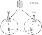
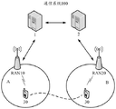
Specifically, as shown in fig. 1A and 1B, the communication system 100 includes a radio access network device 10, a radio access network device 20, and a terminal device 30. Wherein the radio access network device 10 is an anchor radio access network device and the radio access network device 20 is a serving radio access network device. The radio access network device 10 controls cell a. The radio access network device 20 controls cell B. It is to be understood that the radio access network device 10 and the radio access network device 20 may control more cells, not limited to the cell a and the cell B. The terminal device 30 enters a light connection state under the direction of the radio access network device 10. Thereafter, the terminal device 30 moves to cell B. In cell B, the terminal device is provided with a data transmission service by the radio access network device 20.
In the solution of the embodiment of the present invention, the radio access network device 10 and the radio access network device 20 both have a communication interface, such as an S1 interface, with the same core network device, and thus can be controlled by the same core network device. For example, in the communication system 100 shown in fig. 1A, the radio access network device 10 and the radio access network device 20 both have a communication interface with the core network device 1, and thus can be controlled by the core network device 1.
In the solution of the embodiment of the present invention, the radio access network device 10 and the radio access network device 20 may also have communication interfaces with different core network devices, and thus are controlled by different core network devices respectively. For example, in the communication system 100 shown in fig. 1B, the radio access network device 10 has a communication interface with the core network device 1, and the radio access network device 20 has a communication interface with the core network device 2.
Typically, each core network device is responsible for managing at least one area of mobility management. For example, the mobility management Area may be a Tracking Area (TA), and each core network device corresponds to at least one Tracking Area. Each TA may correspond to a Tracking Area Code (TAC), which may be used to identify the corresponding TA. Of course, the Area may also be a Routing Area (RA) corresponding to the Routing Area Code (RAC) or a Location Area (LA) corresponding to the Location Area Code (LAC). The core network device 1 and the core network device 2 can communicate with each other.
In the embodiment of the present invention, the communication System 100 may be a Global System for Mobile communications (GSM) System, a Code Division Multiple Access (CDMA) System, a Wideband Code Division Multiple Access (WCDMA) System, a General Packet Radio Service (GPRS), a Long Term Evolution (LTE) System, a Frequency Division Duplex (FDD) System, a Time Division Duplex (TDD), a Universal Mobile Telecommunications System (UMTS), other wireless communication systems using Orthogonal Frequency Division (OFDM) technology, and the like. The system architecture and the service scenario described in the embodiment of the present invention are for more clearly illustrating the technical solution of the embodiment of the present invention, and do not form a limitation on the technical solution provided in the embodiment of the present invention, and it can be known by those skilled in the art that the technical solution provided in the embodiment of the present invention is also applicable to similar technical problems along with the evolution of the network architecture and the appearance of a new service scenario.
In an embodiment of the present invention, the radio access network device (e.g., the radio access network device 10, 20) may be configured to provide a terminal device with a wireless communication function. The radio access network devices may include various forms of macro base stations, micro base stations (also referred to as small stations), relay stations, access points, and the like. The radio access network device may be a Base Station (BTS) in GSM or CDMA, a Base Station (NodeB, NB) in WCDMA, an evolved Node B (eNB or e-NodeB) in LTE, and a corresponding next Generation Base Station (next Generation Node B, gNB) in a 5G network. For convenience of description, in all embodiments of the present invention, the above-mentioned apparatus for providing a wireless communication function for a terminal device is collectively referred to as a radio access network device.
In the embodiment of the present invention, the Terminal device (e.g., the Terminal device 30) may also be referred to as a User Equipment (UE), a Mobile Station (MS), a Mobile Terminal (Mobile Terminal), and the like, and the Terminal device may communicate with one or more core networks through a Radio Access Network (RAN), for example, the Terminal device may be a Mobile phone (or a "cellular" phone), a computer with a Mobile Terminal, and the like, for example, the Terminal device may also be a portable, pocket, handheld, computer-embedded, or vehicle-mounted Mobile device, and they exchange languages and/or data with the RAN. The embodiment of the present invention is not particularly limited.
In the embodiment of the present invention, the core network device controls one or more radio access network devices, and may perform unified management on resources in the system, and may also configure resources for the terminal device, and the like. For example, the Radio access Network device may be a Node B and a Radio Network Controller (RNC) in the UMTS system, and the core Network device may be a Serving GPRS Support Node (SGSN) and a Gateway GPRS Support Node (GGSN). For another example, the radio access network device may be an eNB in an LTE system, and the core network device may be a Mobility Management Entity (MME). For another example, the core network device may be a wireless network cross-system cooperative controller, and the like, which is not specifically limited in the embodiment of the present invention.
It should be noted that the number of network elements included in the communication system 100 shown in fig. 1A and fig. 1B is merely an example, and the embodiment of the present invention is not limited thereto. Furthermore, in the communication system 100 shown in fig. 1A or fig. 1B, although the core network devices 1 and 2, the radio access network devices 10 and 20, and the terminal device 30 are shown, the communication system 100 may not be limited to include the above network elements, and may also include a device for carrying a virtualized network function, and the like, which are not described in detail herein.
When the terminal device needs to establish an RRC connection with a serving radio access network device, the serving radio access network device may obtain context information of the terminal device from the anchor radio access network device. Thus, the serving radio access network device needs to communicate with the anchor radio access network device to complete the transfer of the context information.
Generally, an interface is configured between radio access network devices. And the anchor wireless access network equipment and the service wireless access network equipment realize communication through a configured interface. However, a communication interface may not be configured between the radio access network devices due to area division, low power consumption, or the like, or there may be a case where an interface is unavailable. At this time, the anchor radio access network device and the serving radio access network device cannot communicate with each other, which may cause the terminal device not to obtain a data transmission service in time after cell reselection, thereby reducing working efficiency.
Based on the above technical problems, in the communication method in the wireless network provided in the embodiments of the present invention, under the condition that the anchor point wireless access network device and the serving wireless access network device cannot directly communicate through the interface, the core network device is used to perform message processing through the method described in the embodiments of the present invention, thereby ensuring timely and effective information acquisition and data transmission, and improving work efficiency. Of course, based on the communication method in the wireless network provided by the embodiment of the present invention, the method provided by the embodiment of the present invention can be adopted no matter whether the anchor point wireless access network device and the serving wireless access network device have communication interfaces, so as to achieve the purpose of flow normalization under different conditions.
For ease of description and to avoid unnecessary limitations, the serving radio access network device will be referred to hereinafter as the first radio access network device and the anchor radio access network device will be referred to as the second radio access network device.
Fig. 2 is a diagram illustrating a communication method in a wireless network according to an embodiment of the present invention. In this embodiment, as shown in fig. 1A, the first radio access network device and the second radio access network device are controlled by the same core network device. The method provided by the present embodiment is described in detail from the perspective of interaction with fig. 2.
S201, the second wireless access network equipment sends the context identifier to the terminal equipment.
Wherein the context identifier comprises an identifier of a second radio access network device and an identifier of the terminal device assigned by the second radio access network device. The context identifier may be used to identify the terminal device, and may also be used to identify context information of the terminal device.
The context identifier may be an independent identifier consisting of a continuous string of characters. The context identifier may uniquely identify the terminal device within a local Area, for example, within a Tracking Area (Tracking Area) or within a Public Land Mobile Network (PLMN). The context identifier may also uniquely identify the terminal device on a global scale.
The context identifier may be a continuous string of identifiers of the second radio access network device and the terminal device. The context identifier may also be a non-continuous string composed of the identifier of the second radio access network device and the identifier of the terminal device. The identity of the second radio access network device included in the context identity may consist of an area identity and an identity of the second radio access network device within the area. The embodiment of the present invention is not particularly limited to this.
Optionally, the context identifier further includes PLMN information corresponding to the second radio access network device and/or an area identifier corresponding to the second radio access network device. The Area identifier may be a Tracking Area Code (TAC), a Routing Area Code (RAC), or a Location Area Code (LAC). The PLMN information corresponding to the second radio access network device and/or the area identifier corresponding to the second radio access network device is used to determine, in a global scope, a core network device to which the second radio access network device belongs.
Optionally, the second radio access network device sends control information to the terminal device, and instructs the terminal device to enter a light connection state. And the second wireless access network equipment and the terminal equipment both save the context information of the terminal equipment. Wherein the context information of the terminal device is associated with an identity of the terminal device.
The context information may comprise connection configuration parameters between the second radio access network device and the terminal device. Specifically, the connection configuration parameter may include a radio bearer configuration of the terminal device, where the radio bearer configuration includes a signaling radio bearer configuration and/or a data radio bearer configuration. The context information may also contain key information for use in encrypted transmissions or in generating terminal device authentication information.
S202, the terminal device receives the context identifier from the second radio access network device and sends a first message containing the context identifier to the first radio access network device.
In particular, the terminal device is camped on a cell served by the first radio access network device based on a cell reselection. The terminal device may send a first message containing the context identifier to the first radio access network device for the following reasons: the terminal device needs to report the information of the current cell to the second radio access network device. Or, the terminal device needs the first radio access network device to provide a data transmission service.
Optionally, when the terminal device sends the context identifier to the first radio access network device through the first message, the terminal device truncates the context identifier according to the indication of the first radio access network device, and sends only a part of the truncated context identifier. This is because sending the complete context identifier may result in the first message being too large, so that the terminal device cannot successfully complete sending the first message when the signal quality is poor. Therefore, in order to ensure that the first message can be successfully sent, the first radio access network device may instruct the terminal device to send only a part of the truncated context identifier. For example, the context identifier is 40 bits, and the first radio access network may instruct the terminal device to transmit only 24 bits of the context identifier.
The first message may further include PLMN information corresponding to the second radio access network device and/or an area identifier corresponding to the second radio access network device. The PLMN information corresponding to the second radio access network device and/or the area identifier corresponding to the second radio access network device may be included in the context identifier and carried in the first message, or may be carried in the first message independently of the context identifier.
Optionally, the terminal device obtains a PLMN corresponding to the second radio access network device. And after the terminal equipment moves to a cell served by the first radio access network equipment, determining PLMN information of the second radio access network equipment according to the PLMN broadcasted in the cell. For example, the PLMN corresponding to the second radio access network device is 103, the PLMNs broadcast in the cell served by the first radio access network device include 101, 102, 103, and 104, and the 4 PLMNs correspond to 4 pieces of PLMN information of 0,1,2, and 3, respectively, in sequence. The PLMN information carried in the first message by the terminal device is 3. The first radio access network device thus determines that the PLMN corresponding to the second radio access network device is 103. Therefore, the first message can be simplified, and the success rate of the first message transmission is ensured.
Optionally, the first message further includes area identifier indication information. The area identifier indication information is used to indicate whether the area identifier corresponding to the first radio access network device is the same as the area identifier corresponding to the second radio access network device. In this embodiment, the area identifier indication information indicates that the area identifier corresponding to the first radio access network device is the same as the area identifier corresponding to the second radio access network device. For example, if the area identifier corresponding to the second radio access network device is 1235, and the area identifier corresponding to the first radio access network device is also 1235, the terminal device sets the area identifier indication information to be the same, and sends the area identifier indication information to the first radio access network device. And the first radio access network equipment determines that the area identifier corresponding to the second radio access network equipment is 1235 according to the area identifier indication information.
Optionally, the terminal device further sends verification information to the first radio access network device. The terminal device may send the authentication information as a separate message together with the first message. Alternatively, the terminal device may include the authentication information in the first message and transmit the authentication information. The authentication information is used for the second radio access network device to authenticate the terminal device.
S203, the first radio access network device receives the first message sent by the terminal device, and sends a second message to a core network device, where the second message includes the context identifier.
And after receiving the first message, the first radio access network equipment decodes the first message to acquire the information carried in the first message.
Optionally, the first radio access network device determines whether it needs to request the terminal device to send additional information according to the context identifier included in the first message. The additional information includes at least one of an area identifier corresponding to the second radio access network device, PLMN information corresponding to the second radio access network device, and another part of context identifiers remaining after the truncation. For example, the first radio access network device determines whether an area identifier and/or PLMN information corresponding to the second radio access network device is stored, and if not, determines that the area identifier and/or PLMN information corresponding to the second radio access network device needs to be acquired. For another example, the first radio access network device determines whether an interface between the first radio access network device and the second radio access network device exists according to the identifier of the second radio access network device, and if the interface does not exist, it determines that the area identifier and/or the PLMN information corresponding to the second radio access network device needs to be acquired. As another optional mode, when the first message further includes the area identifier indication information, the first radio access network device determines that the additional information needs to be acquired.
If the first radio access network device determines that the additional information needs to be acquired, performing the following optional steps:
s2021, the first radio access network device sends an additional information request message to the terminal device.
Specifically, the additional information request message is sent to the terminal device through a common control channel. The additional information request message may contain preamble allocation information of the terminal device. The preamble allocation information indicates the preamble allocated to the terminal device by the first radio access network device. Thus, the terminal device can transmit additional information according to the preamble allocation information.
The additional information request message may further include indication information. The indication information comprises at least one of PLMN request information, area identification request information and the other part of context identification request information left after truncation. And the terminal equipment determines the information to be sent according to the indication information.
S2022, the terminal device receives the additional information request message, and sends the additional information to the first radio access network device according to the additional information request message.
Specifically, the terminal device sends a preamble to the first radio access network device according to the preamble allocation information. And the first radio access network equipment allocates transmission resources for the terminal equipment according to the lead code and sends transmission resource information. And the terminal equipment sends the additional information through the transmission resource. The additional information may be sent in a message. And sending the message containing the additional information to the first radio access network equipment through a common control channel.
Optionally, the first radio access network device combines a part of the truncated context identifier included in the first message and another part of the remaining context identifier obtained by the additional information after truncation into a complete context identifier.
And the first radio access network equipment carries the complete context identification in the second message.
The second message may further include PLMN information corresponding to the second radio access network device and/or an area identifier corresponding to the second radio access network device. The PLMN information corresponding to the second radio access network device and/or the area identifier corresponding to the second radio access network device may be included in the context identifier, or may be included in the first message and carried in the second message in a manner independent of the context identifier. The PLMN information corresponding to the second radio access network device and/or the area identifier corresponding to the second radio access network device may also be obtained by the first radio access network device through the additional information and carried in the second message.
The area identifier corresponding to the second radio access network device included in the second message may also be determined by the first radio access network device according to the indication information in the first message and carried in the second message.
Optionally, the first radio access network device stores PLMN information corresponding to the second radio access network device and/or an area identifier corresponding to the second radio access network device. And the first radio access network device carries the stored PLMN information corresponding to the second radio access network device and/or the area identifier corresponding to the second radio access network device in the second message.
Optionally, the second message further includes the verification information and information of a serving cell of the first radio access network device serving the terminal device. The information of the serving Cell may include at least one of a Physical Cell Identifier (PCI), a frequency Band (Band), and a Cell Global Identifier (ECGI) of the serving Cell. The information of the serving cell is used together with the authentication information for the second radio access network device to authenticate the terminal device.
Optionally, the second message further includes an identifier of the first radio access network device. Therefore, the core network equipment can determine the sender of the second message and can accurately send the second message back to the first radio access network equipment after receiving the return message.
The second message further contains an identification of the second radio access network device. Wherein the second message may include a content portion and a routing portion. The identification of the second radio access network device may be included in a routing information portion of the second message. Thus, the core network device may specify a recipient of the second message without reading the context identifier included in the second message.
The method has the advantages that the sender and/or the receiver of the second message are/is directly marked, and the probability of message forwarding failure is reduced.
It can be understood that the second message may not include the identifier of the first radio access network device and the identifier of the second radio access network device, but is determined by the core network device itself, and in a case that accuracy is ensured, by doing so, message content can be simplified, transmission efficiency can be improved, and network resources can be saved.
Optionally, the first radio access network device determines, according to the identifier of the second radio access network device, whether an interface exists between the first radio access network device and the second radio access network device. For example, the first radio access network device may determine whether an interface exists through an internally stored list of radio access network devices. Or, the first wireless access network device determines the availability of the interface with the second wireless network device according to the internally stored configuration parameters. When the interface does not exist between the first radio access network device and the second radio access network device, the first radio access network device sends the second message to the core network device.
S204, the core network device receives the second message and sends a third message containing the context identifier to the second wireless access network device.
Optionally, the third message further includes PLMN information corresponding to the second radio access network device and/or an area identifier corresponding to the second radio access network device. The PLMN information corresponding to the second radio access network device and/or the area identifier corresponding to the second radio access network device may be included in the context identifier, or may be included in the second message and carried in the third message in a manner independent of the context identifier.
Optionally, the third message further includes at least one of an identifier of the first radio access network device, PLMN information corresponding to the first radio access network device, and an area identifier corresponding to the first radio access network device. The above information is used for determining the first radio access network device when the core network device sends a return message.
Optionally, step S2041 may also be included, where the core network device sends, to the second radio access network device, verification information of the terminal device and information of a serving cell where the first radio access network device serves the terminal device. The information may be transmitted in the third message, or may be transmitted independently of the third message.
S205, the second radio access network device sends the context information of the terminal device to the core network device according to the third message containing the context identifier.
Wherein the context information of the terminal device is associated with an identity of the terminal device.
The context information may further include an acknowledgement message, where the acknowledgement message is used to feed back to the first radio access network device that the second radio access network device has learned the current location of the terminal device.
The context information may also include connection configuration parameters for the terminal device to establish an RRC connection with the first radio access network device.
Optionally, the second radio access network device further receives the verification information sent by the core network device and information of a serving cell where the first radio access network device serves the terminal device, and verifies the terminal device according to the verification information and the information of the serving cell.
S206, the core network device sends the context information to the first radio access network device.
Optionally, the first radio access network device determines, according to the context information, that the second radio access network device already knows the current location of the terminal device.
Optionally, the first radio access network device establishes an RRC connection with the terminal device using the context information, and provides a data transmission service for the terminal device.
It should be noted that steps S205 and S206 are optional steps.
In the embodiment of the present invention, when there is no available interface between the first radio access network device and the second radio access network device, the core network device is used as a medium for message transmission, so that communication between the radio access network devices can still be achieved, and the working efficiency of the system is improved.
Fig. 3 is a diagram illustrating a communication method in a wireless network according to another embodiment of the present invention. In this embodiment, as shown in fig. 1B, the first radio access network device and the second radio access network device are respectively controlled by different core network devices. In this embodiment, the first radio access network device is controlled by a first core network device, and the second radio access network device is controlled by a second core network device. The method provided by the present embodiment is described in detail from the perspective of interaction with fig. 3.
S301, the second wireless access network equipment sends the context identifier to the terminal equipment.
S302, the terminal device receives the context identifier from the second radio access network device, and sends a first message containing the context identifier to the first radio access network device.
Optionally, the first message includes indication information. The indication information is used to indicate whether the area identifier corresponding to the first radio access network device is the same as the area identifier corresponding to the second radio access network device. In this embodiment, the indication information indicates that the area identifier corresponding to the first radio access network device is different from the area identifier corresponding to the second radio access network device. For example, if the area identifier corresponding to the second radio access network device is 1236, and the area identifier corresponding to the first radio access network device is 1235, the terminal device sets the indication information to be different, and sends the indication information to the first radio access network device.
S303, the first radio access network device receives the first message sent by the terminal device, and sends a second message to the first core network device, where the second message includes the context identifier.
And after receiving the first message, the first radio access network equipment decodes the first message to acquire the information carried in the first message.
Optionally, the first radio access network device determines, according to the indication information included in the first message, that the area identifiers corresponding to the second radio access network device are different. At this time, the first radio access network device needs to acquire the complete area identifier corresponding to the second radio access network device. Thus, the first radio access network device performs the following steps:
s3021, the first radio access network device sends an area identifier request message to the terminal device.
S3022, the terminal device receives the area identifier request message, and sends an area identifier corresponding to the second radio access network device to the first radio access network device.
Therefore, the first radio access network device obtains the area identifier corresponding to the second radio access network device through the above process and carries the area identifier in the second message.
S304, the first core network device receives the second message, and sends a fourth message containing the context identifier to the second core network device.
Optionally, the fourth message further includes PLMN information corresponding to the second radio access network device and/or an area identifier corresponding to the second radio access network device. The PLMN information corresponding to the second radio access network device and/or the area identifier corresponding to the second radio access network device is included in the context identifier, or is included in the second message and carried in the fourth message in a manner independent of the context identifier.
The fourth message may also contain an identification of the first radio access network device. Therefore, the first core network device and the second core network device can accurately send back to the first radio access network device after receiving the return message.
Optionally, the fourth message further includes authentication information and information of a serving cell of the first radio access network device serving the terminal device.
S305, the second core network device receives the fourth message, and sends a message containing the context identifier to the second radio access network device.
S306, the second radio access network device sends the context information of the terminal device to the second core network device according to the message containing the context identifier.
S307, the second core network device sends the context information to the first core network device.
S308, the first core network device sends the context information to the first radio access network device.
It should be noted that relevant contents not described in detail in steps S301 to S308 may refer to corresponding parts of steps S201 to S206 in the method shown in fig. 2, and are not described again here. Wherein, steps S306-S308 are optional.
In the embodiment of the present invention, when there is no available interface between the first radio access network device and the second radio access network device, the respective core network devices are used as media for message transmission, so that communication between the radio access network devices can still be achieved, and the working efficiency of the system is improved.
The above description mainly introduces the scheme provided by the embodiment of the present invention from the perspective of interaction between various devices. It is to be understood that each device, such as a terminal device, an access network device, a core network device, etc., contains a hardware structure and/or a software module for executing each function in order to realize the functions. Those of skill in the art will readily appreciate that the invention is capable of being implemented as hardware or a combination of hardware and computer software in connection with the exemplary elements and algorithm steps described in connection with the embodiments disclosed herein. Whether a function is performed in hardware or computer software drives hardware depends upon the particular application and design constraints imposed on the solution. Skilled artisans may implement the described functionality in varying ways for each particular application, but such implementation decisions should not be interpreted as causing a departure from the scope of the present invention.
Fig. 4 shows a schematic diagram of a possible structure of the radio access network device involved in the above embodiments. It should be noted that the radio access network device is capable of executing the method in the foregoing embodiment, and therefore, specific details thereof may refer to the description in the foregoing embodiment, and for the sake of brevity, the same contents are not described in detail below. The radio access network device may be the radio access network device 10 shown in fig. 1A or 1B. The radio access network device is a first radio access network device serving the terminal device. The radio access network device includes a receiving unit 401, a processing unit 402, and a transmitting unit 403.
The receiving unit 401 is configured to receive a first message containing a context identifier from a terminal device.
The processing unit 402 is configured to decode the first message including the context identifier, where the context identifier includes an identifier of a second radio access network device and an identifier of the terminal device assigned by the second radio access network device.
The sending unit 403 is configured to send a second message to a core network device, where the second message includes the context identifier.
The receiving unit 401 is further configured to receive context information of the terminal device from the core network device, where the context information of the terminal device is associated with an identifier of the terminal device.
Optionally, the processing unit 402 is further configured to truncate the context identifier according to the instruction of the first radio access network device, and control the sending unit 403 to send only a part of truncated context identifiers.
Optionally, the processing unit 402 is further configured to decode the context identifier, and acquire PLMN information corresponding to the second radio access network device and/or an area identifier corresponding to the second radio access network device, where the PLMN information is included in the context identifier. The area identifier may be TAC, RAC, or LAC.
The processing unit 402 may be further configured to decode the first message, and acquire PLMN information corresponding to the second radio access network device and/or an area identifier corresponding to the second radio access network device, where the PLMN information is included in the first message. As described in step S202 shown in fig. 2, the PLMN information corresponding to the second radio access network device and/or the area identifier corresponding to the second radio access network device may be included in the context identifier and carried in the first message, or may be carried in the first message independently of the context identifier.
Optionally, the processing unit 402 is further configured to obtain PLMN information corresponding to the second radio access network device by decoding the first message. Specifically, the processing unit 402 may obtain the PLMN corresponding to the second radio access network device as described in step S202 shown in fig. 2, which is not described herein again.
Optionally, the processing unit 402 is further configured to obtain the indication information by decoding the first message. The indication information indicates whether the area identifier corresponding to the first radio access network device is the same as the area identifier corresponding to the second radio access network device. If the indication of the indication information is the same, the processing unit 402 determines that the area identifier corresponding to the second radio access network device is the area identifier corresponding to the current radio access network device. If the indication of the indication information is different, the processing unit 402 may control, as described in step S303 shown in fig. 3, to perform the following operations to acquire the full area identifier corresponding to the second radio access network device: the sending unit 403 is further configured to send a region identifier request message to the terminal device; and the receiving unit 401 is further configured to receive, from the terminal device, an area identifier corresponding to the second radio access network device.
Optionally, the processing unit 402 is further configured to determine whether the terminal device needs to be requested to send additional information according to the context identifier. The additional information includes at least one of an area identifier corresponding to the second radio access network device, PLMN information corresponding to the second radio access network device, and another part of context identifiers remaining after the truncation. For example, the processing unit 402 may determine whether an area identifier and/or PLMN information corresponding to the second radio access network device is stored to determine whether the acquisition is required.
If the processing unit 402 determines that the additional information needs to be acquired, the processing unit 402 may control the following operations as described in step S303 shown in fig. 2:
the sending unit 403 is further configured to send an additional information request message to the terminal device. The transmitting unit 403 may transmit the additional information request message through a common control channel. The processing unit 402 may also carry preamble allocation information of the terminal device in the additional information request message. The preamble allocation information indicates the preamble allocated by the processing unit 402 for the terminal device. The processing unit 402 may also carry indication information in the additional information request message. The indication information comprises at least one of PLMN request information, area identification request information and the other part of context identification request information left after truncation.
The receiving unit 401 is further configured to receive a message containing the additional information from the terminal device. Optionally, the receiving unit 401 is further configured to receive the preamble sent by the terminal device. The processing unit 402 is further configured to allocate transmission resources to the terminal device according to the preamble, and control the sending unit 403 to send information of the transmission resources to the terminal device. The receiving unit 401 is further configured to receive the additional information from the terminal device.
The processing unit 402 is further configured to combine a part of the truncated context identifier included in the first message and another part of the remaining context identifier obtained by the additional information after truncation into a complete context identifier, and carry the complete context identifier in the second message.
The processing unit 402 may be further configured to carry PLMN information corresponding to the second radio access network device and/or an area identifier corresponding to the second radio access network device in the second message, and send the second message to the core network device by the sending unit 403.
Optionally, the processing unit 402 is further configured to carry the stored PLMN information corresponding to the second radio access network device and/or the area identifier corresponding to the second radio access network device in the second message.
Optionally, the processing unit 402 is further configured to carry the identifier of the radio access network device in the second message.
Optionally, the processing unit 402 is further configured to carry the identifier of the second radio access network device in the routing portion of the second message.
The receiving unit 401 is further configured to receive authentication information from the terminal device, and the processing unit 402 is further configured to carry the authentication information and information of a serving cell of the terminal device served by the radio access network device in the second message. Wherein the information of the serving cell includes at least one of a physical cell identifier, a frequency band, and a cell global identifier of the serving cell.
Optionally, the processing unit 402 is further configured to determine whether an interface between the radio access network device and the second radio access network device exists according to the identifier of the second radio access network device. If the interface does not exist, the processing unit 402 controls the sending unit 403 to send the second message to the core network device.
The processing unit 402 may be further configured to decode context information of the terminal device received from the core network device. The processing unit 402 may obtain a confirmation message from the context information, where the confirmation message is used to feed back that the second radio access network device already knows the current location of the terminal device. Alternatively, the processing unit 402 may obtain connection configuration parameters for establishing an RRC connection with the terminal device from the context information, so that the radio access network device may provide a data transmission service for the terminal device.
Other realizable functions not described in the above units are the same as the related functions involved in the communication method in the wireless network shown in fig. 2 and 3, and are not described in detail here. Through the cooperation among the units, when the radio access network device has no available interface with the second radio access network device, the core network device can be used as a medium for message transmission, so that timely and effective communication can still be realized, and the working efficiency is improved.
The functions of the units in the radio access network device may be implemented by hardware, or may be implemented by hardware executing corresponding software. For example, each unit may be hardware having a function of executing each module, or may be other hardware devices capable of executing corresponding computer programs to complete each function.
Fig. 5 shows a schematic diagram of a possible structure of the radio access network device involved in the above embodiments. The radio access network device comprises a receiver 501, a processor 502 and a transmitter 503. The processing unit 402 depicted in fig. 4 may be implemented by the processor 502, and the receiving unit 401 and the sending unit 403 may be implemented by a receiver 501 and a sender 503, respectively, where the receiver 501 and the sender 503 may be used to support transceiving data between the radio access network device and the terminal device and the core network device in the above-described embodiments. The radio access network device may also include a memory 504 that may be used to store program codes and data for the radio access network device. The various components of the radio access network equipment are coupled together to support the various functions of the radio access network equipment in the communication method involved in the embodiments described in fig. 2 and 3.
Fig. 6 shows another possible structure diagram of the radio access network device involved in the above embodiment. It should be noted that the radio access network device is capable of executing the method in the foregoing embodiment, and therefore, specific details thereof may refer to the description in the foregoing embodiment, and for the sake of brevity, the same contents are not described in detail below. The radio access network device may be the radio access network device 20 as shown in fig. 1A or 1B. The radio access network device may be a radio access network device instructing the terminal device to enter a light connection state. The radio access network device includes a processing unit 601, a transmitting unit 602, and a receiving unit 603.
The processing unit 601 is configured to allocate an identifier of a terminal device to the terminal device.
The sending unit 602 is configured to send a context identifier to a terminal device, where the context identifier includes an identifier of the radio access network device and an identifier of the terminal device.
The receiving unit 603 is configured to receive a message including the context identifier from a core network device.
The processing unit 601 is further configured to determine context information of the terminal device in response to the message including the context identifier, where the context information of the terminal device is associated with the identifier of the terminal device.
The sending unit 602 is further configured to send context information of the terminal device to the core network device.
The processing unit 601 may be configured to combine the identifier of the radio access network device and the identifier of the terminal device into a continuous character string to form the context identifier, as described in step S201 in fig. 2. The processing unit 601 may be further configured to combine the identifier of the radio access network device and the identifier of the terminal device into a non-continuous string, so as to form the context identifier.
Optionally, the processing unit 601 is further configured to, as described in step S201 in fig. 2, carry PLMN information corresponding to the radio access network device and/or an area identifier corresponding to the radio access network device in the context identifier.
The processing unit 601 may further be configured to decode a message that is received by the receiving unit 603 from a core network device and contains the context identifier. The message also contains PLMN information corresponding to the wireless access network equipment and/or area identification corresponding to the wireless access network equipment.
The processing unit 601 may further be configured to decode a message that is received by the receiving unit 603 from a core network device and contains the context identifier. The message further includes at least one of an identifier of the first radio access network device, PLMN information corresponding to the first radio access network device, and an area identifier corresponding to the first radio access network device. Wherein the first radio access network device is a radio access network device serving the terminal device.
The receiving unit 603 may be further configured to receive, from the core network device, authentication information of the terminal device and information of a serving cell where the first radio access network device serves the terminal device. Wherein the information of the serving cell includes at least one of a physical cell identifier, a frequency band, and a cell global identifier of the serving cell.
The processing unit 601 may further be configured to authenticate the terminal device according to the authentication information and the information of the serving cell received by the receiving unit 603.
Optionally, before the receiving unit 603 receives the message including the context identifier from the core network device, the sending unit 602 is further configured to send control information to the terminal device, where the control information is used to instruct the terminal device to enter a light connection state.
The functions of the units in the radio access network device may be implemented by hardware, or may be implemented by hardware executing corresponding software. For example, each unit may be hardware having a function of executing each module, or may be other hardware devices capable of executing corresponding computer programs to complete each function.
Fig. 7 shows another possible structure diagram of the radio access network device involved in the above embodiment. The radio access network device comprises a processor 701, a transmitter 702 and a receiver 703. The processing unit 601 depicted in fig. 6 may be implemented by the processor 701, and the transmitting unit 602 and the receiving unit 603 may be implemented by a transmitter 702 and a receiver 703, respectively, where the transmitter 702 and the receiver 703 may be used to support transceiving data between a radio access network device and a terminal device and a core network device in the foregoing embodiments. The radio access network equipment may also include memory 704, which may be used to store program codes and data for the radio access network equipment. The various components of the radio access network equipment are coupled together to support the functions of the radio access network equipment in the communication method involved in the embodiments described in fig. 2 and 3.
It will be appreciated that figures 5 and 7 only show a simplified design of radio access network equipment. In practical applications, the radio access network device may include any number of transmitters, receivers, processors, memories, etc., and all radio access network devices that can implement the embodiments of the present invention are within the scope of the present invention.
Fig. 8 shows a schematic diagram of a possible structure of the terminal device involved in the above embodiment. It should be noted that the terminal device is capable of executing the method in the foregoing embodiment, and therefore, specific details thereof may refer to the description in the foregoing embodiment, and for the sake of brevity, the same contents are not described in detail hereinafter. The terminal device may be the terminal device 30 as shown in fig. 1A or 1B. The terminal device includes a receiving unit 801, a processing unit 802, and a transmitting unit 803.
The receiving unit 801 is configured to receive a context identifier from a second radio access network device.
The processing unit 802 is configured to decode the context identifier, where the context identifier includes an identifier of the second radio access network device and an identifier of the terminal device allocated by the second radio access network device.
The sending unit 803 is configured to send a first message to the first radio access network device, where the first message includes the context identifier.
Optionally, the processing unit 802 is further configured to truncate the context identifier according to the instruction of the first radio access network device, as described in step S202 shown in fig. 2, so as to control the sending unit 803 to send only a part of the truncated context identifier.
The processing unit 802 may be further configured to carry PLMN information corresponding to the second radio access network device and/or an area identifier corresponding to the second radio access network device in the first message. As described in step S202 shown in fig. 2, the PLMN information corresponding to the second radio access network device and/or the area identifier corresponding to the second radio access network device may be included in the context identifier and carried in the first message, or may be carried in the first message independently of the context identifier.
Optionally, the processing unit 802 is further configured to determine PLMN information of the second radio access network device carried in the first message according to the description in step S202 in the method shown in fig. 2. Specifically, the processing unit 802 determines PLMN information corresponding to the second radio access network device according to the recorded PLMN corresponding to the second radio access network device and the PLMN broadcasted in the cell served by the first radio access network device and received by the receiving unit 801.
Optionally, before the sending unit 803 sends the first message, the receiving unit 801 is further configured to receive a second area identifier of the second radio access network device and a first area identifier of the first radio access network device. The processing unit 802 is further configured to determine whether the second area identifier is the same as the first area identifier, and carry area identifier indication information indicating whether the first area identifier is the same as the second area identifier in the first message.
Optionally, as described in the methods in fig. 2 and fig. 3, if the processing unit 802 determines that the second area identifier is different from the first area identifier, the receiving unit 801 is further configured to receive an area identifier request message from the first radio access network device. The processing unit 802 is further configured to respond to the area identifier request message and control the sending unit 803 to send the second area identifier to the first radio access network device.
Optionally, as described in the method in fig. 2, the receiving unit 801 is further configured to receive an additional information request message sent by the first radio access network device. The processing unit 802 is further configured to decode the additional information request message, and acquire preamble allocation information carried in the additional information request message. The processing unit 802 is further configured to obtain indication information included in the additional information request message. The indication information includes at least one of PLMN request information, area identifier request information and the remaining context identifier request information after the truncation. The processing unit 802 is further configured to determine information to be sent according to the indication information.
The sending unit 803 may be further configured to send a preamble to the first radio access network device according to the preamble allocation information. The receiving unit 801 is further configured to receive the allocated transmission resource information from the first radio access network device. The sending unit 803 is further configured to send the additional information to the first radio access network device through the transmission resource. The transmitting unit 803 may transmit the additional information through a common control channel.
The receiving unit 801 may be further configured to receive control information from the second radio access network device. The processing unit 802 is further configured to respond to the control information and control the terminal device to enter a light connection state.
The sending unit 803 may be further configured to send authentication information of the terminal device to the first radio access network device.
Other realizable functions not described in the above units are the same as the related functions involved in the communication method in the wireless network shown in fig. 2 and 3, and are not described in detail here. Through the cooperative coordination among the above units, the terminal device may send PLMN information corresponding to the second radio access network device and/or an area identifier corresponding to the second radio access network device to the first radio access network device while occupying as few transmission resources as possible.
The functions of the units in the terminal device may be implemented by hardware, or may be implemented by hardware executing corresponding software. For example, the units may be hardware having a function of executing each module, or may be other hardware devices capable of executing corresponding computer programs to achieve the functions.
Fig. 9 shows a schematic diagram of a possible structure of the terminal device involved in the above embodiment. The terminal device comprises a receiver 901, a processor 902 and a transmitter 903. The receiving unit 801 and the transmitting unit 803 described in fig. 8 may be implemented by a receiver 901 and a transmitter 903, and the processing unit 802 may be implemented by a processor 902. The receiver 901 and the transmitter 903 may be configured to support transceiving data between a terminal device and the first radio access network device in the above embodiments. The terminal device may also include a memory 904 that may be used to store program codes and data for the terminal device. The various components of the terminal device are coupled together to support the functions of the terminal device in the communication method involved in the embodiments described in fig. 2 and 3.
It will be appreciated that fig. 9 only shows a simplified design of the terminal device. In practical applications, the terminal device may include any number of transmitters, receivers, processors, memories, etc., and all terminal devices that can implement the embodiments of the present invention are within the scope of the present invention.
Fig. 10 shows a schematic diagram of a possible structure of the core network device involved in the above embodiments. It should be noted that the core network device can execute the method in the foregoing embodiment, and therefore, specific details thereof may refer to the description in the foregoing embodiment, and for the sake of brevity, the same contents are not described again. The core network device may be the core network device 1 as shown in fig. 1A or 1B. The core network device includes a receiving unit 1001, a processing unit 1002, and a transmitting unit 1003.
The receiving unit 1001 is configured to receive a second message from the first radio access network device.
The processing unit 1002 is configured to decode the second message, where the second message includes a context identifier of the terminal device, where the context identifier includes an identifier of a second radio access network device and an identifier of the terminal device allocated by the second radio access network device.
The sending unit 1003 is configured to send a third message to a second core network device or the second radio access network device, where the third message includes the context identifier.
The receiving unit 1001 is further configured to receive context information of the terminal device from the second core network device or the second radio access network device, where the context information is associated with an identifier of the terminal device.
The sending unit 1003 is further configured to send the context information to the first radio access network device.
Optionally, the processing unit 1002 is further configured to obtain, by decoding the second message, PLMN information corresponding to the second radio access network device and/or an area identifier corresponding to the second radio access network device, where the PLMN information is carried in the second message. Wherein, PLMN information corresponding to the second radio access network device and/or an area identifier corresponding to the second radio access network device may be included in the context identifier and carried in the second message, or may be carried in the second message independently of the context identifier.
The processing unit 1002 may be further configured to obtain, by decoding the second message, the verification information carried in the second message and the information of the serving cell where the first radio access network device serves the terminal device. Wherein the information of the serving cell comprises at least one of a physical cell identifier, a frequency band and a cell global identifier of the serving cell.
The processing unit 1002 may be further configured to obtain, by decoding the second message, the identifier of the first radio access network device in the second message.
Optionally, the processing unit 1002 is further configured to carry PLMN information corresponding to the second radio access network device and/or an area identifier corresponding to the second radio access network device in the third message. Wherein PLMN information corresponding to the second radio access network device and/or an area identifier corresponding to the second radio access network device may be carried in the third message by being included in the context identifier, or may be carried in the third message independently of the context identifier.
The processing unit 1002 may be further configured to carry the authentication information and information of a serving cell of the first radio access network device serving the terminal device in the third message.
The processing unit 1002 is further configured to carry at least one of the identifier of the first radio access network device, PLMN information corresponding to the first radio access network device, and an area identifier corresponding to the first radio access network device in the third message.
Other realizable functions not described in the above units are the same as the related functions involved in the communication method in the wireless network shown in fig. 2 and 3, and are not described in detail here. Through the cooperation among the above units, the core network device can be used as a medium for message transmission, and timely and effective communication can be realized between the first radio access network device and the second radio access network device, thereby improving the working efficiency.
The functions of the units in the core network device may be implemented by hardware, or may be implemented by hardware executing corresponding software. For example, each unit may be hardware having a function of executing each module, or may be other hardware devices capable of executing corresponding computer programs to complete each function.
Fig. 11 shows a schematic diagram of a possible structure of the core network device involved in the foregoing embodiments. The core network device includes a receiver 1101, a processor 1102, and a transmitter 1103. The processing unit 1002 depicted in fig. 10 may be implemented by the processor 1102, and the receiving unit 1001 and the sending unit 1003 may be implemented by the receiver 1101 and the sender 1103, respectively, where the receiver 1101 and the sender 1103 may be configured to support transceiving data between a core network device and a radio access network device in the foregoing embodiment. The core network device may also include a memory 1104 that may be used to store program codes and data for the core network device. The various components in the core network device are coupled together to support the functions of the core network device in the communication method involved in the embodiments described in fig. 2 and 3.
Fig. 12 shows another possible structural diagram of the core network device involved in the above embodiment. It should be noted that the core network device can execute the method in the foregoing embodiment, and therefore, specific details thereof may refer to the description in the foregoing embodiment, and for the sake of brevity, the same contents are not described again. The core network device may be the core network device 2 as shown in fig. 1B. The core network device includes a receiving unit 1201, a processing unit 1202, and a sending unit 1203.
The receiving unit 1201 is configured to receive a fourth message from the first radio access network device or the first core network device.
The processing unit 1202 is configured to decode the fourth message, where the fourth message includes a context identifier of a terminal device, where the context identifier includes an identifier of a second radio access network device and an identifier of the terminal device assigned by the second radio access network device.
The sending unit 1203 is configured to send a message including the context identifier to the second radio access network device.
The receiving unit 1201 is further configured to receive context information of the terminal device from the second radio access network device, where the context information of the terminal device is associated with an identifier of the terminal device.
The sending unit 1203 is further configured to send the context information to the first radio access network device or the first core network device.
Optionally, the processing unit 1202 is further configured to obtain, by decoding the fourth message, PLMN information corresponding to the second radio access network device and/or an area identifier corresponding to the second radio access network device, which are carried in the fourth message. Wherein PLMN information corresponding to the second radio access network device and/or an area identifier corresponding to the second radio access network device may be included in the context identifier and carried in the fourth message, or may be carried in the fourth message independently of the context identifier.
The processing unit 1202 may be further configured to obtain, by decoding the fourth message, the identifier of the first radio access network device carried in the fourth message.
The processing unit 1202 may be further configured to obtain, by decoding the fourth message, verification information carried in the fourth message and information of a serving cell where the first radio access network device serves the terminal device. Wherein the information of the serving cell includes at least one of a physical cell identifier, a frequency band, and a cell global identifier of the serving cell.
Optionally, the processing unit 1202 is further configured to carry at least one of the identifier of the first radio access network device, PLMN information corresponding to the first radio access network device, and an area identifier corresponding to the first radio access network device in the message including the context identifier.
Optionally, the sending unit 1203 is further configured to send, to the second radio access network device, verification information of the terminal device and information of a serving cell where the first radio access network device serves the terminal device.
Other realizable functions not described in the above units are the same as the related functions involved in the communication method in the wireless network shown in fig. 2 and 3, and are not described in detail here. Through the cooperation among the above units, the core network device can be used as a medium for message transmission, and timely and effective communication can be realized between the first radio access network device and the second radio access network device, thereby improving the working efficiency.
The functions of the units in the core network device may be implemented by hardware, or may be implemented by hardware executing corresponding software. For example, each unit may be hardware having a function of executing each module, or may be other hardware devices capable of executing corresponding computer programs to complete each function.
Fig. 13 shows a schematic diagram of a possible structure of the core network device involved in the foregoing embodiments. The core network device includes a receiver 1301, a processor 1302, and a transmitter 1303. The processing unit 1202 depicted in fig. 12 may be implemented by the processor 1302, the receiving unit 1201 and the sending unit 1203 may be implemented by a receiver 1301 and a sender 1303, respectively, and the receiver 1301 and the sender 1303 may be configured to support data transceiving between a core network device and a radio access network device in the foregoing embodiment. The core network device may also include a memory 1304 that may be used to store program codes and data for the core network device. The various components of the core network device are coupled together to support the various functions of the core network device in the communication method involved in the embodiments described in fig. 2 and 3.
It will be appreciated that fig. 11 and 13 merely show a simplified design of a core network device. In practical applications, the core network device may include any number of transmitters, receivers, processors, memories, etc., and all core network devices that may implement the embodiments of the present invention are within the scope of the present invention.
Those skilled in the art will also appreciate that the various illustrative logical blocks and steps (step) set forth in embodiments of the present invention may be implemented in electronic hardware, computer software, or combinations of both. To clearly illustrate the interchangeability of hardware and software, various illustrative components and steps have been described above generally in terms of their functionality. Whether such functionality is implemented as hardware or software depends upon the particular application and design requirements of the overall system. Skilled artisans may implement the described functionality in varying ways for each particular application, but such implementation decisions should not be interpreted as causing a departure from the scope of the present embodiments.
The various illustrative logical blocks, modules, and circuits described in connection with the embodiments disclosed herein may be implemented or performed with a general purpose processing unit, a digital signal processing unit, an Application Specific Integrated Circuit (ASIC), a Field Programmable Gate Array (FPGA) or other programmable logic device, discrete gate or transistor logic, discrete hardware components, or any combination thereof designed to perform the functions described herein. A general purpose processing unit may be a micro processing unit, which may alternatively be any conventional processing unit, controller, microcontroller, or state machine. A processing unit may also be implemented as a combination of computing devices, e.g., a digital signal processing unit and a micro-processing unit, a plurality of micro-processing units, one or more micro-processing units in conjunction with a digital signal processing unit core, or any other similar configuration.
The steps of a method or algorithm described in connection with the embodiments disclosed herein may be embodied directly in hardware, in a software module executed by a processing unit, or in a combination of the two. A software module may be stored in RAM memory, flash memory, ROM memory, EPROM memory, EEPROM memory, registers, hard disk, a removable disk, a CD-ROM, or any other form of storage medium known in the art. For example, a storage medium may be coupled to the processing unit such that the processing unit can read information from, and write information to, the storage medium. In the alternative, the storage medium may be integral to the processing unit. The processing unit and the storage medium may be configured in an ASIC, which may be configured in a user terminal. Alternatively, the processing unit and the storage medium may be disposed in different components in the user terminal.
In one or more exemplary designs, the functions described above in connection with the embodiments of the invention may be implemented in hardware, software, firmware, or any combination of the three. If implemented in software, the functions may be stored on or transmitted over as one or more instructions or code on a computer-readable medium. Computer-readable media includes both computer storage media and communication media that facilitate transfer of a computer program from one place to another. A storage media may be any available media that can be accessed by a general purpose or special purpose computer. For example, such computer-readable media can include, but is not limited to, RAM, ROM, EEPROM, CD-ROM or other optical disk storage, magnetic disk storage or other magnetic storage devices, or any other medium which can be used to carry or store program code in the form of instructions or data structures and which can be read by a general-purpose or special-purpose computer, or a general-purpose or special-purpose processing unit. Additionally, any connection is properly termed a computer-readable medium, and, thus, is included if the software is transmitted from a website, server, or other remote source over a coaxial cable, fiber optic computer, twisted pair, digital Subscriber Line (DSL), or wirelessly, e.g., infrared, radio, and microwave. Such discs (disk) and disks (disc) include compact disks, laser disks, optical disks, DVDs, floppy disks and blu-ray disks, where magnetic discs generally reproduce data magnetically, while disks generally reproduce data optically with lasers. Combinations of the above may also be included in the computer-readable medium.
The foregoing description of the invention is provided to enable any person skilled in the art to make or use the invention, and any modifications based on the disclosed content should be considered obvious to those skilled in the art, and the general principles defined by the present invention may be applied to other variations without departing from the spirit or scope of the invention. Thus, the disclosure is not intended to be limited to the embodiments and designs described, but is to be accorded the widest scope consistent with the principles of the invention and novel features disclosed.
Claims (19)
1. A method of communication in a wireless network, comprising:
receiving a first message from a terminal device, the first message containing a truncated portion of a context identifier;
sending a request message to the terminal equipment;
receiving another part of the context identifier left after truncation from the terminal equipment;
sending a second message to a core network device, wherein the second message contains the context identifier;
and receiving the context information of the terminal equipment from the core network equipment, wherein the context information of the terminal equipment is associated with the context identifier.
2. The method of claim 1, further comprising:
determining whether another part of the context identifier left after truncation needs to be acquired;
wherein sending a request message to the terminal device includes:
and if the other part remained after the truncation of the context identifier needs to be acquired, sending the request message to the terminal equipment.
3. The method of claim 2, wherein determining whether another portion of the context identifier remaining after truncation needs to be obtained comprises:
and determining whether another part left after the truncation of the context identifier needs to be obtained or not according to the truncated part of the context identifier.
4. The method according to any of claims 1 to 3, wherein the context identification comprises at least one of: and the identifier of the terminal equipment and the identifier of the network equipment.
5. The method according to any one of claims 1 to 3, further comprising:
the context identifier is determined by the truncated portion of the context identifier and another portion of the context identifier remaining after truncation.
6. The method of claim 5, wherein the context identifier is used to uniquely identify the terminal device within a local scope.
7. A method of communication in a wireless network, comprising:
sending a first message to a wireless access network device, the first message comprising the truncated part of the context identifier;
receiving a request message from the radio access network device;
sending the other part of the context identifier left after truncation to the radio access network equipment;
wherein the context identification is associated with context information of the terminal device.
8. The method of claim 7, wherein the context identifier comprises at least one of: and the identifier of the terminal equipment and the identifier of the network equipment.
9. A radio access network device, comprising:
a receiver configured to receive a first message from a terminal device, the first message including a truncated portion of a context identifier;
a transmitter for transmitting a request message to the terminal device;
the receiver is further configured to: receiving another part of the context identifier left after truncation from the terminal equipment;
the transmitter is further configured to: sending a second message to a core network device, wherein the second message contains the context identifier;
the receiver is further configured to: and receiving the context information of the terminal equipment from the core network equipment, wherein the context information of the terminal equipment is associated with the context identifier.
10. The radio access network device according to claim 9, wherein the radio access network device further comprises:
a processor, configured to determine whether another part of the context identifier remaining after truncation needs to be obtained;
wherein the transmitter is specifically configured to:
and if the other part remained after the truncation of the context identifier needs to be acquired, sending the request message to the terminal equipment.
11. The radio access network device of claim 10, wherein the processor is specifically configured to:
and determining whether another part left after the truncation of the context identifier needs to be obtained or not according to the truncated part of the context identifier.
12. The radio access network device according to any of claims 9 to 11, wherein the context identification comprises at least one of: and the identifier of the terminal equipment and the identifier of the network equipment.
13. The radio access network device according to any of claims 9 to 11, wherein the context identity is determined by the truncated part of the context identity and another part of the context identity remaining after truncation.
14. The radio access network device according to claim 13, wherein the context identifier is used to uniquely identify the terminal device within a local scope.
15. A terminal device, comprising:
a transmitter, configured to transmit a first message to a first radio access network device, where the first message includes a truncated portion of a context identifier;
a receiver to: receiving a request message from the first radio access network device;
the transmitter is further configured to: sending the other part of the context identifier left after truncation to the first radio access network equipment;
wherein the context identification is associated with context information of the terminal device.
16. The terminal device of claim 15, wherein the context identifier comprises at least one of: and the identifier of the terminal equipment and the identifier of the network equipment.
17. The terminal device according to claim 15 or 16, further comprising a processor configured to truncate the context identifier.
18. A communication apparatus, comprising a processor and a storage medium storing instructions that, when executed by the processor, cause the method according to any one of claims 1 to 8 to be implemented.
19. A computer-readable storage medium storing instructions that, when executed by a processor, cause the method of any one of claims 1 to 8 to be implemented.
Priority Applications (1)
| Application Number | Priority Date | Filing Date | Title |
|---|---|---|---|
| CN202110633779.0A CN113473444B (en) | 2016-08-12 | 2016-08-12 | Communication method, device and system |
Applications Claiming Priority (3)
| Application Number | Priority Date | Filing Date | Title |
|---|---|---|---|
| PCT/CN2016/095030 WO2018027981A1 (en) | 2016-08-12 | 2016-08-12 | Communication method, device and system |
| CN201680088140.6A CN109874301B (en) | 2016-08-12 | 2016-08-12 | Communication method, device and system |
| CN202110633779.0A CN113473444B (en) | 2016-08-12 | 2016-08-12 | Communication method, device and system |
Related Parent Applications (1)
| Application Number | Title | Priority Date | Filing Date |
|---|---|---|---|
| CN201680088140.6A Division CN109874301B (en) | 2016-08-12 | 2016-08-12 | Communication method, device and system |
Publications (2)
| Publication Number | Publication Date |
|---|---|
| CN113473444A CN113473444A (en) | 2021-10-01 |
| CN113473444B true CN113473444B (en) | 2022-10-28 |
Family
ID=61161298
Family Applications (2)
| Application Number | Title | Priority Date | Filing Date |
|---|---|---|---|
| CN202110633779.0A Active CN113473444B (en) | 2016-08-12 | 2016-08-12 | Communication method, device and system |
| CN201680088140.6A Active CN109874301B (en) | 2016-08-12 | 2016-08-12 | Communication method, device and system |
Family Applications After (1)
| Application Number | Title | Priority Date | Filing Date |
|---|---|---|---|
| CN201680088140.6A Active CN109874301B (en) | 2016-08-12 | 2016-08-12 | Communication method, device and system |
Country Status (4)
| Country | Link |
|---|---|
| US (2) | US11457385B2 (en) |
| EP (2) | EP4054239A1 (en) |
| CN (2) | CN113473444B (en) |
| WO (1) | WO2018027981A1 (en) |
Families Citing this family (2)
| Publication number | Priority date | Publication date | Assignee | Title |
|---|---|---|---|---|
| CN108464056B (en) * | 2016-12-26 | 2022-05-13 | 北京小米移动软件有限公司 | Configuration method and device of user equipment information, base station and core network equipment |
| EP4025007A4 (en) | 2019-09-29 | 2022-09-14 | Huawei Technologies Co., Ltd. | Communication method and communication apparatus |
Citations (5)
| Publication number | Priority date | Publication date | Assignee | Title |
|---|---|---|---|---|
| CN101820652A (en) * | 2009-02-26 | 2010-09-01 | 中兴通讯股份有限公司 | Acquisition method of data information and base station |
| CN102118808A (en) * | 2011-03-03 | 2011-07-06 | 电信科学技术研究院 | Method for triggering switching and transferring identification information of mobile management entity pool and equipment |
| WO2011150774A1 (en) * | 2010-07-26 | 2011-12-08 | 华为技术有限公司 | System for implementing mutiple radio access networks (rans) convergence and method thereof |
| CN102474753A (en) * | 2009-08-17 | 2012-05-23 | 高通股份有限公司 | Header compression for relay nodes |
| CN103782628A (en) * | 2013-04-18 | 2014-05-07 | 华为技术有限公司 | Communication method, apparatus and system |
Family Cites Families (21)
| Publication number | Priority date | Publication date | Assignee | Title |
|---|---|---|---|---|
| US6122372A (en) * | 1997-06-04 | 2000-09-19 | Signet Assurance Company Llc | System and method for encapsulating transaction messages with verifiable data generated identifiers |
| CN102638858B (en) * | 2007-08-22 | 2015-11-25 | 华为技术有限公司 | A kind of evolvement network switching handling method and system |
| CN102625470A (en) * | 2008-08-13 | 2012-08-01 | 华为技术有限公司 | Communication connection establishing method and network element |
| US9307402B2 (en) * | 2010-03-25 | 2016-04-05 | Nokia Solutions And Networks Oy | Method of protecting an identity of a mobile station in a communications network |
| CN101848536B (en) * | 2010-04-28 | 2012-09-05 | 新邮通信设备有限公司 | Radio resource control connection reestablishment method and base station |
| WO2012131568A2 (en) * | 2011-03-25 | 2012-10-04 | Renesas Mobile Corporation | Discontinuous reception with user equipment based mobility |
| GB2494108A (en) * | 2011-08-22 | 2013-03-06 | Samsung Electronics Co Ltd | Determining trigger events for sending measurement reports in a cellular wireless communication network |
| MX339977B (en) * | 2011-09-30 | 2016-05-25 | Nokia Solutions & Networks Oy | Discontinuous reception. |
| CN103108351B (en) * | 2011-11-14 | 2015-07-08 | 华为技术有限公司 | Wireless link failure statistical method, relevant device and communication system |
| US9155121B2 (en) * | 2012-03-27 | 2015-10-06 | Blackberry Limited | Re-establishment of suspended RRC connection at a different eNB |
| CN109275162A (en) * | 2012-12-11 | 2019-01-25 | 华为技术有限公司 | Connection control method, base station, user equipment and mobile management entity |
| CN114449603A (en) * | 2012-12-24 | 2022-05-06 | 北京三星通信技术研究有限公司 | Base station in wireless communication system and method performed by the same |
| CN103945537A (en) * | 2013-01-18 | 2014-07-23 | 中兴通讯股份有限公司 | Radio resource management method, device and system |
| JP6123009B1 (en) * | 2015-11-05 | 2017-04-26 | 株式会社Nttドコモ | User apparatus, base station, and connection establishment method |
| US11672044B2 (en) * | 2015-11-17 | 2023-06-06 | Telefonaktiebolaget Lm Ericsson (Publ) | UE identifier in RRC resume |
| CN114095864A (en) * | 2015-12-31 | 2022-02-25 | 华为技术有限公司 | Mobility management method, user equipment and base station |
| JP2019500813A (en) * | 2015-12-31 | 2019-01-10 | 華為技術有限公司Huawei Technologies Co.,Ltd. | Mobility management method, user equipment, storage node, and base station |
| US10660151B2 (en) * | 2016-05-12 | 2020-05-19 | Nec Corporation | Radio terminal, base station, and method therefor |
| CN107396455B (en) * | 2016-05-16 | 2021-01-05 | 中兴通讯股份有限公司 | Connection processing method and device |
| US10111142B2 (en) * | 2016-05-31 | 2018-10-23 | Htc Corporation | Device and method of handling a user equipment access stratum context |
| CN107666691B (en) * | 2016-07-28 | 2021-05-25 | 电信科学技术研究院 | Terminal state conversion method and device |
-
2016
- 2016-08-12 CN CN202110633779.0A patent/CN113473444B/en active Active
- 2016-08-12 EP EP22152948.0A patent/EP4054239A1/en active Pending
- 2016-08-12 EP EP16912436.9A patent/EP3490294A4/en not_active Withdrawn
- 2016-08-12 CN CN201680088140.6A patent/CN109874301B/en active Active
- 2016-08-12 WO PCT/CN2016/095030 patent/WO2018027981A1/en unknown
-
2019
- 2019-02-08 US US16/271,457 patent/US11457385B2/en active Active
-
2022
- 2022-07-19 US US17/868,535 patent/US20220353756A1/en active Pending
Patent Citations (5)
| Publication number | Priority date | Publication date | Assignee | Title |
|---|---|---|---|---|
| CN101820652A (en) * | 2009-02-26 | 2010-09-01 | 中兴通讯股份有限公司 | Acquisition method of data information and base station |
| CN102474753A (en) * | 2009-08-17 | 2012-05-23 | 高通股份有限公司 | Header compression for relay nodes |
| WO2011150774A1 (en) * | 2010-07-26 | 2011-12-08 | 华为技术有限公司 | System for implementing mutiple radio access networks (rans) convergence and method thereof |
| CN102118808A (en) * | 2011-03-03 | 2011-07-06 | 电信科学技术研究院 | Method for triggering switching and transferring identification information of mobile management entity pool and equipment |
| CN103782628A (en) * | 2013-04-18 | 2014-05-07 | 华为技术有限公司 | Communication method, apparatus and system |
Non-Patent Citations (2)
| Title |
|---|
| Open issues for cIoT optimization;ZTE;《3GPP TSG-RAN WG2 Meeting#94 R2-164320》;20160521;全文 * |
| RAN initiated Paging Solution;Huawei;《3GPP TSG-RAN WG3#92 R3-161167》;20160513;全文 * |
Also Published As
| Publication number | Publication date |
|---|---|
| WO2018027981A1 (en) | 2018-02-15 |
| CN109874301A (en) | 2019-06-11 |
| CN109874301B (en) | 2021-06-04 |
| CN113473444A (en) | 2021-10-01 |
| EP4054239A1 (en) | 2022-09-07 |
| US20220353756A1 (en) | 2022-11-03 |
| EP3490294A4 (en) | 2019-07-17 |
| US11457385B2 (en) | 2022-09-27 |
| US20190174365A1 (en) | 2019-06-06 |
| EP3490294A1 (en) | 2019-05-29 |
Similar Documents
| Publication | Publication Date | Title |
|---|---|---|
| EP3669591B1 (en) | Network entity, user equipment and method for the control and use of network slices | |
| CN107231623B (en) | Data scheduling method, base station and system | |
| US20140241227A1 (en) | Discontinuous Rreception | |
| JP2019503142A (en) | Data scheduling method, base station and system | |
| CN105307220A (en) | D2D service switch implementation method and device | |
| CN113508639B (en) | Method and device for relay communication | |
| US20220353756A1 (en) | Communication method, apparatus, and system | |
| CN104488327A (en) | Positioning-assisted cell selection and handover for LTE | |
| CN113661772A (en) | Method and device for identifying user equipment context in edge link transmission | |
| WO2021109493A1 (en) | Tunnel reuse for multicast and broadcast service | |
| CN113286331A (en) | Reestablishing method and communication device | |
| WO2015171065A1 (en) | Method and apparatus for handover procedures in a communication network | |
| US10880760B2 (en) | Identification of neighboring network nodes in a wireless communication network | |
| EP3522668B1 (en) | Method and device for trust relationship establishment | |
| US10104669B2 (en) | User equipment of device-to-device communications and resource selection method thereof | |
| US20160277981A1 (en) | A First Network Node, a Second Network Node and Methods Therein for Handover Preparation | |
| CN116326161A (en) | Signal receiving and transmitting method, device and communication system | |
| WO2023015517A1 (en) | Systems and methods for establishing shared n3 tunnel | |
| US20220394775A1 (en) | Method and apparatus for switching of data transmission between radio access technologies for early data transmission | |
| CN108464056A (en) | Configuration method, device, base station and the equipment of the core network of user equipment information | |
| CN109155953A (en) | Cell switching method and device | |
| CN112042230B (en) | Improving cell access procedures | |
| KR102211383B1 (en) | Control plane latency reduction in wireless communication networks | |
| US20220394710A1 (en) | Resource indication method, resource determining method, and related apparatus | |
| US11166149B2 (en) | Device-to-device communication method, terminal device, and network device |
Legal Events
| Date | Code | Title | Description |
|---|---|---|---|
| PB01 | Publication | ||
| PB01 | Publication | ||
| SE01 | Entry into force of request for substantive examination | ||
| SE01 | Entry into force of request for substantive examination | ||
| GR01 | Patent grant | ||
| GR01 | Patent grant |