CN113473007A - Shooting method and device - Google Patents
Shooting method and device Download PDFInfo
- Publication number
- CN113473007A CN113473007A CN202110705502.4A CN202110705502A CN113473007A CN 113473007 A CN113473007 A CN 113473007A CN 202110705502 A CN202110705502 A CN 202110705502A CN 113473007 A CN113473007 A CN 113473007A
- Authority
- CN
- China
- Prior art keywords
- shooting
- camera
- preview interface
- input
- user
- Prior art date
- Legal status (The legal status is an assumption and is not a legal conclusion. Google has not performed a legal analysis and makes no representation as to the accuracy of the status listed.)
- Granted
Links
Images


Classifications
-
- H—ELECTRICITY
- H04—ELECTRIC COMMUNICATION TECHNIQUE
- H04N—PICTORIAL COMMUNICATION, e.g. TELEVISION
- H04N23/00—Cameras or camera modules comprising electronic image sensors; Control thereof
- H04N23/60—Control of cameras or camera modules
- H04N23/61—Control of cameras or camera modules based on recognised objects
-
- H—ELECTRICITY
- H04—ELECTRIC COMMUNICATION TECHNIQUE
- H04N—PICTORIAL COMMUNICATION, e.g. TELEVISION
- H04N23/00—Cameras or camera modules comprising electronic image sensors; Control thereof
- H04N23/60—Control of cameras or camera modules
- H04N23/63—Control of cameras or camera modules by using electronic viewfinders
- H04N23/631—Graphical user interfaces [GUI] specially adapted for controlling image capture or setting capture parameters
- H04N23/632—Graphical user interfaces [GUI] specially adapted for controlling image capture or setting capture parameters for displaying or modifying preview images prior to image capturing, e.g. variety of image resolutions or capturing parameters
-
- H—ELECTRICITY
- H04—ELECTRIC COMMUNICATION TECHNIQUE
- H04N—PICTORIAL COMMUNICATION, e.g. TELEVISION
- H04N23/00—Cameras or camera modules comprising electronic image sensors; Control thereof
- H04N23/60—Control of cameras or camera modules
- H04N23/667—Camera operation mode switching, e.g. between still and video, sport and normal or high- and low-resolution modes
-
- H—ELECTRICITY
- H04—ELECTRIC COMMUNICATION TECHNIQUE
- H04N—PICTORIAL COMMUNICATION, e.g. TELEVISION
- H04N23/00—Cameras or camera modules comprising electronic image sensors; Control thereof
- H04N23/60—Control of cameras or camera modules
- H04N23/695—Control of camera direction for changing a field of view, e.g. pan, tilt or based on tracking of objects
Abstract
The application discloses a shooting method and a shooting device, and belongs to the technical field of communication. The method comprises the following steps: under the condition that a first shooting preview interface of a first camera is displayed, receiving first input, wherein the first input is used for moving the electronic equipment according to the direction indicated by a target identifier, and the target identifier is a target identifier corresponding to a first shooting object; responding to the first input, and displaying a second shooting preview interface of the second camera when the first shooting object is positioned in the shooting range of the second camera; the shooting range of the first camera is different from that of the second camera, and the shooting range of the second camera is smaller than that of the first camera; the first shooting object is displayed in the second shooting preview interface.
Description
Technical Field
The embodiment of the application relates to the technical field of communication, in particular to a shooting method and a shooting device.
Background
With the development of electronic equipment technology, especially the improvement of shooting function, a user can use the multi-camera electronic equipment to shoot close-range and long-range images.
In the related art, a user may photograph a distant object through a telephoto camera of an electronic device. When a user uses the electronic device to shoot a long-range image, the user needs to roughly position an object to be shot at a short-range shooting preview interface and then switch to a long-range shooting preview interface of the telephoto camera to shoot a long-range shot object.
However, the method for shooting the distant view object requires manual operation of the user for many times, and the shooting object disappears from the shooting preview interface due to slight shaking of the user when shooting the distant shooting object, and the user is difficult to re-enter the shooting preview interface by adjusting the electronic device, so that the shooting process has high requirements on the user, and the operation is complicated.
Disclosure of Invention
The embodiment of the application aims to provide a shooting method and a shooting device, which can solve the problem of complex operation when a user shoots a long-range image through electronic equipment.
In order to solve the technical problem, the present application is implemented as follows:
in a first aspect, an embodiment of the present application provides a shooting method, where the method includes: under the condition that a first shooting preview interface of a first camera is displayed, receiving first input of a user for moving the electronic equipment according to the direction indicated by a target identifier, wherein the target identifier is a target identifier corresponding to a first shooting object; responding to the first input, and displaying a second shooting preview interface of the second camera when the first shooting object is positioned in the shooting range of the second camera; the shooting range of the first camera is different from that of the second camera, and the shooting range of the second camera is smaller than that of the first camera; the second shooting preview interface comprises a first shooting object.
In a second aspect, an embodiment of the present application further provides a shooting apparatus, including: the device comprises a user input module and a display module; the user input module is used for receiving first input of a user for moving the electronic equipment according to a direction indicated by a target identifier under the condition of displaying a first shooting preview interface of a first camera, wherein the target identifier is the target identifier corresponding to a first shooting object; the user display is used for responding to a first input received by the user input module and displaying a second shooting preview interface of a second camera when the first shooting object is positioned in a shooting range of the second camera; the shooting range of the first camera is different from that of the second camera, and the shooting range of the second camera is smaller than that of the first camera; the second shooting preview interface comprises the first shooting object.
In a third aspect, an embodiment of the present application provides an electronic device, which includes a processor, a memory, and a program or instructions stored on the memory and executable on the processor, where the program or instructions, when executed by the processor, implement the steps of the shooting method according to the first aspect.
In a fourth aspect, embodiments of the present application provide a readable storage medium, on which a program or instructions are stored, which when executed by a processor implement the steps of the method according to the first aspect.
In a fifth aspect, an embodiment of the present application provides a chip, where the chip includes a processor and a communication interface, where the communication interface is coupled to the processor, and the processor is configured to execute a program or instructions to implement the method according to the first aspect.
In the embodiment of the application, after a user opens a shooting interface and determines a first shooting object at a far distance to be shot, the electronic device may display a target identifier corresponding to the first shooting object in a shooting preview interface, and then the user may move the electronic device according to a direction indicated by the target identifier and display a shooting preview interface of a second camera under the condition that the first shooting object enters a shooting range of the second camera, so that the electronic device may guide the user to move the electronic device when the user determines the shooting object and automatically switch to a long-range shooting interface under the condition that shooting conditions are met, thereby reducing operation steps of the user when the user uses the electronic device to shoot long-range images.
Drawings
Fig. 1 is one of schematic diagrams of an interface applied to a shooting method according to an embodiment of the present disclosure;
fig. 2 is a schematic flowchart of a shooting method provided in an embodiment of the present application;
fig. 3 is a second schematic diagram of an interface applied in a shooting method according to an embodiment of the present disclosure;
fig. 4 is a third schematic diagram of an interface applied by a shooting method according to an embodiment of the present application
Fig. 5 is a schematic structural diagram of a shooting device according to an embodiment of the present application;
fig. 6 is a schematic structural diagram of an electronic device according to an embodiment of the present disclosure;
fig. 7 is a second schematic structural diagram of an electronic device according to an embodiment of the present application.
Detailed Description
The technical solutions in the embodiments of the present application will be described clearly below with reference to the drawings in the embodiments of the present application, and it is obvious that the described embodiments are some, but not all, embodiments of the present application. All other embodiments that can be derived by one of ordinary skill in the art from the embodiments given herein are intended to be within the scope of the present disclosure.
The terms first, second and the like in the description and in the claims of the present application are used for distinguishing between similar elements and not necessarily for describing a particular sequential or chronological order. It will be appreciated that the data so used may be interchanged under appropriate circumstances such that embodiments of the application may be practiced in sequences other than those illustrated or described herein, and that the terms "first," "second," and the like are generally used herein in a generic sense and do not limit the number of terms, e.g., the first term can be one or more than one. In addition, "and/or" in the specification and claims means at least one of connected objects, a character "/" generally means that a preceding and succeeding related objects are in an "or" relationship.
The shooting method provided by the embodiment of the application can be applied to a scene in which a user uses the electronic equipment to shoot a long-range image.
For example, for a scene in which a user uses an electronic device to shoot a long-range view image, in the related art, the user opens a shooting function of the electronic device, and after entering a shooting preview interface, the electronic device first displays a shooting preview interface of a general camera, where a shooting range of the general camera is greater than a shooting range of a long-range camera, and the user may position a shooting object that is desired to be shot in the preview interface, for example, as shown in fig. 1, the shooting interface includes a boat a and a boat b. Since the magnification is not changed linearly during the image zooming process, for example, the maximum magnification of the common camera is 5 times, and the minimum magnification of the telephoto camera relative to the image taken by the common camera is 10 times, this may cause the image in the shooting preview interface to be suddenly enlarged from 5 times to 10 times during the operation of the user, and if the boat a is not located at the center of the shooting preview interface, there is a high possibility that the boat a is not in the shooting preview interface of the telephoto camera, and it is difficult for the user to make the boat a reappear in the shooting preview interface of the telephoto camera by adjusting the electronic device. If the user wants to make the boat a appear in the shooting preview interface of the telephoto camera again, the user needs to switch to the shooting preview interface of the common camera and operate according to the steps again, which is very tedious.
For the problem, in the technical solution provided in the embodiment of the present application, after a user determines a photographic object, an electronic device displays an identifier of the photographic object in a shooting preview interface of a general camera, and the user can adjust a shooting angle and an area of the electronic device according to the identifier, and after determining that the photographic object is located within a shooting range of a telephoto camera, the electronic device automatically switches to the shooting preview interface of the telephoto camera, thereby avoiding a situation that the user cannot find the photographic object after switching to the shooting preview interface of the telephoto camera in the related art.
The shooting method provided by the embodiment of the present application is described in detail below with reference to the accompanying drawings through specific embodiments and application scenarios thereof.
As shown in fig. 2, a shooting method provided in an embodiment of the present application may include the following steps 201 and 202:
in step 201, the shooting device receives a first input under the condition that a first shooting preview interface of the first camera is displayed.
The first input is used for moving the electronic equipment according to the direction indicated by the target identifier, and the target identifier is a target identifier corresponding to the first shooting object.
For example, the first camera may be a common camera of an electronic device, the camera may be an RGB camera or a wide-angle camera, and in a case that the first camera meets the difference limitation from the second camera, the embodiment of the present application does not limit this, and all of the embodiments of the present application belong to the scope of protection of the embodiment of the present application.
For example, in a case where the electronic device displays a first photographing preview interface, the user may determine a first photographing object desired to be photographed with a long shot in the first photographing preview interface. After the user determines that the first shooting object is desired to be shot, the electronic device may display a target identifier indicating a moving direction in which the user moves the electronic device.
For example, the first input may be a translation operation of the electronic device by the user or a rotation operation of the electronic device by the user, and the first input is used for adjusting a shooting angle and/or a shooting area of the electronic device.
The shooting range of the first camera is different from that of the second camera, and the shooting range of the second camera is smaller than that of the first camera. The first photographing object is displayed in the second photographing preview interface.
For example, the second camera may be a telephoto camera, which can clearly photograph a distant photographic subject. The focal length of the second camera is greater than that of the first camera.
For example, taking the first input as an operation of rotating the electronic device by the user as an example, after the shooting device receives the first input of the user, as the user rotates the electronic device, the shooting ranges of the first camera and the second camera are also continuously changed. When the first shooting object is located in the shooting range of the second camera, the display content of the electronic equipment is switched from the first shooting preview interface of the first camera to the shooting preview interface of the second camera.
For example, the first photographic subject is located within the shooting range of the second camera, and it can be understood that all or a part of the body of the first photographic subject in a preset proportion is located within the shooting range of the second camera, and it can be considered that the trigger condition for displaying the second shooting preview interface is satisfied.
For example, in order to prevent the photographing apparatus from erroneously displaying the second photographing preview interface when the user moves the electronic device quickly, the photographing apparatus may display the second photographing preview interface after the first photographic object enters the photographing range of the second camera and remains for a preset time.
It can be understood that the photographing apparatus always displays the first photographing preview interface of the first camera before switching the photographing preview interface. At the moment, the shooting device also collects the images shot by the second camera through the second camera in real time.
Illustratively, when the user makes the first shooting object enter the shooting range of the second camera through the first input, the shooting device automatically switches to the shooting preview interface of the second camera. The user may perform further operations on the shooting preview interface of the second camera, for example, directly shooting, or further zooming, adjusting the shooting angle, and the like.
For example, referring to fig. 1, as shown in fig. 3, when a user wants to photograph a boat a (i.e., the first photographic subject), the photographic apparatus may display an identifier corresponding to the boat a, where the identifier includes an arrow indicating a direction, and the user may move the photographic apparatus in the direction indicated by the arrow, so that the boat a can enter a photographing range of a telephoto camera (i.e., the second camera).
In a possible implementation manner, in order to facilitate a user to more intuitively know a shooting area that can be shot by the telephoto camera at this time, the shooting device may display a real-time preview picture of the second camera in a form of a floating window while displaying the first shooting preview interface.
For example, as shown in fig. 3, a preview area 31 is also displayed, and the preview area 31 is a live view preview screen of the telephoto camera, and the user can roughly know the area that can be currently photographed by the telephoto camera through the content displayed in the preview area 31.
Therefore, when a user opens a shooting interface, after a first shooting object at a far distance to be shot is determined, the electronic equipment can display a target identification corresponding to the first shooting object in a shooting preview interface, then the user can move the electronic equipment according to the direction indicated by the target identification, and under the condition that the first shooting object enters the shooting range of the second camera, the shooting preview interface of the second camera is displayed, so that the electronic equipment can guide the user to move the electronic equipment when the user determines the shooting object, and automatically switch to a long-range shooting interface under the condition that shooting conditions are met, and operation steps of the user when the user uses the electronic equipment to shoot long-range images are reduced.
Alternatively, in the embodiment of the present application, the user may select a photographic subject that is desired to be photographed in a distant view from the first photographing preview interface based on the following method.
For example, before the step 201, the shooting method provided in the embodiment of the present application may further include the following steps 201a1 and 201a 2:
step 201a1, the camera receives a second input.
The second input is used for selecting N second shooting objects from the plurality of shooting objects displayed on the first shooting preview interface, the N second shooting objects are at least one of the plurality of shooting objects, and N is a positive integer.
For example, the second input may be a selection input for selecting N second photographing objects from the plurality of photographing objects by a user point, and specifically, the selection input may be a click input for clicking an area on the screen where the second photographing object is located by the user.
Step 201a2, the shooting device responds to the second input, and displays the target identification corresponding to each second shooting object.
And one second shooting object corresponds to one target identifier, and the first shooting object is one of the N second shooting objects.
For example, when the user selects at least two photographic subjects from the first photographic preview interface, the photographic apparatus may display the second photographic preview interface if any one of the second photographic subjects satisfies the trigger condition for triggering the electronic device to display the second photographic preview interface in step 202. That is, the first object is the second object which satisfies the trigger condition for triggering the electronic device to display the second shooting preview interface in step 202, among the N second objects.
For example, as shown in fig. 3, after the user selects two shooting objects (a boat a and a boat b), the shooting device may display a target identifier corresponding to each boat, and the user may move the electronic device in a direction indicated by the target identifier, based on the target identifier corresponding to each boat, for example, the identifier corresponding to the boat a, so that the boat a can enter a shooting range of the telephoto camera. If the boat b enters the shooting preview interface of the telephoto camera in the process of moving the electronic device, the boat b is the first shooting object at the moment.
Therefore, after the user selects the shot object to be shot, the user can move according to the direction indicated by the target identifier corresponding to each shot object, so that the shot object to be shot enters the shooting range of the second camera, the electronic equipment is triggered to display the shooting preview interface of the second camera, and the user can conveniently shoot the shot object in a long-range view.
Further optionally, in this embodiment of the application, in order to avoid that the amplitude of the user moving the electronic device is large because the user only knows the direction and does not know the moving distance of the object when moving the electronic device, this embodiment of the application may further display the real-time distance that the shooting object moves within the shooting range of the second camera.
Illustratively, the target identifier is further configured to indicate target distance information, where the target distance information is distance information between the first photographic subject and the photographic range of the second camera. The distance information may be real-time distance information. Namely, after the user moves according to the distance information indicated by the target distance information, the first shooting object is just positioned in the shooting range of the second camera. The distance information may be an actual distance that the user moved the electronic device.
Illustratively, the step 201 may include the following steps 201 b:
step 201b, the shooting device receives a first input that the user moves the electronic equipment according to the target direction and the distance indicated by the target distance information.
For example, the target distance may be a distance that the user moves in the target direction by the distance indicated by the target distance information and that satisfies the trigger condition shown in step 202, or may be a distance that the first imaging object is away from the center position of the imaging range of the second camera.
Illustratively, the target distance information is only the distance at which the user needs to move the electronic device.
For example, as shown in fig. 3, the target identifiers corresponding to the boat a and the boat b further include a distance between the boat and a center position within a shooting range of the telephoto camera, and the distance between the boat a and the center position within the shooting range of the second camera is 70mm, that is, the user needs to move 70mm in a direction indicated by the target identifier corresponding to the boat a to enable the boat a to enter the shooting range of the telephoto camera.
Therefore, the user can move the electronic equipment based on the distance information indicated by the target identification, and the problem of overlarge moving amplitude is prevented.
Further optionally, in this embodiment of the application, in order to simplify the trigger condition for triggering the display of the second shooting preview interface, the determination may be performed based on the target distance information indicated by the target identifier.
Illustratively, the step 202 may include the following steps 202 a:
step 202a, when the target distance information indicates that the first shooting object is a second shooting object which is closest to the shooting range of the second camera in the N second shooting objects, the shooting device displays a second shooting preview interface of the second camera.
For example, in the process that the user moves the electronic device, the relative distance between each second photographic object and the photographing range of the second camera changes in real time, the photographing device may detect target distance information indicated by a target identifier corresponding to each second photographic object, and when the target distance information indicated by the target identifier corresponding to a certain second photographic object meets a preset condition, it indicates that the second photographic object corresponding to the target distance information enters the photographing range of the second camera. At this time, the second camera is the first camera.
Therefore, when the user wants to shoot which shooting object, the electronic equipment is moved according to the direction indicated by the target mark corresponding to the shooting object, and when the shooting object enters the shooting range of the second camera, the electronic equipment is triggered to display a second shooting preview interface containing the shooting object.
Optionally, in this embodiment of the application, for another second photographic subject that does not enter the shooting range of the second camera, if the user wants to shoot a long-range image of another second photographic subject after shooting the first photographic subject, the following method may be used.
After the step 202, the shooting method provided in the embodiment of the present application may further include the following step 202 b:
step 202b, when the second shooting preview interface does not include a third shooting object, the shooting device displays a target identifier corresponding to the third shooting object;
the third shooting object is a second shooting object which is out of the shooting range of the second camera in the N second shooting objects.
For example, after the photographing apparatus displays the second photographing preview interface, for a second photographing object that fails to enter the photographing range of the second camera, the photographing apparatus may display a target identifier corresponding to each third photographing object, and the user may move the electronic device based on the direction indicated by the target identifier and/or the distance, so that the user may find another photographing object that is desired to be photographed without switching to the photographing preview interface of the general camera again.
For example, referring to fig. 3, as shown in fig. 4, details of a shooting preview interface 40 of a tele camera are displayed for the electronic device, an image of a boat a is displayed in the shooting preview interface 40, a boat b is not in the shooting preview interface 40, but the electronic device displays a target identifier (b, 30mm) corresponding to the boat b, and after a user can move 30mm in a direction indicated by the identifier, the boat b can enter a shooting range of the tele camera.
In this way, when the shooting device displays the shooting preview interface of the telephoto camera, the electronic device can be moved based on the direction indicated by the target identifier corresponding to other shooting objects which are not in the shooting preview interface, and the electronic device does not need to be switched back and forth between the two shooting preview interfaces after shooting the long-range image of one shooting object, so that the operation steps are reduced.
According to the shooting method provided by the embodiment of the application, after a user determines a shooting object, the electronic equipment displays the identification of the first shooting object in the shooting preview interface of the first camera, the user can adjust the shooting angle and area of the electronic equipment according to the identification, and the electronic equipment automatically switches to the shooting preview interface of the telephoto camera under the condition that the first shooting object is located in the shooting range of the second camera, so that the situation that the user cannot find the shooting object after switching to the shooting preview interface of the telephoto camera in the related technology is avoided.
In the shooting method provided by the embodiment of the present application, the execution subject may be a shooting device, or a control module in the shooting device for executing the shooting method. The embodiment of the present application takes an example in which a shooting device executes a shooting method, and the shooting device provided in the embodiment of the present application is described.
In the embodiments of the present application, the above-described methods are illustrated in the drawings. The photographing method is exemplarily described with reference to one of the drawings in the embodiments of the present application. In specific implementation, the shooting methods shown in the above method drawings may also be implemented by combining with any other drawings that may be combined, which are illustrated in the above embodiments, and are not described herein again.
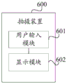
Fig. 5 is a schematic diagram of a possible structure of a camera according to an embodiment of the present disclosure, and as shown in fig. 5, a camera 600 includes: a user input module 601 and a display module 602, wherein:
the user input module 601 is configured to receive a first input that a user moves the electronic device in a direction indicated by a target identifier under the condition that a first shooting preview interface of the first camera is displayed, where the target identifier is a target identifier corresponding to a first shooting object; the user display is used for responding to the first input received by the user input module 601, and displaying a second shooting preview interface of the second camera when the first shooting object is positioned in the shooting range of the second camera; the shooting range of the first camera is different from that of the second camera, and the shooting range of the second camera is smaller than that of the first camera; the second shooting preview interface comprises a first shooting object.
Optionally, the user input module 601 is further configured to receive a second input that the user selects N second subjects from the plurality of subjects displayed on the first shooting preview interface, where the N second subjects are at least one of the plurality of subjects, and N is a positive integer; the user display is also used for responding to the second input and displaying the target identification corresponding to each second shooting object; and the first shooting object is one of the N second shooting objects.
Optionally, the target identifier is further configured to indicate target distance information, where the target distance information is distance information of a shooting range of the first shooting object and the second camera; the user input module 601 is specifically configured to receive a first input of the user moving the electronic device according to the target direction and the distance indicated by the target distance information.
Optionally, the display module 602 is specifically configured to display a second shooting preview interface of the second camera when the target distance information indicates that the first shooting object is a second shooting object closest to the shooting range of the second camera in the N second shooting objects.
Optionally, the display module 602 is further configured to display a target identifier corresponding to a third shooting object when the third shooting object is not included in the second shooting preview interface; the third shooting object is a second shooting object which is positioned outside the shooting range of the second camera in the N second shooting objects.
The shooting device in the embodiment of the present application may be a device, or may be a component, an integrated circuit, or a chip in a terminal. The device can be mobile electronic equipment or non-mobile electronic equipment. By way of example, the mobile electronic device may be a mobile phone, a tablet computer, a notebook computer, a palm top computer, a vehicle-mounted electronic device, a wearable device, an ultra-mobile personal computer (UMPC), a netbook or a Personal Digital Assistant (PDA), and the like, and the non-mobile electronic device may be a server, a Network Attached Storage (NAS), a Personal Computer (PC), a Television (TV), a teller machine or a self-service machine, and the like, and the embodiments of the present application are not particularly limited.
The photographing apparatus in the embodiment of the present application may be an apparatus having an operating system. The operating system may be an Android operating system (Android), an iOS operating system, or other possible operating systems, which is not specifically limited in the embodiments of the present application.
The shooting device provided in the embodiment of the present application can implement each process implemented by the shooting device in the method embodiments of fig. 1 to fig. 4, and is not described here again to avoid repetition.
The beneficial effects of the various implementation manners in this embodiment may specifically refer to the beneficial effects of the corresponding implementation manners in the above method embodiments, and are not described herein again to avoid repetition.
According to the shooting device provided by the embodiment of the application, after a user determines a shooting object, the electronic equipment displays the identification of the first shooting object in the shooting preview interface of the first camera, the user can adjust the shooting angle and area of the electronic equipment according to the identification, and the electronic equipment automatically switches to the shooting preview interface of the telephoto camera under the condition that the first shooting object is located in the shooting range of the second camera, so that the situation that the user cannot find the shooting object after switching to the shooting preview interface of the telephoto camera in the related technology is avoided.
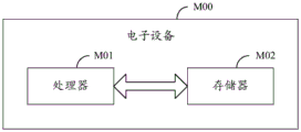
Optionally, as shown in fig. 6, an electronic device M00 is further provided in an embodiment of the present application, and includes a processor M01, a memory M02, and a program or an instruction stored in the memory M02 and executable on the processor M01, where the program or the instruction when executed by the processor M01 implements the processes of the foregoing shooting method embodiment, and can achieve the same technical effects, and details are not repeated here to avoid repetition.
It should be noted that the electronic devices in the embodiments of the present application include the mobile electronic devices and the non-mobile electronic devices described above.
Fig. 7 is a schematic diagram of a hardware structure of an electronic device implementing various embodiments of the present application.
The electronic device 100 includes, but is not limited to: a radio frequency unit 101, a network module 102, an audio output unit 103, an input unit 104, a sensor 105, a display unit 106, a user input unit 107, an interface unit 108, a memory 109, and a processor 110.
Those skilled in the art will appreciate that the electronic device 100 may further comprise a power source (e.g., a battery) for supplying power to various components, and the power source may be logically connected to the processor 110 through a power management system, so as to implement functions of managing charging, discharging, and power consumption through the power management system. The electronic device structure shown in fig. 7 does not constitute a limitation of the electronic device, and the electronic device may include more or less components than those shown, or combine some components, or arrange different components, and thus, the description is omitted here.
The user input unit 107 is configured to receive a first input that a user moves the electronic device in a direction indicated by a target identifier, where the target identifier is a target identifier corresponding to a first shooting object, in a case where a first shooting preview interface of the first camera is displayed; a user display for displaying a second photographing preview interface of the second camera when the first photographing object is located within a photographing range of the second camera in response to the first input received by the user input unit 107; the shooting range of the first camera is different from that of the second camera, and the shooting range of the second camera is smaller than that of the first camera; the second shooting preview interface comprises a first shooting object.
Therefore, when a user opens a shooting interface, after a first shooting object at a far distance to be shot is determined, the electronic equipment can display a target identification corresponding to the first shooting object in a shooting preview interface, then the user can move the electronic equipment according to the direction indicated by the target identification, and under the condition that the first shooting object enters the shooting range of the second camera, the shooting preview interface of the second camera is displayed, so that the electronic equipment can guide the user to move the electronic equipment when the user determines the shooting object, and automatically switch to a long-range shooting interface under the condition that shooting conditions are met, and operation steps of the user when the user uses the electronic equipment to shoot long-range images are reduced.
Optionally, the user input unit 107 is further configured to receive a second input that the user selects N second subjects from the plurality of subjects displayed on the first photographing preview interface, where the N second subjects are at least one of the plurality of subjects, and N is a positive integer; the user display is also used for responding to the second input and displaying the target identification corresponding to each second shooting object; and the first shooting object is one of the N second shooting objects.
Therefore, after the user selects the shot object to be shot, the user can move according to the direction indicated by the target identifier corresponding to each shot object, so that the shot object to be shot enters the shooting range of the second camera, the electronic equipment is triggered to display the shooting preview interface of the second camera, and the user can conveniently shoot the shot object in a long-range view.
Optionally, the target identifier is further configured to indicate target distance information, where the target distance information is distance information of a shooting range of the first shooting object and the second camera; the user input unit 107 is specifically configured to receive a first input that the user moves the electronic device according to the target direction and the distance indicated by the target distance information.
Therefore, the user can move the electronic equipment based on the distance information indicated by the target identification, and the problem of overlarge moving amplitude is prevented.
Optionally, the display unit 106 is specifically configured to display a second shooting preview interface of the second camera if the target distance information indicates that the first shooting object is a second shooting object closest to the shooting range of the second camera in the N second shooting objects.
Therefore, when the user wants to shoot which shooting object, the electronic equipment is moved according to the direction indicated by the target mark corresponding to the shooting object, and when the shooting object enters the shooting range of the second camera, the electronic equipment is triggered to display a second shooting preview interface containing the shooting object.
Optionally, the display unit 106 is further configured to display a target identifier corresponding to the third photographic subject when the third photographic subject is not included in the second shooting preview interface; the third shooting object is a second shooting object which is positioned outside the shooting range of the second camera in the N second shooting objects.
In this way, when the shooting device displays the shooting preview interface of the telephoto camera, the electronic device can be moved based on the direction indicated by the target identifier corresponding to other shooting objects which are not in the shooting preview interface, and the electronic device does not need to be switched back and forth between the two shooting preview interfaces after shooting the long-range image of one shooting object, so that the operation steps are reduced.
According to the electronic equipment provided by the embodiment of the application, after a user determines a shooting object, the electronic equipment displays the identification of the first shooting object in the shooting preview interface of the first camera, the user can adjust the shooting angle and area of the electronic equipment according to the identification, and the electronic equipment automatically switches to the shooting preview interface of the telephoto camera under the condition that the first shooting object is located in the shooting range of the second camera, so that the situation that the user cannot find the shooting object after switching to the shooting preview interface of the telephoto camera in the related technology is avoided.
It should be understood that, in the embodiment of the present application, the input Unit 104 may include a Graphics Processing Unit (GPU) 1041 and a microphone 1042, and the Graphics Processing Unit 1041 processes image data of a still picture or a video obtained by an image capturing device (such as a camera) in a video capturing mode or an image capturing mode. The display unit 106 may include a display panel 1061, and the display panel 1061 may be configured in the form of a liquid crystal display, an organic light emitting diode, or the like. The user input unit 107 includes a touch panel 1071 and other input devices 1072. The touch panel 1071 is also referred to as a touch screen. The touch panel 1071 may include two parts of a touch detection device and a touch controller. Other input devices 1072 may include, but are not limited to, a physical keyboard, function keys (e.g., volume control keys, switch keys, etc.), a trackball, a mouse, and a joystick, which are not described in detail herein. The memory 109 may be used to store software programs as well as various data including, but not limited to, application programs and an operating system. The processor 110 may integrate an application processor, which primarily handles operating systems, user interfaces, applications, etc., and a modem processor, which primarily handles wireless communications. It will be appreciated that the modem processor described above may not be integrated into the processor 110.
The embodiment of the present application further provides a readable storage medium, where a program or an instruction is stored on the readable storage medium, and when the program or the instruction is executed by a processor, the program or the instruction implements each process of the above shooting method embodiment, and can achieve the same technical effect, and in order to avoid repetition, details are not repeated here.
The processor is the processor in the electronic device described in the above embodiment. The readable storage medium includes a computer readable storage medium, such as a Read-Only Memory (ROM), a Random Access Memory (RAM), a magnetic disk or an optical disk, and so on.
The embodiment of the present application further provides a chip, where the chip includes a processor and a communication interface, the communication interface is coupled to the processor, and the processor is configured to run a program or an instruction to implement each process of the above shooting method embodiment, and can achieve the same technical effect, and the details are not repeated here to avoid repetition.
It should be understood that the chips mentioned in the embodiments of the present application may also be referred to as system-on-chip, system-on-chip or system-on-chip, etc.
It should be noted that, in this document, the terms "comprises," "comprising," or any other variation thereof, are intended to cover a non-exclusive inclusion, such that a process, method, article, or apparatus that comprises a list of elements does not include only those elements but may include other elements not expressly listed or inherent to such process, method, article, or apparatus. Without further limitation, an element defined by the phrase "comprising an … …" does not exclude the presence of other like elements in a process, method, article, or apparatus that comprises the element. Further, it should be noted that the scope of the methods and apparatus of the embodiments of the present application is not limited to performing the functions in the order illustrated or discussed, but may include performing the functions in a substantially simultaneous manner or in a reverse order based on the functions involved, e.g., the methods described may be performed in an order different than that described, and various steps may be added, omitted, or combined. In addition, features described with reference to certain examples may be combined in other examples.
Through the above description of the embodiments, those skilled in the art will clearly understand that the method of the above embodiments can be implemented by software plus a necessary general hardware platform, and certainly can also be implemented by hardware, but in many cases, the former is a better implementation manner. Based on such understanding, the technical solutions of the present application may be embodied in the form of a computer software product, which is stored in a storage medium (e.g., ROM/RAM, magnetic disk, optical disk) and includes instructions for enabling an electronic device (e.g., a mobile phone, a computer, a server, or a network device) to execute the method according to the embodiments of the present application.
While the present embodiments have been described with reference to the accompanying drawings, it is to be understood that the invention is not limited to the precise embodiments described above, which are meant to be illustrative and not restrictive, and that various changes may be made therein by those skilled in the art without departing from the spirit and scope of the invention as defined by the appended claims.
Claims (10)
1. A shooting method is applied to electronic equipment, and is characterized by comprising the following steps:
under the condition that a first shooting preview interface of a first camera is displayed, receiving first input, wherein the first input is used for moving the electronic equipment according to the direction indicated by a target identifier, and the target identifier is a target identifier corresponding to a first shooting object;
responding to the first input, and displaying a second shooting preview interface of a second camera when the first shooting object is located in a shooting range of the second camera;
the shooting range of the first camera is different from that of the second camera, and the shooting range of the second camera is smaller than that of the first camera; the first shooting object is displayed in the second shooting preview interface.
2. The method of claim 1, wherein prior to receiving the first input from the user moving the electronic device in the target direction, the method further comprises:
receiving a second input for selecting N second photographic subjects from among the plurality of photographic subjects displayed by the first photographic preview interface, the N second photographic subjects being at least one of the plurality of photographic subjects, N being a positive integer;
responding to the second input, and displaying a target identification corresponding to each second shooting object;
and one second shooting object corresponds to one target identifier, and the first shooting object is one of the N second shooting objects.
3. The method according to claim 2, wherein the target identifier is further used for indicating target distance information, and the target distance information is distance information between the first photographic subject and the photographic range of the second camera;
the receiving a first input, comprising:
and receiving a first input of moving the electronic equipment by a user according to the target direction and the distance indicated by the target distance information.
4. The method of claim 3, wherein the displaying, in response to the first input, a second capture preview interface of a second camera when a first capture object is within a capture range of the second camera comprises:
and displaying a second shooting preview interface of the second camera when the target distance information indicates that the first shooting object is a second shooting object which is closest to the shooting range of the second camera in the N second shooting objects.
5. The method of any of claims 2-4, wherein after displaying the second capture preview interface of the second camera, the method further comprises:
under the condition that a third shooting object is not included in the second shooting preview interface, displaying a target identification corresponding to the third shooting object;
the third shooting object is a second shooting object which is positioned outside the shooting range of the second camera in the N second shooting objects.
6. A camera, characterized in that the camera comprises: the device comprises a user input module and a display module;
the user input module is used for receiving first input under the condition that a first shooting preview interface of a first camera is displayed, wherein the first input is used for moving the electronic equipment according to the direction indicated by a target identifier, and the target identifier is a target identifier corresponding to a first shooting object;
the user display is used for responding to a first input received by the user input module and displaying a second shooting preview interface of a second camera when the first shooting object is positioned in a shooting range of the second camera;
the shooting range of the first camera is different from that of the second camera, and the shooting range of the second camera is smaller than that of the first camera; the first shooting object is displayed in the second shooting preview interface.
7. The apparatus of claim 6,
the user input module is further configured to receive a second input, where the second input is used to select N second photographic subjects from the plurality of photographic subjects displayed on the first photographic preview interface, where the N second photographic subjects are at least one of the plurality of photographic subjects, and N is a positive integer;
the user display is further used for responding to the second input and displaying a target mark corresponding to each second shooting object;
and one second shooting object corresponds to one target identifier, and the first shooting object is one of the N second shooting objects.
8. The apparatus according to claim 7, wherein the target identifier is further configured to indicate target distance information, and the target distance information is distance information between the first photographic subject and a photographic range of the second camera;
the user input module is specifically configured to receive a first input that a user moves the electronic device according to a target direction and a distance indicated by the target distance information.
9. The apparatus of claim 8,
the display module is specifically configured to display a second shooting preview interface of the second camera when the target distance information indicates that the first shooting object is a second shooting object closest to the shooting range of the second camera in the N second shooting objects.
10. The apparatus according to any one of claims 7 to 9,
the display module is further configured to display a target identifier corresponding to a third shooting object when the second shooting preview interface does not include the third shooting object;
the third shooting object is a second shooting object which is positioned outside the shooting range of the second camera in the N second shooting objects.
Priority Applications (1)
| Application Number | Priority Date | Filing Date | Title |
|---|---|---|---|
| CN202110705502.4A CN113473007B (en) | 2021-06-24 | 2021-06-24 | Shooting method and device |
Applications Claiming Priority (1)
| Application Number | Priority Date | Filing Date | Title |
|---|---|---|---|
| CN202110705502.4A CN113473007B (en) | 2021-06-24 | 2021-06-24 | Shooting method and device |
Publications (2)
| Publication Number | Publication Date |
|---|---|
| CN113473007A true CN113473007A (en) | 2021-10-01 |
| CN113473007B CN113473007B (en) | 2023-04-18 |
Family
ID=77872661
Family Applications (1)
| Application Number | Title | Priority Date | Filing Date |
|---|---|---|---|
| CN202110705502.4A Active CN113473007B (en) | 2021-06-24 | 2021-06-24 | Shooting method and device |
Country Status (1)
| Country | Link |
|---|---|
| CN (1) | CN113473007B (en) |
Cited By (3)
| Publication number | Priority date | Publication date | Assignee | Title |
|---|---|---|---|---|
| CN114422692A (en) * | 2022-01-12 | 2022-04-29 | 西安维沃软件技术有限公司 | Video recording method and device and electronic equipment |
| WO2023093274A1 (en) * | 2021-11-29 | 2023-06-01 | 中兴通讯股份有限公司 | Photographing preview method, image fusion method, electronic device, and storage medium |
| WO2023231698A1 (en) * | 2022-05-30 | 2023-12-07 | 荣耀终端有限公司 | Photographing method and related device |
Citations (8)
| Publication number | Priority date | Publication date | Assignee | Title |
|---|---|---|---|---|
| CN103997598A (en) * | 2013-02-14 | 2014-08-20 | 三星电子株式会社 | Method of tracking object using camera and camera system for object tracking |
| US20140347541A1 (en) * | 2013-05-22 | 2014-11-27 | Panasonic Corporation | Imaging apparatus and method of displaying captured image |
| CN108632413A (en) * | 2018-05-15 | 2018-10-09 | 维沃移动通信有限公司 | A kind of photographic method and mobile terminal |
| CN109729266A (en) * | 2018-12-25 | 2019-05-07 | 努比亚技术有限公司 | A kind of image capturing method, terminal and computer readable storage medium |
| CN110445978A (en) * | 2019-06-24 | 2019-11-12 | 华为技术有限公司 | A kind of image pickup method and equipment |
| CN111242988A (en) * | 2020-01-14 | 2020-06-05 | 青岛联合创智科技有限公司 | Method for tracking target by using double pan-tilt coupled by wide-angle camera and long-focus camera |
| WO2021104197A1 (en) * | 2019-11-25 | 2021-06-03 | 维沃移动通信有限公司 | Object tracking method and electronic device |
| CN112954220A (en) * | 2021-03-03 | 2021-06-11 | 北京蜂巢世纪科技有限公司 | Image preview method and device, electronic equipment and storage medium |
-
2021
- 2021-06-24 CN CN202110705502.4A patent/CN113473007B/en active Active
Patent Citations (8)
| Publication number | Priority date | Publication date | Assignee | Title |
|---|---|---|---|---|
| CN103997598A (en) * | 2013-02-14 | 2014-08-20 | 三星电子株式会社 | Method of tracking object using camera and camera system for object tracking |
| US20140347541A1 (en) * | 2013-05-22 | 2014-11-27 | Panasonic Corporation | Imaging apparatus and method of displaying captured image |
| CN108632413A (en) * | 2018-05-15 | 2018-10-09 | 维沃移动通信有限公司 | A kind of photographic method and mobile terminal |
| CN109729266A (en) * | 2018-12-25 | 2019-05-07 | 努比亚技术有限公司 | A kind of image capturing method, terminal and computer readable storage medium |
| CN110445978A (en) * | 2019-06-24 | 2019-11-12 | 华为技术有限公司 | A kind of image pickup method and equipment |
| WO2021104197A1 (en) * | 2019-11-25 | 2021-06-03 | 维沃移动通信有限公司 | Object tracking method and electronic device |
| CN111242988A (en) * | 2020-01-14 | 2020-06-05 | 青岛联合创智科技有限公司 | Method for tracking target by using double pan-tilt coupled by wide-angle camera and long-focus camera |
| CN112954220A (en) * | 2021-03-03 | 2021-06-11 | 北京蜂巢世纪科技有限公司 | Image preview method and device, electronic equipment and storage medium |
Non-Patent Citations (1)
| Title |
|---|
| 徐韬祜等: "基于星图模拟的星空目标提取", 《激光与红外》 * |
Cited By (4)
| Publication number | Priority date | Publication date | Assignee | Title |
|---|---|---|---|---|
| WO2023093274A1 (en) * | 2021-11-29 | 2023-06-01 | 中兴通讯股份有限公司 | Photographing preview method, image fusion method, electronic device, and storage medium |
| CN114422692A (en) * | 2022-01-12 | 2022-04-29 | 西安维沃软件技术有限公司 | Video recording method and device and electronic equipment |
| CN114422692B (en) * | 2022-01-12 | 2023-12-08 | 西安维沃软件技术有限公司 | Video recording method and device and electronic equipment |
| WO2023231698A1 (en) * | 2022-05-30 | 2023-12-07 | 荣耀终端有限公司 | Photographing method and related device |
Also Published As
| Publication number | Publication date |
|---|---|
| CN113473007B (en) | 2023-04-18 |
Similar Documents
| Publication | Publication Date | Title |
|---|---|---|
| CN113473007B (en) | Shooting method and device | |
| CN112135046B (en) | Video shooting method, video shooting device and electronic equipment | |
| CN113093968B (en) | Shooting interface display method and device, electronic equipment and medium | |
| CN111866392B (en) | Shooting prompting method and device, storage medium and electronic equipment | |
| CN112492212B (en) | Photographing method and device, electronic equipment and storage medium | |
| CN112738402B (en) | Shooting method, shooting device, electronic equipment and medium | |
| CN112637500B (en) | Image processing method and device | |
| CN113141450A (en) | Shooting method, shooting device, electronic equipment and medium | |
| CN113473004A (en) | Shooting method and device | |
| CN112291473B (en) | Focusing method and device and electronic equipment | |
| CN112714253A (en) | Video recording method and device, electronic equipment and readable storage medium | |
| CN114125268A (en) | Focusing method and device | |
| CN112929566B (en) | Display control method, display control device, electronic apparatus, and medium | |
| CN113866782A (en) | Image processing method and device and electronic equipment | |
| CN112437232A (en) | Shooting method, shooting device, electronic equipment and readable storage medium | |
| CN112911059A (en) | Photographing method and device, electronic equipment and readable storage medium | |
| CN113286085B (en) | Display control method and device and electronic equipment | |
| CN114173029B (en) | Shooting method and device and electronic equipment | |
| CN112653841B (en) | Shooting method and device and electronic equipment | |
| CN112153291B (en) | Photographing method and electronic equipment | |
| CN112584110B (en) | White balance adjusting method and device, electronic equipment and storage medium | |
| CN114125226A (en) | Image shooting method and device, electronic equipment and readable storage medium | |
| CN113542599A (en) | Image shooting method and device | |
| CN113891018A (en) | Shooting method and device and electronic equipment | |
| CN113794833A (en) | Shooting method and device and electronic equipment |
Legal Events
| Date | Code | Title | Description |
|---|---|---|---|
| PB01 | Publication | ||
| PB01 | Publication | ||
| SE01 | Entry into force of request for substantive examination | ||
| SE01 | Entry into force of request for substantive examination | ||
| GR01 | Patent grant | ||
| GR01 | Patent grant |