CN113464659A - High-parameter stop valve - Google Patents
High-parameter stop valve Download PDFInfo
- Publication number
- CN113464659A CN113464659A CN202110876891.7A CN202110876891A CN113464659A CN 113464659 A CN113464659 A CN 113464659A CN 202110876891 A CN202110876891 A CN 202110876891A CN 113464659 A CN113464659 A CN 113464659A
- Authority
- CN
- China
- Prior art keywords
- valve
- fixedly connected
- clack
- auxiliary
- pipe
- Prior art date
- Legal status (The legal status is an assumption and is not a legal conclusion. Google has not performed a legal analysis and makes no representation as to the accuracy of the status listed.)
- Granted
Links
- 238000004891 communication Methods 0.000 claims abstract description 5
- 230000000903 blocking effect Effects 0.000 claims description 3
- 230000006835 compression Effects 0.000 claims description 3
- 238000007906 compression Methods 0.000 claims description 3
- 238000005192 partition Methods 0.000 claims 2
- XLYOFNOQVPJJNP-UHFFFAOYSA-N water Substances O XLYOFNOQVPJJNP-UHFFFAOYSA-N 0.000 description 16
- 238000004140 cleaning Methods 0.000 description 8
- 239000012535 impurity Substances 0.000 description 7
- 230000000694 effects Effects 0.000 description 6
- 239000007788 liquid Substances 0.000 description 6
- 238000007789 sealing Methods 0.000 description 5
- 230000002457 bidirectional effect Effects 0.000 description 3
- 239000012530 fluid Substances 0.000 description 3
- 238000009434 installation Methods 0.000 description 2
- 238000010030 laminating Methods 0.000 description 2
- 238000012423 maintenance Methods 0.000 description 2
- 230000001105 regulatory effect Effects 0.000 description 2
- 241000521257 Hydrops Species 0.000 description 1
- 206010030113 Oedema Diseases 0.000 description 1
- 238000005299 abrasion Methods 0.000 description 1
- 238000009825 accumulation Methods 0.000 description 1
- 238000010276 construction Methods 0.000 description 1
- 230000002035 prolonged effect Effects 0.000 description 1
- 230000001737 promoting effect Effects 0.000 description 1
Images


Classifications
-
- F—MECHANICAL ENGINEERING; LIGHTING; HEATING; WEAPONS; BLASTING
- F16—ENGINEERING ELEMENTS AND UNITS; GENERAL MEASURES FOR PRODUCING AND MAINTAINING EFFECTIVE FUNCTIONING OF MACHINES OR INSTALLATIONS; THERMAL INSULATION IN GENERAL
- F16K—VALVES; TAPS; COCKS; ACTUATING-FLOATS; DEVICES FOR VENTING OR AERATING
- F16K1/00—Lift valves or globe valves, i.e. cut-off apparatus with closure members having at least a component of their opening and closing motion perpendicular to the closing faces
-
- B—PERFORMING OPERATIONS; TRANSPORTING
- B08—CLEANING
- B08B—CLEANING IN GENERAL; PREVENTION OF FOULING IN GENERAL
- B08B9/00—Cleaning hollow articles by methods or apparatus specially adapted thereto
- B08B9/02—Cleaning pipes or tubes or systems of pipes or tubes
- B08B9/027—Cleaning the internal surfaces; Removal of blockages
- B08B9/032—Cleaning the internal surfaces; Removal of blockages by the mechanical action of a moving fluid, e.g. by flushing
-
- F—MECHANICAL ENGINEERING; LIGHTING; HEATING; WEAPONS; BLASTING
- F16—ENGINEERING ELEMENTS AND UNITS; GENERAL MEASURES FOR PRODUCING AND MAINTAINING EFFECTIVE FUNCTIONING OF MACHINES OR INSTALLATIONS; THERMAL INSULATION IN GENERAL
- F16K—VALVES; TAPS; COCKS; ACTUATING-FLOATS; DEVICES FOR VENTING OR AERATING
- F16K1/00—Lift valves or globe valves, i.e. cut-off apparatus with closure members having at least a component of their opening and closing motion perpendicular to the closing faces
- F16K1/32—Details
-
- F—MECHANICAL ENGINEERING; LIGHTING; HEATING; WEAPONS; BLASTING
- F16—ENGINEERING ELEMENTS AND UNITS; GENERAL MEASURES FOR PRODUCING AND MAINTAINING EFFECTIVE FUNCTIONING OF MACHINES OR INSTALLATIONS; THERMAL INSULATION IN GENERAL
- F16K—VALVES; TAPS; COCKS; ACTUATING-FLOATS; DEVICES FOR VENTING OR AERATING
- F16K15/00—Check valves
- F16K15/02—Check valves with guided rigid valve members
- F16K15/06—Check valves with guided rigid valve members with guided stems
- F16K15/063—Check valves with guided rigid valve members with guided stems the valve being loaded by a spring
-
- F—MECHANICAL ENGINEERING; LIGHTING; HEATING; WEAPONS; BLASTING
- F16—ENGINEERING ELEMENTS AND UNITS; GENERAL MEASURES FOR PRODUCING AND MAINTAINING EFFECTIVE FUNCTIONING OF MACHINES OR INSTALLATIONS; THERMAL INSULATION IN GENERAL
- F16K—VALVES; TAPS; COCKS; ACTUATING-FLOATS; DEVICES FOR VENTING OR AERATING
- F16K15/00—Check valves
- F16K15/18—Check valves with actuating mechanism; Combined check valves and actuated valves
-
- F—MECHANICAL ENGINEERING; LIGHTING; HEATING; WEAPONS; BLASTING
- F16—ENGINEERING ELEMENTS AND UNITS; GENERAL MEASURES FOR PRODUCING AND MAINTAINING EFFECTIVE FUNCTIONING OF MACHINES OR INSTALLATIONS; THERMAL INSULATION IN GENERAL
- F16K—VALVES; TAPS; COCKS; ACTUATING-FLOATS; DEVICES FOR VENTING OR AERATING
- F16K27/00—Construction of housing; Use of materials therefor
- F16K27/02—Construction of housing; Use of materials therefor of lift valves
-
- F—MECHANICAL ENGINEERING; LIGHTING; HEATING; WEAPONS; BLASTING
- F16—ENGINEERING ELEMENTS AND UNITS; GENERAL MEASURES FOR PRODUCING AND MAINTAINING EFFECTIVE FUNCTIONING OF MACHINES OR INSTALLATIONS; THERMAL INSULATION IN GENERAL
- F16K—VALVES; TAPS; COCKS; ACTUATING-FLOATS; DEVICES FOR VENTING OR AERATING
- F16K3/00—Gate valves or sliding valves, i.e. cut-off apparatus with closing members having a sliding movement along the seat for opening and closing
- F16K3/02—Gate valves or sliding valves, i.e. cut-off apparatus with closing members having a sliding movement along the seat for opening and closing with flat sealing faces; Packings therefor
- F16K3/0281—Guillotine or blade-type valves, e.g. no passage through the valve member
Landscapes
- Engineering & Computer Science (AREA)
- General Engineering & Computer Science (AREA)
- Mechanical Engineering (AREA)
- Lift Valve (AREA)
Abstract
The invention relates to the field of valves, in particular to a high-parameter stop valve. A high-parameter stop valve comprises a valve body, a separating body, a middle through hole, a communication hole, an outer valve pipe, an inner valve pipe, a valve cover, a valve rod I, a two-way valve clack, an auxiliary pipe and an auxiliary cover, wherein the separating body is arranged inside the valve body and divides the valve body into a left passage and a right passage; wherein, well opening and interior valve pipe one of the two all can be opened and closed through two-way valve clack and two-way valve clack can open well opening and interior valve pipe simultaneously, can be convenient for maintain inside the valve body.
Description
Technical Field
The invention relates to the field of valves, in particular to a high-parameter stop valve.
Background
The valve has a plug-shaped valve flap, and its sealing surface can be divided into plane and conical surface, and the valve flap can make linear movement along the central line of fluid. The medium flow direction of the stop valve is changed into that the medium enters the valve cavity from the upper part of the valve clack, and at this time, the force for closing the valve is reduced and the force for opening the valve is increased under the action of medium pressure, the opening and closing time of the valve rod is relatively short, once the stop valve is in an opening state, the sealing surface of the valve seat and the sealing surface of the valve clack are not in any contact, and the sealing surface of the stop valve is less in mechanical abrasion, so that the stop valve has a very reliable cutting-off effect. The effect of stop valve is actually only opened entirely and closed entirely under general condition, just carries out a effect of cutting off promptly, and the stop valve has three port, is left port, right port and last port respectively, and the port is used for connecting on the pipeline about, and the last port is then the valve gap valve rod, and it can the hydrops to have the cavity dead angle inside it, and inside four corners is easily piled up the dirt and is difficult to be cleared up.
Disclosure of Invention
The invention provides a high-parameter stop valve, aiming at facilitating the maintenance of the interior of a valve body.
The above purpose is realized by the following technical scheme:
a high-parameter stop valve comprises a valve body, a separating body, a middle through hole, a communication hole, an outer valve pipe, an inner valve pipe, a valve cover, a valve rod I, a two-way valve clack, an auxiliary pipe and an auxiliary cover, wherein the separating body is arranged inside the valve body and divides the valve body into a left passage and a right passage; wherein, well through-port and interior valve pipe one of the two can both be opened and closed through two-way valve clack and two-way valve clack can open well through-port and interior valve pipe simultaneously.
Drawings
FIG. 1 illustrates a unitary construction;
FIG. 2 illustrates the overall internal structure in plan view;
FIG. 3 illustrates the overall internal structure in perspective view;
FIG. 4 illustrates the valve body relative structure;
FIG. 5 illustrates an outer valve tube related structure;
FIG. 6 illustrates a bi-directional flap;
FIG. 7 illustrates a valve collar;
FIG. 8 illustrates an auxiliary flap;
FIG. 9 illustrates an adjustment member;
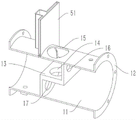
FIG. 10 illustrates a related structure of a plate housing;
fig. 11 illustrates the structure of the valve plate.
Detailed Description
Referring to fig. 4, the valve body 11 is a circular tube structure, the left end and the right end of the valve body are connected, one of the left end and the right end of the valve body 11 can be used as a water inlet or a water outlet, and the two ends of the valve body 11 can be used as a water inlet or a water outlet. Referring to fig. 2 to 4, when the valve stem i 24 is rotated, the valve stem i 24 can move the two-way flap 25 up and down. When the valve rod I24 drives the two-way valve clack 25 to move downwards and the two-way valve clack 25 is located between the middle through opening 14 and the inner valve pipe 22, the auxiliary pipe 26 is a water inlet, and the two ends of the valve body 11 are water outlets. When the bidirectional valve clack 25 further descends to block the middle through hole 14, one condition is that the auxiliary cover 27 is opened, the auxiliary pipe 26 is used for water inlet, and the left end of the bidirectional valve clack 25 is used for water outlet; the second, the auxiliary lid 27 is closed, and the whole stop valve is closed. When the two-way valve clack 25 moves upwards to block the inner valve pipe 22, the left end of the valve body 11 can be a water inlet part, and the right end is a water outlet part; similarly, the right end of the valve body 11 can be a water inlet, and the left end can be a water outlet. Further, the inner valve pipe 22 is sealed by the two-way valve clack 25, the auxiliary cover 27 is opened, the pipeline cleaning liquid is added into the auxiliary pipe 26, after the pipeline cleaning liquid is placed for a period of time, the cleaning is realized in the outer valve pipe 21 and the auxiliary pipe 26, and then the cleaning liquid can be discharged to clean the valve body 11 part so as to improve index parameters inside the stop valve.
The two ends of the valve body 11 are both provided with flanges 12 for convenient connection, the separating body 13 is of a ladder structure, the vertical section I, the horizontal section and the vertical section II are respectively arranged from left to right, and the lower end of the inner valve pipe 22 is arranged above the horizontal section close to the separating body 13 so as to reduce the movement stroke of the two-way valve clack 25. The upper and lower both ends of two-way valve clack 25 have the chamfer face, and the chamfer face that is located the top is used for closely laminating with the lower extreme of interior valve pipe 22, and the chamfer face that is located the below is used for closely laminating with well opening 14 department on the horizontal segment for sealed effect obtains promoting, and outer valve pipe 21 is preferably dismantled with valve body 11 and is connected, and then is convenient for change or maintain two-way valve clack 25. The separating body 13 with the ladder structure enables dirt and impurities in the valve body 11 to be deposited and concentrated near the separating body 13, and further enables cleaning liquid to directly impact the separating body 13 through the auxiliary pipe 26 for cleaning, and therefore maintenance is convenient.
Referring to fig. 2, 4 and 8, the separating body 13 is further provided with an upper through opening 16 and a lower through opening 17, wherein the upper through opening 16 is provided on the vertical section i and the lower through opening 17 is provided on the vertical section ii. Furthermore, the stop valve also comprises two auxiliary valve flaps which are matched with the upper through opening 16 and the lower through opening 17. The auxiliary valve clack comprises a support seat 31, a square column 32, a one-way valve clack 33 and a compression spring 34, the support seat 31 is connected with the square column 32 in a sliding mode, the right end of the square column 32 is fixedly connected with the one-way valve clack 33, the compression spring 34 is sleeved on the square column 32 and located between the support seat 31 and the one-way valve clack 33, one of the auxiliary valve clacks is arranged on the left side of the vertical section I, the right end of the one-way valve clack 33 is attached to the left end face of the vertical section I to block the lower through hole 17, at the moment, when the middle through hole 14 is closed, water cannot flow from the left end to the right end of the valve body 11, only the water can pass through the lower through hole 17 from right to left, the one-way valve clack 33 cannot be flushed when the flow is low from right to left, when the water pressure is high, and when the two-way valve clack 25 is fully opened and is not enough to release the pressure, water can pass through the one-way valve clack 33 to open the direction, so that the flow is further improved.
In a similar way, the other auxiliary valve clack is arranged on the right side of the vertical section II, the one-way valve clack 33 included by the auxiliary valve clack is attached to the right end face of the vertical section II to block the upper through hole 16, the flow from right to left in the valve body 11 can be further improved, and the problem that the flow is small due to the fact that the inner through hole of the conventional stop valve is small is solved. Furthermore, when the flow rate is small, dirt and impurities are easy to accumulate near the passage of the stop valve, the one-way valve clack 33 in the corresponding direction is flushed away by increasing the flow rate, and the dirt and impurities near the one-way valve clack 33 can be quickly flushed away, so that the blocking phenomenon is avoided. For example, small flow from right to left in the valve body 11 is easy to accumulate impurities on the right of the vertical section i, and the flow from right to left is increased to open the lower through opening 17, so that the impurities accumulated on the right of the vertical section i can be cleaned; from left to right the miniflow easily accumulates impurity in I left of vertical section, increases the one-way valve clack 33 of opening 16 in the flow reopening from a left side to the right this moment, can clear up I left accumulation impurity of vertical section, and this is that the terminal surface is opened the pressure release and is discharged the realization after utilizing rivers to strike vertical section I first then the passageway, so can improve cleaning efficiency and effect repeatedly. Further, referring to fig. 7 with reference to fig. 2 or 3, the valve further includes two valve rings 18 installed at the upper through opening 16 and the lower through opening 17, the valve rings 18 are used for replacing the separating bodies 13 to contact the corresponding check valve flaps 33, so that the service life is prolonged, only the valve rings 18 need to be replaced, and the valve rings 18 are provided with chamfered surfaces used in cooperation with the check valve flaps 33, so that the attaching and sealing capabilities are improved.
Further, referring to fig. 9, the stop valve further includes an adjusting member, the adjusting member includes a valve rod ii 41 and a supporting portion 42, the supporting portion 42 is fixedly connected to the upper end of the valve rod ii 41, the valve rod ii 41 is in threaded connection with the valve body 11, and two adjusting members are provided.
Referring to fig. 2 or 3, two adjustment members are used with two auxiliary flaps, respectively. Example adjustment elements on the left side: one of the valve rods II 41 is located at the left end of the left side square column 32, the valve rod II 41 is used for lifting the supporting part 42 to block the square column 32, so that the left side check valve clack 33 is locked, but the supporting part 42 cannot be adjusted under the conditions that the left side square column 32 is already displaced and the check valve clack 33 is already opened by the simple block-shaped structure, and the supporting part 42 can be clamped below the square column 32 after being lifted. The further abutting portion 42 is of a frustum structure, in a general case, the abutting portion 42 is not lifted, the diameter of the abutting portion 42 is increased from top to bottom, the square column 32 can move leftward until abutting against the abutting portion 42, and when the abutting portion 42 is lifted, the amount of leftward movement of the square column 32 is gradually reduced to reduce the maximum value of the right-to-left flow until the square column 32 cannot move leftward and is completely locked by the abutting portion 42. The principle and the effect that the regulating part that is located the right side set up are the same with the regulating part that is located the left side, and then in order to reduce the maximum value from left to right flow, or directly lock and die for use is nimble. Furthermore, the free end of the square column 32 is provided with an arc portion 35, which is convenient for reducing the friction force with the corresponding abutting portion 42.
The stop valve further comprises a plate shell 51, a valve plate 52, a shell cover 53 and a valve rod III 54, wherein the plate shell 51 is fixedly connected and communicated with the upper end of the valve body 11, the valve plate 52 is connected in the plate shell 51 in a sliding manner, the shell cover 53 is detachably and fixedly connected with the upper end of the valve plate 52, the valve rod III 54 is in threaded connection with the shell cover 53, the lower end of the valve rod III 54 is rotatably connected with the upper end of the valve plate 52, the valve plate 52 can be driven to lift by rotating the valve rod III 54, the valve plate 52 is lowered to be attached to the left end of a horizontal section to block a passage at the left part of the valve body 11, and when the middle through hole 14 is blocked by the bidirectional valve clack 25, liquid can enter from the auxiliary pipe 26 and is only discharged from the upper through hole 16 to clean the right passage; when the valve plate 52 is lifted, the left passage is opened, and the middle through hole 14 is closed, the left passage can be cleaned;
it is also possible to let the cleaning liquid rest above the horizontal section and only open the two-way flap 25 to wash the horizontal section heavily. Namely, the left, the middle, the right and the corners inside the stop valve can be cleaned intensively. When the stop valve is designed, the stop valve has directionality, that is, fluid passes through the stop valve body, and therefore, the stop valve needs to be installed according to the flowing direction of the fluid in the pipeline when the stop valve is installed, and if the design direction of the stop valve body is opposite to the flowing direction in the pipeline after the stop valve is installed, the usability of the stop valve is affected. The stop valve does not need to consider the installation direction or the problem of reversing after installation, and all the passages can be flexibly opened and closed.
Claims (10)
1. A high-parameter stop valve comprises a valve body (11) and a separating body (13) which is arranged in the valve body (11) and divides the valve body (11) into a left passage and a right passage, and a middle through opening (14) provided in the partition body (13) and communicating the two passages, and a communication port (15) which is arranged at the upper part of the valve body (11) and is coaxial with the middle through port (14), and an outer valve pipe (21) which is fixedly connected with the upper part of the valve body (11) and communicated with the communication port (15), and an inner valve tube (22) integrally connected to the inner lower end of the outer valve tube (21), a valve cover (23) which is detachably connected with the upper end of the outer valve pipe (21), and a valve rod I (24) which is in threaded connection with the valve cover (23), a two-way valve clack (25) fixedly connected to the lower end of the valve rod I (24), an auxiliary pipe (26) fixedly connected and communicated with the upper side of the outer valve pipe (21), and an auxiliary cover (27) detachably and fixedly connected to the upper end of the auxiliary pipe (26); wherein one of the middle through opening (14) and the inner valve tube (22) can be opened and closed by the two-way valve flap (25) and the two-way valve flap (25) can simultaneously open the middle through opening (14) and the inner valve tube (22).
2. The shut-off valve of claim 1, wherein the inner valve tube (22) passes through the communication port (15) and is disposed proximate the central through port (14).
3. A stop valve according to claim 2 or 1, wherein the valve body (11) is provided with flanges (12) at both left and right ends.
4. A stop valve according to claim 3, wherein the partition (13) is a stepped structure consisting of a vertical section i, a horizontal section and a vertical section ii, respectively, from left to right.
5. A stop valve as claimed in claim 4, further comprising an upper port (16) provided in the vertical section II, and a lower port (17) provided in the vertical section I, and an auxiliary flap; the auxiliary valve clack comprises a support seat (31), a square column (32) connected to the support seat (31) in a sliding manner, a one-way valve clack (33) fixedly connected to the right end of the square column (32), and a compression spring (34) sleeved on the square column (32) and positioned between the square column (32) and the support seat (31); the auxiliary valve clacks are two, one check valve clack (33) is attached to the left end of the vertical section I and used for blocking the lower through hole (17) in a one-way mode, the other check valve clack (33) is attached to the right end of the vertical section II and used for blocking the upper through hole (16), and the abutting seat (31) is fixedly connected with the inner end of the valve body (11).
6. The stop valve of claim 5, further comprising valve rings (18) fixedly connected in the upper through opening (16) and the lower through opening (17), and the two check valve flaps (33) are respectively attached to the two valve rings (18).
7. The stop valve of claim 6, further comprising an adjusting member, wherein the adjusting member comprises a valve rod II (41) and an abutting part (42) fixedly connected to the valve rod II (41); the adjusting part is equipped with two, and two valve rods II (41) all with valve body (11) threaded connection, two portions of supporting (42) can support respectively at the free end department of two square columns (32).
8. The stop valve of claim 7, wherein the abutting portion (42) is of a frustum structure, and the side of the abutting portion (42) with the smaller diameter faces the axis of the valve body (11).
9. A stop valve as claimed in claim 8, wherein the free end of the square column (32) is provided with an arc (35).
10. The stop valve of claim 9, further comprising a plate shell (51) fixedly connected to and communicated with the upper end of the valve body (11), a valve plate (52) slidably connected in the plate shell (51), a cover (53) fixedly connected to the upper end of the plate shell (51), and a valve rod III (54) screwed on the plate shell (51), wherein the bottom of the valve rod III (54) is rotatably connected with the upper end of the valve plate (52), and the valve plate (52) can be attached to the horizontal section to form a containing cavity in the space above the horizontal section.
Priority Applications (1)
| Application Number | Priority Date | Filing Date | Title |
|---|---|---|---|
| CN202110876891.7A CN113464659B (en) | 2021-07-31 | 2021-07-31 | High-parameter stop valve |
Applications Claiming Priority (1)
| Application Number | Priority Date | Filing Date | Title |
|---|---|---|---|
| CN202110876891.7A CN113464659B (en) | 2021-07-31 | 2021-07-31 | High-parameter stop valve |
Publications (2)
| Publication Number | Publication Date |
|---|---|
| CN113464659A true CN113464659A (en) | 2021-10-01 |
| CN113464659B CN113464659B (en) | 2023-03-03 |
Family
ID=77883665
Family Applications (1)
| Application Number | Title | Priority Date | Filing Date |
|---|---|---|---|
| CN202110876891.7A Active CN113464659B (en) | 2021-07-31 | 2021-07-31 | High-parameter stop valve |
Country Status (1)
| Country | Link |
|---|---|
| CN (1) | CN113464659B (en) |
Cited By (1)
| Publication number | Priority date | Publication date | Assignee | Title |
|---|---|---|---|---|
| CN114576390A (en) * | 2022-01-29 | 2022-06-03 | 江苏苏盐阀门机械有限公司 | Stop valve |
Citations (7)
| Publication number | Priority date | Publication date | Assignee | Title |
|---|---|---|---|---|
| EP0907046A1 (en) * | 1997-10-02 | 1999-04-07 | Giorgio Scanferla | Improved valve assembly for heating systems and water-heating apparatuses |
| CN201258981Y (en) * | 2008-09-26 | 2009-06-17 | 杭州耐特阀门有限公司 | Valve flap protection cover plate structure for three-way inverting slurry valve |
| CN201593624U (en) * | 2009-10-12 | 2010-09-29 | 天津市圣恺工业技术发展有限公司 | Three-way switching ceramic stop valve |
| CN201810816U (en) * | 2010-09-26 | 2011-04-27 | 福建博大塑业新材料有限公司 | Stop valve of water supply pipeline |
| CN204312768U (en) * | 2014-12-15 | 2015-05-06 | 河南盛誉实业有限公司 | Three-way valve |
| CN105202223A (en) * | 2015-09-17 | 2015-12-30 | 哈电集团哈尔滨电站阀门有限公司 | Hydraulic high-pressure heater three-way valve |
| CN204985842U (en) * | 2015-09-18 | 2016-01-20 | 铜陵天海流体控制股份有限公司 | Two tee bend switching -over stop valves |
-
2021
- 2021-07-31 CN CN202110876891.7A patent/CN113464659B/en active Active
Patent Citations (7)
| Publication number | Priority date | Publication date | Assignee | Title |
|---|---|---|---|---|
| EP0907046A1 (en) * | 1997-10-02 | 1999-04-07 | Giorgio Scanferla | Improved valve assembly for heating systems and water-heating apparatuses |
| CN201258981Y (en) * | 2008-09-26 | 2009-06-17 | 杭州耐特阀门有限公司 | Valve flap protection cover plate structure for three-way inverting slurry valve |
| CN201593624U (en) * | 2009-10-12 | 2010-09-29 | 天津市圣恺工业技术发展有限公司 | Three-way switching ceramic stop valve |
| CN201810816U (en) * | 2010-09-26 | 2011-04-27 | 福建博大塑业新材料有限公司 | Stop valve of water supply pipeline |
| CN204312768U (en) * | 2014-12-15 | 2015-05-06 | 河南盛誉实业有限公司 | Three-way valve |
| CN105202223A (en) * | 2015-09-17 | 2015-12-30 | 哈电集团哈尔滨电站阀门有限公司 | Hydraulic high-pressure heater three-way valve |
| CN204985842U (en) * | 2015-09-18 | 2016-01-20 | 铜陵天海流体控制股份有限公司 | Two tee bend switching -over stop valves |
Cited By (1)
| Publication number | Priority date | Publication date | Assignee | Title |
|---|---|---|---|---|
| CN114576390A (en) * | 2022-01-29 | 2022-06-03 | 江苏苏盐阀门机械有限公司 | Stop valve |
Also Published As
| Publication number | Publication date |
|---|---|
| CN113464659B (en) | 2023-03-03 |
Similar Documents
| Publication | Publication Date | Title |
|---|---|---|
| US7232107B2 (en) | Control valve having a filter screen mounted flush with a valve closure member surface | |
| US3367621A (en) | Diaphragm operated valve including an adjustable choke passage | |
| CN113464659B (en) | High-parameter stop valve | |
| CN112013126B (en) | Pressure balance type adjusting ball valve | |
| CN220505898U (en) | Check valve convenient to dismantle and overhaul | |
| KR100821655B1 (en) | Complex control valve body for a fluid control valve | |
| US7096880B2 (en) | Float type steam trap | |
| AU2012211932B2 (en) | Valve | |
| CN111963728A (en) | Novel embedded check valve | |
| CN2733117Y (en) | Quick opening mud valve | |
| CN217328616U (en) | Check valve for sewage treatment | |
| CN109838597A (en) | A kind of anti-back pressure spring Fall lift safety valve | |
| CN216895927U (en) | Low-resistance backflow preventer | |
| CN216715326U (en) | K-shaped liquid control valve with no diaphragm, shaft sleeve and spring | |
| CN116357878A (en) | Vertical high-pressure natural gas drain valve | |
| CN217355701U (en) | One-way valve | |
| CN110319266A (en) | Floating ball core pipe valve | |
| CN211975897U (en) | Balanced type cut-off, regulation, filtration and blow-off valve | |
| CN220980478U (en) | Multistage sealing bypass valve | |
| CN210218804U (en) | Flow-guiding damping slow-closing check valve | |
| CN216112198U (en) | Pilot-operated ball valve | |
| CN109307089B (en) | High-frequency quick-opening check valve | |
| CN213117615U (en) | Self-operated balance valve | |
| CN212480249U (en) | Vertical spring check valve | |
| CN209909211U (en) | Regulating valve |
Legal Events
| Date | Code | Title | Description |
|---|---|---|---|
| PB01 | Publication | ||
| PB01 | Publication | ||
| SE01 | Entry into force of request for substantive examination | ||
| SE01 | Entry into force of request for substantive examination | ||
| GR01 | Patent grant | ||
| GR01 | Patent grant | ||
| PE01 | Entry into force of the registration of the contract for pledge of patent right | ||
| PE01 | Entry into force of the registration of the contract for pledge of patent right |
Denomination of invention: A high parameter shut-off valve Granted publication date: 20230303 Pledgee: Agricultural Bank of China Limited Binhai County sub branch Pledgor: JIUTONG GROUP Co.,Ltd. Registration number: Y2024980001143 |