CN1134606C - Illumination system using edge-illuminated hollow waveguide and lenticular optical structures - Google Patents
Illumination system using edge-illuminated hollow waveguide and lenticular optical structures Download PDFInfo
- Publication number
- CN1134606C CN1134606C CNB998131326A CN99813132A CN1134606C CN 1134606 C CN1134606 C CN 1134606C CN B998131326 A CNB998131326 A CN B998131326A CN 99813132 A CN99813132 A CN 99813132A CN 1134606 C CN1134606 C CN 1134606C
- Authority
- CN
- China
- Prior art keywords
- illuminator
- light
- smooth
- angle
- hollow waveguide
- Prior art date
- Legal status (The legal status is an assumption and is not a legal conclusion. Google has not performed a legal analysis and makes no representation as to the accuracy of the status listed.)
- Expired - Fee Related
Links
Images


Classifications
-
- G—PHYSICS
- G02—OPTICS
- G02B—OPTICAL ELEMENTS, SYSTEMS OR APPARATUS
- G02B27/00—Optical systems or apparatus not provided for by any of the groups G02B1/00 - G02B26/00, G02B30/00
-
- G—PHYSICS
- G02—OPTICS
- G02B—OPTICAL ELEMENTS, SYSTEMS OR APPARATUS
- G02B6/00—Light guides; Structural details of arrangements comprising light guides and other optical elements, e.g. couplings
- G02B6/0001—Light guides; Structural details of arrangements comprising light guides and other optical elements, e.g. couplings specially adapted for lighting devices or systems
- G02B6/0096—Light guides; Structural details of arrangements comprising light guides and other optical elements, e.g. couplings specially adapted for lighting devices or systems the lights guides being of the hollow type
-
- Y—GENERAL TAGGING OF NEW TECHNOLOGICAL DEVELOPMENTS; GENERAL TAGGING OF CROSS-SECTIONAL TECHNOLOGIES SPANNING OVER SEVERAL SECTIONS OF THE IPC; TECHNICAL SUBJECTS COVERED BY FORMER USPC CROSS-REFERENCE ART COLLECTIONS [XRACs] AND DIGESTS
- Y10—TECHNICAL SUBJECTS COVERED BY FORMER USPC
- Y10S—TECHNICAL SUBJECTS COVERED BY FORMER USPC CROSS-REFERENCE ART COLLECTIONS [XRACs] AND DIGESTS
- Y10S385/00—Optical waveguides
- Y10S385/901—Illuminating or display apparatus
Abstract
An illumination system(10)having a hollow waveguide(50)including first(70)and second(80)light directing arrays(LDA), each having a plurality of generally lenticular prisms(74,84)defined thereon and arranged generally orthogonally with respect to each other. Light rays from a light source(20)enter the waveguide(50)through a light input side(58)and emerge from the waveguide(50)through a light output side(56)at a predetermined flux and angular distribution. The light output flux and angular distribution can each be independently controlled by the LDAs(70, 80)to provide an illumination system(10) that can be configured for various light output distribution and intensity requirements.
Description
Technical field
The present invention relates to illuminator, relate in particular to the edge light system with hollow waveguide and one or two stacked transmitted light directional array (LDA), this transmitted light directional array provides output light from the illuminator with predetermined angle distribution.
Background technology
Light fixture that uses in working environment or illuminator must be able to be fit to be usually located at the condition of work of the common paper on the horizontal surface below beholder's eyes, can be fit to be usually located at the condition of work of visual display terminal (VDT) of the computer in beholder's eyes the place ahead again, and the condition of work of computer visual display terminal (VDT) comprises the ceiling portion in the visual field.Concerning the condition of work of VUT, importantly control be installed in the light fixture on the ceiling brightness so that reflected glare on the VDT or diffuse reflection minimize.By general experience, the brightness of ceiling should be greater than ten (10) times of VDT screen intensity.For example, see " American National Standard rules: office lighting ", ANSI/IESNA RP-1-1993,34-41 page or leaf.Ceiling light fixture can cause: the image dazzle, and the beholder sees the image that illuminator is arranged on VDT; The area dazzle is presented at the brightness area on the VDT; Evenly dazzle, it reduces the brightness and contrast of VDT.These glare problem all produce adverse influence to the condition of work of VDT.For indirect light fixture, distribution of the light of expansion and the brightness of light output uniformly will help to handle glare problem usually.In addition, export with the light of watching angle control light fixture between 55 ° and 90 °, (for example, the mean flow rate of suggestion when the vertical and horizontal of the 45 of vertical and horizontal are watched relatively, in this angle viewing areas is not more than 850cd/m can further to reduce undesirable dazzle effect
2).Therefore, wish to make a kind of illuminator, it is controlled and more accurately or " clearly " angle of cut-off that this illuminator can provide; This angle of cut-off to exceed illuminator the then essentially no meaning of output light or can be unheeded.
The glare problem brighter, that compacter and more effective light source has aggravated ceiling light fixture of continuous development.If direct viewing, some light source in these emerging light sources can damage people's eyes.In addition, the Ming Liang light eyes that directly enter the people will cause fatigue and reduce operating efficiency.Therefore, need provide especially and have controlled and the illuminator of angle of cut-off clearly.
Illuminator provides a device that the output light of light source is repositioned onto ad-hoc location.For having the light source that the output of narrow angle distributes, people's such as Cobb US 4,984,114 and people's such as Miller US 5,190,370 disclose a kind of hollow illuminator, and this illuminator comprises a plurality of prisms, in prism, from the light of light source before the illuminator outgoing by fully to internal reflection.Light emitted circular cone light beam (US 4,984,114) or collimated light beam (US5,190,370), this light beam is with the low-angle contact prism on the plane of relative illuminator output surface.All light of light emitted all enter prism and penetrate from illuminator.The angle of controlling light source by the angle output of restriction light source distributes, and prism only provides the device that light is penetrated from illuminator.So these only are suitable for launching the light source of arrow beam of light or light beam with reference to the disclosed illuminator of mail.
For having the light source that ray angles wide or diffusion distributes, Parkyn, Jr.US 5,676,453 Deng the people discloses a kind of illuminator, and this illuminator comprises a parallel total internal reflection lens, and these lens light in autofluorescence source in the future redirect to the light target district.In some way will from light source and from the process that the light that illuminator penetrates redirects, the disclosed lens of this reference paper can not be controlled the uniformity of output at these lens, therefore, light source can be shown as " hot spot ".Although this reference paper discloses light output angle distribution processing or control in one direction, can not realize greater than about 60 ° clearly angle of cut-off.
A kind of undulated sheet that two perpendicular are provided with that has is disclosed among people's such as Whitehead the US 4,452,449.The feature of the disclosed undulated sheet of this reference paper is called octonary (octature), wherein, surperficial parallel to each other or vertical on the undulated sheet same side, the surface on the undulated sheet opposite sides differs 45 ° each other.So the included angle of undulated sheet prism has to be limited to 90 °.This reference paper also discloses the output light relative normal direction of the light fixture demand property to watch angular region to concentrate between 0 ° to 30 °.
Summary of the invention
In the art, the light output that needs illuminator to receive incident light and provide predetermined angle to distribute with neat angle of cut-off and good light output uniformity from various light source.
The invention provides a illuminator with hollow waveguide, this hollow waveguide comprises the first and second smooth directional arrays (LDA), and each array has a plurality of thereon spacing and basic vertically disposed common cylinder prisms (lenticular prisms) mutually.Light from light source enters waveguide, distributes from the light output side output waveguide and with predetermined flux (that is intensity) and angle and penetrate from illuminator from the light input side.Light output flow and angle distribute and all can independently be controlled by LDAs according to the present invention, so that the illuminator that can form various light output distributions and requirement of strength to be provided.
This illuminator comprises a hollow waveguide, and hollow waveguide has one makes the light from light source enter the light input side of hollow waveguide and make the light output side of light from the hollow waveguide ejaculation.This illuminator also comprises first smooth directional array which is provided with the first smooth oriented structure and the second smooth directional array which is provided with the second smooth oriented structure.The first and second smooth oriented structures are vertical mutually basically to be provided with, and the second smooth directional array comprises the light output side of hollow waveguide.Hollow waveguide can be rectangle, square, circle, annular, triangle or other any polygon.Single or multiple light sources can be connected with hollow waveguide optics of the present invention.
Illuminator of the present invention generally can comprise the hollow waveguide of rectangle, and this hollow waveguide has one makes the light from light source enter the light input side of hollow waveguide and make the light output side of light from the hollow waveguide ejaculation.The second smooth directional array which is provided with the first smooth directional array of the first smooth oriented structure and which is provided with the second smooth oriented structure is comprised in the illuminator of the present invention.The first and second smooth oriented structures are vertical mutually basically to be provided with, and the second smooth directional array comprises the light output side of hollow waveguide.
Description of drawings
Can understand the present invention more fully and make other advantage of the present invention become clearer in conjunction with the explanation that the preferred embodiments and drawings in the specification are done, the same tag in institute's drawings attached is represented identical parts, in the accompanying drawings:
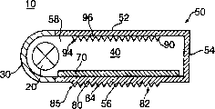
Fig. 1 a is the cutaway view of the illuminator of formation according to the present invention, and this illuminator has single source, hollow waveguide and two stacked light directional arrays, and the light oriented structure that is provided with on each light directional array is vertical mutually basically;
Fig. 1 b is the cutaway view of the illuminator of formation according to the present invention, this illuminator has single source, is essentially polygonal hollow waveguide and two stacked light directional arrays, and the light oriented structure that is provided with on each light directional array is vertical mutually basically and mutual to basically configuration;
Fig. 1 c is the cutaway view of the illuminator of formation according to the present invention, this illuminator has the single source that is positioned at illuminator output surface back, polygonal substantially hollow waveguide and two stacked light directional arrays, and the light oriented structure that is provided with on each light directional array is vertical mutually basically;
Fig. 1 d is the cutaway view of the illuminator that constitutes according to the present invention, and this illuminator has single source, polygonal substantially hollow waveguide and it is provided with the light directional array of light oriented structure;
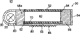
Fig. 2 a is the cutaway view of the illuminator of formation according to the present invention, and this illuminator has single source, is essentially hollow waveguide and two stacked light directional arrays of rectangle, and the light oriented structure that is provided with on each light directional array is vertical mutually basically;
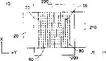
Fig. 2 b is the front view or the front view of the illuminator that constitutes according to the present invention shown in Fig. 2 a, and this illuminator has the light source that is provided with around a plurality of edges;
Fig. 3 is the cutaway view of the illuminator of formation according to the present invention, and this illuminator has single source, is essentially circular hollow waveguide and two stacked light directional arrays, and the light oriented structure that is provided with on each light directional array is vertical mutually basically;
Fig. 4 a is the cutaway view of the illuminator of formation according to the present invention, this illuminator has single point source of light, is essentially hollow waveguide and two stacked light directional arrays of annular, and the light oriented structure that is provided with on each light directional array is vertical mutually basically;
Fig. 4 b is the cutaway view of the illuminator of formation according to the present invention, it is radially the prismatic light directional array and the second ring light directional array of circular hollow waveguide, first substantially that this illuminator has, and the light oriented structure that is provided with on each light directional array is vertical mutually basically;
Fig. 4 c is the stereogram of illuminator shown in Fig. 4 b, expression and the stacked radially prismatic light directional array of annular prismatic light directional array;
Fig. 5 a is the cutaway view of the illuminator of formation according to the present invention, and this illuminator has single source, is essentially leg-of-mutton hollow waveguide and two stacked light directional arrays, and the light oriented structure that is provided with on each light directional array is vertical mutually basically;
Fig. 5 b is the front view of illuminator shown in Fig. 5 a, and this illuminator has the light source that is provided with around a plurality of edges;
Fig. 6 a is the perspective view of the first smooth directional array of formation according to the present invention;
Fig. 6 b is the perspective view of the second smooth directional array of formation according to the present invention;
Fig. 7 is the side view of the light directional array in the angle of expression light output and distributed area, angle;
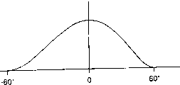
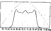
Fig. 8 is according to the theoretical light output distribution of the illuminator of preferred embodiment of the present invention formation and the curve map of intensity;
Fig. 9 a-9d is the detailed view according to various cylinder prism structures of the present invention;
Figure 10 is the curve map of the angle restriction of the polypropylene that calculates according to the present invention and Merlon light directional array.
Figure 11 is the curve map that the light with illuminator of reflection substrate according to the present invention is exported;
Figure 12 is the curve map that the light with illuminator of diffuse reflection substrate according to the present invention is exported.
The specific embodiment
The invention provides an illuminator with hollow waveguide, this hollow waveguide comprises the first and second smooth directional arrays (LDA), and each array has a plurality of thereon spacing and basic vertically disposed common cylinder prisms mutually.Light from light source enters waveguide, distributes from the light output side output waveguide and with predetermined flux (that is intensity) and angle and penetrate from illuminator from the light input side.Light output flow and angle distribute and all can independently be controlled by LDAs according to the present invention, so that the illuminator that can form various light output distributions and the requirement of intensity degree to be provided.
The term incidence angle of Shi Yonging and the angle of emergence are meant light and the angle of shooting normal to a surface perpendicular to light in this article.
Referring to accompanying drawing, figure 1 illustrates the illuminator of first embodiment of the invention.Illuminator 10 comprises a hollow waveguide 50 that is essentially rectangle, and hollow waveguide 50 has: make from the light of light source 20 and enter the light input side 58 of hollow waveguide 50, the light output side face 56 that is positioned at common mirrored sides 54, the substrate 52 on light input 58 opposites, side and is positioned at substrate 52 opposites and light is penetrated from the waveguide 50 of illuminator 10.Substrate 52, light output side face 56 and side 54 can utilize punching press, mould to annotate or other similar preparation method integrally constitutes.These parts also can be made respectively and be fixed together and form hollow waveguide 50 of the present invention.The position of light source 20 should be able to make its light that sends watch the angle at angle to enter hollow waveguide 50 with the normal direction (that is, 0 °) that is basically perpendicular to illuminator 10.This structure can be eliminated light " hot spot ", also the light of illuminator 10 outputs evenly be distributed.In addition, shown in Fig. 1 c, light source 20 can be positioned at hollow waveguide inside, makes light watch the angle parallel with normal direction basically.Though this structure can produce light " hot spot ", will be controlled from the angle distribution of illuminator 10 output light according to the present invention of following detailed description.In this article, term " hot spot " be meant the beholder watch light when output, the output light of illuminator is brighter at some point.
Passing through of the output light of the first and second smooth directional arrays (LDAs), 70,80 control hollow waveguide 50.In a preferred embodiment, the 2nd LDA80 comprises the light output side face 56 of hollow waveguide 50.LDAs70,80 is configured to distribute from the angle that LDAs70,80 light that penetrate are controlled the output light of illuminator 10 outside predetermined angle of cut-off from LDAs70,80 light that penetrate with by reflected back in predetermined angle of cut-off by refraction.In other words, having only the light that penetrates from hollow waveguide 50 is to be cut off the light within predetermined output angle distributes that the angle limits.Therefore, the light output that illuminator 10 of the present invention provides controllable and predetermined angle distributes.The light that penetrate with the angle outside the required angle of cut-off scope, from LDAs70,80 are along with the variation of their angles is reflected back in the optical channel 40, up to they by partial reflection substrate 52 (that is conduction LDA90) or in optical channel 40,, till they contact a LDA70 again.It is uniform basically that the light of the illuminator that this effective recirculation provided 10 of light in hollow waveguide 50 on its light output side face 56 distributes.
The example of a LDA70 shown in Fig. 6 a also is positioned at the optical channel 40 of waveguide 50, and comprises a plurality of common vertical cylinder prisms 74 that are used as the first smooth oriented structure 72 and towards the first smooth output surface 75 of the 2nd LDA80.In this example, though prism 74 also can be basically parallel to 58 location, light input side of waveguide 50, the direction of prism 74 is substantially perpendicular to light output side face 56 (in Fig. 6 a, by the indication of the y axle) location of hollow waveguide 50.(that is, prism 74 direction of) light oriented structure 72 itself is unimportant, and importantly the light oriented structure 82 with the 2nd LDA80 is vertical substantially for light oriented structure 72 for the one LDA70.Light enters a LDA70 by optical input surface 78, and optical input surface 78 is limited on the surface of a LDA70 who inwardly faces optical channel 40.Optical input surface 78 comprises the total inner surface of a LDA70 substantially, so can make the size of the fenestra that the light that enters a LDA70 passes through approximate the size of a LDA70.Though in fact all light of conduction all enter a LDA70 through optical input surface 78 when beginning in optical channel 40, have only some light to penetrate and enter the 2nd LDA80 from a LDA70.More specifically, the light oriented structure 72 control light of LDA70 penetrate from a LDA70, are transmitted to the 2nd LDA80 so that only have the light of predetermined angle distribution from a LDA70.So a LDA70 is configured to only allow some light to arrive the 2nd LDA80, and some other light reflected light passage 40.If hollow waveguide 50 has reflection substrate 52, then the light by LDA70 reflection will conduct in optical channel 40 with the azimuth that more or less changes, and also contact light oriented structure 72 once more or will arrive the far-end of optical channel 40 up to their by optical input surface 78 up to them.On the other hand,, hollow waveguide 50 reflects substrate, is LDA90 that then part will be by LDA90 and from substrate 52 ejaculations of hollow waveguide 50 by the light of LDA70 reflection if having partial reflection/part.
To being subjected to constituting the influence of the material of LDA on the one hand by a LDA70 with by the control of the light of LDA70 reflection, be subjected on the other hand cylinder prism 74 geometry, be the influence (hereinafter will at length discuss) of angle 76.Though preferable material is a polypropylene, the present invention also can consider other pure plastic material, and they include but not limited to pure Merlon, polystyrene, silicone, polyester and nylon.Each cylinder prism 74 of the one LDA70 limits the angle 76 of a control from the light of a LDA70 ejaculation, penetrates from a LDA70 so that only have the light of the angle of emergence that is less than or equal to required angle of cut-off.In this preferred embodiment, required angle of cut-off is about ± and 60 °.By along first direction, be that x direction control distributes from the angle that a LDA70 penetrates light among Fig. 2 b and the 6a, angle 76 controls of the prism 74 of a LDA70 distribute from the angle of illuminator 10 output light.Angle 76 is distributed by the refractive index of LDA (being determined by the material of making LDA), the angle that is input to the light of LDA and distributes definite from the required angle of the light of illuminator 10 outputs.Approximate 1.49 polypropylene LDAs for refractive index, and the light input angle of full hemisphere distributes and required output angle when being distributed between the pact ± 60 °, the scope of angle 76 is between about 115 ° and 121 °.The angle that those skilled in the art will appreciate that other will allow to pass through a LDA70 with the light that is greater than or less than the angle of emergence.So, the invention is not restricted to disclosed required angle of cut-off scope ± 55 °, and in fact can comprise all angle of cut-off scopes of symmetry (for example, ± 55 °), asymmetric (for example ,+30 ° ,-75 °) or other angle.Distribute for asymmetric output, the cylinder prism of LDA also is asymmetric.The detailed description that angle calculates will be described below.
The one LDA70 can freely be placed in the optical channel 40 or (see that Fig. 2 a) or utilize other known fastening or attachment device to be fixed on the hollow waveguide 50 by raceway groove or groove 62.
The 2nd LDA80 is positioned on the outer surface of hollow waveguide 50, and preferably and its formation integral body.In addition, the 2nd LDA80 can be formed on the inner surface of hollow waveguide 50, and shown in Fig. 1 b, in this case, the prism 74 of a LDA70 and the 2nd LDA80 prism 84 will be settled in the face of ground is close mutually.Though, between first and second LDAs70,80, needing roundabout coupling or contact, this contact does not influence performance of the present invention and operation.The 2nd LDA80 comprises a plurality of vertical cylinder prism 84 and irradiant second smooth output surfaces 85 that are used as the second smooth oriented structure 82.The second smooth oriented structure 82 basically with first smooth oriented structure 72 perpendicular positionings so that realize from hollow waveguide 50 irradiant controls at both direction.
The 2nd LDA80 to by its with carried out in the mode identical by the control of the light of its reflection with an above-mentioned LDA70.
In some illumination is used, when with about 0 ° when watching the angle to watch illuminator 10, when over against or the light that requires to provide maximum when watching illuminator 10 perpendicular to the direction of light output surface 85 export (below will illustrate in greater detail).This is watched the angle to be called as normal direction and watches the angle.Watch the light output intensity at angle to control for 0 ° by selecting substrate 52.For example, as shown in figure 11, when not influencing angle of cut-off when watch the angle to watch illuminator 10 from normal direction, reflection substrate 52 will cause more low intensive light output.On the other hand, as shown in figure 12, diffuse reflection substrate 52 will cause watching from normal direction the light output of the higher-strength at angle.The angle that also needs to control light output distributes, so that realize than even light distribution, promptly eliminating hot spot in the angular region in required watching.Preferably, from the output of the light of hollow waveguide (that is) from illuminator 10 needs watch the angular region planted agent very even, when with required when watching angle angular region outside to watch, in fact will not exist light to export.So, distribute to define from the angle of hollow waveguide 50 light output and watch angular region, outside this scope, in fact detect the light that penetrates less than from illuminator 10.In fact surpass the angle of just detecting at that time of watching and be known as angle of cut-off less than light.As non-limiting example, below detailed description had the illuminator 10 of pact ± 60 ° of angles of cut-off.Those skilled in the art as can be known, this angle of cut-off scope is of the present invention schematically illustrating and non-limiting example, the present invention also can have the greater or lesser angular region of watching.
The present invention penetrates from hollow waveguide 50 at both direction control light.Specifically referring to Fig. 2 b, the figure shows the view of watching the illuminator 10 at angle in normal direction, a LDA70 distributes at the angle of x direction control light output, and the 2nd LDA80 distributes at the angle of y direction control light output.Therefore, when watching when watching in the angular region required, the present invention is uniformly from the light output of illuminator 10 basically, and has eliminated the photo-thermal spot effectively.Change one or two angle among first and second LDAs70,80 and can control angular region from the light output of illuminator 10.
In a preferred embodiment, to be distributed in the output angle scope that is limited be uniform for light output.When watch the angle from 0 ° to both direction (that is, positive direction or negative direction) when removing, descend from the luminous intensity of illuminator 10 outputs, when arriving an angle of cut-off, the beholder can't see enough light quantities and sends from illuminator 10.This curve by Fig. 8 illustrates, and wherein, angle of cut-off approximates ± and 60 °.The angle of one or two among the change LDA70,80 then can change angle of cut-off.
In another embodiment, shown in Fig. 1 d, illuminator 10 of the present invention can have single LDA80.Distributing from the angle of the light of this illuminator 10 outputs still can be as controlling according to the present invention the described embodiment of Fig. 1 a, and unique not being both can distribute by pilot angle on single direction.In others, the operation of illuminator 10 shown in Fig. 1 d is basic identical with the operation of system 10 shown in above-mentioned Fig. 1 a.
Fig. 2 a represents second embodiment of illuminator 10 of the present invention.Conventional rectangle or foursquare hollow waveguide 50 comprise the light input side 58a of entity, and side 58a limits the optical receiving surface of settling near light source 20 60.Terminology used here " near " be abutment and the contact that almost is close together, promptly should be less than or equal to one inch.The light input side 58a of entity makes light source 20 physically separate and be connected optically with optical channel 40.Reflector 30 is around light source 20 and with the light light input side 58a of the entity of guided waveguides 50 again.Hollow waveguide 50 comprises light output side face 56, side 56 can constitute by a LDA70 with the 2nd LDA80, each LDA70,80 has the common cylinder prism 74,84 that limits on it, limits orthogonal substantially corresponding light oriented structure 72,82 on the prism 74,84.The one LDA70 can freely be placed in the optical channel 40 of hollow waveguide 50 or can fix by groove or raceway groove 62.The 2nd LDA80 is best and hollow waveguide 50 formations are whole, and can make by punching press, mould notes or other similar shaping processing.Hollow waveguide 50 comprises and can reflect or can partial reflection and the substrate 52 of part refraction (that is, diffusion) that in this case, substrate 52 comprises LDA90.No matter under which kind of situation, substrate 52 is arranged in groove or the raceway groove 64 of the light input side 58a that is limited at entity.
In operation, enter optical channel 40 from the light contact optical receiving surface 60 of light source 20 and through the light input side 58a of entity.Some light pass optical channel 40 and arrive the side 54 that is positioned at entity light input 58a opposite, side and be reflected back toward optical channel 40.Some light can contact base (back) plate 52 and also be reflected back toward optical channel 40, and simultaneously, other light will contact the optical input surface 78 of a LDA70 and enter a LDA70.These light distribute based on its angle, or reflected back passage 40 or penetrate from a LDA70.The light that penetrates from a LDA70 will contact the optical input surface 88 of the 2nd LDA80 and enter the 2nd LDA80.Have only the angle be distributed as ± those light of 60 ° penetrate from the 2nd LDA80 by light output surface 85.
The embodiment of Fig. 2 a also can comprise nearly three three additional source of light 200,210,220 shown in Fig. 2 b.The illuminator 10 of this embodiment has identical functions with the described embodiment of above Fig. 2 a substantially.Certainly, additional source of light 200 provides additional light, so the light output intensity of this embodiment is greater than the embodiment of Fig. 2 a.About the reflection and the refraction of light in hollow waveguide 50 and by LDAs70,80 (if providing), the explanation that Fig. 2 a embodiment is provided can be used for the embodiment of Fig. 2 b with being equal to.
Fig. 3 is another embodiment of the present invention, and wherein, illuminator 10 comprises the hollow circular waveguide 50 that is centered on by common annular light source 20.Basic and the foregoing description of the illuminator 10 of present embodiment has identical functions.
Fig. 4 a is another embodiment of the present invention, and wherein, common transversal hollow waveguide 50 is around a common point source of light 20.The light source 20 of present embodiment can comprise single lamp or lamp array.In addition, the illuminator 10 of present embodiment is basic and the foregoing description has identical functions.
Basic vertical relation between first and second LDA70,80 required for the present invention clearly illustrates that in Fig. 4 b and 4c, wherein, illuminator 10 comprises circular waveguide 50, have a LDA70 on the circular waveguide 50, the LDA70 with prism 74 radially is stacked with the 2nd LDA80 of the annular prism 84 with concentric setting.As long as can be in each position relative circular waveguide 50 keeps the vertical substantially relation between these stacked LDAs70,80 the light oriented structure 72,82 (that is, between the prism 74,84), then can change the configuration of the specific light oriented structure 72,82 of each LDA.For example, the specific light oriented structure in LDA 72,82 can constitute clockwise direction and counterclockwise common scroll lens array.
Referring to Fig. 5 a, illuminator 10 of the present invention comprises the triangle hollow waveguide 50 with light source 20 below.Shown in Fig. 5 b, also can provide the second and the 3rd light source 200,210.Basic and the foregoing description of the illuminator 10 of present embodiment has identical functions.
In above-mentioned each embodiment, the 2nd LDA80 can constitute wholely with hollow waveguide 50, or forms respectively with hollow waveguide 50 and fixes and attachment techniques is fixed on the hollow waveguide 50 with existing.For above-mentioned each embodiment, as long as the basic vertical relation that keeps between the first and second smooth oriented structures 72,82, then the cylinder prism 84 and the second smooth oriented structure 82 both can be shown in Fig. 1 b is positioned at optical channel 40, also can be positioned at outside the waveguide 50 as shown in Figure 1a.When the second smooth oriented structure 82 was positioned at optical channel 40, cylinder prism 84 was total internal reflections, and all penetrate from hollow waveguide 50 by surface 85 and the light that enters the 2nd LDA80.
Term used herein " vertical substantially " is meant the relation between the first and second smooth oriented structures 72,82, the angle of its qualification should between 80 ° and 100 °, preferably between 85 ° and 95 °, preferably 90 °.
Though this paper discloses the LDAs70,80,90 with a plurality of common cylinder prisms, prism the present invention of various geometries and structure all can use.Shown in Fig. 9 a, prism should have the spike 44 of straight basically sidewall 42 and sharp outline particularly.In addition, this prism can have the peak (seeing Fig. 9 b) on crooked sidewall 42 and smooth basically or plane.Shown in Fig. 9 c, prism also can have the spike 42 of another kind of crooked sidewall 42 and sharp outline.In addition, shown in Fig. 9 d, prism also can have a plurality of sides.Those skilled in the art as can be known, the present invention also can use the prism of other planform.
Light directional array 70,80,90 can be made with any transparent material.The refractive index of preferred material is more than or equal to 1.03, and these materials comprise glass, polymethyl methacrylate, Merlon, polyester, polystyrene and other polymer that is formed by the acrylate monomers photopolymerization.The preferred material ranges of indices of refraction is between 1.04 to 1.70.Those skilled in the art has bigger or less refractive index materials and also can be used for the present invention as can be known.
The angle that specifies the prism with basic straight sidewall below (sees that Fig. 9 a) and the calculating of the angle of basic symmetrical angle of cut-off.Angle depends on that the light output of the refractive index of the material that constitutes LDA, required angle distributes and the angular distribution of input light.The variable and the constant definition that calculate usefulness are as follows:
The angle of w=prism;
The angle of cut-off that C=is required;
The refractive index of n=prism material.
Referring to Fig. 7, following equation defines to from having ± required condition when angle that any angle of the output light of the hollow waveguide 50 of 90 ° angle of cut-off C distributes calculates.
w/2≤C (1)
w≥2(2*asin(1/n)+90)/3 (2)
tan(w/2)≤(n*sin(asin(1/n)3w/2)+
cos(w/2))/(n*cos(asin(1/n)-3w/2)+sin(w/2)) (3)
The diagram of equation 3 the results are shown among Figure 10.
As an example, when angle output distribute ± 60 ° approximately, when refractive index n=1.49 (acrylic acid LDA), equation 1 requires w≤120 °.Then calculation equation 2, w 〉=116 °.At last, shown in the solid line triangular plot among Figure 10, the upper limit of w is about 121.5 °.So angle is between 116 ° to 120 °.
For having the Merlon LDA that the output of refractive index n=1.59 and same angular distributes, equation 2 requires w 〉=112 °.Referring again to the chart of Figure 10, the upper limit of w (being expressed by triangular graph clearly) is about 118.1 °.So angle is between 112 ° to 118.1 °.
For the prism with sidewall crooked or other structure, minimum and maximum angle will satisfy the condition that is limited by equation (1), (2) and (3).
More than the detailed description that the present invention did is not limited the present invention, those skilled in the art can make the present invention and be in scope of the present invention that appended claims limits and various variations and the remodeling in the design.
Claims (51)
1. one kind is used to distribute from the illuminator of the light of a light source, and described illuminator comprises:
A hollow waveguide, hollow waveguide have one makes the light from light source enter the light input side of hollow waveguide and make the light output side of light from the hollow waveguide ejaculation;
One first smooth directional array limits the first smooth oriented structure on it;
One second smooth directional array, limit the second smooth oriented structure on it, the described first and second smooth oriented structures are mutually vertical basically to be provided with, and the described second smooth directional array comprises described light output side, penetrates from described light output side from the light of described hollow waveguide;
The described first and second smooth oriented structures distribute from the angle that an angle of cut-off of the light of described illuminator output is controlled described illuminator output light by qualification.
2. illuminator as claimed in claim 1, it is characterized in that, the described first smooth oriented structure comprises a plurality of cylinder prisms that are limited on the described first smooth directional array, the described second smooth oriented structure comprises a plurality of cylinder prisms that are limited on the described second smooth directional array, the described prism of each of the described first and second smooth oriented structures has an angle that limits on it, and it is restricted to 89 ° or the littler described illuminator that is used for and exports photodistributed angle of cut-off.
3. an illuminator as claimed in claim 2 is characterized in that, when when profile direction is watched, the described prism of each of the described first and second smooth oriented structures comprises straight basically sidewall.
4. an illuminator as claimed in claim 2 is characterized in that, when when profile direction is watched, the described prism of each of the described first and second smooth oriented structures comprises curved sidewall basically.
5. an illuminator as claimed in claim 2 is characterized in that, when when profile direction is watched, the described prism of each of the described first and second smooth oriented structures comprises the sidewall of a plurality of sides.
6. an illuminator as claimed in claim 2 is characterized in that, when when profile direction is watched, the described prism of each of the described first and second smooth oriented structures is symmetrical basically, and limits an angle, and it is calculated by equation:
w/2≤C
w≥2(2*asin(1/n)+90)/3
tan(w/2)≤(n*sin(asin(1/n)-3w/2)+
cos(w/2))/(n*cos(asin(1/n)-3w/2)+sin(w/2))
Wherein, w is the angle of each described cylinder prism, and C is that n is the refractive index of prism material from the required angle of cut-off of described illuminator output light.
7. an illuminator as claimed in claim 1 is characterized in that, described angle of cut-off scope is approximately between+60 ° and-60 °.
8. illuminator as claimed in claim 1, it is characterized in that, the described first and second smooth directional arrays are made by polypropylene material, the described first smooth oriented structure comprises a plurality of vertical cylinder prisms that are limited on the described first smooth directional array, the described second smooth oriented structure comprises a plurality of vertical cylinder prisms that are limited on the described second smooth directional array, and the described prism of each of the described first and second smooth oriented structures has the angle between about 115 ° to 121 °.
9. the illuminator of a claim 8 is characterized in that, described angle is about 116 °.
10. illuminator as claimed in claim 1, it is characterized in that, the described first and second smooth directional arrays are made by Merlon or polystyrene material, the described first smooth oriented structure comprises a plurality of vertical cylinder prisms that are limited on the described first smooth directional array, the described second smooth oriented structure comprises a plurality of vertical cylinder prisms that are limited on the described second smooth directional array, and the described prism of each of the described first and second smooth oriented structures has the angle between about 111 ° to 119 °.
11. the illuminator of a claim 10 is characterized in that, described angle is about 113 °.
12. an illuminator as claimed in claim 1 is characterized in that, the longitudinal axis that light source limits is arranged essentially parallel to the described light input side of described hollow waveguide, and the described smooth oriented structure of the described second smooth directional array is basically perpendicular to the longitudinal axis of light source.
13. an illuminator as claimed in claim 1 is characterized in that, the longitudinal axis that light source limits is arranged essentially parallel to the described light input side of described hollow waveguide, and the described smooth oriented structure of the described second smooth directional array is basically parallel to the longitudinal axis of light source.
14. an illuminator as claimed in claim 1 is characterized in that, light penetrates from described hollow waveguide through described light output side face with an angle, and this angle is substantially perpendicular to light enters described hollow waveguide through described light input side angle.
15. the illuminator as claim 14 is characterized in that, described light input side also comprises the entity part of being made by transparent material.
16. an illuminator as claimed in claim 1 is characterized in that, light penetrates from described hollow waveguide through described light output side face with an angle, and this angle is arranged essentially parallel to light enters described hollow waveguide through described light input side angle.
17. an illuminator as claimed in claim 1 is characterized in that, described hollow waveguide also comprises a reflection substrate, and this reflection substrate makes from the inner next light of described hollow waveguide and can not pass through.
18. an illuminator as claimed in claim 1 is characterized in that, described hollow waveguide also comprises a diffuse reflection substrate, and this diffuse reflection substrate makes from the inner next predetermined light amount of described hollow waveguide and passes through.
19. the illuminator as claim 18 is characterized in that, described diffuse reflection substrate also comprises the 3rd a smooth directional array that is limited with the light oriented structure on it.
20. the illuminator as claim 19 is characterized in that, described smooth oriented structure comprises a plurality of vertical cylinder prisms that are limited on the described the 3rd smooth directional array, and each described prism has the angle between about 90 ° to 120 °.
21. an illuminator as claimed in claim 1 is characterized in that, the described smooth oriented structure of the described second smooth directional array is arranged in the described hollow waveguide.
22. an illuminator as claimed in claim 1 is characterized in that, the described smooth oriented structure of the described second smooth directional array is arranged on outside the described hollow waveguide.
23. an illuminator as claimed in claim 1 is characterized in that, described waveguide is rectangle substantially.
24. an illuminator as claimed in claim 1 is characterized in that, described waveguide is circular substantially.
25. illuminator as claimed in claim 2, it is characterized in that, be limited to the described cylinder prism location radially each other on one of described first and second smooth directional arrays array, the described cylinder prism that is limited on another arrays of the described first and second smooth directional arrays disposes concentrically with respect to one another.
26. an illuminator as claimed in claim 1 is characterized in that, described hollow waveguide is leg-of-mutton substantially.
27. one kind is used to distribute from the illuminator of the light of a light source, this light source has longitudinal axis, and described illuminator comprises:
One is the hollow waveguide of rectangle substantially, and hollow waveguide has one makes the light from light source enter the light input side of hollow waveguide and make the light output side of light from the hollow waveguide ejaculation;
One first smooth directional array is limited with the first smooth oriented structure on it;
One second smooth directional array, be limited with the second smooth oriented structure on it, the described first and second smooth oriented structures are mutually vertical basically to be provided with, and the described second smooth directional array comprises described light output side, penetrates from described light output side from the light of described hollow waveguide;
The described first and second smooth oriented structures distribute from the angle that an angle of cut-off of the light of described illuminator output is controlled described illuminator output light by qualification.
28. illuminator as claim 27, it is characterized in that, the described first smooth oriented structure comprises a plurality of vertical cylinder prisms that are limited on the described first smooth directional array, the described second smooth oriented structure comprises a plurality of vertical cylinder prisms that are limited on the described second smooth directional array, the described prism of each of the described first and second smooth oriented structures has an angle that limits on it, and it is restricted to 89 ° or littler be used for the angle of cut-off that described illuminator light output distributes.
29. the illuminator as claim 28 is characterized in that, when when profile direction is watched, the described prism of each of the described first and second smooth oriented structures comprises straight basically sidewall.
30. the illuminator as claim 28 is characterized in that, when when profile direction is watched, the described prism of each of the described first and second smooth oriented structures comprises curved sidewall basically.
31. the illuminator as claim 28 is characterized in that, when when profile direction is watched, the described prism of each of the described first and second smooth oriented structures comprises the sidewall of a plurality of sides.
32. the illuminator as claim 28 is characterized in that, when when profile direction is watched, the described prism of each of the described first and second smooth oriented structures is symmetrical and limits an angle that it is calculated by following equation basically:
w/2≤C
w≥2(2*asin(1/n)+90)/3
tan(w/2)≤(n*sin(asin(1/n)-3w/2)+
cos(w/2))/(n*cos(asin(1/n)-3w/2)+sin(w/2))
Wherein, w is the angle of each described cylinder prism, and C is that n is the refractive index of prism material from the required angle of cut-off of described illuminator output light.
33. an illuminator as claimed in claim 1 is characterized in that, described angle of cut-off scope is approximately between+60 ° and-60 °.
34. illuminator as claim 27, it is characterized in that, the described first and second smooth directional arrays are made by polypropylene material, the described first smooth oriented structure comprises a plurality of vertical cylinder prisms that are limited on the described first smooth directional array, the described second smooth oriented structure comprises a plurality of vertical cylinder prisms that are limited on the described second smooth directional array, and the described prism of each of the described first and second smooth oriented structures has the angle between about 115 ° to 121 °.
35. the illuminator of a claim 34 is characterized in that, described angle is about 116 °.
36. the illuminator as claim 27 is characterized in that, the longitudinal axis that light source limits is arranged essentially parallel to the described light input side of described hollow waveguide, and the described smooth oriented structure of the described second smooth directional array is basically perpendicular to the longitudinal axis of light source.
37. the illuminator as claim 27 is characterized in that, the longitudinal axis that light source limits is arranged essentially parallel to the described light input side of described hollow waveguide, and the described smooth oriented structure of the described second smooth directional array is basically parallel to the longitudinal axis of light source.
38. the illuminator as claim 27 is characterized in that, light penetrates from described hollow waveguide through described light output side face with an angle, and this angle is substantially perpendicular to light enters described hollow waveguide through described light input side angle.
39. the illuminator as claim 38 is characterized in that, described light input side also comprises the entity part of being made by transparent material.
40. the illuminator as claim 27 is characterized in that, described hollow waveguide also comprises a reflection substrate, and this reflection substrate makes from the inner next light of described hollow waveguide and can not pass through.
41. the illuminator as claim 27 is characterized in that, described hollow waveguide also comprises a diffuse reflection substrate, and this diffuse reflection substrate makes from the inner next predetermined light amount of described hollow waveguide and passes through.
42. the illuminator as claim 41 is characterized in that, described diffuse reflection substrate also comprises the 3rd a smooth directional array that is limited with the light oriented structure on it.
43. the illuminator as claim 42 is characterized in that, described smooth oriented structure comprises a plurality of vertical cylinder prisms that are limited on the described the 3rd smooth directional array, and each described prism has the angle between about 90 ° to 120 °.
44. the illuminator as claim 27 is characterized in that, the described smooth oriented structure of the described second smooth directional array is arranged within the described hollow waveguide.
45. the illuminator as claim 27 is characterized in that, the described smooth oriented structure of the described second smooth directional array is arranged on outside the described hollow waveguide.
46. illuminator as claim 27, it is characterized in that, the described first and second smooth directional arrays are made by Merlon or polystyrene material, the described first smooth oriented structure comprises a plurality of vertical cylinder prisms that are limited on the described first smooth directional array, the described second smooth oriented structure comprises a plurality of vertical cylinder prisms that are limited on the described second smooth directional array, and the described prism of each of the described first and second smooth oriented structures has the angle between about 111 ° to 119 °.
47. the illuminator of a claim 46 is characterized in that, described angle is about 113 °.
48. one kind is used to distribute from the illuminator of the light of a light source, described illuminator comprises:
A hollow waveguide, hollow waveguide have one makes the light from light source enter the light input side of hollow waveguide and make the light output side of light from the hollow waveguide ejaculation;
A light directional array, it has a plurality of from the outwards outstanding angled ridge of hollow waveguide, is used for distributing from the angle that an angle of cut-off of the light of described illuminator output is controlled described illuminator output light by qualification at single direction.
49. the illuminator as claim 48 is characterized in that, described angled ridge has the angle that includes that is defined in it, and its restriction angle of cut-off is 89 ° or littler, is used for the distribution of described illuminator light output.
50. the illuminator as claim 48 is characterized in that, described angular range is between about 110 ° to 121 °.
51. the illuminator as claim 48 is characterized in that, described angle of cut-off scope is approximately between+60 ° and-60 °.
Applications Claiming Priority (2)
| Application Number | Priority Date | Filing Date | Title |
|---|---|---|---|
| US09/151,089 US6185357B1 (en) | 1998-09-10 | 1998-09-10 | Illumination system using edge-illuminated hollow waveguide and lenticular optical structures |
| US09/151,089 | 1998-09-10 |
Publications (2)
| Publication Number | Publication Date |
|---|---|
| CN1325484A CN1325484A (en) | 2001-12-05 |
| CN1134606C true CN1134606C (en) | 2004-01-14 |
Family
ID=22537271
Family Applications (1)
| Application Number | Title | Priority Date | Filing Date |
|---|---|---|---|
| CNB998131326A Expired - Fee Related CN1134606C (en) | 1998-09-10 | 1999-09-09 | Illumination system using edge-illuminated hollow waveguide and lenticular optical structures |
Country Status (10)
| Country | Link |
|---|---|
| US (1) | US6185357B1 (en) |
| EP (1) | EP1114278B1 (en) |
| JP (1) | JP2002525791A (en) |
| KR (1) | KR100637907B1 (en) |
| CN (1) | CN1134606C (en) |
| AT (1) | ATE283447T1 (en) |
| AU (1) | AU5819299A (en) |
| CA (1) | CA2343281C (en) |
| DE (1) | DE69922224T2 (en) |
| WO (1) | WO2000016006A1 (en) |
Cited By (1)
| Publication number | Priority date | Publication date | Assignee | Title |
|---|---|---|---|---|
| CN101681053B (en) * | 2007-05-20 | 2012-03-21 | 3M创新有限公司 | Recycling backlights with semi-specular components |
Families Citing this family (58)
| Publication number | Priority date | Publication date | Assignee | Title |
|---|---|---|---|---|
| US6305811B1 (en) * | 1998-09-25 | 2001-10-23 | Honeywell International Inc. | Illumination system having an array of linear prisms |
| NZ515195A (en) * | 1999-05-20 | 2003-04-29 | Zumtobel Staff Gmbh | Lighting optical element for uniform light distribution and anti dazzling effects |
| ATE365889T1 (en) † | 1999-05-25 | 2007-07-15 | Siteco Beleuchtungstech Gmbh | PENDANT LAMP WITH INDIRECT LIGHT Emission |
| EP1059484B2 (en) † | 1999-05-25 | 2014-05-14 | Siteco Beleuchtungstechnik GmbH | Luminaire with wide beam light intensity distribution |
| DE10011378B4 (en) * | 1999-05-25 | 2013-07-25 | Siteco Beleuchtungstechnik Gmbh | Hollow-light luminaire with indirect light emission |
| ATE317525T1 (en) | 1999-12-01 | 2006-02-15 | Siteco Beleuchtungstech Gmbh | LIGHT GUIDE LUMINAIRE WITH A NON-UNIFORM LIGHT REFRACTIVE STRUCTURE |
| DE10011516A1 (en) * | 2000-03-09 | 2001-09-20 | Siteco Beleuchtungstech Gmbh | Lighting system |
| DE10042651C2 (en) * | 2000-05-08 | 2002-10-02 | Poellet Wilfried | Workplace lighting |
| US20040047154A1 (en) * | 2000-08-15 | 2004-03-11 | Miller Jack V. | Tracklight system |
| EP1440346A1 (en) * | 2001-11-02 | 2004-07-28 | Honeywell International Inc. | Hollow wedge shape light guide for back illumination |
| KR100978057B1 (en) * | 2001-11-02 | 2010-08-26 | 허니웰 인터내셔널 인코포레이티드 | Hollow wedge shape light guide for back illumination |
| US6960872B2 (en) * | 2003-05-23 | 2005-11-01 | Goldeneye, Inc. | Illumination systems utilizing light emitting diodes and light recycling to enhance output radiance |
| US7040774B2 (en) * | 2003-05-23 | 2006-05-09 | Goldeneye, Inc. | Illumination systems utilizing multiple wavelength light recycling |
| US7258467B2 (en) * | 2004-03-12 | 2007-08-21 | Honeywell International, Inc. | Low profile direct/indirect luminaires |
| US20050201103A1 (en) * | 2004-03-12 | 2005-09-15 | Honeywell International Inc. | Luminaires with batwing light distribution |
| US7195374B2 (en) * | 2004-03-12 | 2007-03-27 | Honeywell International, Inc. | Luminaires for artificial lighting |
| US7497581B2 (en) * | 2004-03-30 | 2009-03-03 | Goldeneye, Inc. | Light recycling illumination systems with wavelength conversion |
| US7025464B2 (en) * | 2004-03-30 | 2006-04-11 | Goldeneye, Inc. | Projection display systems utilizing light emitting diodes and light recycling |
| US7431463B2 (en) * | 2004-03-30 | 2008-10-07 | Goldeneye, Inc. | Light emitting diode projection display systems |
| US7048385B2 (en) * | 2004-06-16 | 2006-05-23 | Goldeneye, Inc. | Projection display systems utilizing color scrolling and light emitting diodes |
| JP2006091821A (en) * | 2004-08-26 | 2006-04-06 | Fuji Photo Film Co Ltd | Prism sheet and display device using the same |
| US7348786B2 (en) * | 2004-08-31 | 2008-03-25 | Georgia Tech Research Corporation | Probe module for testing chips with electrical and optical input/output interconnects, methods of use, and methods of fabrication |
| US7370993B2 (en) * | 2004-09-28 | 2008-05-13 | Goldeneye, Inc. | Light recycling illumination systems having restricted angular output |
| US7352006B2 (en) * | 2004-09-28 | 2008-04-01 | Goldeneye, Inc. | Light emitting diodes exhibiting both high reflectivity and high light extraction |
| US20080247172A1 (en) * | 2004-09-28 | 2008-10-09 | Goldeneye, Inc. | Light recycling illumination systems having restricted angular output |
| US7352124B2 (en) * | 2004-09-28 | 2008-04-01 | Goldeneye, Inc. | Light recycling illumination systems utilizing light emitting diodes |
| US7331691B2 (en) * | 2004-10-29 | 2008-02-19 | Goldeneye, Inc. | Light emitting diode light source with heat transfer means |
| US7360929B2 (en) * | 2005-04-15 | 2008-04-22 | Sylvan R. Shemitz Designs, Inc. | Luminaire with multi-purpose mounting feature |
| US7293908B2 (en) * | 2005-10-18 | 2007-11-13 | Goldeneye, Inc. | Side emitting illumination systems incorporating light emitting diodes |
| US7378686B2 (en) * | 2005-10-18 | 2008-05-27 | Goldeneye, Inc. | Light emitting diode and side emitting lens |
| FR2904404A1 (en) * | 2006-07-27 | 2008-02-01 | Regenerer Sarl | DEVICE FOR PRODUCING LIGHT AND ITS APPLICATIONS TO LIGHTING AND LIGHT SIGNALING |
| KR100829015B1 (en) * | 2006-08-22 | 2008-05-14 | 엘지전자 주식회사 | Surface light source, back light unit and liquid crystal display having the same |
| WO2008029911A1 (en) * | 2006-09-08 | 2008-03-13 | Kuraray Co., Ltd. | Planar light source element, light control member using the same, and image display device using the same |
| US20080101759A1 (en) * | 2006-10-26 | 2008-05-01 | K Laser Technology, Inc. | Prism matrix with random phase structures |
| KR100942490B1 (en) * | 2007-09-05 | 2010-02-12 | 제일모직주식회사 | Light guide panel for LCD back light unit and LCD back light unit thereby |
| JP5600121B2 (en) | 2009-01-15 | 2014-10-01 | スリーエム イノベイティブ プロパティズ カンパニー | Light block |
| US8026997B2 (en) * | 2009-01-28 | 2011-09-27 | Sharp Laboratories Of America, Inc. | Area active backlight with steerable light source |
| WO2010146664A1 (en) * | 2009-06-16 | 2010-12-23 | 株式会社エス・テー・アイ・ジャパン | Led illuminator, and thin, surface light-emitting device |
| KR20120052289A (en) * | 2009-07-09 | 2012-05-23 | 코닌클리즈케 필립스 일렉트로닉스 엔.브이. | Free form lighting module |
| US9690029B2 (en) | 2013-01-30 | 2017-06-27 | Cree, Inc. | Optical waveguides and luminaires incorporating same |
| US10436969B2 (en) | 2013-01-30 | 2019-10-08 | Ideal Industries Lighting Llc | Optical waveguide and luminaire incorporating same |
| US9291320B2 (en) | 2013-01-30 | 2016-03-22 | Cree, Inc. | Consolidated troffer |
| US9366396B2 (en) | 2013-01-30 | 2016-06-14 | Cree, Inc. | Optical waveguide and lamp including same |
| US9869432B2 (en) | 2013-01-30 | 2018-01-16 | Cree, Inc. | Luminaires using waveguide bodies and optical elements |
| US9442243B2 (en) | 2013-01-30 | 2016-09-13 | Cree, Inc. | Waveguide bodies including redirection features and methods of producing same |
| US9625638B2 (en) | 2013-03-15 | 2017-04-18 | Cree, Inc. | Optical waveguide body |
| US9798072B2 (en) | 2013-03-15 | 2017-10-24 | Cree, Inc. | Optical element and method of forming an optical element |
| US10379278B2 (en) * | 2013-03-15 | 2019-08-13 | Ideal Industries Lighting Llc | Outdoor and/or enclosed structure LED luminaire outdoor and/or enclosed structure LED luminaire having outward illumination |
| US10502899B2 (en) * | 2013-03-15 | 2019-12-10 | Ideal Industries Lighting Llc | Outdoor and/or enclosed structure LED luminaire |
| US9366799B2 (en) | 2013-03-15 | 2016-06-14 | Cree, Inc. | Optical waveguide bodies and luminaires utilizing same |
| US10209429B2 (en) | 2013-03-15 | 2019-02-19 | Cree, Inc. | Luminaire with selectable luminous intensity pattern |
| US10436970B2 (en) | 2013-03-15 | 2019-10-08 | Ideal Industries Lighting Llc | Shaped optical waveguide bodies |
| CN104501094B (en) * | 2014-12-02 | 2017-10-13 | 深圳市华星光电技术有限公司 | Light guide plate, backlight module and display device |
| AT16410U1 (en) * | 2015-10-09 | 2019-08-15 | Zumtobel Lighting Gmbh | Arrangement for surface light emission |
| US11719882B2 (en) | 2016-05-06 | 2023-08-08 | Ideal Industries Lighting Llc | Waveguide-based light sources with dynamic beam shaping |
| US10416377B2 (en) | 2016-05-06 | 2019-09-17 | Cree, Inc. | Luminaire with controllable light emission |
| DE102016011216A1 (en) | 2016-09-16 | 2018-03-22 | Bartenbach Holding Gmbh | lighting device |
| DE102019103855B4 (en) * | 2019-02-15 | 2021-09-30 | Lisa Dräxlmaier GmbH | Vehicle interior lighting device |
Family Cites Families (14)
| Publication number | Priority date | Publication date | Assignee | Title |
|---|---|---|---|---|
| US4260220A (en) | 1979-06-15 | 1981-04-07 | Canadian Patents And Development Limited | Prism light guide having surfaces which are in octature |
| US4542449A (en) | 1983-08-29 | 1985-09-17 | Canadian Patents & Development Limited | Lighting panel with opposed 45° corrugations |
| US4615579A (en) | 1983-08-29 | 1986-10-07 | Canadian Patents & Development Ltd. | Prism light guide luminaire |
| US4984144A (en) * | 1987-05-08 | 1991-01-08 | Minnesota Mining And Manufacturing Company | High aspect ratio light fixture and film for use therein |
| US5190370A (en) | 1991-08-21 | 1993-03-02 | Minnesota Mining And Manufacturing Company | High aspect ratio lighting element |
| US5676453A (en) | 1992-04-16 | 1997-10-14 | Tir Technologies, Inc. | Collimating TIR lens devices employing fluorescent light sources |
| US5404869A (en) | 1992-04-16 | 1995-04-11 | Tir Technologies, Inc. | Faceted totally internally reflecting lens with individually curved faces on facets |
| US5339382A (en) * | 1993-02-23 | 1994-08-16 | Minnesota Mining And Manufacturing Company | Prism light guide luminaire with efficient directional output |
| US5428468A (en) | 1993-11-05 | 1995-06-27 | Alliedsignal Inc. | Illumination system employing an array of microprisms |
| US5555329A (en) | 1993-11-05 | 1996-09-10 | Alliesignal Inc. | Light directing optical structure |
| US5396350A (en) | 1993-11-05 | 1995-03-07 | Alliedsignal Inc. | Backlighting apparatus employing an array of microprisms |
| US5521725A (en) | 1993-11-05 | 1996-05-28 | Alliedsignal Inc. | Illumination system employing an array of microprisms |
| US5598281A (en) | 1993-11-19 | 1997-01-28 | Alliedsignal Inc. | Backlight assembly for improved illumination employing tapered optical elements |
| KR19980703642A (en) * | 1996-02-07 | 1998-12-05 | 고이께야스히로 | Surface light source device, liquid crystal display and asymmetric prism sheet |
-
1998
- 1998-09-10 US US09/151,089 patent/US6185357B1/en not_active Expired - Lifetime
-
1999
- 1999-09-09 KR KR1020017003090A patent/KR100637907B1/en not_active IP Right Cessation
- 1999-09-09 JP JP2000570502A patent/JP2002525791A/en active Pending
- 1999-09-09 AU AU58192/99A patent/AU5819299A/en not_active Abandoned
- 1999-09-09 DE DE69922224T patent/DE69922224T2/en not_active Expired - Lifetime
- 1999-09-09 CA CA002343281A patent/CA2343281C/en not_active Expired - Fee Related
- 1999-09-09 AT AT99945624T patent/ATE283447T1/en active
- 1999-09-09 CN CNB998131326A patent/CN1134606C/en not_active Expired - Fee Related
- 1999-09-09 WO PCT/US1999/020710 patent/WO2000016006A1/en active IP Right Grant
- 1999-09-09 EP EP99945624A patent/EP1114278B1/en not_active Expired - Lifetime
Cited By (1)
| Publication number | Priority date | Publication date | Assignee | Title |
|---|---|---|---|---|
| CN101681053B (en) * | 2007-05-20 | 2012-03-21 | 3M创新有限公司 | Recycling backlights with semi-specular components |
Also Published As
| Publication number | Publication date |
|---|---|
| EP1114278A1 (en) | 2001-07-11 |
| DE69922224T2 (en) | 2005-11-24 |
| CN1325484A (en) | 2001-12-05 |
| DE69922224D1 (en) | 2004-12-30 |
| WO2000016006A1 (en) | 2000-03-23 |
| AU5819299A (en) | 2000-04-03 |
| EP1114278B1 (en) | 2004-11-24 |
| KR100637907B1 (en) | 2006-10-24 |
| ATE283447T1 (en) | 2004-12-15 |
| KR20010086401A (en) | 2001-09-10 |
| JP2002525791A (en) | 2002-08-13 |
| CA2343281A1 (en) | 2000-03-23 |
| US6185357B1 (en) | 2001-02-06 |
| CA2343281C (en) | 2006-07-11 |
Similar Documents
| Publication | Publication Date | Title |
|---|---|---|
| CN1134606C (en) | Illumination system using edge-illuminated hollow waveguide and lenticular optical structures | |
| US5857761A (en) | Illumination device | |
| CN1279393C (en) | Back-light unit | |
| CN1129014C (en) | A divergent angle rotator system and method for collimating light | |
| CN100437166C (en) | Brightness enhancement film with light concentrators | |
| CN1083079C (en) | Illumination system comprising microprisms with blocking means | |
| JP3529387B2 (en) | Light directing optical structure | |
| US7401962B2 (en) | Light deflection element and light source apparatus using the same | |
| CN1184495C (en) | Optical sheets suitable for spreading light | |
| US7845840B2 (en) | Light guide plate and backlight module having the same | |
| US6305811B1 (en) | Illumination system having an array of linear prisms | |
| KR20110056405A (en) | Compact optical system and lenses for producing uniform collimated light | |
| JP2007527034A (en) | Brightness enhancement film using light condensing device array and light guide plate, illumination system and display device using the film | |
| JP3334833B2 (en) | Linear lighting device | |
| JPH0581909B2 (en) | ||
| WO2023215099A1 (en) | Lens to produce high angle off-axis light with wide beam width | |
| WO2010146664A1 (en) | Led illuminator, and thin, surface light-emitting device | |
| US6161935A (en) | Lighting devices for controlled distribution and for panel radiation | |
| JPS607425A (en) | Light emitting element | |
| CN1209665C (en) | Light-conducting board with controlled lighting angle and its LCD | |
| JP2004207130A (en) | Light guiding body and surface lighting system | |
| AU769164B2 (en) | Lighting devices for controlled distribution and for panel radiation | |
| CA2488271C (en) | Lighting devices for controlled distribution and for panel radiation | |
| WO2023183117A1 (en) | Lens to produce high angle off-axis light with narrow beam width | |
| CN117889401A (en) | Imaging optical system |
Legal Events
| Date | Code | Title | Description |
|---|---|---|---|
| C06 | Publication | ||
| C10 | Entry into substantive examination | ||
| PB01 | Publication | ||
| SE01 | Entry into force of request for substantive examination | ||
| C14 | Grant of patent or utility model | ||
| GR01 | Patent grant | ||
| C17 | Cessation of patent right | ||
| CF01 | Termination of patent right due to non-payment of annual fee |
Granted publication date: 20040114 Termination date: 20100909 |