CN113457091B - Golf club head - Google Patents
Golf club head Download PDFInfo
- Publication number
- CN113457091B CN113457091B CN202110643834.4A CN202110643834A CN113457091B CN 113457091 B CN113457091 B CN 113457091B CN 202110643834 A CN202110643834 A CN 202110643834A CN 113457091 B CN113457091 B CN 113457091B
- Authority
- CN
- China
- Prior art keywords
- golf club
- club head
- face
- face portion
- region
- Prior art date
- Legal status (The legal status is an assumption and is not a legal conclusion. Google has not performed a legal analysis and makes no representation as to the accuracy of the status listed.)
- Active
Links
Images


Classifications
-
- A—HUMAN NECESSITIES
- A63—SPORTS; GAMES; AMUSEMENTS
- A63B—APPARATUS FOR PHYSICAL TRAINING, GYMNASTICS, SWIMMING, CLIMBING, OR FENCING; BALL GAMES; TRAINING EQUIPMENT
- A63B53/00—Golf clubs
- A63B53/04—Heads
- A63B53/0466—Heads wood-type
-
- A—HUMAN NECESSITIES
- A63—SPORTS; GAMES; AMUSEMENTS
- A63B—APPARATUS FOR PHYSICAL TRAINING, GYMNASTICS, SWIMMING, CLIMBING, OR FENCING; BALL GAMES; TRAINING EQUIPMENT
- A63B53/00—Golf clubs
- A63B53/04—Heads
-
- A—HUMAN NECESSITIES
- A63—SPORTS; GAMES; AMUSEMENTS
- A63B—APPARATUS FOR PHYSICAL TRAINING, GYMNASTICS, SWIMMING, CLIMBING, OR FENCING; BALL GAMES; TRAINING EQUIPMENT
- A63B53/00—Golf clubs
- A63B53/04—Heads
- A63B53/0433—Heads with special sole configurations
-
- A—HUMAN NECESSITIES
- A63—SPORTS; GAMES; AMUSEMENTS
- A63B—APPARATUS FOR PHYSICAL TRAINING, GYMNASTICS, SWIMMING, CLIMBING, OR FENCING; BALL GAMES; TRAINING EQUIPMENT
- A63B53/00—Golf clubs
- A63B53/04—Heads
- A63B53/0458—Heads with non-uniform thickness of the impact face plate
-
- A—HUMAN NECESSITIES
- A63—SPORTS; GAMES; AMUSEMENTS
- A63B—APPARATUS FOR PHYSICAL TRAINING, GYMNASTICS, SWIMMING, CLIMBING, OR FENCING; BALL GAMES; TRAINING EQUIPMENT
- A63B53/00—Golf clubs
- A63B53/04—Heads
- A63B53/06—Heads adjustable
-
- A—HUMAN NECESSITIES
- A63—SPORTS; GAMES; AMUSEMENTS
- A63B—APPARATUS FOR PHYSICAL TRAINING, GYMNASTICS, SWIMMING, CLIMBING, OR FENCING; BALL GAMES; TRAINING EQUIPMENT
- A63B60/00—Details or accessories of golf clubs, bats, rackets or the like
-
- A—HUMAN NECESSITIES
- A63—SPORTS; GAMES; AMUSEMENTS
- A63B—APPARATUS FOR PHYSICAL TRAINING, GYMNASTICS, SWIMMING, CLIMBING, OR FENCING; BALL GAMES; TRAINING EQUIPMENT
- A63B60/00—Details or accessories of golf clubs, bats, rackets or the like
- A63B60/02—Ballast means for adjusting the centre of mass
-
- A—HUMAN NECESSITIES
- A63—SPORTS; GAMES; AMUSEMENTS
- A63B—APPARATUS FOR PHYSICAL TRAINING, GYMNASTICS, SWIMMING, CLIMBING, OR FENCING; BALL GAMES; TRAINING EQUIPMENT
- A63B60/00—Details or accessories of golf clubs, bats, rackets or the like
- A63B60/50—Details or accessories of golf clubs, bats, rackets or the like with through-holes
-
- A—HUMAN NECESSITIES
- A63—SPORTS; GAMES; AMUSEMENTS
- A63B—APPARATUS FOR PHYSICAL TRAINING, GYMNASTICS, SWIMMING, CLIMBING, OR FENCING; BALL GAMES; TRAINING EQUIPMENT
- A63B53/00—Golf clubs
- A63B53/04—Heads
- A63B2053/0491—Heads with added weights, e.g. changeable, replaceable
-
- A—HUMAN NECESSITIES
- A63—SPORTS; GAMES; AMUSEMENTS
- A63B—APPARATUS FOR PHYSICAL TRAINING, GYMNASTICS, SWIMMING, CLIMBING, OR FENCING; BALL GAMES; TRAINING EQUIPMENT
- A63B2102/00—Application of clubs, bats, rackets or the like to the sporting activity ; particular sports involving the use of balls and clubs, bats, rackets, or the like
- A63B2102/32—Golf
-
- A—HUMAN NECESSITIES
- A63—SPORTS; GAMES; AMUSEMENTS
- A63B—APPARATUS FOR PHYSICAL TRAINING, GYMNASTICS, SWIMMING, CLIMBING, OR FENCING; BALL GAMES; TRAINING EQUIPMENT
- A63B53/00—Golf clubs
- A63B53/04—Heads
- A63B53/0408—Heads characterised by specific dimensions, e.g. thickness
-
- A—HUMAN NECESSITIES
- A63—SPORTS; GAMES; AMUSEMENTS
- A63B—APPARATUS FOR PHYSICAL TRAINING, GYMNASTICS, SWIMMING, CLIMBING, OR FENCING; BALL GAMES; TRAINING EQUIPMENT
- A63B53/00—Golf clubs
- A63B53/04—Heads
- A63B53/0408—Heads characterised by specific dimensions, e.g. thickness
- A63B53/0412—Volume
-
- A—HUMAN NECESSITIES
- A63—SPORTS; GAMES; AMUSEMENTS
- A63B—APPARATUS FOR PHYSICAL TRAINING, GYMNASTICS, SWIMMING, CLIMBING, OR FENCING; BALL GAMES; TRAINING EQUIPMENT
- A63B53/00—Golf clubs
- A63B53/04—Heads
- A63B53/0437—Heads with special crown configurations
-
- A—HUMAN NECESSITIES
- A63—SPORTS; GAMES; AMUSEMENTS
- A63B—APPARATUS FOR PHYSICAL TRAINING, GYMNASTICS, SWIMMING, CLIMBING, OR FENCING; BALL GAMES; TRAINING EQUIPMENT
- A63B53/00—Golf clubs
- A63B53/04—Heads
- A63B53/045—Strengthening ribs
- A63B53/0454—Strengthening ribs on the rear surface of the impact face plate
-
- A—HUMAN NECESSITIES
- A63—SPORTS; GAMES; AMUSEMENTS
- A63B—APPARATUS FOR PHYSICAL TRAINING, GYMNASTICS, SWIMMING, CLIMBING, OR FENCING; BALL GAMES; TRAINING EQUIPMENT
- A63B53/00—Golf clubs
- A63B53/08—Golf clubs with special arrangements for obtaining a variable impact
-
- A—HUMAN NECESSITIES
- A63—SPORTS; GAMES; AMUSEMENTS
- A63B—APPARATUS FOR PHYSICAL TRAINING, GYMNASTICS, SWIMMING, CLIMBING, OR FENCING; BALL GAMES; TRAINING EQUIPMENT
- A63B60/00—Details or accessories of golf clubs, bats, rackets or the like
- A63B60/52—Details or accessories of golf clubs, bats, rackets or the like with slits
Landscapes
- Health & Medical Sciences (AREA)
- General Health & Medical Sciences (AREA)
- Physical Education & Sports Medicine (AREA)
- Life Sciences & Earth Sciences (AREA)
- Engineering & Computer Science (AREA)
- Wood Science & Technology (AREA)
- Golf Clubs (AREA)
Abstract
Disclosed herein is a golf club head including a body and a face portion coupled to the body. The face portion has a varying thickness. The crown portion of the golf club head has an areal weight of less than about 0.35g/cm over more than about 50% of its entire surface area 2 . The sole portion of the golf club head has an areal weight of less than about 0.35g/cm over more than about 50% of its entire surface area 2 . The striking face has a central region defined by a rectangular 40 mm by 20 mm region centered on the center of the striking face and elongated in the heel-to-toe direction. In the central region, the maximum thickness of the face portion is not more than 5mm and the minimum thickness is not less than 2.4mm. Within the central region, the striking face has a characteristic time of no more than 257 microseconds. In the central region, not less than 25% of the striking face has a coefficient of restitution of at least 0.8. In the central region, no less than 60% of the strike faces have a CT of at least 235 microseconds. In the central region, no less than 50% of the strike face has a CT of at least 240 microseconds.
Description
The application is a divisional application with the application number of 201811609980.X, the application date of 2018, 12 and 27, and the invention name of the patent application of the golf club head.
Technical Field
The present disclosure relates generally to golf clubs, and more particularly to golf club heads having Characteristic Time (CT) control and adjustment features.
Background
Modern "wood-type" golf clubs (particularly "driver", "fairway wood" and "multi-function or hybrid clubs") are commonly referred to as "metal woods" because they are often made from strong, lightweight metals such as titanium. An exemplary metal wood golf club, such as a driver or fairway wood, typically includes a hollow shaft and a golf club head coupled to a lower end of the shaft. Most modern style club heads are made at least in part from a lightweight but strong metal such as a titanium alloy. In most cases, golf club heads include a hollow body having a face portion. The face portion has a front surface, referred to as a striking plate, which is configured to contact a golf ball during a proper golf swing.
Under USGA rules that dictate the configuration of the golf club head, the Characteristic Time (CT) of the golf club head at all points on the face portion that are within the ball striking region cannot exceed a prescribed CT threshold. Conventional golf club heads may meet the specified CT threshold at the expense of some performance characteristics. For example, some golf club heads thicken the face portion at areas away from the center of the face portion in an attempt to meet the CT threshold in these areas. However, such attempts result in a corresponding reduction in CT at the center of the face portion. Additionally, to ensure that the CT does not exceed the prescribed CT threshold, some conventional golf club heads are designed to have a CT that falls within a slightly larger standard deviation of the target CT and is less than the prescribed CT threshold. However, such a large standard deviation may result in batch-produced golf club heads having significantly non-uniform performance characteristics. Accordingly, it may be difficult to mitigate the negative impact on other performance characteristics of the golf club head while meeting the prescribed CT threshold.
Disclosure of Invention
The subject matter of the present application has been developed in response to the present state of the art, and in particular, in response to the shortcomings of golf clubs and associated golf club heads that have not yet been fully solved by currently available technology. Accordingly, the subject matter of the present application has been developed to provide a golf club and golf club head that overcome at least some of the above-discussed shortcomings of the prior art.
The Characteristic Time (CT) of a golf club head is the amount of time that a metal hemisphere remains in contact with the face portion of the golf club head at the end of the pendulum during which the metal hemisphere impacts the face portion to bounce. The characteristics of the pendulum and metal hemisphere and constraints on CT test equipment are determined by the United states Golgi ball Association ("USGA") in accordance with the measurement Procedure for Golf club head resilience (the Procedure for Measuring the Flexibility of a gold club head) manual published in the handbookwww.usga.orgAnd are hereby incorporated by reference herein. The CT of a golf club head is directly related to the elasticity or spring effect of the face portion of the golf club head. In other words, the higher the elasticity of the face portion, the higher the CT of the golf club head. According to USGA rules that dictate the configuration of the golf club head, the CT of the golf club head at all points on the face portion that are located within the ball striking zone cannot exceed a prescribed CT threshold.
In some examples, the golf club heads of the present disclosure help reduce CT of the face portion at locations away from the center of the face portion without negatively impacting performance of the face portion at the center as compared to conventional golf club heads. Further, in some examples, the golf club heads of the present disclosure result in a smaller standard deviation of the CT for batch produced golf club heads as compared to conventional golf club heads.
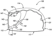
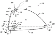
A golf club head is disclosed herein that includes a body. The body defines an internal cavity. The body also includes a sole portion positioned at a sole area of the golf club head. The bottom portion has a bottom surface area. The body also includes a crown portion positioned at a top region of the golf club head. The crown portion has a crown surface area. The body further comprises a skirt (skirt) portion, a front portion (fo)A rward) area, a rear (rearward) area opposite the front area, a heel (heel) area, and a toe (toe) area opposite the heel area, wherein the skirt portion is positioned around a periphery of the golf club head between the sole portion and the crown portion. The golf club head also includes a face portion coupled to the body at a front region of the body. The face portion includes a striking face and an inner surface opposite the striking face. The golf club head also includes a stiffener located within the interior cavity of the body and in direct contact with the interior surface of the face portion. The stiffener is made of a material having a hardness of at least shore 5.95D. An areal weight of the crown portion of the golf club head less than about 0.35g/cm over more than about 50% of a surface area of the entire surface area of the crown portion 2 . The golf club head has a Center of Gravity (CG) having x-axis coordinates of a head center plane origin between about-5 mm and about 5mm, y-axis coordinates of a head center plane origin between about 25mm and about 50mm, and z-axis coordinates of a head center plane origin less than 2 mm. The striking face has the following central regions: the central region is defined by a rectangular region of forty millimeters by twenty millimeters centered on the center of the striking face and elongated in the heel-to-toe direction. The face portion has a varying thickness. In the central region, the face portion has a maximum face thickness of not more than 4.5mm and a minimum face thickness of not less than 2.0 mm. Within the central region, the strike face has a Characteristic Time (CT) of no more than 257 microseconds. In the central region, not less than 25% of the striking face has a coefficient of restitution (COR) of at least 0.8. In the central region, no less than 60% of the strike faces have a CT of at least 235 microseconds. In the central region, no less than 35% of the strike face has a CT of at least 240 microseconds. The golf club head has a length of between about 350cm 3 And about 500cm 3 The volume in between, the moment of inertia (Izz) to the z-axis of the head's center of gravity, and the moment of inertia (Ixx) to the x-axis of the head's center of gravity. The sum of Izz and Ixx is between about 740kg mm 2 And about 1100kg mm 2 In the meantime. The foregoing subject matter of this paragraph has the features of example 1 of the present disclosure.
More than 20% of the strike faces have a CT of at least 245 microseconds. The foregoing subject matter of this paragraph has the features of example 2 of the present disclosure, wherein example 2 further includes the subject matter according to example 1 above.
In the central region, not less than 50% of the striking face has a COR of at least 0.8. The foregoing subject matter of this paragraph has features of example 3 of the present disclosure, wherein example 3 further includes the subject matter according to any of examples 1-2 above.
In the central region, not less than 55% of the striking face has a COR of at least 0.8. The foregoing subject matter of this paragraph has the features of example 4 of the present disclosure, wherein example 4 further includes the subject matter according to example 3 above.
In the central region, not less than 68% of the striking face has a COR of at least 0.8. The foregoing subject matter of this paragraph features example 5 of the present disclosure, wherein example 5 further includes the subject matter according to example 4 above.
At least a portion of the crown portion is made of a non-metallic composite material. The foregoing subject matter of this paragraph has the features of example 6 of the present disclosure, wherein example 6 further includes the subject matter according to any of examples 1 to 5 above.
The crown portion is made of a metal alloy. The foregoing subject matter of this paragraph has the features of example 7 of the present disclosure, wherein example 7 further includes the subject matter according to any of examples 1-6 above.
An areal weight of the sole portion of the golf club head less than about 0.35g/cm over more than about 50% of a surface area of the entire surface area of the sole portion 2 . The foregoing subject matter of this paragraph has the features of example 8 of the present disclosure, wherein example 8 further includes the subject matter according to any of examples 1-7 above.
The body and face portion form a one-piece, unitary structure. The foregoing subject matter of this paragraph has the features of example 9 of the present disclosure, wherein example 9 further includes the subject matter according to any of examples 1 to 8 above.
The face portion includes a face opening and a striking plate welded to the face opening. The foregoing subject matter of this paragraph has the features of example 10 of the present disclosure, wherein example 10 further includes the subject matter according to any of examples 1 to 9 above.
The sum of Izz and Ixx is greater than about 790 kg-mm 2 . The foregoing subject matter of this paragraph has features of example 11 of the present disclosure, where example 11 further includes subject matter according to any of examples 1 to 10 above.
The sum of Izz and Ixx is greater than about 805 kg-mm 2 . The foregoing subject matter of this paragraph has the features of example 12 of the present disclosure, wherein example 12 further includes the subject matter according to any of examples 1-11 above.
Ixx is not less than 305kg · mm 2 . The foregoing subject matter of this paragraph has the features of example 13 of the present disclosure, wherein example 13 further includes the subject matter according to any of examples 1-12 above.
Ixx is not less than 320 kg-mm 2 . The foregoing subject matter of this paragraph has the features of example 14 of the present disclosure, wherein example 14 further includes the subject matter according to any of examples 1-13 above.
Ixx is not less than 350kg mm 2 . The foregoing subject matter of this paragraph has the features of example 15 of the present disclosure, wherein example 15 further includes the subject matter according to any of examples 1-14 above.
In the central region, at least 60% of the strike faces have a CT of at least 240 microseconds. The foregoing subject matter of this paragraph has the features of example 16 of the present disclosure, wherein example 16 further includes the subject matter according to any of the examples 1-15 above.
At least 70% of the strike faces have a CT of at least 240 microseconds in the central region. The foregoing subject matter of this paragraph has the features of example 17 of the present disclosure, where example 17 further includes the subject matter according to example 16 above.
In the central region, at least 40% of the strike faces have a CT of at least 245 microseconds. The foregoing subject matter of this paragraph has the features of example 18 of the present disclosure, wherein example 18 further includes the subject matter according to any of the above examples 1-17.
In the central region, at least 50% of the strike faces have a CT of at least 245 microseconds. The foregoing subject matter of this paragraph has the features of example 19 of the present disclosure, where example 19 further includes the subject matter according to example 18 above.
At least 10% of the strike faces have a CT of at least 250 microseconds in the central region. The foregoing subject matter of this paragraph has the features of example 20 of the present disclosure, where example 20 further includes the subject matter according to any of the above examples 1-19.
At least 15% of the strike face has a CT of at least 250 microseconds in the central region. The foregoing subject matter of this paragraph has the features of example 21 of the present disclosure, where example 21 further includes the subject matter according to example 20 above.
The CT on the striking face at any location within at least five millimeters from the center of the striking face is greater than 240 microseconds. The foregoing subject matter of this paragraph has the features of example 22 of the present disclosure, wherein example 22 further includes the subject matter according to any of examples 1 to 21 above.
The CT of the striking face peaks along a horizontal path on the striking face through the center of the striking face at a distance of at least 30 millimeters from the center of the striking face toward the toe. The foregoing subject matter of this paragraph has the features of example 23 of the present disclosure, wherein example 23 further includes the subject matter according to any of examples 1-22 above.
The face portion also includes an aperture extending through the face portion from the striking face to the inner surface, and a plug fixedly retained in the aperture in an immovable manner. The plug protrudes from the striking face by no more than 0.15 mm or is recessed below the surface of the striking face by no more than 0.1 mm. The foregoing subject matter of this paragraph has the features of example 24 of the present disclosure, wherein example 24 further includes the subject matter according to any of examples 1-23 above.
The opening includes internal threads. The plug includes external threads threadably engaged with the internal threads of the bore. The foregoing subject matter of this paragraph has the features of example 25 of the present disclosure, where example 25 further includes the subject matter according to example 24 above.
The opening further includes a counterbore disposed between the internal threads and the striking face. The plug includes a head portion nestably engageable with the counterbore. The foregoing subject matter of this paragraph features example 26 of the present disclosure, wherein example 26 further includes the subject matter according to example 25 above.
The plug includes a portion of the stiffener. The foregoing subject matter of this paragraph has features of example 27 of the present disclosure, wherein example 27 further includes the subject matter according to any of examples 24 to 26 above.
The plug comprises a polymer material. The foregoing subject matter of this paragraph has features of example 28 of the present disclosure, wherein example 28 further includes subject matter according to any of examples 24 to 26 above.
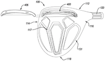
A golf club head is also disclosed herein. The golf club head includes a body defining an interior cavity and including a sole portion positioned at a sole area of the golf club head. The bottom portion has a bottom surface area. The body also includes a crown portion positioned at a top region of the golf club head. The crown portion has a crown surface area. The body also includes a skirt portion positioned around a periphery of the golf club head between the sole portion and the crown portion. The body also includes a front region, a rear region opposite the front region, a heel region, and a toe region opposite the heel region. The golf club head also includes a face portion coupled to the body at a front region of the body. The face portion includes a striking face and an inner surface opposite the striking face. The golf club head also includes a plurality of stiffeners located within the interior cavity of the body and in direct contact with the interior surface of the face portion. The plurality of stiffeners are a plurality of ribs made of the same material as the body. The face portion has a varying thickness. The maximum thickness of the face portion is no greater than 5mm, and the minimum thickness of the face portion is less than 3mm. An areal weight of the crown portion of the golf club head less than about 0.35g/cm over more than about 50% of a surface area of the entire surface area of the crown portion 2 . An areal weight of the sole portion of the golf club head less than about 0.35 g/cm over more than about 50% of a surface area of the entire surface area of the sole portion 2 . The striking face has the following central regions: the central region is formed by a length of forty millimeters by two in the heel-to-toe direction centered at the center of the striking faceA rectangular area of ten millimeters. Within the central region, the strike face has a Characteristic Time (CT) of no more than 257 microseconds. In the central region, not less than 25% of the striking face has a coefficient of restitution (COR) of at least 0.8. In the central region, not less than 60% of the strike face has a CT of at least 235 microseconds. In the central region, not less than 35% of the strike faces have a CT of at least 240 microseconds. The foregoing subject matter of this paragraph features example 29 of the present disclosure.
The plurality of ribs is located proximate a transition between the face portion and the crown portion. The foregoing subject matter of this paragraph features example 30 of the present disclosure, wherein example 30 further includes the subject matter according to example 29 above.
The plurality of ribs is located proximate a transition between the face portion and the base portion. The foregoing subject matter of this paragraph has the features of example 31 of the present disclosure, wherein example 31 further includes the subject matter according to any of examples 29 to 30 above.
The body and face portion form a one-piece, unitary structure. The foregoing subject matter of this paragraph has features of example 32 of the present disclosure, wherein example 32 further includes the subject matter according to any of examples 29 to 31 above.
The face portion includes a face opening and a striking plate welded to the face opening. The foregoing subject matter of this paragraph has features of example 33 of the present disclosure, wherein example 33 further includes the subject matter according to any of examples 29 to 31 above.
At least one of the plurality of ribs has a head origin x-axis coordinate of between +15mm and +25mm, and at least one of the plurality of ribs has a head origin x-axis coordinate of between-15 mm and-25 mm. The foregoing subject matter of this paragraph has the features of example 34 of the present disclosure, wherein example 34 further includes the subject matter according to any of examples 29 to 33 above.
Further disclosed herein is a golf club head comprising a body. The body defines an interior cavity, and the body includes a sole portion positioned at a sole area of the golf club head. The bottom portion has a bottom surface area. The body is also provided withIncluding a crown portion positioned at a top region of the golf club head. The crown portion has a crown surface area. The body further includes a skirt portion, a front region, a rear region opposite the front region, a heel region, and a toe region opposite the heel region, wherein the skirt portion is positioned around a perimeter of the golf club head between the sole portion and the crown portion. The body also includes a face portion coupled to the body at a front region of the body. The face portion includes a striking face and an inner surface opposite the striking face. The body further includes a plurality of stiffeners located within the interior cavity of the body and offset from the interior surface of the face portion by at least 1mm and no more than 20 mm as measured along the head origin y-axis. The plurality of stiffeners are elongated stiffening members extending between the inner surface of the crown portion and the inner surface of the sole portion. The face portion has a varying thickness. The maximum thickness of the face portion is not greater than 5mm, and the minimum thickness of the face portion is less than 3mm. An areal weight of the crown portion of the golf club head less than about 0.35g/cm over more than about 50% of a surface area of the entire surface area of the crown portion 2 . An areal weight of the sole portion of the golf club head less than about 0.35g/cm over more than about 50% of a total surface area of the sole portion 2 . The striking face has the following central region: the central region is defined by a rectangular area of forty millimeters by twenty millimeters centered on the center of the striking face and elongated in the heel-to-toe direction. Within the central region, the striking face has a Characteristic Time (CT) of no more than 257 microseconds. In the central region, not less than 25% of the striking surfaces have a coefficient of restitution (COR) of at least 0.8. In the central region, not less than 60% of the strike face has a CT of at least 235 microseconds. In the central region, no less than 35% of the strike face has a CT of at least 240 microseconds. The foregoing subject matter of this paragraph features example 35 of the present disclosure.
The body and face portion form a one-piece, unitary structure. The foregoing subject matter of this paragraph features example 36 of the present disclosure, wherein example 36 further includes the subject matter according to example 35 above.
The face portion includes a face opening and a striking plate welded to the face opening. The foregoing subject matter of this paragraph has features of example 37 of the present disclosure, wherein example 37 further includes the subject matter according to example 35 above.
In the central region, the thickness of the face portion near the center of the striking face is greatest. The foregoing subject matter of this paragraph has the features of example 38 of the present disclosure, wherein example 38 further includes the subject matter according to any of examples 35 to 37 above.
The thickness of the face portion at the center of the striking face is greater than 2.9mm. The foregoing subject matter of this paragraph has the features of example 39 of the present disclosure, wherein example 39 further includes the subject matter according to any of examples 35 to 38 above.
The plurality of stiffeners includes two or more support rods. The two or more support rods each have a mass per unit length (mass per unit length) of between 0.005g/mm and 0.40 g/mm. The foregoing subject matter of this paragraph has the features of example 40 of the present disclosure, wherein example 40 further includes the subject matter according to any of examples 35 to 39 above.
The body also includes a channel. The golf club head also includes one or more polymer reinforcements positioned within the channel, and the body also includes a channel. The golf club head also includes one or more polymer stiffeners located within the channels. The foregoing subject matter of this paragraph has the features of example 41 of the present disclosure, wherein example 41 further includes the subject matter according to any of examples 35 to 40 above.
At least one stiffener of the plurality of stiffeners has a head origin x-axis coordinate between +15mm and +25mm, and at least one stiffener of the plurality of stiffeners has a head origin x-axis coordinate between-15 mm and-25 mm. The foregoing subject matter of this paragraph has the features of example 42 of the present disclosure, wherein example 42 further includes the subject matter according to any of examples 35 to 41 above.
Also disclosed herein is a golf club head comprising a body. The body defines an interior cavity and includes a bottom portionThe sole portion is positioned at a sole area of the golf club head, the sole portion having a sole surface area. The body also defines a crown portion positioned at a top region of the golf club head, the crown portion having a crown surface area. The body also defines a skirt portion positioned around a periphery of the golf club head between the sole portion and the crown portion. The body further defines a front region, a rear region opposite the front region, a heel region, and a toe region opposite the heel region. The golf club head also includes a face portion coupled to the body at a front region of the body, and the face portion includes a striking face and an inner surface opposite the striking face. The face portion has a varying thickness. An areal weight of the crown portion of the golf club head less than about 0.35g/cm over more than about 50% of a surface area of the entire surface area of the crown portion 2 . An areal weight of the sole portion of the golf club head less than about 0.35g/cm over more than about 50% of a surface area of the entire surface area of the sole portion 2 . The striking face has the following central regions: the central region is defined by a rectangular area of forty millimeters by twenty millimeters centered on the center of the striking face and elongated in the heel-to-toe direction. In the central region, the maximum thickness of the face portion is not more than 4mm, and the minimum thickness of the face portion is not less than 2.4mm. Within the central region, the strike face has a Characteristic Time (CT) of no more than 257 microseconds. In the central region, not less than 25% of the striking face has a coefficient of restitution (COR) of at least 0.8.
In the central region, no less than 60% of the strike faces have a CT of at least 235 microseconds. In the central region, no less than 50% of the strike faces have a CT of at least 240 microseconds. The foregoing subject matter of this paragraph has features of example 43 of the present disclosure.
The body and the face portion form a one-piece, unitary structure. The foregoing subject matter of this paragraph features example 44 of the present disclosure, wherein example 44 further includes the subject matter according to example 43 above.
The face portion includes a face opening and a striking plate welded to the face opening. The foregoing subject matter of this paragraph has features of example 45 of the present disclosure, wherein example 45 further includes the subject matter according to example 43 above.
In the central region, the thickness of the face portion near the center of the striking face is greatest. The foregoing subject matter of this paragraph has the features of example 46 of the present disclosure, wherein example 46 further includes the subject matter according to any of examples 43 to 45 above.
The thickness of the face portion at the center of the striking face is greater than 2.9mm. The foregoing subject matter of this paragraph has the features of example 47 of the present disclosure, wherein example 47 further includes the subject matter according to any of examples 43 to 46 above.
In the central region, not less than 15% of the strike face has a CT of at least 245 microseconds. The foregoing subject matter of this paragraph has the features of example 48 of the present disclosure, wherein example 48 further includes the subject matter according to any of examples 43 to 47 above.
The sole portion, crown portion and skirt portion of the body form a one-piece, unitary structure, and wherein the face portion includes a face opening and a striking plate closing the face opening. The foregoing subject matter of this paragraph has the features of example 49 of the present disclosure, wherein example 49 further includes the subject matter according to any of examples 43-48 above.
The face portion includes a face opening and a striking plate welded to the face opening. The foregoing subject matter of this paragraph has features of example 50 of the present disclosure, wherein example 50 further includes subject matter according to any of examples 43 and 45-49 above.
The face portion includes a face opening and a striking plate bonded or adhered to the face opening. The foregoing subject matter of this paragraph has features of example 51 of the present disclosure, wherein example 51 further includes subject matter according to any of example 43 and examples 45-49 above.
The body and face portion form a one-piece, unitary structure. The crown portion includes a crown opening and a crown insert closing the crown opening. The crown insert is formed of a material having a lower density than the face portion and the remainder of the body. The foregoing subject matter of this paragraph has features of example 52 of the present disclosure, wherein example 52 further includes the subject matter according to any of examples 43, 44, and examples 46-49 above.
The golf club head also includes two or more support rods extending from the inner surface of the sole portion to the inner surface of the crown portion, wherein each support rod of the two or more support rods has a mass per unit length of between 0.005g/mm and 0.40 g/mm. The foregoing subject matter of this paragraph has the features of example 53 of the present disclosure, wherein example 53 further includes the subject matter according to any of examples 43 to 52 above.
Wherein the two or more support rods are formed of the same material as the body. The foregoing subject matter of this paragraph features example 54 of this disclosure, wherein example 54 further includes the subject matter according to example 53 above.
The two or more support rods are formed of a material having a density lower than that of the body. The foregoing subject matter of this paragraph has the features of example 55 of the present disclosure, wherein example 55 further includes the subject matter according to any of examples 53-54 above.
The two or more support rods have head origin y-axis coordinates between head origin y-axis coordinates of a center of gravity of the golf club head and head origin y-axis coordinates of the face portion of the golf club head. The foregoing subject matter of this paragraph has the features of example 56 of the present disclosure, wherein example 56 further includes the subject matter according to any of examples 53-55 above.
The two or more support rods are positioned between 1mm and 20mm, including 1mm and 20mm, from the face portion. The foregoing subject matter of this paragraph has features of example 57 of the present disclosure, wherein example 57 further includes subject matter according to any of examples 53-56 above.
The two or more support rods are positioned at least 20mm forward from the center of gravity of the golf club head as measured along the y-axis of the club head origin. The foregoing subject matter of this paragraph has the features of example 58 of the present disclosure, wherein example 58 further includes the subject matter according to any of examples 53-57 above.
Within the central region, the ratio of the thickness of the thinnest portion of the face portion to the thickness of the thickest portion of the face portion is between 0.60 and 1.0, including 0.60 and 1.0. The foregoing subject matter of this paragraph has the features of example 59 of the present disclosure, wherein example 59 further includes the subject matter according to any of examples 53-58 above.
Within the central region, the ratio of the thickness of the thinnest portion of the face portion to the thickness of the thickest portion of the face portion is between 0.70 and 1.0, including 0.70 and 1.0. The foregoing subject matter of this paragraph has features of example 60 of the present disclosure, wherein example 60 further includes the subject matter according to any of examples 53-59 above.
In the central region, not less than 50% of the striking face has a COR of at least 0.8. The foregoing subject matter of this paragraph features example 61 of the present disclosure, wherein example 61 further includes the subject matter according to any of examples 53-60 above.
A golf club head is described herein that includes a body and a face portion. The body defines an interior cavity, and the body includes a bottom portion positioned at a bottom area of the golf club head, a crown portion positioned at a top area of the golf club head, a skirt portion positioned between the bottom portion and the crown portion around a periphery of the golf club head, a front area, a rear area opposite the front area, a heel area, and a toe area opposite the heel area. The face portion is coupled to the body at a front region of the body, and the face portion includes a striking plate. The golf club head also includes at least one stiffener that includes at least one rib located within the interior cavity and directly coupled to the face portion at a location of the club head origin coordinate system of the golf club head that has an x-axis coordinate greater than 20mm and less than 50mm or greater than-50 mm and less than-20 mm. A ratio of a height of the at least one rib to a height of the face portion is greater than or equal to 0.15. The foregoing subject matter of this paragraph features example 62 of the present disclosure.
A ratio of a height of the at least one rib to a height of the face portion is greater than or equal to 0.20. The foregoing subject matter of this paragraph has features of example 63 of the present disclosure, wherein example 63 further includes the subject matter according to example 62 above.
A ratio of a height of the at least one rib to a height of the face portion is greater than or equal to 0.25. The foregoing subject matter of this paragraph features example 64 of the present disclosure, wherein example 64 further includes the subject matter according to example 63 above.
The at least one rib is directly coupled to the face portion at the bottom region. The at least one stiffener further includes at least one rib coupled directly to the face portion at the top region. A ratio of a sum of a height of the at least one rib directly coupled to the face portion at the bottom region and a height of the at least one rib directly coupled to the face portion at the top region to the height of the face portion is greater than or equal to 0.3. The foregoing subject matter of this paragraph has the features of example 65 of the present disclosure, wherein example 65 further includes the subject matter according to any of examples 62 to 64 above.
A ratio of a sum of a height of the at least one rib directly coupled to the face portion at the bottom region and a height of the at least one rib directly coupled to the face portion at the top region to the height of the face portion is greater than or equal to 0.4. The foregoing subject matter of this paragraph features example 66 of the present disclosure, wherein example 66 further includes the subject matter according to example 65 above.
The at least one rib is directly coupled to the face portion at a location of a club head origin coordinate system of the golf club head having an x-axis coordinate greater than 30mm and less than 40mm or greater than-40 mm and less than-30 mm. The foregoing subject matter of this paragraph has features of example 67 of the present disclosure, wherein example 67 further includes the subject matter according to any of examples 62 to 66 above.
The at least one stiffener includes at least two ribs. One of the at least two ribs is directly coupled to the face portion at the sole region at a location of a club head origin coordinate system of the golf club head having an x-axis coordinate greater than 30mm and less than 40 mm. Another of the at least two ribs is directly coupled to the face portion at the sole region at a location of a club head origin coordinate system of the golf club head having an x-axis coordinate greater than 40mm and less than 50 mm. The foregoing subject matter of this paragraph has the features of example 68 of the present disclosure, wherein example 68 further includes the subject matter according to any of examples 62 to 67 above.
A ratio of a height of one of the at least two ribs directly coupled to the face portion at the sole region at a location of a club head origin coordinate system of the golf club head having an x-axis coordinate greater than 30mm and less than 40mm to a height of the face portion is 0.17. A ratio of a height of another of the at least two ribs directly coupled to the face portion at the sole region at a location of a club head origin coordinate system of the golf club head having an x-axis coordinate greater than 40mm and less than 50mm to a height of the face portion is 0.23. The foregoing subject matter of this paragraph features example 69 of the present disclosure, wherein example 69 further includes the subject matter according to example 68 above.
The at least one stiffener includes at least two ribs. A first rib of the at least two ribs is located at a position of the club head origin coordinate system of the golf club head having an x-axis coordinate greater than 20mm and less than 50 mm. A second rib of the at least two ribs is located at a position of a club head origin coordinate system of the golf club head having an x-axis coordinate greater than-50 mm and less than-20 mm. The foregoing subject matter of this paragraph has features of example 70 of the present disclosure, wherein example 70 further includes the subject matter according to any of examples 62 to 69 above.
The at least one stiffener includes at least two ribs. The at least two ribs are located at a position of a club head origin coordinate system of the golf club head having an x-axis coordinate greater than 20mm and less than 50 mm. The foregoing subject matter of this paragraph has features of example 71 of the present disclosure, wherein example 71 further includes the subject matter according to any of examples 62 to 70 above.
One of the at least two ribs is directly coupled to the face portion at the top region at a location of a club head origin coordinate system of the golf club head having an x-axis coordinate greater than 30mm and less than 40 mm. Another of the at least two ribs is directly coupled to the face portion at the top region at a location of a club head origin coordinate system of the golf club head having an x-axis coordinate greater than 40mm and less than 50 mm. The foregoing subject matter of this paragraph is featured by example 72 of the present disclosure, wherein example 72 further includes the subject matter according to example 71 above.
The at least one rib is coupled directly to the face portion at a top area of the golf club head. The foregoing subject matter of this paragraph has features of example 73 of the present disclosure, wherein example 73 further includes the subject matter according to any of examples 62 to 72 above.
The at least one rib is coupled directly to the face portion at a sole region of the golf club head. The foregoing subject matter of this paragraph has features of example 74 of the present disclosure, wherein example 74 further includes the subject matter according to any of examples 62 to 73 above.
The height of the at least one rib decreases only in a direction from the front region to the rear region. The foregoing subject matter of this paragraph has the features of example 75 of the present disclosure, wherein example 75 further includes the subject matter according to any of examples 62 to 74 above.
The golf club head also includes a slot formed in the sole portion and extending lengthwise from the heel region to the toe region. The at least one rib is coupled to the slot and is disposed between the slot and the face portion. The foregoing subject matter of this paragraph has features of example 76 of the present disclosure, wherein example 76 further includes the subject matter according to any of examples 62 to 75 above.
The body includes an outer wall. The golf club head further includes at least one aperture formed in an exterior wall of the body and opening directly into the at least one rib. The foregoing subject matter of this paragraph has features of example 77 of the present disclosure, wherein example 77 further includes subject matter according to any of examples 1-76 above.
The at least one rib is directly coupled to the striking plate of the face portion. The foregoing subject matter of this paragraph has features of example 78 of the present disclosure, wherein example 78 further includes the subject matter according to any of examples 62 to 77 above.
The at least one rib is directly coupled to the face portion along an entire height of the at least one rib. The foregoing subject matter of this paragraph has features of example 79 of the present disclosure, wherein example 79 further includes subject matter according to any of examples 62-78 above.
A golf club head is further described herein. The golf club head includes a body and a face portion. The body defines an interior cavity, and the body includes a bottom portion positioned at a bottom region of the golf club head, a crown portion positioned at a top region of the golf club head, a skirt portion positioned between the bottom portion and the crown portion around a periphery of the golf club head, a front region, a rear region opposite the front region, a heel region, and a toe region opposite the heel region. The golf club head also includes a face portion coupled to the body at a front region of the body, and the face portion includes a striking plate. The golf club head also includes at least one stiffening element comprising a discrete mass (discrete mass) of polymer material located within the interior cavity and directly coupled to the face portion at a location of a club head origin coordinate system of the golf club head having an x-axis coordinate greater than 20mm and less than 50mm or greater than-50 mm and less than-20 mm. The polymeric material of the at least one discrete block has a hardness equal to or greater than about shore 10D. The foregoing subject matter of this paragraph features example 80 of the present disclosure.
The polymeric material has a hardness equal to or greater than about shore 20D. The foregoing subject matter of this paragraph has the features of example 81 of the present disclosure, wherein example 81 further comprises the subject matter according to example 80 above.
The polymeric material has a hardness equal to or greater than about shore 45D. The foregoing subject matter of this paragraph has the features of example 82 of the present disclosure, where example 82 further includes the subject matter according to example 81 above.
The polymeric material has a hardness equal to or greater than about shore 85D. The foregoing subject matter of this paragraph has the features of example 83 of the present disclosure, where example 83 further includes the subject matter according to example 82 above.
The polymeric material is acrylic. The foregoing subject matter of this paragraph has features of example 84 of the present disclosure, wherein example 84 further includes the subject matter according to any of examples 80-83 above.
The polymeric material is a thermoset material. The foregoing subject matter of this paragraph has features of example 85 of the present disclosure, wherein example 85 further includes the subject matter according to any of examples 80-84 above.
The polymeric material is a thermoplastic material. The foregoing subject matter of this paragraph features example 86 of the present disclosure, wherein example 86 further includes the subject matter according to any of examples 80-85 above.
The golf club head also includes a retaining wall coupled to the sole portion, projecting vertically from the sole portion, and extending lengthwise in a heel-to-toe direction. A discrete piece of polymeric material is coupled to the retaining wall and is disposed between the retaining wall and the face portion. The foregoing subject matter of this paragraph has features of example 87 of the present disclosure, wherein example 87 further includes the subject matter according to any of examples 80-86 above.
The golf club head also includes a slot formed in the sole portion and extending lengthwise from the heel region to the toe region. The retaining wall forms a portion of the trough. The foregoing subject matter of this paragraph features example 88 of the present disclosure, wherein example 88 further includes the subject matter according to example 87 above.
The retaining wall projects further away from the bottom portion than the slot. The foregoing subject matter of this paragraph has features of example 89 of the present disclosure, where example 89 further includes the subject matter according to example 88 above.
The at least one stiffener further comprises foam. Discrete pieces of polymeric material are supported on the foam. The foam is coupled to the trough and disposed between the trough and the face portion. The foam is disposed between the discrete pieces of polymeric material and the bottom portion. The foregoing subject matter of this paragraph has features of example 90 of the present disclosure, wherein example 90 further includes the subject matter according to any of examples 88-89 above.
The at least one stiffener further includes an enclosure made of foam and coupled to the face portion. The enclosure defines the following cavities: the cavity receives and laterally confines the discrete pieces of polymeric material. The cavity is open towards the face portion. The foregoing subject matter of this paragraph has the features of example 91 of the present disclosure, wherein example 91 further includes the subject matter according to any of examples 80-90 above.
The golf club head also includes a plurality of stiffeners. The enclosures of the plurality of stiffeners are spaced apart from one another. The foregoing subject matter of this paragraph features example 92 of the present disclosure, wherein example 92 further includes the subject matter according to example 91 above.
The golf club head also includes a plurality of stiffeners. The enclosures of the plurality of stiffeners form a one-piece, unitary structure. The foregoing subject matter of this paragraph features example 93 of the present disclosure, where example 93 further includes subject matter according to example 91 above.
The body includes an outer wall. The golf club head also includes at least one aperture formed in an outer wall of one of the body or the face portion and opening directly into the discrete pieces of polymeric material. The foregoing subject matter of this paragraph has features of example 94 of the present disclosure, wherein example 94 further includes the subject matter according to any of examples 80-93 above.
The at least one aperture is formed in an outer wall of the face portion. The foregoing subject matter of this paragraph features example 95 of the present disclosure, wherein example 95 further includes the subject matter according to example 94 above.
The golf club head further includes a plurality of stiffening elements, and at least one of the discrete pieces has a different amount of polymeric material than another of the discrete pieces, or has a different type of polymeric material than another of the discrete pieces. The foregoing subject matter of this paragraph has features of example 96 of the present disclosure, wherein example 96 further includes subject matter according to any of examples 80 to 95 above.
The discrete pieces of polymeric material are directly coupled to the striking plate of the face portion. The foregoing subject matter of this paragraph features example 97 of the present disclosure, wherein example 97 further includes subject matter according to any of examples 80-96 above.
The discrete pieces of polymeric material are directly coupled to the face portion at a location at least 5mm away from the peripheral edge of the face portion. The foregoing subject matter of this paragraph has features of example 98 of the present disclosure, wherein example 98 further includes subject matter according to any of examples 80 to 97 above.
The discrete pieces of polymeric material are directly coupled to the face portion at a location at least 15mm away from the peripheral edge of the face portion. The foregoing subject matter of this paragraph has features of example 99 of the present disclosure, wherein example 99 further includes the subject matter according to example 98 above.
At least 50mm of the discrete pieces of polymeric material and the face portion 2 Are in contact. The foregoing subject matter of this paragraph has features of example 100 of the present disclosure, wherein example 100 further includes subject matter according to any of examples 80 to 99 above.
At least 150mm of discrete patches of polymeric material to the face portion 2 Are in contact. The foregoing subject matter of this paragraph has features of example 101 of the present disclosure, where example 101 further includes subject matter according to example 100 above.
At least 225mm of discrete pieces of polymeric material and face portion 2 Are in contact. The foregoing subject matter of this paragraph has features of example 102 of the present disclosure, wherein example 102 further includes the subject matter according to example 101 above.
The golf club head also includes a plurality of stiffeners. The discrete pieces of polymeric material of one of the plurality of stiffeners are in contact with the surface area of the face portion in an amount that is different than an amount that the discrete pieces of polymeric material of another of the plurality of stiffeners are in contact with the surface area of the face portion. The foregoing subject matter of this paragraph has features of example 103 of the present disclosure, wherein example 103 further includes subject matter according to any of examples 80 to 102 above.
Golf club headA plurality of stiffeners is also included. The discrete pieces of polymeric material of the plurality of stiffeners together with at least 100mm of the face portion 2 Are in contact. The foregoing subject matter of this paragraph has features of example 104 of the present disclosure, wherein example 104 further includes subject matter according to any of examples 80 to 103 above.
The discrete pieces of polymeric material of the plurality of stiffeners collectively are at least 800 mm of the face portion 2 Are in contact. The foregoing subject matter of this paragraph has features of example 105 of the present disclosure, wherein example 105 further includes subject matter according to example 104 above.
Discrete pieces of polymeric material are in contact with the surface area of the face portion. The ratio of the surface area of the face portion that the discrete pieces of polymeric material contact to the total interior surface area of the face portion is at least 0.01. The foregoing subject matter of this paragraph has features of example 106 of the present disclosure, wherein example 106 further includes subject matter according to any of examples 80 to 105 above.
The ratio of the surface area of the face portion that is contacted by the discrete pieces of polymeric material to the total interior surface area of the face portion is at least 0.05. The foregoing subject matter of this paragraph features example 107 of the present disclosure, wherein example 107 further includes the subject matter according to example 106 above.
The ratio of the surface area of the face portion that the discrete pieces of polymeric material contact to the total interior surface area of the face portion is at least 0.1. The foregoing subject matter of this paragraph has features of example 108 of the present disclosure, wherein example 108 further includes the subject matter according to example 107 above.
The at least one stiffener further comprises foam. Discrete pieces of polymeric material are supported on the foam. Discrete pieces of foam and polymer material are located at a sole region of the golf club head. The golf club head further includes at least one additional armature including a rib coupled directly to the face portion at a top region of the golf club head. The ratio of the height of the ribs to the height of the face portion is greater than or equal to 0.15. The foregoing subject matter of this paragraph has features of example 109 of the present disclosure, wherein example 109 further includes the subject matter according to any of examples 80-108 above.
Also disclosed herein is a golf club head comprising a body and a face portion. The body defines an interior cavity, and the body includes a bottom portion positioned at a bottom area of the golf club head, a crown portion positioned at a top area of the golf club head, a skirt portion positioned between the bottom portion and the crown portion around a periphery of the golf club head, a front area, a rear area opposite the front area, a heel area, and a toe area opposite the heel area. The face portion is coupled to the body at a front region of the body, and the face portion includes a striking plate. The golf club head also includes at least one armature including a foam and a discrete piece of polymer material supported on the foam, the foam and the discrete piece being located within the interior cavity, the discrete piece being directly coupled to the face portion. The foregoing subject matter of this paragraph features example 110 of the present disclosure.
A golf club head is also described herein that includes a body and a face portion. The body defines an interior cavity, and the body includes a sole portion positioned at a sole region of the golf club head, a crown portion positioned at a top region of the golf club head, a skirt portion positioned between the sole portion and the crown portion about a periphery of the golf club head, a front region, a rear region opposite the front region, a heel region, and a toe region opposite the heel region. The golf club head also includes a face portion coupled to the body at a front region of the body, and the face portion includes a striking plate. The golf club head further includes at least one armature including a fastener at least partially located within the interior cavity and adjustably coupled to the body. The fastener is adjustable to reinforce the face portion. The foregoing subject matter of this paragraph features example 111 of the present disclosure.
The entire fastener is located in the interior cavity. The foregoing subject matter of this paragraph has the features of example 112 of the present disclosure, wherein example 112 further comprises the subject matter according to example 111 above.
The golf club head includes a port formed in the body. The fastener is accessible via the port by means of a tool. The foregoing subject matter of this paragraph has features of example 113 of the present disclosure, wherein example 113 further includes subject matter according to any of examples 111-112 above.
The fastener includes an end surface. The fastener is adjustable to bring the face portion into contact with the end surface of the fastener. The end surface is rounded. The foregoing subject matter of this paragraph has the features of example 114 of the present disclosure, wherein example 114 further comprises the subject matter according to any of examples 111-113 above.
The at least one stiffener further includes a fastener rib. The fastener rib includes a threaded aperture. The fastener extends through and threadably engages the threaded aperture of the fastener rib. The foregoing subject matter of this paragraph has features of example 115 of the present disclosure, wherein example 115 further includes the subject matter according to any of examples 111-114 above.
The at least one stiffener further includes a spring element and a washer, wherein the spring element includes an aperture and the washer includes an aperture. The spring element is disposed between the fastener rib and the washer. The fastener extends through the aperture of the spring element and the aperture of the washer. The foregoing subject matter of this paragraph features example 116 of the present disclosure, wherein example 116 further includes subject matter according to example 115 above.
The spring element is made of a polymer material. The foregoing subject matter of this paragraph has features of example 117 of the present disclosure, wherein example 117 further includes subject matter according to example 116 above.
The golf club head includes a threaded port formed in the body. The fastener is threadably engaged with the threaded port. The foregoing subject matter of this paragraph has the features of example 118 of the present disclosure, wherein example 118 further includes the subject matter according to any of examples 111-117 above.
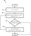
Also disclosed herein is a method of adjusting a Characteristic Time (CT) of a golf club head after the golf club head is produced. The method comprises the following steps: at least one stiffener is adjusted, the at least one stiffener located at least partially within the interior cavity of the golf club head and directly coupleable to the face portion of the golf club head. Adjusting the at least one stiffener comprises at least one of: removing material from the at least one stiffener via an aperture in a golf club head, the at least one stiffener including a rib; adding a polymeric material to the at least one armature via a port formed in the golf club head, the polymeric material having a hardness equal to or greater than about Shore 10D; or adjusting a fastener at least partially within the interior cavity into contact with or in contact with the face portion of the golf club head. The foregoing subject matter of this paragraph features example 119 of the present disclosure.
A plurality of golf club heads are provided that each include a body and a face portion. The body defines an internal cavity. Further, the body includes a sole portion positioned at a sole region of the golf club head, a crown portion positioned at a top region of the golf club head, and a skirt portion positioned between the sole portion and the crown portion around a periphery of the golf club head, wherein an entire outer surface of the crown portion is convex. The body also includes a front region, a rear region opposite the front region, a heel region, and a toe region opposite the heel region. The face portion is coupled to the body at a front region of the body, and the face portion includes a striking plate. The Characteristic Time (CT) at the center face of the striking plate, the characteristic time at a first location on the striking plate 20 millimeters (mm) away from the center face toward the toe region, and the characteristic time at a second location on the striking plate 20mm away from the center face toward the heel region of each golf club head falls within a two microsecond standard deviation of a predetermined target CT prior to manufacturing the golf club head. The foregoing subject matter of this paragraph has features of example 120 of the present disclosure.
The target CT is between 235 microseconds and 257 microseconds. The foregoing subject matter of this paragraph features example 121 of the present disclosure, wherein example 121 further includes subject matter according to example 120 above.
The target CT is between 240 microseconds and 250 microseconds. The foregoing subject matter of this paragraph features example 122 of the present disclosure, wherein example 122 further includes subject matter according to example 121 above.
The target CT is 247 microseconds. The foregoing subject matter of this paragraph features example 123 of the present disclosure, wherein example 123 further includes the subject matter according to example 122 above.
Each golf club head includes at least one armature at least partially within the interior cavity and directly coupleable to the face portion at a discrete location. The at least one armature can be configured to selectively adjust the CT of the striking plate near the discrete locations of the face portion after manufacturing the golf club head such that the CT at the center face of the striking plate, the CT at a first location on the striking plate 20mm away from the center face toward the toe region, and the CT at a second location on the striking plate 20mm away from the center face toward the heel region fall within a standard deviation of 2 microseconds of the target CT. The foregoing subject matter of this paragraph has features of example 124 of the present disclosure, wherein example 124 further includes subject matter according to any of examples 120 to 123 above.
The entire outer surface of the crown portion is convex. The foregoing subject matter of this paragraph has features of example 125 of the present disclosure, wherein example 125 further includes subject matter according to any of examples 62 to 118 and examples 120 to 124 above.
The striking plate has a thickness of at least 3500mm 2 And a maximum height of at least about 50mm from ground level. The foregoing subject matter of this paragraph has features of example 126 of the present disclosure, wherein example 126 further includes the subject matter according to any of examples 62 to 118 and examples 120 to 125 above.
The volume of the golf club head is at least about 370cm 3 . The foregoing subject matter of this paragraph has features of example 127 of the present disclosure, wherein example 127 further comprises steps according to examples 62 to 118 andthe subject matter of any of examples 120 to 126.
The crown portion of the body is made of a first material, at least one of the sole portion or the skirt portion of the body is made of a second material different from the first material, and the crown portion is adhered to the skirt portion. The foregoing subject matter of this paragraph has features of example 128 of the present disclosure, wherein example 128 further includes subject matter according to any of examples 62 to 118 and examples 120 to 127 above.
A golf club head is disclosed herein that includes a body. The body defines an internal cavity. The body further includes a sole portion positioned at a sole region of the golf club head, a crown portion positioned at a top region of the golf club head, a skirt portion positioned between the sole portion and the crown portion around a periphery of the golf club head, a front region, a rear region opposite the front region, a heel region, and a toe region opposite the heel region. The golf club head also includes a face portion coupled to the body at a front region of the body. The face portion has a lobe radius between 190mm and 600mm and a lap radius between 100mm and 600 mm. The golf club head also includes a first wall projecting vertically from the sole portion, extending lengthwise in a heel-to-toe direction, and made of a first material having a first modulus of elasticity between 15GPa and 350 GPa. The golf club head also includes a stiffening member located within the interior cavity of the body and disposed between the interior surface of the face portion and the first wall. The stiffener is made of a second material having a second modulus of elasticity that is less than the first modulus of elasticity, the second modulus of elasticity being between 0.5GPa and 30GPa, and the second material having a hardness of at least shore 5.95D. The golf club head has a coefficient of restitution (COR) of at least 0.78. A Characteristic Time (CT) of the golf club head at a center of the face portion is not more than 257 microseconds. The foregoing subject matter of this paragraph has the features of example 129 of this disclosure.
The inner surface of the face portion includes a continuous bead around the center of the face portion. The thickness of the face portion at the continuous bead is greater than the thickness of the face portion at a portion immediately adjacent to the continuous bead. The reinforcement extends from the inner surface of the body at least to the continuous bead. The foregoing subject matter of this paragraph has features of example 130 of the present disclosure, where example 130 further includes subject matter according to example 129 above.
The reinforcement is in direct contact with the continuous bead. The foregoing subject matter of this paragraph has features of example 131 of the present disclosure, wherein example 131 further includes subject matter according to example 130 above.
The reinforcement member is in direct contact with the inner surface of the face portion. The foregoing subject matter of this paragraph has features of example 132 of the present disclosure, wherein example 132 further includes subject matter according to any of examples 129 to 131 above.
The golf club head also includes a second wall projecting vertically from the sole portion, extending lengthwise in a generally front-to-rear direction, and made of a third material having a third modulus of elasticity that is less than the first modulus of elasticity. The second elastic modulus is greater than the third elastic modulus. The stiffener abuts the second wall. The foregoing subject matter of this paragraph has features of example 133 of the present disclosure, where example 133 further includes subject matter according to any of examples 129 to 132 above.
The third elastic modulus is between 0.01GPa and 8.0 GPa. The foregoing subject matter of this paragraph has features of example 134 of the present disclosure, wherein example 134 further includes subject matter according to example 133 above.
The golf club head also includes a third wall projecting vertically from the sole portion, extending lengthwise in a generally front-to-rear direction, spaced from the second wall in a direction parallel to the heel-to-toe direction, and made of a third material. The reinforcement abuts the third wall and is disposed between the second wall and the third wall. The foregoing subject matter of this paragraph has features of example 135 of the present disclosure, wherein example 135 further includes subject matter according to any of the above examples 133-134.
The third elastic modulus is between 0.01Gpa and 8.0 GPa. The foregoing subject matter of this paragraph features example 136 of the present disclosure, wherein example 136 further includes subject matter according to example 135 above.
The second wall abuts the inner surface of the face portion and the first wall. The third wall abuts the inner surface of the face portion and the first wall. The stiffener abuts the first, second, and third walls. The foregoing subject matter of this paragraph has features of example 137 of the present disclosure, wherein example 137 further includes the subject matter according to any of examples 135-136 above.
The first material is one of titanium or steel. The second material is a foam. The third material is acrylic. The foregoing subject matter of this paragraph has features of example 138 of the present disclosure, wherein example 138 further includes the subject matter according to any of examples 135-137 above.
The first wall, the second wall, the third wall, and the reinforcement constitute a reinforcement assembly. The stiffener assembly is located at a toe or heel facing position of the center of the face portion. The foregoing subject matter of this paragraph has features of example 139 of the present disclosure, wherein example 139 further includes subject matter according to any of the above examples 135-138.
The golf club head further includes a plurality of stiffener assemblies each located at a toe or heel facing position of a center of the face portion. The foregoing subject matter of this paragraph has features of example 140 of the present disclosure, wherein example 140 further includes the subject matter according to example 139 above.
The maximum height of the stiffener is less than the maximum height of the first wall, the maximum height of the second wall, and the maximum height of the third wall. The foregoing subject matter of this paragraph has features of example 141 of the present disclosure, where example 141 further includes subject matter according to any of the above examples 135-140.
The first wall extends lengthwise in a generally heel-to-toe direction less than an entire length of an entire section of the face portion that is contiguous with the bottom portion of the body. The stiffener extends longitudinally parallel to the heel-to-toe direction less than the entire length of the entire section of the face portion adjacent the sole portion of the body. The entire length of the stiffener is no greater than the entire length of the first wall. The foregoing subject matter of this paragraph features example 142 of the present disclosure, wherein example 142 further includes subject matter according to any of examples 129 to 141 above.
The first wall and the stiffening member are positioned along a y-z plane of a club head origin coordinate system of the golf club head. The foregoing subject matter of this paragraph features example 143 of the present disclosure, wherein example 143 further includes subject matter according to example 142 above.
The golf club head also includes a slot formed in the bottom portion of the body and extending lengthwise parallel to the heel-to-toe direction. The first wall forms the forwardmost sidewall of the trough. The foregoing subject matter of this paragraph has features of example 144 of the present disclosure, wherein example 144 further includes subject matter according to any of examples 129 to 143 above.
The groove extends the entire length of the entire section of the face portion that is contiguous with the bottom portion of the body. The stiffener extends lengthwise parallel to the heel-to-toe direction less than the entire length of the entire section of the face portion that adjoins the bottom portion of the body. The foregoing subject matter of this paragraph features example 145 of the present disclosure, wherein example 145 further includes subject matter according to example 144 above.
The body and the face portion form a one-piece, unitary structure. The foregoing subject matter of this paragraph has features of example 146 of the present disclosure, wherein example 146 further includes subject matter according to any of examples 129 to 145 above.
The face portion includes a face opening and a striking plate welded to the face opening. The foregoing subject matter of this paragraph has features of example 147 of the present disclosure, wherein example 147 further includes the subject matter according to any of examples 129 to 146 above.
The maximum height of the stiffener is less than the maximum height of the first wall. The foregoing subject matter of this paragraph has the features of example 148 of the present disclosure, where example 148 further includes the subject matter according to any of the above examples 129-147.
Further disclosed herein is a golf club head comprising a body. The body partially defines an interior cavity of the golf club head. The body further includes a bottom portion positioned at the bottom area of the golf club head, a crown portion positioned at the top area of the golf club head, a skirt portion positioned between the bottom portion and the crown portion around a periphery of the golf club head, a front area, a rear area opposite the front area, a heel area, and a toe area opposite the heel area. The golf club head also includes a face portion coupled to the body at a front region of the body. The face portion includes an inner surface that partially defines an internal cavity. The golf club head also includes a slot formed in the bottom portion of the body and extending lengthwise in a generally heel-to-toe direction. The golf club head further includes a stiffening member fixedly retained within the slot and in direct contact with the interior surface of the face portion. The foregoing subject matter of this paragraph has features of example 149 of this disclosure.
The reinforcement engages the channel in a press-fit manner. The foregoing subject matter of this paragraph features example 150 of the present disclosure, wherein example 150 further includes subject matter according to example 149 above.
The golf club head also includes a retaining wall coupled to the interior surface of the sole portion. The retaining wall is inclined toward the face portion. The retaining wall defines a rear wall of the slot. The reinforcement member engages the retaining wall in a press-fit manner. The foregoing subject matter of this paragraph has features of example 151 of the present disclosure, where example 151 further includes subject matter according to example 150 above.
The entire length of the stiffener is less than the entire length of the channel of the insert. The foregoing subject matter of this paragraph has features of example 152 of the present disclosure, wherein example 152 further includes subject matter according to any of the above examples 149-151.
The reinforcement is located at a toe or heel facing position of the center of the face portion. The foregoing subject matter of this paragraph has features of example 153 of the present disclosure, wherein example 153 further includes subject matter according to any of examples 149-152 above.
The reinforcement is selectively removable from the channel. The foregoing subject matter of this paragraph has features of example 154 of the present disclosure, wherein example 154 further includes subject matter according to any of examples 149-153 above.
The golf club head also includes a plurality of stiffening members fixedly retained within the slot in a spaced apart relationship with respect to one another. The foregoing subject matter of this paragraph is featured by example 155 of the present disclosure, wherein example 155 further includes the subject matter according to any of examples 149-154 above.
A golf club head is also disclosed herein. The golf club head includes a body that partially defines an interior cavity of the golf club head. The golf club head includes a sole portion, a crown portion, a skirt portion, a front region, a rear region opposite the front region, a heel region, and a toe region opposite the heel region, wherein the sole portion is positioned at the sole region of the golf club head, the crown portion is positioned at the top region of the golf club head, and the skirt portion is positioned between the sole portion and the crown portion around a periphery of the golf club head. The golf club head also includes a face portion coupled to the body at a front region of the body. The face portion includes an inner surface that partially defines an interior cavity. The golf club head also includes a slot formed in the bottom portion of the body and extending lengthwise in a generally heel-to-toe direction. The golf club head also includes an insert that includes a channel. The insert is fixedly retained within the slot. The golf club head also includes a stiffening member fixedly retained within the channel of the insert. The foregoing subject matter of this paragraph features example 156 of the present disclosure.
The insert includes a front opening and a rear opening opposite the front opening. The reinforcement includes a front extension tab and a rear extension tab opposite the front extension tab. The front extending tab passes through the front aperture of the insert to directly contact the front wall of the slot. The rear extending tab passes through the rear aperture of the insert to directly contact the rear wall of the slot. The foregoing subject matter of this paragraph features example 157 of the present disclosure, wherein example 157 further includes subject matter according to example 156 above.
The groove is made of a first material having a first modulus of elasticity. The insert is made of a second material having a second modulus of elasticity. The reinforcement is made of a third material having a third modulus of elasticity. The third modulus of elasticity is higher than the second modulus of elasticity and lower than the first modulus of elasticity. The foregoing subject matter of this paragraph has features of example 158 of the present disclosure, wherein example 158 further includes the subject matter according to any of examples 156-157 above.
The slot includes an open end that is open to the interior cavity of the body. The insert seals the open end of the slot. The foregoing subject matter of this paragraph has features of example 159 of the present disclosure, wherein example 159 further includes subject matter according to any of examples 156-158 above.
The entire length of the stiffener is less than the entire length of the channel of the insert. The foregoing subject matter of this paragraph has features of example 160 of the present disclosure, wherein example 160 further includes subject matter according to any of examples 156-159 above.
The stiffener is located at a toe or heel facing position in the center of the face portion. The foregoing subject matter of this paragraph has features of example 161 of the present disclosure, wherein example 161 further includes subject matter according to any of examples 156-160 above.
The reinforcement is selectively removable from the channel. The foregoing subject matter of this paragraph has features of example 162 of the present disclosure, wherein example 162 further includes subject matter according to any of examples 156-161 above.
The golf club head also includes a plurality of stiffeners fixedly held in the slots in a spaced apart relationship with respect to each other. The foregoing subject matter of this paragraph is featured by example 163 of the present disclosure, wherein example 163 further includes the subject matter according to any of examples 156-162 above.
A method of adjusting one or more characteristic times of a golf club head is also disclosed herein. The method comprises the following steps: a first measured feature time (CT) value on a face portion of a golf club head is measured. The golf club head includes a body defining an interior cavity and including a sole portion positioned at the sole region of the golf club head, a crown portion positioned at the top region of the golf club head, a skirt portion positioned between the sole portion and the crown portion around a periphery of the golf club head, a front region, a rear region opposite the front region, a heel region, and a toe region opposite the heel region. The golf club head also includes a face portion coupled to the body at a front region of the body. The golf club head also includes a slot formed in the bottom portion of the body and extending lengthwise in a generally heel-to-toe direction. The golf club head also includes a first stiffening member fixedly retained within the slot. The method further comprises the following steps: after measuring the first measured CT value, the CT of the golf club head is adjusted by removing the first stiffener from the slot and fixedly retaining a second stiffener, different from the first stiffener, within the slot. The foregoing subject matter of this paragraph features example 164 of the present disclosure.
The second reinforcement has a higher modulus of elasticity than the first reinforcement. Adjusting the CT of the golf club head includes: the CT of the golf club head is reduced. The foregoing subject matter of this paragraph has features of example 165 of this disclosure, wherein example 165 further includes the subject matter according to example 164 above.
The second reinforcement is larger than the first reinforcement. Adjusting the CT of the golf club head includes: reducing the CT of the golff club head. The foregoing subject matter of this paragraph has features of example 166 of the present disclosure, wherein example 166 further includes the subject matter according to any of examples 164 to 165 above.
The golf club head also includes an insert fixedly retained within the slot, and the insert includes a channel. The first stiffener is fixedly retained within the channel of the insert. The CT of the golf club head is also adjusted by removing the insert from the slot, removing the first stiffener from the channel of the insert, fixedly retaining the second stiffener within the channel of the insert, and fixedly retaining the insert within the slot with the second stiffener fixedly retained within the channel of the insert. The foregoing subject matter of this paragraph has features of example 167 of the present disclosure, wherein example 167 further includes the subject matter according to any of the examples 164 to 166 above.
Further disclosed herein is a golf club head. The golf club head includes a body defining an interior cavity and including a sole portion positioned at a sole region of the golf club head, the sole portion having a sole surface area. The body also includes a crown portion positioned at a top region of the golf club head, the crown portion having a crown surface area. The body also includes a skirt portion positioned around a periphery of the golf club head between the sole portion and the crown portion. The body also includes a front region, a rear region opposite the front region, a heel region, and a toe region opposite the heel region. The golf club head also includes a face portion coupled to the body at a front region of the body, and the face portion includes a striking face and an inner surface opposite the striking face. The face portion has a varying thickness. An areal weight of the crown portion of the golf club head less than about 0.35g/cm over more than about 50% of a surface area of the entire surface area of the crown portion 2 . An areal weight of the sole portion of the golf club head less than about 0.35g/cm over more than about 50% of a surface area of the entire surface area of the sole portion 2 . The striking face has the following central regions: the central region is defined by a rectangular area of forty millimeters by twenty millimeters centered on the center of the striking face and elongated in the heel-to-toe direction. In the central region, the maximum thickness of the face portion is not more than 5mm, and the minimum thickness of the face portion is not less than 2.4mm. Within the central region, the strike face has a Characteristic Time (CT) of no more than 257 microseconds. In the central region, not less than 25% of the striking face has a coefficient of restitution (COR) of at least 0.8. In the central region, no less than 60% of the strike faces have a CT of at least 235 microseconds. In the central region, no less than 50% of the strike face has a CT of at least 240 microseconds. The foregoing subject matter of this paragraph features example 168 of this disclosure.
More than 20% of the strike faces have a CT of at least 245 microseconds. The foregoing subject matter of this paragraph features example 169 of the present disclosure, wherein example 169 further includes subject matter according to example 168 above.
In the central region, at least 60% of the strike faces have a CT of at least 240 microseconds. The foregoing subject matter of this paragraph has features of example 170 of the present disclosure, wherein example 170 further includes subject matter according to any of examples 168 to 169 above.
In the central region, at least 40% of the strike faces have a CT of at least 245 microseconds. The foregoing subject matter of this paragraph has features of example 171 of the present disclosure, wherein example 171 further includes subject matter according to any of examples 168-170 above.
At least 10% of the strike faces have a CT of at least 250 microseconds in the central region. The foregoing subject matter of this paragraph features example 172 of the present disclosure, wherein example 172 further includes the subject matter according to any of examples 168-171 above.
CT is greater than 240 microseconds at any location on the striking face within at least 5 millimeters from the center of the striking face. The foregoing subject matter of this paragraph has features of example 173 of the present disclosure, wherein example 173 further includes subject matter according to any of examples 168-172 above.
The golf club head has a Center of Gravity (CG) having x-axis coordinates of a head center plane origin between about-5 mm and about 5mm, y-axis coordinates of a head center plane origin between about 25mm and about 50mm, and z-axis coordinates of a head center plane origin less than 2 mm. The foregoing subject matter of this paragraph features example 174 of the present disclosure, wherein example 174 further includes subject matter according to any of examples 168 to 173 above.
The golf club head has a length of between about 350cm 3 And about 500cm 3 The volume in between, the moment of inertia (Izz) to the z-axis of the head's center of gravity, and the moment of inertia (Ixx) to the x-axis of the head's center of gravity. The foregoing subject matter of this paragraph has features of example 175 of the present disclosure, wherein example 175 further includes the subject matter according to any of examples 168-174 above.
The sum of Izz and Ixx is between about 740 kg-mm 2 And about 1100kg mm 2 In between. The aforementioned subject matter of this paragraph has the present disclosureExample 176, wherein example 176 further includes the subject matter according to example 175 above.
The golf club head also includes a stiffener located within the interior cavity of the body and in direct contact with the interior surface of the face portion. The stiffener is made of a material having a hardness of at least shore 5.95D. The foregoing subject matter of this paragraph has features of example 177 of the present disclosure, wherein example 177 further includes subject matter according to any of examples 168-176 above.
The golf club head also includes a plurality of stiffeners located within the interior cavity of the body and in direct contact with the interior surface of the face portion. The plurality of stiffeners are a plurality of ribs made of the same material as the body. The foregoing subject matter of this paragraph features example 178 of the present disclosure, wherein example 178 further includes subject matter according to any of examples 168-177 above.
The plurality of ribs is located proximate a transition between the face portion and the crown portion. The foregoing subject matter of this paragraph features example 179 of the present disclosure, wherein example 179 further includes subject matter according to example 178 above.
At least one of the plurality of ribs has a head origin x-axis coordinate of between +15mm and +25mm, and at least one of the plurality of ribs has a head origin x-axis coordinate of between-15 mm and-25 mm. The foregoing subject matter of this paragraph has features of example 180 of the present disclosure, wherein example 180 further includes subject matter according to any of examples 178-179 above.
The golf club head further includes a plurality of stiffeners located within the interior cavity of the body and offset from the interior surface of the face portion by at least 1mm and no more than 20mm as measured along the y-axis of club head origin. The plurality of stiffeners are elongated stiffening members extending between the inner surface of the crown portion and the inner surface of the sole portion. The foregoing subject matter of this paragraph is featured by example 181 of the present disclosure, wherein example 181 further includes subject matter according to any of the above examples 168-180.
The plurality of stiffeners includes two or more support rods. The two or more support rods each have a mass per unit length of between 0.005g/mm and 0.40 g/mm. The foregoing subject matter of this paragraph features example 182 of the present disclosure, wherein example 182 further includes subject matter according to example 181 above.
At least one of the plurality of stiffeners has a head origin x-axis coordinate between +15mm and +25mm, and at least one of the plurality of stiffeners has a head origin x-axis coordinate between-15 mm and-25 mm. The foregoing subject matter of this paragraph has the features of example 183 of the present disclosure, wherein example 183 further includes the subject matter according to any of the examples 181-182 above.
The maximum thickness of the face portion is not more than 4mm. The foregoing subject matter of this paragraph has features of example 184 of the present disclosure, wherein example 184 further includes subject matter according to any of examples 168-183 above.
The minimum thickness of the face portion is less than 3mm. The foregoing subject matter of this paragraph has features of example 185 of the present disclosure, wherein example 185 further includes subject matter according to any of examples 168 to 184 above.
The body and the face portion form a one-piece, unitary structure. The foregoing subject matter of this paragraph features example 186 of the present disclosure, wherein example 186 further includes subject matter according to any of examples 168 to 185 above.
The face portion includes a face opening and a striking plate welded to the face opening. The foregoing subject matter of this paragraph has features of example 187 of the present disclosure, wherein example 187 further includes subject matter according to any of the above examples 168-186.
The golf club head also includes a first wall projecting vertically from the sole portion, extending lengthwise in a heel-to-toe direction, and made of a first material having a first modulus of elasticity between 15GPa and 350 GPa. The golf club head also includes a stiffening member located within the interior cavity of the body and disposed between the interior surface of the face portion and the first wall. The stiffener is made of a second material having a second modulus of elasticity less than the first modulus of elasticity, the second modulus of elasticity being between 0.5 GPa and 30GPa, the second material having a hardness of at least shore 5.95D, and the stiffener being in direct contact with the inner surface of the face portion. The foregoing subject matter of this paragraph has the features of example 188 of the present disclosure, wherein example 188 further includes the subject matter according to any of the above examples 168-187.
The golf club head also includes a second wall projecting vertically from the sole portion, extending lengthwise in a generally front-to-rear direction, and made of a third material having a third modulus of elasticity that is less than the first modulus of elasticity. The second elastic modulus is greater than the third elastic modulus. The stiffener abuts the second wall. The golf club head also includes a third wall projecting vertically from the sole portion, extending lengthwise in a generally front-to-rear direction, spaced from the second wall in a direction parallel to the heel-to-toe direction, and made of a third material. The reinforcement abuts the third wall and is disposed between the second wall and the third wall. The foregoing subject matter of this paragraph has features of example 189 of the present disclosure, wherein example 189 further includes subject matter according to example 188 above.
The first material is one of titanium or steel. The second material is a foam. The third material is acrylic. The foregoing subject matter of this paragraph has features of example 190 of the present disclosure, wherein example 190 further includes the subject matter according to example 189 above.
The described features, structures, advantages, and/or characteristics of the subject matter of the present disclosure may be combined in any suitable manner in one or more embodiments and/or implementations. In the following description, numerous specific details are provided to provide a thorough understanding of embodiments of the presently disclosed subject matter. One skilled in the relevant art will recognize that the subject matter of the present disclosure may be practiced without one or more of the specific features, details, components, materials, and/or methods of a particular implementation or form of implementation. In other instances, additional features and advantages may be recognized in certain embodiments and/or implementations that may not be present in all embodiments or implementations. In other instances, well-known structures, materials, or operations are not shown or described in detail to avoid obscuring aspects of the disclosed subject matter. Features and advantages of the disclosed subject matter will become more fully apparent from the following description and appended claims, or may be learned by the practice of the subject matter as set forth hereinafter.
Drawings
In order that the advantages of the subject matter may be more readily understood, a more particular description of the subject matter briefly described above will be rendered by reference to specific embodiments that are illustrated in the appended drawings. Understanding that these drawings depict only typical embodiments of the subject matter and are not therefore to be considered to be limiting of its scope, the subject matter will be described and explained with additional specificity and detail through the use of the accompanying drawings in which:
fig. 1 is a perspective view of a golf club head according to one or more examples of the present disclosure, as viewed from the bottom of the golf club head;
fig. 2 is a perspective view of a golf club head according to one or more examples of the present disclosure, as viewed from the rear of the golf club head;
fig. 3 is an exploded perspective view of a golf club head according to one or more examples of the present disclosure, as viewed from the top of the golf club head;
FIG. 4 is a cross-sectional perspective view of a golf club head according to one or more examples of the present disclosure taken from one side of the golf club head along a line similar to line 1-1 of FIG. 2 and shown with a crown insert of the golf club head removed;
FIG. 5 is a cross-sectional side view of a golf club head according to one or more examples of the present disclosure taken along a line similar to line 1-1 of FIG. 2;
FIG. 6 is a cross-sectional rear view of a golf club head according to one or more examples of the present disclosure taken along a line similar to line 2-2 of FIG. 1;
FIG. 7 is a cross-sectional perspective view of a golf club head according to one or more examples of the present disclosure taken from one side of the golf club head along a line similar to line 1-1 of FIG. 2 and shown with a crown insert of the golf club head removed;
FIG. 8 is a cross-sectional side view of a golf club head according to one or more examples of the present disclosure taken along a line similar to line 1-1 of FIG. 2;
FIG. 9 is a cross-sectional rear view of a golf club head according to one or more examples of the present disclosure taken along a line similar to line 2-2 of FIG. 1;
FIG. 10 is a cross-sectional perspective view of a golf club head according to one or more examples of the present disclosure taken from one side of the golf club head along a line similar to line 1-1 of FIG. 2 and shown with a crown insert of the golf club head removed;
FIG. 11 is a cross-sectional side view of a golf club head according to one or more examples of the present disclosure taken along a line similar to line 1-1 of FIG. 2;
FIG. 12 is a cross-sectional side view of a golf club head according to one or more examples of the present disclosure taken along a line similar to line 1-1 of FIG. 2;
FIG. 13 is a cross-sectional perspective view of a golf club head according to one or more examples of the present disclosure taken from one side of the golf club head along a line similar to line 1-1 of FIG. 2 and shown with a crown insert of the golf club head removed;
FIG. 14 is a cross-sectional side view of a golf club head according to one or more examples of the present disclosure taken along a line similar to line 1-1 of FIG. 2;
FIG. 15 is a cross-sectional rear view of a golf club head according to one or more examples of the present disclosure taken along a line similar to line 2-2 of FIG. 1;
FIG. 16 is a cross-sectional perspective view of a golf club head according to one or more examples of the present disclosure taken from one side of the golf club head along a line similar to line 1-1 of FIG. 2 and shown with a crown insert of the golf club head removed;
FIG. 17 is a cross-sectional side view of a golf club head according to one or more examples of the present disclosure taken along a line similar to line 1-1 of FIG. 2;
FIG. 18 is a cross-sectional side view of a golf club head according to one or more examples of the present disclosure taken along a line similar to line 1-1 of FIG. 2;
FIG. 19 is a cross-sectional perspective view of a golf club head according to one or more examples of the present disclosure taken from one side of the golf club head along a line similar to line 1-1 of FIG. 2 and shown with a crown insert of the golf club head removed;
FIG. 20 is a cross-sectional side view of a golf club head according to one or more examples of the present disclosure taken along a line similar to line 1-1 of FIG. 2;
FIG. 21 is a cross-sectional rear view of a golf club head according to one or more examples of the present disclosure taken along a line similar to line 2-2 of FIG. 1;
fig. 22 is a cross-sectional perspective view of a golf club head according to one or more examples of the present disclosure taken from one side of the golf club head along a line similar to line 1-1 of fig. 2 and shown with a crown insert of the golf club head removed;
FIG. 23 is a cross-sectional rear view of a golf club head according to one or more examples of the present disclosure taken along a line similar to line 2-2 of FIG. 1;
FIG. 24 is a cross-sectional side view of a golf club head according to one or more examples of the present disclosure taken along a line similar to line 1-1 of FIG. 2;
FIG. 25 is a cross-sectional rear view of a golf club head according to one or more examples of the present disclosure taken along a line similar to line 2-2 of FIG. 1;
FIG. 26 is a cross-sectional top view of a golf club head according to one or more examples of the present disclosure taken along a line similar to line 3-3 of FIG. 5;
FIG. 27 is a cross-sectional side view of a golf club head according to one or more examples of the present disclosure taken along a line similar to line 1-1 of FIG. 2;
fig. 28 is a perspective view of a golf club according to one or more examples of the present disclosure;
fig. 29 is a schematic flow diagram of a method of adjusting a Characteristic Time (CT) of a golf club head after the golf club head is fully manufactured according to one or more examples of the present disclosure;
fig. 30 is a front view of a golf club head according to one or more examples of the present disclosure;
FIG. 31A is a cross-sectional elevation view of a golf club head according to one or more examples of the present disclosure taken along a line similar to line 31-31 of FIG. 2;
FIG. 31B is a cross-sectional elevation view of a golf club head according to one or more examples of the present disclosure taken along a line similar to line 31-31 of FIG. 2;
FIG. 31C is a cross-sectional elevation view of a golf club head according to one or more examples of the present disclosure taken along a line similar to line 31-31 of FIG. 2;
FIG. 32A is a cross-sectional side view of a golf club head according to one or more examples of the present disclosure taken along a line similar to line 1-1 of FIG. 2;
FIG. 32B is a cross-sectional side view of a golf club head according to one or more examples of the present disclosure taken along a line similar to line 1-1 of FIG. 2;
FIG. 33 is a cross-sectional perspective view of a golf club head according to one or more examples of the present disclosure taken from one side of the golf club head along a line similar to line 1-1 of FIG. 2 and shown with a portion of the top portion of the golf club head removed;
FIG. 34 is a cross-sectional side view of a golf club head according to one or more examples of the present disclosure taken along a line similar to line 1-1 of FIG. 2;
FIG. 35 is a cross-sectional side view of a golf club head according to one or more examples of the present disclosure taken along a line similar to line 1-1 of FIG. 2;
FIG. 36 is a cross-sectional perspective view of a golf club head according to one or more examples of the present disclosure taken from one side of the golf club head along a line similar to line 1-1 of FIG. 2 and shown with a portion of the top portion of the golf club head removed;
FIG. 37 is a cross-sectional side view of a golf club head according to one or more examples of the present disclosure taken along a line similar to line 1-1 of FIG. 2;
fig. 38 is a perspective view of a golf club head according to one or more examples of the present disclosure as viewed from the bottom of the golf club head;
fig. 39 is an exploded perspective view of a golf club head according to one or more examples of the present disclosure, as viewed from the bottom of the golf club head;
FIG. 40 is a cross-sectional side view of a golf club head according to one or more examples of the present disclosure taken along a line similar to line 1-1 of FIG. 2;
FIG. 41A is a cross-sectional side view of a face-to-sole transition region of a golf club head according to one or more examples of the present disclosure taken along a line similar to line 1-1 of FIG. 2;
FIG. 41B is a cross-sectional side view of a face-to-sole transition region of a golf club head according to one or more examples of the present disclosure taken along a line similar to line 1-1 of FIG. 2;
FIG. 42 is a cross-sectional top view of a golf club head according to one or more examples of the present disclosure taken along a line similar to line 3-3 of FIG. 5;
FIG. 43 is a cross-sectional top view of a golf club head according to one or more examples of the present disclosure taken along a line similar to line 3-3 of FIG. 5;
FIG. 44 is a cross-sectional side view of a golf club head according to one or more examples of the present disclosure taken along a line similar to line 1-1 of FIG. 2;
FIG. 45 is a cross-sectional top view of a golf club head according to one or more examples of the present disclosure taken along a line similar to line 3-3 of FIG. 5;
fig. 46 is a front view of a golf club head according to one or more examples of the present disclosure;
FIG. 47 is a chart illustrating Characteristic Time (CT) values within a central region of a striking face of a golf club head according to one or more examples of the present disclosure;
FIG. 48 is a graph illustrating Characteristic Time (CT) values within a central region of a striking face of a golf club head according to one or more examples of the present disclosure;
FIG. 49 is a graph illustrating Characteristic Time (CT) values along a horizontal path on a face through a center of the face according to one or more examples of the present disclosure;
fig. 50 is an exploded cross-sectional side view of a face portion of a golf club head according to one or more examples of the present disclosure;
fig. 51 is a cross-sectional side view of a face portion of the golf club head of fig. 50 according to one or more examples of the present disclosure;
fig. 52 is a cross-sectional side view of a face portion of a golf club head according to one or more examples of the present disclosure;
fig. 53 is a cross-sectional side view of a face portion of a golf club head according to one or more examples of the present disclosure;
fig. 54 is a cross-sectional side view of a face portion of a golf club head according to one or more examples of the present disclosure;
fig. 55 is a rear view of a face portion of a golf club head according to one or more examples of the present disclosure;
fig. 56 is a rear view of a face portion of a golf club head according to one or more examples of the present disclosure;
fig. 57 is a perspective view of the face portion of fig. 56 in accordance with one or more examples of the present disclosure; and
Fig. 58 is a rear view of a face portion of a golf club head according to one or more examples of the present disclosure.
Detailed Description
The following describes embodiments of golf club heads in the context of a ball-serving golf club, but the described principles, methods, and designs may be applied in whole or in part to fairway woods, multi-function clubs (also referred to as hybrid clubs), and the like.
U.S. patent application publication No.2014/0302946A1 (' 946 App), published 10/9/2014, which is incorporated herein by reference in its entirety, describes a "reference position" similar to the address position used to measure various parameters discussed in the application. The hit target position or reference position is based on the process described in "process for measuring club head size of wood club" of american golf association and revision 1.0.0 (21/11/2003) of limited company of R & a rules. Unless otherwise indicated, all parameters are specified with the club head at the reference position.
Fig. 5, fig. 6, fig. 8, fig. 9, fig. 11, fig. 12, fig. 14, fig. 15, fig. 17, fig. 18, fig. 20, fig. 21, fig. 23 to fig. 25, and fig. 27 are examples showing the club head in the hitting aim position, that is, showing examples of: the club head is positioned such that the hosel axis is at an angle of inclination of 60 degrees relative to the ground plane and the club face is square relative to an imaginary target line. As shown in fig. 5, 6, 8, 9, 11, 12, 14, 15, 17, 18, 20, 21, 23-25, and 27, positioning the golf club head 100 in a reference position is suitable for making various measurements using the club head origin coordinate system 185. In addition, the USGA method may be used to measure various parameters described herein, including head height, club head Center of Gravity (CG) position, and moment of inertia (MOI) about various axes.
For more details or clarity, the reader is advised to refer to the measurement methods described in the' 946App and USGA procedures. However, it should be noted that the origin and axis used in the present application may not necessarily be aligned or oriented in the same manner as described in the' 946App or USGA process. More details regarding positioning the club head origin coordinate system 185 are provided below.
The golf club heads described herein may include a service type golf club head that is highThe golf club head has at least 3500mm 2 Preferably at least 3800mm 2 Even more preferably at least 3900mm 2 The relatively large striking plate area. Additionally, the tee golf club head may include a Center of Gravity (CG) projection proximate the center plane as measured along the vertical axis (z-axis) that may be located at most 3mm above or below the center plane and preferably may be located at most 1mm above or below the center plane.
In addition, a drive golf club head may have a relatively high moment of inertia about the z-axis of the club head's center of gravity, such as Izz>350kg·mm 2 Preferably Izz>400kg·mm 2 And having a relatively high moment of inertia about the x-axis of the head's center of gravity, e.g. Ixx>200kg·mm 2 Preferably Ixx>250 kg·mm 2 And preferably, the ratio of Ixx/Izz >0.55. For example, in one implementation form Ixx is no less than 305 kg-mm 2 And in another form Ixx is not less than 320kg mm 2 . In some examples, the sum of Izz and Ixx is at about 740 kg-mm 2 And about 1100kg mm 2 In between. According to one example, the sum of Izz and Ixx is greater than about 790 kg-mm 2 . In another example, the sum of Izz and Ixx is greater than about 805 kg-mm 2 。
The x-axis of the head center of gravity, the y-axis of the head center of gravity, and the z-axis of the head center of gravity, which define the origin coordinate system of the head center of gravity, are centered at the center of gravity of the golf club head. Further, the head center of gravity x-axis, head center of gravity y-axis, and head center of gravity z-axis are parallel to the respective x-axis, y-axis, and z-axis of the club head origin coordinate system 185 as defined herein. The location of the center of gravity may be defined relative to a head center plane origin coordinate system defined by a head center plane origin x-axis, a head center plane origin y-axis, and a head center plane origin z-axis centered on a center plane of a striking face of the golf club head. The head face origin x-axis, head face origin y-axis, and head face origin z-axis are parallel to the respective x-axis, y-axis, and z-axis of the club head origin coordinate system 185 as defined herein. In some examples, the Center of Gravity (CG) of the golf club head has a head center plane origin x-axis coordinate of between about-5 mm and about 5mm, a head center plane origin y-axis coordinate of between about 25 mm and 50mm, and a center plane origin z-axis coordinate of less than 2 mm.
Referring to fig. 1 and 2, a golf club head 100 of the present disclosure includes a body 110. Body 110 has a toe region 114 and a heel region 116 opposite toe region 114. In addition, the body 110 includes a front region 112 and a rear region 118 opposite the front region 112. The body 110 also includes a face portion 142 located at the front region 112 of the body 110. The body 110 of the golf club head 100 additionally includes a sole portion 117 located at a sole region 135 of the golf club head 100 and a crown portion 119 opposite the sole portion 117 and located at a top region 133 of the golf club head 100. Additionally, the body 110 of the golf club head 100 includes a skirt portion 121 that defines a transition region where the body 110 of the golf club head 100 transitions between the crown portion 119 and the sole portion 117. Accordingly, skirt portion 121 is located between crown portion 119 and sole portion 117 and extends around the periphery of golf club head 110. The face portion 142 extends from the sole portion 117 along the front region 112 to the crown portion 119. Further, the outer surface of the face portion 142, and at least a portion of the inner surface, are planar in the top-to-bottom direction. As further defined, the face portion 142 is a portion of the body 110 at the forward region 112 having an outer surface facing in a generally forward direction.
The face portion 142 includes a lip 147 and a striking plate 143 defining a striking face 144. The lip 147 is circumferentially closed, defines a face opening, and extends around the outer peripheral edge of the forward region 112 of the body 110. The lip 147 circumferentially surrounds the striking plate 143 and is formed with (e.g., forms a one-piece, continuous, unitary structure with) the crown portion 119, skirt portion 121, and sole portion 117 of the body 110. Striking plate 143 defines a striking face configured to strike and drive a golf ball during a normal swing of golf club head 100. Referring to fig. 5, the striking plate 143 may be attached to or formed with the lip 147 to form the face portion 142 of the body 110. In one example, striking plate 143 is attached to lip 147 by fixedly attaching (e.g., welding) striking plate 143 to lip 147 or to a face opening. According to another example, striking plate 143 is co-formed (e.g., integrally formed) with lip 147 by casting striking plate 143 with lip 147 and the rest of body 110 to form a one-piece, continuous unitary structure. For example, the striking face may be co-cast with the body of the golf club head in a manner similar or identical to that shown and described in U.S. patent application No.16/161,337, 2018, 10, 16, which is incorporated herein by reference in its entirety.
Where cast together, the striking plate 143, lip 147, and other portions of the body 110 are made of the same material, such as any of the various materials described below. However, rather than forming the striking plate 143 and the lip 147 together as a one-piece structure, welding the striking plate 143 to the lip 147 allows the striking plate 143 to be made from a different material than the lip 147 and other portions of the body 110, such as any of those materials described below, and/or allows the striking plate 143 to be made from a different manufacturing process than the lip 147 and other portions of the body 110. According to some implementations, the golf club head 100 includes a variable thickness face portion feature similar to the variable thickness face portion features described in more detail in U.S. patent application Ser. No. 12/006,060, and U.S. Pat. Nos. 6,997,820, 6,800,038, and 6,824,475, the entire contents of which are incorporated herein by reference. Within the central region defined below, in some examples, face portion 142 has a maximum face thickness of no greater than 4.5mm and a minimum face thickness of no less than 2.0 mm. According to some examples, the maximum thickness of the face portion is no greater than 5mm, and the minimum thickness of the face portion is less than 3mm.
In some examples, the golf club head 100 includes a face portion 142 having face portion features of variable thickness. According to one example, the variable thickness face portion feature of the face portion comprises a reverse tapered portion protruding from the interior surface 145 of the face portion 142 into the interior cavity of the golf club head 100. The reverse tapered portion is centered on the central plane of the face portion 142. In this example, the variable thickness face portion feature of face portion 142 also includes a plurality of thickness regions circumferentially spaced about the central plane of the inverted taper or face portion 142. Each of the thickness regions extends radially outward from the reverse tapered portion toward the outer periphery of the face portion 142. In some implementations, one or more of the thickness zones terminate before the outer periphery of the face portion 142 and/or one or more of the thickness zones extend all the way to the outer periphery of the face portion 142. Further, each of the thickness regions defines a portion of the face portion 142 having a constant thickness. In other words, the thickness of the face portion 142 in a given one of the thickness regions is the same or does not vary. However, the thickness of the face portion 142 in one thickness region is different from the thickness of the adjacent thickness region. In this way, the thickness of the face portion 142 varies from one thickness region to the next thickness region in the circumferential direction around the inverted conical portion.
According to one example, the plurality of regions of thickness includes a plurality of regions of increased thickness and a plurality of regions of reduced thickness. Each of the increased thickness regions has a thickness greater than a thickness of each of the increased thickness regions. In some implementations, each of the reduced thickness regions has a thickness greater than a minimum thickness of the face portion 142. The plurality of regions of increased thickness and the plurality of regions of reduced thickness alternate between regions of increased thickness and regions of reduced thickness around the inverted taper 608.
An exemplary rear surface of the face portion 600 of the golf club 100 disclosed herein is illustrated. The face portion 142 may form part of a cast cup (cast cup) of the golf club head 100, such as described in U.S. patent application No.16/161,337, filed on 2018, 10, 16, the entire contents of which are incorporated herein by reference. The face portion 142 is viewed from the rear, with the hosel/heel to the left and the toe to the right. Fig. 56 and 57 illustrate another exemplary face portion 700 having a variable thickness profile, and fig. 58 illustrates yet another exemplary face portion 800 having a variable thickness profile. The face portions disclosed herein may be formed by a casting process and optional post-casting modifications to the face portions. Thus, the face portion may have a variety of new thickness profiles. By casting the face into the desired geometry, rather than forming the face plate from a flat rolled metal sheet as in conventional processes, the face may be formed with a wider variety of geometries and may have different material properties, such as different grain directions and chemical impurity levels, which may provide advantages for golf performance and manufacturing.
In a conventional process, the face plate is formed of a flat metal plate having a uniform thickness. Such metal sheets are typically rolled along an axis to reduce the thickness to some uniform thickness across the sheet. The rolling process can impart a grain direction in the sheet, which results in different material properties in the rolling axis direction compared to the direction perpendicular to the rolling direction. Such variations in material properties may be undesirable and may be avoided by using the disclosed casting method instead to form the face portions.
Furthermore, since conventional face panels start with a flat panel of uniform thickness, the thickness of the entire panel must be at least as great as the maximum thickness of the desired end product face panel, which means that much starting sheet material must be removed and wasted, increasing material costs. In contrast, in the disclosed casting method, the face portion is initially formed to be closer to the final shape and quality, and less material must be removed and wasted. This saves time and cost.
Furthermore, in the conventional process, the flat metal plate must first be bent in a special process to impart the required convex and curl curvatures to the face plate. Such bending is not required when using the disclosed casting method.
The unique thickness profiles illustrated in fig. 55-58 may be achieved using a casting method, such as that disclosed in U.S. patent application No.16/161,337, and these thickness profiles could not previously be achieved using conventional processes, such as starting with a metal plate having a uniform thickness and mounting the plate in a lathe or similar machine and rotating the plate to produce a variable thickness profile across the rear of the face plate. In such a rotational process, the thickness profile imparted must be symmetric about the central rotational axis, which limits the thickness profile to a combination of concentric circular ring shapes, each having a uniform thickness at any given radius from the central point. In contrast, use of the disclosed casting method does not impose such limitations, and more complex facial geometries may be produced.
By using a casting method, a large number of the disclosed club heads may be manufactured more quickly and efficiently. For example, 50 or more cups 402 may be cast simultaneously on a single casting tree, whereas a conventional milling method using a lathe, milling one at a time, requires longer time and more resources to form a new face thickness profile on the face plate.
In fig. 55, the posterior or interior surface of the face portion 600 includes an asymmetric variable thickness profile, illustrating but one example of the various variable thickness profiles that can be achieved using the disclosed casting method. The central portion 602 of the face may have a central thickness, and the face thickness may gradually increase from the central portion radially outward through the inner mixing region 603 to the maximum thickness ring 604, which may be circular 604. The face thickness may taper radially outward from the maximum thickness ring 604 through the variable blend area 606 to a second ring 608, which may be non-circular, such as elliptical, for example. The face thickness may taper radially outward from the second ring 608 through an outer blend region 609 to a constant thickness (e.g., minimum thickness of the face portion) heel and toe region 610, and/or to a radial perimeter region 612, the radial perimeter region 612 defining a range of the face portion 600 where the face transitions to the rest of the golf club head 100.
The second ring 608 itself may have a variable thickness profile such that the thickness of the second ring 608 varies as a function of circumferential position about the central portion 602. Similarly, the variable blend region 606 may have a thickness profile that varies as a function of circumferential position about the central portion 602 and provides a thickness transition from the ring 604 of maximum thickness to a second ring 608 of variable and lesser thickness. For example, the variable mixing area 606 through the second ring 608 may be divided into eight sectors labeled a through H in fig. 55, including a top area a, a top toe area B, a toe area C, a bottom toe area D, a bottom area E, a bottom heel area F, a heel area G, and a top heel area H. The eight regions may have different angular widths than shown, or each region may have the same angular width (e.g., one-eighth of 360 degrees). Each of these eight regions may have its own thickness variation that each varies from a common maximum thickness adjacent to ring 604 to a different minimum thickness at second ring 608. For example, the second ring may be thicker in regions a and E, and thinner in regions C and G, and have an intermediate thickness in regions B, D, F, and H. In this example, the thicknesses of the regions B, D, F, and H may vary in the radial direction (thinning radially outward) and vary in the circumferential direction (thinning from the regions a and E toward the regions C and G).
One example of the face portion 600 may have the following thicknesses: 3.1mm at the center 602 and 3.3mm at the ring 604, the second ring 608 may vary from 2.8mm in area a to 2.2mm in area C, to 2.4mm in area E, to 2.0mm in area G, and 1.8mm in the heel and toe areas 610.
Fig. 56 and 57 illustrate a posterior face surface of another exemplary facial portion 700 that includes an asymmetric variable thickness profile. The central portion 702 of the face may have a central thickness, and the face thickness may gradually increase from the central portion radially outward through the inner blend region 703 to a maximum thickness ring 704, which may be circular 704. The face thickness may taper radially outward from the maximum thickness ring 704 through a variable blend region 705 to an outer region 706, the outer region 706 including a plurality of wedge-shaped sectors a-H of varying thickness. As best shown in fig. 57, sectors a, C, E, and G may be relatively thick, while sectors B, D, F, and H may be relatively thin. The thickness of outer mixing zone 708 around outer zone 706 transitions down from the variable sector to a peripheral ring 710 having a relatively small but constant thickness. Outer region 706 may also include blend regions between each of sectors a-H that gradually transition in thickness from one sector to an adjacent sector.
One example of the face portion 700 may have the following thicknesses: 3.9mm at the center 702, 4.05mm at the ring 704, 3.6mm in area a, 3.2mm in area B, 3.25mm in area C, 2.05mm in area D, 3.35mm in area E, 2.05mm in area F, 3.00mm in area G, 2.65mm in area H, and 1.9mm at the perimeter ring 710.
Fig. 58 illustrates a posterior face of another exemplary face portion 800 that includes an asymmetric variable thickness profile with a target thickness that is offset toward the heel side (left side). The central portion 802 of the face has a central thickness and the thickness gradually increases through the interior blend area 803 to the toe/top/bottom to an inner ring 804, the thickness of the inner ring 804 being greater than at the central portion 802. The thickness then decreases radially outward through second mixing region 805 to second ring 806, the thickness of second ring 806 being less than the thickness of inner ring 804. The thickness then decreases radially outward through the third mixing zone 807 to a third ring 808, the thickness of the third ring 808 being less than the thickness of the second ring 808. The thickness then decreases radially outward through the fourth mixing area 810 to the fourth land 811, the thickness of the fourth land 811 being less than the thickness of the third land 808. Toe end region 812 blends to outer perimeter 814 having a relatively smaller thickness over outer blend region 813.
The thickness is offset to the heel side by a set amount (e.g., 0.15 mm) such that the thickness of the heel side is slightly thicker relative to its corresponding area on the toe side. Thickened region 820 (dashed line) provides a transition in which all thickness is gradually increased by a thicker offset region 822 (dashed line) near the heel side. In the offset region 822, the ring 823 is thicker than the ring 806 by a set amount (e.g., 0.15 mm) on the heel side, and the ring 825 is thicker than the ring 808 by the same set amount. The thickness of mixing regions 824 and 826 tapers radially outward, and each of mixing regions 824 and 826 is thicker than the corresponding mixing regions 807 and 810 on the toe side. In the thickened region 820, the thickness of the inner ring 804 gradually increases toward the heel.
One example of the face portion 800 may have the following thicknesses: the central portion 802 is 3.8mm, the inner ring 804 is 4.0mm, the entire thickened area 820 is thickened to 4.15mm, the second ring 806 is 3.5mm, the ring 823 is 3.65mm, the third ring 808 is 2.4mm, the ring 825 is 2.55mm, the fourth ring 811 is 2.0mm, and the perimeter ring 814 is 1.8mm.
The target offset thickness profile shown in fig. 58 may help provide a desired CT profile over the entire face. For example, thickening the heel side may help avoid having a CT spike on the heel side of the face, which may help avoid having a non-uniform CT profile across the face. Such an offset thickness profile may be similarly applied to the toe side of the face, or to both the toe and heel sides of the face, to avoid CT spikes at the heel and toe sides of the face. In other embodiments, the offset thickness profile may be applied to the upper side of the face and/or the bottom side of the face.
The golf club head 100 also includes a hosel 120 extending from the heel region 116 of the golf club head 100. As shown in fig. 28, the shaft 272 of the golf club 270 may be directly attached to the hosel 120, or alternatively indirectly attached to the hosel 120, such as coupled with the hosel 120 via a Flight Control Technology (FCT) component 122 (e.g., an adjustable sole/face assembly) (see, e.g., fig. 3). The golf club 270 also includes a grip 274 fitted around the distal or free end of the shaft 272. The grip 104 of the golf club 270 helps to facilitate the user's manipulation of the golf club 270 during a golf swing. The golf club head 100 includes a hosel axis 191 (see, e.g., fig. 3), the hosel axis 191 being coaxial with the shaft 272 and defining a central axis of the hosel 120.
In some embodiments, such as shown in fig. 3, the body 110 of the golf club head 100 includes a frame 124, and one or more inserts of the body 110 are coupled to the frame 124. For example, the crown portion 119 of the body 110 includes a crown insert 126 attached to the frame 124 at the top region 133 of the golf club head 100. Similarly, the sole portion 117 of the body 110 may include a sole insert that is attached to the frame 124 at a sole region 135 of the golf club head 100. For example, the frame 124 of the body 110 may have at least one of a sole opening sized and configured to receive a sole insert or a crown opening 162 sized and configured to receive a crown insert 126. More specifically, the bottom opening receives and fixedly secures the bottom insert. Similarly, the crown opening 162 receives and fixedly secures the crown insert 126. The sole and crown openings are each formed with a peripheral edge or recess to seat the sole and crown inserts, respectively, such that the sole and crown inserts are flush with the frame 124, providing a smooth, seamless outer surface, or alternatively, such that the sole and crown inserts are slightly recessed.
Although not shown, the frame 124 may have a face opening at the front region 112 of the body 110 to receive and fixedly secure the striking plate 143 of the golf club head 100. In some implementations, the striking plate 143 is fixedly secured to the facial opening of the frame 124 by welding, heating, brazing, screws, or other coupling means. Generally, the frame 124 provides a framework or skeleton of the golf club head 100 to reinforce the golf club head 100 in areas of high stress caused by the impact of a golf ball with the face portion 142. These regions include transition regions of the golf club head 100 from the face portion 142 of the body 110 to the crown portion 119, sole portion 117, and skirt portion 121.
In some examples, the body 110 (e.g., only the frame 124 of the body 110) and/or the face portion 142 are made of one or more of the following materials: carbon steel, stainless steel (e.g., 17-4PH stainless steel), alloy steel, fe-Mn-Al alloy, nickel-based ferrous alloy, cast iron, superalloy steel, aluminum alloy (including, but not limited to, 3000 series alloys, 5000 series alloys, 6000 series alloys such as 6061-T6, and 7000 series alloys)Series alloys such as 7075), magnesium alloys, copper alloys, titanium alloys (including but not limited to 6-4 titanium, 3-2.5, 6-4, SP700, 15-3-3-3, 10-2-3 or other alpha/near alpha, alpha-beta and beta/near beta titanium alloys), or mixtures thereof. In other examples, the body 110 (e.g., crown insert and/or sole insert) and/or the face portion 142 are formed from a density of less than about 2g/cm 3 E.g., a density of about 1g/cm 3 And about 2g/cm 3 With a non-metallic material therebetween. The non-metallic material may comprise a polymer or a polymer-reinforced composite. The polymers may be thermosetting or thermoplastic and may be amorphous, crystalline and/or semi-crystalline structures.
In some examples, the body 110 is made of a titanium-based alloy, which may be titanium or any of a variety of titanium-based alloys. In certain examples, the body 110 is made of the following titanium alloy: the titanium alloy includes, but is not limited to, 9-1-1 titanium, 6-4 titanium, 3-2.5, 6-4, SP700, 15-3-3-3, 10-2-3 or other alpha/near alpha, alpha-beta and beta/near beta titanium alloys or mixtures thereof. Titanium alloys containing aluminum (e.g., 8.5% to 9.5% Al), vanadium (e.g., 0.9% to 1.3% V), and molybdenum (e.g., 0.8% to 1.1% Mo), and optionally having other minor alloying elements and impurities, collectively referred to herein as "9-1-1 Ti", can have a less pronounced alpha layer, which makes HF acid etching unnecessary or at least less necessary than facings made from conventional 6-4Ti and other titanium alloys. Further, 9-1-1Ti may have minimum mechanical properties of 820MPa yield strength, 958MPa tensile strength, and 10.2% elongation. These minimum properties can be significantly better than typical cast titanium alloys, such as 6-4Ti, which has minimum mechanical properties of 812MPa yield strength, 936MPa tensile strength, and about 6% elongation.
A cast golf club head body that includes a face that is an integral part of the body (e.g., simultaneously cast as a single cast object) may provide superior structural performance compared to a club head in which the face is separately formed and then attached (e.g., welded or bolted) to a front opening in the club head body. However, the advantage of having a Ti face cast integrally is diminished due to the need to remove the alpha layer on the surface of the cast Ti face.
Utilizing the club head body disclosed herein that includes an integrally cast 9-1-1Ti face portion may eliminate or at least substantially reduce the disadvantages of having to remove the alpha layer. For cast 9-1-1Ti face, the thickness of the alpha layer may be about 0.15mm or less, or about 0.20mm or less, or about 0.30mm or less, such as in some embodiments between 0.10mm and 0.30mm, using a conventional mold preheat temperature of 1000C or more, while for cast 6-4 Ti face the thickness of the alpha layer may be greater than 0.15mm, or greater than 0.20mm, or greater than 0.30mm, such as in some examples from about 0.25mm to about 0.30mm.
In some cases, the reduced thickness of the alpha layer for the 9-1-1Ti face portion (e.g., 0.15mm or less) may not be thin enough to provide sufficient durability required for the face portion and to avoid the need to use a harsh chemical etchant, such as HF acid, to etch away some of the alpha layer. In this case, the preheating temperature of the mold may be reduced (e.g., less than 800C, less than 700C, less than 600C, and/or less than or equal to 500C) prior to pouring the molten titanium alloy into the mold. This may further reduce the amount of oxygen transferred from the mold to the cast titanium alloy, thereby achieving a thinner alpha layer (e.g., less than 0.15mm, less than 0.10mm, and/or less than 0.07 mm). This provides better extensibility and durability to the body with an integral face portion, which is particularly important for the face portion.
The thinner alpha layer in the cast 9-1-1Ti face helps to provide enhanced durability so that the face is durable enough without requiring removal of a portion of the alpha layer from the face by chemical etching. Therefore, hydrofluoric acid etching can be eliminated from the manufacturing process when the body and the face are integrally cast using 9-1-1Ti, particularly when the body and the face are integrally cast using a mold having a lower preheating temperature. This may simplify the manufacturing process, reduce costs, reduce safety risks and operational risks, and eliminate the possibility of contamination of the environment with HF acid. Further, since no HF acid is introduced to the metal, the body or even the entire club head with an integral face may contain very little or substantially no fluorine atoms, which may be defined as less than 1000ppm, less than 500 ppm, less than 200ppm, and/or less than 100ppm, wherein the fluorine atoms are present due to impurities in the metal material used to cast the body.
In some examples, the body 110 is made of the following alpha-beta type titanium alloy: the alpha-beta type titanium alloy includes 6.5 to 10 wt% of Al, 0.5 to 3.25 wt% of Mo, 1.0 to 3.0 wt% of Cr, 0.25 to 1.75 wt% of V, and/or 0.25 to 1 wt% of Fe, with the balance including Ti (one example is sometimes referred to as "1300" titanium alloy). In another representative example, the alloy may include 6.75 to 9.75 wt.% Al, 0.75 to 3.25 wt.% or 2.75 wt.% Mo, 1.0 to 3.0 wt.% Cr, 0.25 to 1.75 wt.% V, and/or 0.25 to 1 wt.% Fe, with the balance including Ti. In yet another representative embodiment, the alloy may include 7 to 9 wt% Al, 1.75 to 3.25 wt% Mo, 1.25 to 2.75 wt% Cr, 0.5 to 1.5 wt% V, and/or 0.25 to 0.75 wt% Fe, with the balance including Ti. In another representative embodiment, the alloy may include 7.5 to 8.5 wt% Al, 2.0 to 3.0 wt% Mo, 1.5 to 2.5 wt% Cr, 0.75 to 1.25 wt% V, and/or 0.375 to 0.625 wt% Fe, with the balance including Ti. In another representative embodiment, the alloy may include 8 wt.% Al, 2.5 wt.% Mo, 2 wt.% Cr, 1 wt.% V, and/or 0.5 wt.% Fe, with the balance including Ti (such a titanium alloy may have the formula Ti-8Al-2.5Mo-2Cr-1V-0.5 Fe). As used herein, the reference to "Ti-8Al-2.5Mo-2Cr-1V-0.5Fe" refers to a titanium alloy containing the elements referenced in any of the ratios given above. Certain embodiments may also include trace amounts of K, mn, and/or Zr, and/or various impurities.
Ti-8Al-2.5Mo-2Cr-1V-0.5Fe may have minimum mechanical properties of yield strength of 1150MPa, ultimate tensile strength of 1180MPa, elongation of 8%. These minimum properties can be understoodAre significantly superior to other cast titanium alloys including 6-4Ti and 9-1-1Ti, which may have the minimum mechanical properties noted above. In some embodiments, the Ti-8Al-2.5Mo-2Cr-1V-0.5Fe may have a tensile strength of about 1180MPa to about 1460MPa, a yield strength of about 1150MPa to about 1415MPa, an elongation of about 8% to about 12%, an elastic modulus of about 110GPa, about 4.45g/cm 3 And a hardness of about 43 (43 HRC) on the Rockwell C scale. In particular embodiments, the Ti-8Al-2.5Mo-2Cr-1V-0.5Fe alloy may have a tensile strength of about 1320MPa, a yield strength of about 1284MPa, and an elongation of about 10%. The Ti-8Al-2.5Mo-2Cr-1V-0.5Fe alloy produces less deflection (deflection) for the same thickness due to its higher ultimate tensile strength compared to other materials, especially when used to cast golf club head bodies. In some implementations, providing less deflection at the same thickness is beneficial to golfers with higher swing speeds because the face of the golf club head will retain its original shape (e.g., convex and roll) over time and have a lower tendency to flatten over time.
The polymer may also be formed from engineering plastics, such as crystalline or semi-crystalline engineering plastics or amorphous engineering plastics. Possible engineering plastic candidates include polyphenylene sulfide (PPS), polyetherimide (PEI), polycarbonate (PC), polypropylene (PP), acrylonitrile-styrene-butadiene plastic (ABS), polyoxymethylene Plastic (POM), nylon 6-6, nylon 12, polymethyl methacrylate (PMMA), polypropylene oxide (PPO), polybutylene terephthalate (PBT), polysulfone (PSU), polyether sulfone (PES), polyether ether ketone (PEEK) or mixtures thereof. Organic fibers such as glass fibers, carbon fibers or metal fibers may be added to the engineering plastic to enhance structural strength. The reinforcing fibers may be continuous long fibers or short fibers. One of the advantages of the PSU is that it is relatively stiff and has relatively low damping, which can produce a better sounding golf club or a more metallic sounding golf club compared to other polymers that may be over-damped. Additionally, the PSU requires less post-processing as it does not require machining or coating to achieve the final finished golf club head.
One exemplary material from which the sole and/or crown inserts 126 may be made is a thermoplastic continuous carbon fiber composite laminate having long, aligned carbon fibers in a PPS (polyphenylene sulfide) matrix or matrix. A commercial example of a fiber-reinforced polymer that can be made into the sole insert and/or crown insert 126 is a fiber-reinforced polymer made from  Made of
 DYNALITE 207。
  DYNALITE207 is a high strength lightweight material in a sheet arrangement with multiple layers of continuous carbon fiber reinforcement in a PPS thermoplastic matrix or polymer to embed the fibers. The material may have a fiber volume of 54%, but may have other fiber volumes (e.g., 42% to 57% by volume). According to one example, the material weighs 200g/m 2 . Another commercial example of a fiber reinforced polymer for making the sole and/or crown inserts 126 is
 DYNALITE 208. The material also has a carbon fiber volume range of 42% to 57% and 200g/m 2 Including 45% by volume in one example. DYNALITE 208 differs from DYNALITE207 in that DYNALITE 208 has a TPU (thermoplastic polyurethane) matrix or matrix instead of a polyphenylene sulfide (PPS) matrix.
As an example of this, the following is given, the fibers of each of the DYNALITE207 sheets (or other fiber reinforced polymer material such as DYNALITE 208) are oriented in the same direction and the sheets are oriented in different directions relative to each other, and the sheets are placed in two (male/female) mating molds, heated above the melting temperature, and in the moldHas a shape formed when closed. This process may be referred to as thermoforming and is particularly suited for forming the sole and crown inserts 126. After the
 crown insert 126 and/or the sole insert are formed (in some embodiments separately) by the thermoforming process, each is cooled and removed from the mating mold. In some implementations, the crown insert 126 and/or the sole insert have a uniform thickness, which facilitates ease of use and manufacture of the thermoforming process. However, in other implementations, the crown insert 126 and/or the sole insert may have a variable thickness to enhance selected localized areas of the insert by, for example, adding additional layers in selected areas to enhance durability, acoustic properties, or other properties of the respective inserts.
In some examples, the crown insert 126 and/or the sole insert may be made by a process other than thermoforming, such as an injection molding or heat curing process. In the heat curing process, the crown insert 126 and/or the sole insert may be made of a "prepreg" layer of woven or unidirectional composite fiber fabric (such as carbon fiber composite fabric) pre-impregnated with a resin and hardener formulation that activates upon heating. The prepreg layers are placed in a mold suitable for thermal curing, such as a bladder mold or compression mold, and stacked/oriented with the carbon or other fibers oriented in different directions. The layers are heated to activate the chemical reaction and form the crown insert 126 and/or the sole insert. Each insert is cooled and removed from its respective mold.
The carbon fiber reinforcement material used for the crown insert 126 and/or the sole insert made by the heat curing manufacturing process may be carbon fiber known as "34-700" fiber available from Grafil corporation of Sacchara door Mount, calif., having a tensile modulus of 234Gpa (34 Msi) and a tensile strength of 4500MPa (650 Ksi). Another suitable fiber, also available from Grafil corporation, is a carbon fiber known as a "TR50S" fiber, which has a tensile modulus of 240Gpa (35 Msi) and a tensile strength of 4900MPa (710 Ksi). For prepreg layers forming thermosetting crown and sole inserts Exemplary epoxy resins include Newport 301 and 350 and can be obtained from Newport additives of the gulf of California&Available from Composites, inc. In one example, a prepreg has a quasi-isotropic fibrous reinforcement of 34 to 700 fibers having an areal weight of between about 20g/m 2 And about 200g/m 2 Between, preferably about 70g/m 2 And the material is impregnated with an epoxy resin (e.g., newport 301) and has a resin content (R/C) of about 40%. For ease of reference, the principal composition (ply composition) of a prepreg sheet may be described in an abbreviated form by identifying its fiber areal weight, fiber type, e.g., 70FAW 34-700. The abbreviated form may also identify the resin system and resin content, e.g., 70FAW 34-700/301, R/C40%. According to some examples, the crown portion of the golf club head has an areal weight of less than about 0.35g/m over more than about 50% of the surface area of the entire surface area of the crown portion 2 . In the same or other examples, the sole portion of the golf club head has an areal weight of less than about 0.35g/m over more than about 50% of the surface area of the sole portion over the entire surface area of the sole portion 2 。
In some implementations, the crown insert 126 and sole insert have complex three-dimensional shapes and curvatures that generally correspond to the desired shapes and curvatures of the crown portion 119 of the golf club head 100. It will be appreciated that other types of club heads, such as the heads of fairway wood-type clubs, may be manufactured using one or more of the principles, methods, and materials described herein.
Referring to fig. 10, 11, and 16-18, in some implementations, the golf club head 100 includes a slot 170 formed in the sole portion 117 of the body 110. The slot 170 is open to the exterior of the golf club head 100 and extends lengthwise from the heel region 116 to the toe region 114. More specifically, the slot 170 is elongated in a lengthwise direction that is generally parallel to the face portion 142 but offset from the face portion 142. Generally, the slot 170 is a groove or channel formed in the sole portion 117 of the body 110 of the golf club head 100. In some implementations, the slot 170 is a through slot, or a slot that is open on the bottom portion side of the slot 170 and open on the interior cavity 113 side or the interior side of the slot 170. However, in other implementations, as shown in fig. 10, 11, and 16-18, the slot 170 is not a through slot, but is closed on the lumen side or the inside of the slot 170. For example, the groove 170 is defined by a portion of the sidewall of the bottom portion 117 of the body 110 that protrudes into the cavity 113 and has a recessed outer surface having any of a variety of cross-sectional shapes, such as a generally U-shape, V-shape, or the like.
The trough 170 can be any of a variety of Flexible Boundary Structures (FBSs), as described in U.S. patent No.9,044,653, filed 3, 14, 2013, the entire contents of which are incorporated herein by reference. Additionally or alternatively, the golf club head 100 may include one or more other FBSs at any of a variety of other locations on the golf club head 100. The slot 170 may be comprised of a curved portion, or a plurality of sections which may be a combination of curved and straight sections. Additionally, the slot 170 may be machined or cast into the golf club head 100. Although shown in the sole portion 117 of the golf club head 100, the slot 170 may alternatively or additionally be incorporated into the crown portion 119 of the golf club head 100.
In some implementations, the slots 170 are filled with a filler material. In some implementations, the fill material can be made of a non-metallic material, such as a thermoplastic material, a thermoset material, and the like. When the slot 170 is a through slot, the slot 170 may be filled with a material to prevent dust and other debris from entering the slot and possibly the interior cavity 113 of the golf club head 100. The filler material may be any relatively low modulus material including polyurethane, elastomeric rubber, polymers, various rubbers, foams, and fillers. The filler material should not substantially inhibit deformation of the golf club head 100 during use, as inhibiting deformation counteracts perimeter (pelipeter) flexibility.
According to one embodiment, the filler material is initially an adhesive material that is injected or otherwise inserted into the slot 170. Example materials that may be suitable for use as a filler are placed in the grooves, channels, or otherFlexible boundary structures, these include, but are not limited to: a viscoelastic elastomer; vinyl copolymers with or without inorganic fillers; polyvinyl acetates with or without mineral fillers, such as barium sulfate; acrylic acid; a polyester; a polyurethane; a polyether; a polyamide; polybutadiene; polystyrene; a polyisoprene; polyethylene; a polyolefin; styrene/isoprene block copolymers; hydrogenated styrene thermoplastic elastomers; a metallized polyester; a metallized acrylic resin; an epoxy resin; epoxy and graphite composites; natural rubber and synthetic rubber; piezoelectric ceramics; thermosetting rubbers and thermoplastic rubbers; a foamed polymer; an ionomer; low-density glass fibers; asphalt; silicon; and mixtures thereof. The metallized polyester and the metallized acrylic resin may include aluminum as the metal. Commercially available materials include elastomeric polymer materials, such as Scotchwell from 3M TM (e.g., DP-105) TM ) And Scotchdamp TM Sorbothane from Sorbothane TM DYAD from Soundcoat corporation TM And GP TM Dynamat from Dynamat Control of North America, inc TM NoViFlex from Pole Star Maritime Group, inc TM Sylomer TM Isoplast from The Dow Chemical Company TM Legetolex from Piqua Technologies, inc TM And hybrid from Kuraray co TM . In some embodiments, the solid filler material may be press-fit or adhesively bonded into the groove, channel, or other flexible boundary structure. In other embodiments, the filler material may be poured, injected or otherwise inserted into the grooves or channels and allowed to cure in place, thereby forming a substantially hardened or resilient outer surface. In other embodiments, a filler material may be placed into the trough or channel and sealed in place with a resilient cover or other structure formed of a metal, metal alloy, metal-containing material, composite material, hard plastic material, resilient elastomeric material, or other suitable material.
In other implementations, the slots 170 are not filled with a filler material, but rather, an empty space remains open within the slots 170.
Referring to fig. 11, the slot 170 serves as a weight track for holding at least one weight 175 in the slot 170 in an adjustable manner. Thus, in some implementations, the slot 170 is defined as a front or side weight rail. As described above, the groove 170 may be integrally formed with the body 110. The slot 170 may define a track or port for slidably mounting the at least one weight 175. In one example, the at least one weight 175 includes a first weight (or weight assembly) having two members and a second weight (or weight assembly) having two members. Each of the first and second weights is fastened to the slot 170 by fastening means such as a respective screw. In some implementations, the first and second weights can be secured to the slot 170 by a portion of the clamping track, such as at least one tab, such that the fastening device is in tension. Additionally or alternatively, the first and second weights may be secured to the slot 170 by pressing against a portion of the track so that the fastening device is in a compressed state. The first and second weights may take any of a variety of shapes and may be mounted to the slot 170 in any of a variety of ways. Further, the at least one weight 175 may take the form of a single piece design or a multiple piece design (e.g., more than two pieces).
The slot 170 may allow one or more weights 175 to be selectively loosened and tightened for enabling sliding adjustment laterally in the heel-to-toe direction to adjust the effective Center of Gravity (CG) of the golf club head 100 in the heel-to-toe direction. By adjusting the CG of the golf club head 100 laterally, the performance characteristics of the golf club head 100 are adjusted, which facilitates adjustment of flight characteristics of a golf ball hit by the golf club head 100, such as the roll characteristics of the golf ball. It should be noted that the use of two weights (e.g., a first weight and a second weight) that are independently adjustable relative to each other allows for adjustment and interaction between the weights. For example, two weights may be located entirely in toe region 114, entirely in heel region 116, spaced apart from each other a maximum distance in such a way that one weight is located entirely in toe region 114 and the other weight is located entirely in heel region 116, located together in a central or intermediate position of slot 170, or in other weight location patterns.
In some embodiments, the slot 170 is offset from the face portion 142 by an offset distance that is the minimum distance between a first vertical plane passing through the center of the striking plate of the face portion 142 and a slot located at the same x-axis coordinate as the x-axis coordinate of the center of the striking plate, the minimum distance being between about 5mm and about 50mm, such as between about 5mm and about 35mm, such as between about 5mm and about 30mm, such as between about 5mm and about 20mm, or such as between about 5mm and about 15 mm.
Although not shown, the body 110 of the golf club head 100 may include a rear slot having a similar configuration as the slot 170 except that it is oriented in a front-to-rear direction rather than a heel-to-toe direction. In some implementations, the body 110 includes a rear slot, but no slot 170, and in other implementations, the body 110 includes both a rear slot and a slot 170. In one example, the rear slot is positioned rearward of the slot 170. In some implementations, the rear slot may serve as a heavy object track. Further, the rear rail may be offset from the face portion 142 by an offset distance, which is a minimum distance between a first vertical plane passing through the center of the striking plate of the face portion 142 and the rear rail at the same x-axis coordinate as the x-axis coordinate of the center of the striking plate 43, which is between about 5mm and about 50mm, such as between about 5mm and about 40mm, such as between about 5mm and about 30mm, or such as between about 10mm and about 30 mm.
In some embodiments, the slot 170, and the rear slot, if present, have a slot width measured as the horizontal distance between the first slot wall and the second slot wall. For the slot 170 and the rear rail, the slot width may be between about 5mm and about 20mm, such as between about 10mm and about 18mm, or such as between about 12mm and about 16 mm. According to some embodiments, the depth of the groove 170 (i.e., the vertical distance between the bottom groove wall and an imaginary plane containing the bottom region adjacent to the first and second groove walls of the groove 170) may be between about 6mm and about 20mm, such as between about 8mm and about 18mm, or such as between about 10mm and about 16 mm.
Additionally, the slot 170, and the rear slot if present, has a slot length that can be measured as the horizontal distance between a slot end wall and another slot end wall. For both the slot 170 and the posterior slot, their length may be between about 30mm to about 120mm, such as between about 50mm to about 100mm, or such as between about 60mm to about 90 mm. Additionally or alternatively, the length of the slot 170 may be expressed as a percentage of the length of the striking plate of the face portion 142. For example, the slot 170 may be between about 30% and about 100% of the length of the striking plate, such as between about 50% and about 90% of the length of the striking plate, or such as between about 60% and about 80% of the length of the striking plate.
In some cases, the groove 170 is a feature that improves and/or increases the coefficient of restitution (COR) on the striking plate 143 of the face portion 142. With respect to the COR feature, the slot 170 may take various forms, such as a passage or through slot. The COR of the golf club head 100 is a measure of the energy loss or hold between the golf club head 100 and a golf ball when the golf club head 100 strikes the golf ball. Desirably, the COR of the golf club head 100 is high to promote efficient transfer of energy from the golf club head 100 to the ball during impact of the golf club head 100 with the ball. Thus, the COR characteristics of the golf club head 100 promote an increase in the COR of the golf club head 100. Generally, the slot 170 increases the COR of the golf club head 100 by increasing or enhancing the perimeter (pelipeter) flexibility of the striking plate of the face portion 142 of the golf club head 100.
More details regarding the COR feature of the slot 170 as the golf club head 100 may be found in U.S. patent application Ser. No.13/338,197 filed on 12-27/2011, U.S. patent application Ser. No.13/469,031 filed on 5-10/2012, U.S. patent application Ser. No.13/828,675 filed on 3-14/2013, U.S. patent application Ser. No.13/839,727 filed on 3-15/2013, U.S. patent No.8,235,844 filed on 6-1/2010, U.S. patent No.8,241,143 filed on 12-13/2011, and U.S. patent No.8,241,144 filed on 14/2011, all of which are incorporated herein by reference in their entirety.
The golf club heads 100 disclosed herein may have a volume equal to the volumetric displacement of the body 110 of the golf club head 100. For example, the golf club head 100 of the present application may be configured to have a height of between about 110cm 3 And about 600cm 3 The head volume in between. In more specific embodiments, the club head volume may be between about 250cm 3 And about 500cm 3 In the meantime. In more specific embodiments, the club head volume may be between about 300cm 3 And about 500cm 3 Between about 300cm 3 And about 360 cm 3 Between about 300cm 3 And about 420cm 3 Between about 350cm 3 And about 500cm 3 Between, or between about 420cm 3 And about 500cm 3 In the meantime. In the case of a driver, the golf club head 100 may have a thickness of between about 300cm 3 And about 460cm 3 A volume of between about 145g and about 245g, and a total mass of between about 145g and about 245 g. In the case of a fairway wood, the golf club head 100 may have a thickness of between about 100cm 3 And about 250cm 3 A volume of between about 145g and about 260g, and a total mass of between about 145g and about 260 g. In the case of a multi-function or hybrid club, the golf club head 100 may have between about 60cm 3 And about 150cm 3 A volume of between about 145g and about 280g, and a total mass of between about 145g and about 280 g.
The golf club head 100 includes at least one stiffening member 150, shown schematically in fig. 4-6, positioned at least partially within the interior cavity 113. The stiffener 150 can be directly coupled to the face portion 142 of the body 110 (e.g., can be in contact with the face portion 142 or in abutting engagement with the face portion 142). More specifically, the stiffener 150 can be directly coupled to the inner surface 145 of the face portion 142 of the body 110. The inner surface 145 is opposite the striking surface 144, the striking surface 144 defining an outer surface of the face portion 142. In some implementations, the stiffener 150 can be directly coupled to the inner surface 145 of only the lip 147 of the face portion 142. However, in other implementations, the stiffener 150 can be coupled directly to the inner surfaces 145 of both the lip 147 and the striking plate 143. In implementations where the striking plate 143 is welded to the lip 147, the stiffener 150 can be directly connected to the weld. The stiffener 150 may be non-adjustably coupled directly to the inner surface 145 of the face portion 142 or adjustably coupled directly to the inner surface 145 of the face portion 142. As defined herein, when permanent deformation is required to decouple the stiffener 150 from the face portion 142, the stiffener 150 is directly coupled to the inner surface 145 in a non-adjustable manner. In contrast, as defined herein, the stiffener 150 is adjustably connected directly to the inner surface 145 when the stiffener 150 can be decoupled from the face portion 142 without requiring permanent deformation of the stiffener 150.
When the armature 150 is coupled directly to the face portion 142, the armature 150 is configured to locally reinforce the face portion 142 such that the Characteristic Time (CT) of the golf club head 100 in the region of the striking plate 143 proximate to the armature 150 is less than the CT without the armature 150. Generally, the stiffening member 150 is offset from the origin 183 of the club head origin coordinate system 185 along the x-axis of the club head origin coordinate system 185 to stiffen the face portion 142 and reduce CT in regions of the striking plate 143 at locations along the x-axis of the club head origin coordinate system 185 away from the origin 183. In this manner, the CT of golf club head 100 at locations having x-axis coordinates away from origin 183 toward the toe (e.g., toward toe region 114) and/or toward the heel (e.g., toward heel region 116) may be locally reduced without significantly affecting the CT of golf club head 100 at locations having x-axis coordinates near origin 183. Additionally, by promoting a lower thickness of striking plate 143, particularly at the toe and/or heel locations of striking plate 143, using armature 150 to discretely reduce the CT of golf club head 100 only at locations having an x-axis coordinate away from origin 183 toward the toe and/or toward the heel helps achieve a desired COR of striking plate 143.
The golf club head 100 may have any number of stiffeners 150 at any of a variety of locations having an x-axis coordinate greater or less than zero. Stiffeners 150 with an x-axis coordinate greater than zero are located closer to toe region 114 than heel region 116 and therefore may be considered toe stiffeners. In contrast, stiffeners 150 with x-axis coordinates less than zero are located closer to heel region 116 than to toe region 114, and thus may be considered heel stiffeners. Referring to FIG. 6, the golf club head 100 has two stiffeners 150 with x-axis coordinates greater than zero and two stiffeners 150 with x-axis coordinates less than zero. In other embodiments, such as shown in fig. 9, the golf club head 100 has more than two stiffeners 150 with x-axis coordinates greater than zero and more than two stiffeners 150 with x-axis coordinates less than zero. However, in other embodiments, the golf club head 100 has less than two stiffeners 150 with x-axis coordinates greater than zero (e.g., zero stiffeners or one stiffener) and/or less than two stiffeners 150 with x-axis coordinates less than zero (e.g., zero stiffeners or one stiffener).
Additionally, each stiffening member 150 of the golf club head 100 may be coupleable (e.g., may be directly coupleable) to the interior surface of the body 110 at the top area 133 and/or the bottom area 135 of the golf club head 100. Referring to fig. 4 and 5, according to one embodiment, the golf club head 100 includes at least one stiffening member 150 that may be directly coupled to the interior surface of the body 110 at the top region 133 of the golf club head 100 and at least one stiffening member 150 that may be directly coupled to the interior surface of the body 100 at the bottom region 135 of the golf club head 100. It can be appreciated that in some implementations, one stiffener 150 can be directly coupleable to the inner surface of the body 110 (e.g., extending continuously from the top region 133 to the bottom region 135) at both the top region 133 and the bottom region 135.
As shown in fig. 6, in one embodiment, the golf club head 100 includes two stiffeners 150 that may be directly coupled to the interior surface of the body 110 at the top region 133 of the golf club head 100 and two stiffeners 150 that may be directly coupled to the interior surface of the body 110 at the bottom region 135 of the golf club head 100. According to other embodiments, the golf club head 100 includes one or more stiffeners 150 that may be directly coupled to the interior surface of the body 110 at the top region 133, but no stiffeners 150 that may be directly coupled to the interior surface of the body 100 at the bottom region 135, or the golf club head 100 includes one or more stiffeners 150 that may be directly coupled to the interior surface of the body 110 at the bottom region 135, but no stiffeners 150 that may be directly coupled to the interior surface of the body 110 at the top region 133.
Further, the number of stiffeners 150 that may be directly coupled to the inner surface of the body 110 at the top region 133 may be the same or different than the number of stiffeners 150 that may be directly coupled to the inner surface of the body 110 at the bottom region 135. For example, in one implementation, the number of stiffeners 150 that may be directly coupled to the inner surface of the body 110 at the bottom region 135 is greater than the number of stiffeners 150 that may be directly coupled to the inner surface of the body 110 at the top region 133. However, the stiffener 150 is sized such that the bonding area where the inner surface 145 of the face portion 142 contacts the stiffener 150 is less than the entire area of the inner surface 145 of the face portion 142.
The stiffener 150 is significantly offset along the x-axis from the origin of the club head origin coordinate system 185 to correspondingly reduce CT at locations offset along the x-axis from the origin. In one embodiment, one or more of the stiffeners 150 of the golf club head 100 has the following x-axis coordinates of the club head origin coordinate system 185: the x-axis coordinate is greater than 10mm and less than 50mm or greater than-50 mm and less than-10 mm. According to another embodiment, one or more of the stiffeners 150 of the golf club head 100 have the following x-axis coordinates of the club head origin coordinate system 185: the x-axis coordinate is greater than 20mm and less than 50mm or greater than-50 mm and less than-20 mm. In another embodiment, one or more of the stiffeners 150 of the golf club head 100 have the following x-axis coordinates of the club head origin coordinate system 185: the x-axis coordinate is greater than 30mm and less than 40mm or greater than-40 mm and less than-30 mm. In another embodiment, one or more of the stiffeners 150 of the golff club head 100 has the following x-axis coordinates of the club head origin coordinate system 185: the x-axis coordinate is greater than 40mm and less than 50mm or greater than-50 mm and less than-40 mm. The position of the stiffener 150 is defined as the position of the midpoint (e.g., geometric center) or centroid of the portion of the stiffener 150 that can contact the face portion or center.
In embodiments having multiple stiffeners 150, the two or more stiffeners 150 may be different types of stiffeners. In other words, in some embodiments, not all of the stiffeners 150 are the same type of stiffener. More specifically, one of the stiffeners 150 may be some of the various types of stiffeners described herein, and another of the stiffeners 150 may be another of the various types of stiffeners described herein. For example, the stiffeners 150 at the top region 133 may be one type of stiffener 150 (such as ribs) and the stiffeners 150 at the bottom region 135 may be another type of stiffener 150 (such as discrete pieces of polymer material).
Referring again to fig. 4 and 5, in some examples, the inner surface 145 of the face portion 142 includes a continuous bead (bead) 149 around the center of the face portion 142. In other words, the continuous bead 149 defines a portion of the inner surface 145 of the face portion 142. The continuous bead 149 may be a weld bead (weld bead) formed when the striking plate 143 is welded to the opening in the face portion 142. Alternatively, the continuous bead 149 may be a cast bead co-cast with the face portion 142 and body following a wax-welding casting technique (wax-welding casting technique), such as the technique described in more detail in U.S. patent application No. 16/161,337, filed on 2018, month 10, day 16, the entire contents of which are incorporated herein by reference. In yet another example, the continuous bead 149 is formed by chemically etching the inner surface 145 with a chemical, such as hydrochloric acid. In any example, the thickness of the face portion 142 at the continuous bead 149 is greater than the thickness of the face portion at a portion immediately adjacent to the continuous bead 149. As shown, in certain examples, the stiffener 150 extends from an inner surface of the body 110 (e.g., an inner surface of the crown portion 114 or the sole portion 117) to at least the continuous bead 149 such that the stiffener 150 contacts at least a peripheral edge of the continuous bead 149. In some examples, the stiffener 150 extends beyond or beyond the continuous bead 149 such that the stiffener 150 contacts the entire continuous bead 149 at the location of the stiffener 150.
Referring to fig. 7-9, in one embodiment, the stiffener 150 is a rib 152 that is directly coupled to the face portion 142 in a non-adjustable manner. When the rib 152 is coupled directly to the face portion 142 at the sole region 135 of the golf club head, the rib 152 may be considered a lower rib. In contrast, when rib 152 is coupled directly to face portion 142 at top region 133 of golf club head 100, rib 152 may be considered an upper rib. Rib 152 is coupled directly to the inner surface of lip 147, and in certain implementations, rib 152 is also coupled directly to the inner surface of striking plate 143. In addition to the face portion 142, the rib 152 located at the sole region 135 can be non-adjustably coupled directly to the inner surface of the sole portion 117 and/or skirt portion 121, and the rib 152 located at the top portion 133 can be non-adjustably coupled directly to the inner surface of the crown portion 119 and/or skirt portion 121. The ribs 152 are formed with the body 110 to form a one-piece, continuous, unitary structure with the body 110. For example, in one implementation, the ribs 152 are co-formed with the crown portion 119, skirt portion 121, and sole portion 117 of the body 110 together in the same casting process. Thus, the rib 152 is made of the same material as that of the body 110. However, in other examples, the ribs 152 are formed separately from the body 110 and welded to the body 110.
The ribs 152 are thin-walled sheet-like structures that project generally laterally away from the face portion 142 and the bottom portion 117 of the body 110 and have a thickness that is significantly less than the height and length. In one implementation, the ribs 152 are generally wedge-shaped, with the height decreasing only in a direction from the front region 112 to the rear region 118. Thus, in this implementation, rib 152 has no inflection points. Further, referring to fig. 8, when the golf club head 100 is in a proper ball address position, in a vertical direction, in a sole areaRib 152 at 135 has a height H R1 Ribs 152 at top region 133 have a height H R2 And the face portion 142 has a height H FP . Height H of face portion 142 FP Equal to the vertical distance between the ground plane and the top of the face portion 142. In one implementation, the height H of ribs 152 at bottom region 135 R1 Height H from face portion 142 FP Is not less than 0.15, not less than 0.17, or not less than 0.23. In one implementation, the height H of ribs 152 at bottom region 135 R1 And height H of rib 152 at top region 133 R2 The sum and the height H of the face portion 142 FP Is not less than 0.15, not less than 0.20, or not less than 0.25. Height H of striking plate 143 SP Less than the height H of the face portion 142 FP . As defined herein, the height of a rib is defined as the maximum distance between the bottom of the rib and the top of the rib, and thus the height of the rib is not a measure of the position of the rib on the face portion. However, the height of the ribs may be set such that the ribs contact the face portion at a location away from the peripheral edge of the face portion that is the same or similar to location L associated with the dispersion block 176 as described in more detail below DM In (c) is used. Further, the above disclosed ratios of rib height to face portion apply equally to the ratio of the discrete block height to face portion of the discrete block 176.
The golf club head 100 may have any number of ribs 152. For example, in one implementation, golf club head 100 has four ribs 152 at bottom region 135 and four ribs 154 at top region 133, where the four ribs 152 at bottom region 135 are two toe-facing ribs 152 and two heel-facing ribs 152 and the four ribs 154 at top region 133 are two toe-facing ribs 154 and two heel-facing ribs 154. The ribs 152 are spaced apart from one another in a direction parallel to the x-axis of the golff club head origin coordinate system 185.
As shown in fig. 10 and 11, the golf club head 100 may include a slot 170, and the slot 170 may be a COR feature and/or a weight rail. The rib 152 may also be coupled directly to the inner surface of the slot 170 and disposed between the slot 170 and the face portion 142. Ribs 152 provide a stiffening bridge to structurally join face portion 142, and in particular lip 147, to channel 170.
According to one example, for a golf club head 100 having a slot 170 but no stiffener 150 (e.g., rib 152) at a location with an x-axis coordinate of 20mm, the CTs at the center of the face portion 142 and at the location with an x-axis coordinate of 20mm on the face portion 142 are determined, and for a golf club head 100 without a slot 170 but with a stiffener 150 at a location with an x-axis coordinate of 20mm, the CTs at the center of the face portion 142 and at the location with an x-axis coordinate of 20mm on the face portion 142 are determined. CT at the center of the face portion 142 of the golf club head 100 without the stiffener 150 is 246 microseconds and CT at the center of the face portion 142 of the golf club head 100 with the stiffener 150 is 243 microseconds. The CT of the face portion 142 of the golf club head 100 without the armature 150 at the position of 20mm in x-axis coordinate is 256 microseconds, and the CT of the face portion 142 of the golf club head 100 with the armature 150 at the position of 20mm in x-axis coordinate is 246 microseconds. The CT dip at the location of 20mm in x-axis coordinates has a greater dip (i.e., 12 microseconds) than the dip at the center of the face portion 142 (i.e., 3 microseconds). Thus, the stiffener 150 helps to lower the CT of the face portion at locations away from the center of the face portion without a corresponding drop in CT at the center of the face portion. Further, it was determined that the difference between COR and CT for the golf club head 100 with the stiffening member 150 is less than the difference between COR and CT for the golf club head 100 without the stiffening member 150, which means that COR tracks CT in the golf club head 100 with the stiffening member 150 more closely than the golf club head 100 without the stiffening member 150.
Referring to fig. 12, golf club head 100 may also include an aperture 172 (e.g., a hole or port) formed in an outer wall of body 110 proximate to the respective one or more ribs 152 or ribs 154. As shown, in one example, each aperture 172 opens into a respective one of ribs 152 or ribs 154. Thus, one of the ribs 152 is directly or indirectly accessible from the exterior of the body 110 via one of the apertures 172, and one of the ribs 154 is directly or indirectly accessible from the exterior of the body 110 via another of the apertures 172. Although not shown, the golf club head 100 may additionally include plug portions, each of which is configured to plug into a respective one of the apertures 172, thereby preventing access to the ribs from the exterior of the golf club head 100. The plug portion is removable from the aperture 172 and reinsertible into the aperture 172 to selectively allow and prevent access to the ribs. As will be described in more detail, the apertures 172 may be used to remove portions of the ribs after manufacturing the golf club head 100 for post-manufacturing adjustment (e.g., tuning) of the CT of the golf club head 100.
Referring to fig. 13-15, in one embodiment, the stiffener 150 is a discrete block 176 that is directly coupled to the face portion 142 in a non-adjustable manner. The dispersion block 176 is coupled directly to the face portion 142 at the sole region 135 of the golf club head 100. Such a discrete block 176 may be considered a lower discrete block. In contrast, the dispersion block 176 is coupled directly to the face portion 142 at the top region 133 of the golf club head 100. Thus, the discrete pieces 176 may be considered upper partial discrete pieces. The discrete pieces 176 are directly coupled to the inner surface of the lip 147, and in some implementations, the discrete pieces 176 are also directly coupled to the inner surface of the striking plate 143. In addition to the face portion 142, the discrete pieces 176 at the sole region 135 can be non-adjustably coupled directly to the inner surface of the sole portion 117 and/or skirt portion 121, and the discrete pieces 176 at the top region 133 can be non-adjustably coupled directly to the inner surface of the crown portion 119 and/or skirt portion 121.
The discrete pieces 176 are made of a polymeric material. According to one example, the polymeric material of the discrete pieces 176 is any of a variety of polymeric materials having a hardness of greater than or equal to about shore 20D. In another example, the polymeric material of the dispersion block 176 is any of a variety of polymeric materials having a hardness of greater than or equal to about shore 45D. In yet another example, the polymeric material of the discrete pieces 176 is any of a variety of polymeric materials having a hardness of greater than or equal to about shore 85D. The polymeric material is in one implementation acrylic. In some examples, the dispersion block 176 has a hardness between shore 40D and shore 80D or between shore 75D and shore 85D. In still other examples, the distraction block 176 has a hardness of at least shore 50D, at least shore 60D, or at least shore 70D. In still other examples, the distraction block 176 is any of a variety of polymeric materials having a hardness of greater than or equal to about shore 5.95D.
In other implementations, some examples of polymeric materials include, without limitation: a viscoelastic elastomer; vinyl copolymers with or without inorganic fillers; polyvinyl acetate with or without mineral fillers, such as barium sulfate; acrylic acid; a polyester; a polyurethane; a polyether; a polyamide; a polybutadiene; polystyrene; a polyisoprene; polyethylene; a polyolefin; styrene/isoprene block copolymers; a metallized polyester; a metallized acrylic resin; an epoxy resin; epoxy and graphite composites; natural rubber and synthetic rubber; piezoelectric ceramics; thermoset rubbers and thermoplastic rubbers; a foamed polymer; an ionomer; low density fiberglass; asphalt; silicon; and mixtures thereof. The metallized polyester and acrylic resin may include aluminum as the metal. Commercially available materials include elastomeric polymer materials, such as Scotchdam from 3M TM From Sorbothane Corp From Soundcoat Corp
 And
And from Dynamat Control of North America
 NoViFlex from Pole Star Maritime Group Limited accountability company TM
  From The Dow Chemical company
 And Legetolex from Piqua Technologies, inc TM . In one embodiment, the polymeric material may be a material having an elastic modulus ranging from about 0.001GPa to about 25GPa and a hardness ranging from about 10 to about 30 on the Shore D scale. In a preferred embodiment, the polymeric material may be a material having an elastic modulus ranging from about 0.001GPa to about 10GPa and a hardness ranging from about 15 to about 25 on the Shore D scale. In another embodiment, the polymeric material is a material having an elastic modulus ranging from about 0.001GPa to about 5GPa and a hardness ranging from about 18 to about 22 on the Shore D scale. In some examples, materials that provide vibration damping are preferred.
In some implementations, the polymeric material is a thermoset material, such as an epoxy, resin, or the like. The thermoset material is any of a variety of polymeric materials: the polymeric material undergoes a chemical transition that hardens and strengthens the material when heated above the curing temperature of the material. The chemical transformation of the thermoset is irreversible. In other implementations, the polymeric material is a thermoplastic material, such as polyester, polyethylene, and the like. In contrast to thermoset materials, thermoplastic materials are any of a variety of polymeric materials: the polymeric material undergoes a physical transformation that causes the material to soften when heated and causes the material to harden when cooled. The physical transformation of the thermoplastic material is reversible.
The golf club head 100 may have any number of discrete pieces 176 at the sole region 135 and/or any number of discrete pieces 176 at the crown region 133. For example, in one implementation, the golf club head 100 has four discrete pieces 176 at the bottom region 135 and four discrete pieces 176 at the top region 133, where the four discrete pieces 176 at the bottom region 135 are two toe-facing discrete pieces 176 and two heel-facing discrete pieces 176 and the four discrete pieces 176 at the top region 133 are two toe-facing discrete pieces 176 and two heel-facing discrete pieces 176. The discrete pieces 176 are considered to be discrete in that the discrete pieces 176 are spaced apart from each other in a direction parallel to the x-axis of the golff club head origin coordinate system 185. The discrete pieces 176 can have any of a variety of shapes and sizes. Although shown as generally spherical in fig. 13-15, the discrete pieces 176 may be flatter or have a more polygonal shape.
Referring to FIG. 14, discrete pieces 176 of polymeric material are located L away from the outer peripheral edge 181 of the face portion 142 DM Is directly coupled to the face portion. With the discrete pieces 176 only in position L DM Is not directly coupled to the face portion. Rather, the discrete pieces 176 may be positioned up or down from the outer peripheral edge 181 of the face portion 142 to a location L DM Is directly coupled to face portion 142, in whole or only in part. In some implementations, the position L DM At least 5mm, 10mm, 15mm, 20mm, or 30mm depending on the lateral position of the discrete pieces on the face portion and the desired reduction in CT of the face portion 142. For example, position L DM The farther away from the peripheral edge 181 of the face portion 142, the greater the effect on the CT of the face portion 142. The peripheral edge 181 is defined as the outermost boundary of the face portion 142 radially away from the geometric center of the face portion 142, or the peripheral edge 181 is otherwise defined as an imaginary line at which the face portion 142 transitions into the crown portion 119, sole portion 117, and skirt portion 121. Thus, the peripheral edge 181 is different from the peripheral edge of the striking plate 143. Rather, as shown in FIG. 6, for example, the peripheral edge 181 of the face portion 142 is radially spaced away from and surrounds the edge of the striking plate 143.
The discrete pieces 176 of polymeric material are directly coupled to the face portion 142 such that the discrete pieces 176 contact a particular amount of surface area of the face portion (e.g., the inner surface 145 of the face portion 142). Generally, the larger the surface area contacted by the discrete pieces 176, the greater the effect on the CT of the face portion 142. In one implementation, the discrete pieces 176 contact at least 50mm 2 、150mm 2 Or 225mm 2 The surface area of the face portion of (a). In embodiments having a plurality of discrete pieces 176, the surface area of the face portion 142 contacted by one of the discrete pieces 176 may be different than the surface area of the face portion 142 contacted by another of the discrete pieces 176. Additionally, in certain implementations having a plurality of discrete pieces 176, the combined surface area of the face portion 142 contacted by the discrete pieces 176 may be, for example, at least 100mm 2 Or 800mm 2 Or 1,600mm 2 . According to certain implementations, the ratio of the surface area of the face portion 142 contacted by one or more of the discrete pieces 176 to the total interior surface area of the face portion 142 (e.g., the total surface area of the interior surface 145) is, for example, at least 0.01, 0.05, or 0.1. In some implementations, the total surface area of the face portion 142 is between 2,500mm 2 And 6,000mm 2 In between. In some implementations, the striking plate 143 may have a width of between 2,600mm 2 And 3,300mm 2 The total surface area in between.
In embodiments having a plurality of discrete pieces 176, one of the discrete pieces 176 may be of a different material than another of the discrete pieces 176. For example, the modulus of elasticity or stiffness of one of the discrete pieces 176 may be different than the modulus of elasticity or stiffness of another discrete piece, depending on the corresponding position of the discrete piece 176 relative to the face portion 142. In one implementation, the discrete pieces 176 offset from the center of the face portion 142 toward the toe have a higher modulus of elasticity or a higher stiffness than the discrete pieces 176 offset from the center of the face portion 142 toward the heel.
Referring to fig. 18, the dispersion block 176 may be applied to the inner surface 145 of the face portion 142 using any of a variety of techniques using an injection tool (see, e.g., injection tool 177 of fig. 17), such as injecting a polymeric material in a flowable state, allowing the polymeric material to cool or otherwise solidifying the polymeric material. Since the polymeric material is injected in a flowable state, the polymeric material is not compressed. In one implementation of golf club head 100 with crown insert 126, the discrete pieces 176 are applied to the inner surface 145 of the face portion 142 after the frame 124 is formed but before the crown insert 126 is attached to the frame 124. More specifically, after the frame 124 is formed and before the crown insert 126 is attached to the frame 124, the discrete pieces 176 may be applied to the inner surface 145 of the face portion 142 with access through the crown opening 162. Alternatively, the discrete pieces 176 may be applied to the inner surface 145 of the face portion 142 after the body 110 is fully formed (e.g., after the crown insert 126 is attached to the frame 124 of the body 110) by entering the internal cavity 113 through one or more ports formed in the body 110. For example, referring to fig. 17, an injection tool 177 may inject a polymeric material onto the inner surface 145 of the face portion 142 through an aperture 172 formed in an outer wall of the body 110 (such as a wall of the face portion 142) and opening into the internal cavity 113.
Referring now to fig. 16 and 17, the discrete pieces 176 may also be directly coupled to the inner surface of the slot 170 of the golf club head 100 and interposed between the slot 170 and the face portion 142. The discrete pieces 176 provide a reinforcing bridge to structurally join the face portion 142, and in particular the lip 147, to the channel 170.
As shown, in some embodiments, golf club head 100 includes at least one retaining wall 180 coupled to bottom portion 117. The retaining wall 180 projects vertically from the bottom portion 117. Further, the retaining wall 180 may have a thin-walled structure and extend lengthwise in the heel-to-toe direction (e.g., generally parallel to the face portion 142). In some examples, bottom region 135 of golf club head 100 includes a single retaining wall 180, and retaining wall 180 may extend from heel region 116 to toe region 114. However, in other examples, the sole region 135 of the golf club head 100 includes a plurality of discrete retaining walls 180, such as shown in fig. 16, the plurality of discrete retaining walls 180 being spaced apart from one another in the heel-to-toe direction. Each discrete retaining wall 180 is associated with a respective one of the discrete pieces 176. In some implementations, the retaining wall 180 is a separate structure. In other implementations, however, the retaining wall 180 is incorporated into other structures. For example, the retaining wall 180 may form a portion of the slot 170. In certain implementations, such as shown in fig. 16 and 17, the retaining wall 180 protrudes from the slot 170 at the front wall of the slot 170 such that the retaining wall 180 protrudes further away from the bottom portion 117 than the slot 170. Although not shown, the golf club head 100 may also have one or more retaining walls 180 that protrude vertically from the crown portion 119.
Not only does retaining wall 180 provide a structure to which one or more discrete pieces 176 may be structurally joined, retaining wall 180 also helps to position discrete pieces 176 located at bottom region 135 higher on face portion 142 and/or discrete pieces 176 located at top region 133 lower on face portion 142 by providing a backing at a higher or lower location. Generally, the closer the dispersion block 176 that contacts the face portion 142 at a given x-axis location is to the center of the striking plate 143, the greater the effect of the dispersion block 176 on reducing the CT of the striking plate 143 at that location. Thus, by positioning the discrete pieces 176 closer to the center of the striking plate 143, the CT of the striking plate 143 can be correspondingly reduced.
Corresponding to what is given above, the farther away from the center of the striking plate 143 the scatter mass 176 that contacts the face portion 142 at a given x-axis location, the less the scatter mass will have an effect on reducing the CT of the striking plate 143 at that location. Thus, in some implementations, such as shown in fig. 18, the stiffener 150 includes both discrete pieces 176 and foam 184. With the stiffener 150 located at the bottom region 135, the foam 184 is positioned between the discrete pieces 176 and the bottom portion 117. Further, with stiffener 150 located at top region 133, foam 184 is positioned between dispersion block 176 and crown portion 119. As shown, if the golf club head 100 includes the slot 170 or retaining wall 180, the foam 184 is disposed between the slot 170 or retaining wall 180 and the face portion 142.
The foam 184 provides a platform (e.g., to act as a spacer) to position the discrete pieces 176 located at the bottom region 135 higher on the face portion 142 or to position the discrete pieces 176 located at the top region 133 lower on the face portion 142. The foam 184 is lighter than the polymeric material of the discrete pieces 176. Thus, effectively replacing a portion of the discrete pieces 176 of FIG. 17 with the foam 184 reduces the overall weight of the stiffener 150 without compromising the CT reduction performance of the stiffener 150. In some implementations, the foam 184 of each stiffener 150 is a discrete foam piece such that the foam 184 of one stiffener 150 is separate from the foam 184 of another stiffener 150. The foam 184 may be any of various types of foam, such as polyurethane, polyethylene, etc., in the form of lightweight honeycomb created by the introduction of air bubbles during manufacture.
The foam 184 of each stiffener 150 may be applied to the inner surface 145 of the body 110, such as at the sole portion 117, crown portion 119, and/or face portion 142, using any of a variety of techniques, such as adhesion. In other words, the foam 184 may adhere to the inner surface 145 of the body 110. The discrete pieces 176 may then be applied to the foam 184 using the same or similar techniques as described above with respect to fig. 16 and 17. In one implementation of golf club head 100 with crown insert 126, foam 184 is coupled to inner surface 145 of body 110 after frame 124 is formed and striking plate 143 is coupled to lip 147 (whether attached to lip 147 or formed with lip 147) but before crown insert 126 is attached to frame 124. More specifically, after the frame 124 is formed and the striking plate 143 is in place on the body 110 and before the crown insert 126 is attached to the frame 124, the foam 184 may be secured to the inner surface 145 of the body with an entrance through the crown opening 162. Thus, in the case where striking plate 143 is welded to lip 147, since foam 184 is not secured to body 110, the heat from the welding process does not melt foam 184 before striking plate 143 is welded to lip 147 and the weld has cooled. Additionally, due to the cellular, lightweight nature of the foam 184, the foam 184 does not significantly affect the acoustic characteristics of the golf club head 100.
Referring to fig. 19-21, the foam 184 of the stiffener 150 may be formed as an enclosure 186 made of foam. As shown, the enclosure 186 may be configured (e.g., shaped) to be in seated or complementary engagement with an interior surface of the body 110. The foam of enclosure 186 may be the same type of foam described above in connection with foam 184. Enclosure 186 defines a cavity 188, cavity 188 having sides that open to face portion 142. More specifically, in one example, the dam includes a base 187 secured directly to the inner surface of the body 110 at the sole portion 117, crown portion 119, or skirt portion 121. One or more walls 189 project from base 187 and define a cavity 188 with base 187. Base 187 and wall 189 of enclosure 186 abut the interior surface of face portion 142 such that the interior surface of face portion 142 effectively closes the open sides of cavity 188, while the open ends of cavity 188 remain open. Thus, the cavity 188 has a closed end defined by the base 187, an open end opposite the closed end, at least one closed side defined by the wall 189 of the enclosure 186, and one open side that is open to the face portion 142. In the implementation shown, base 187 is quadrilateral, and enclosure 186 includes three walls 18 projecting orthogonally from base 187. Thus, in the implementation shown, the cavity 188 is substantially square. However, in other implementations, the enclosure 186 and the cavity 188 may have any of a variety of shapes, so long as the cavity 188 has sides that open to the face portion 142.
As shown in fig. 19, in some implementations, the golf club head 100 includes a plurality of enclosures 186 and a plurality of corresponding discrete blocks 176, the plurality of enclosures 186 and the plurality of corresponding discrete blocks 176 being spaced apart from each other in a direction parallel to an x-axis of a golf club head origin coordinate system 185. A plurality of enclosures 186 may be located at the sole region 135 and/or the crown region 133 of the golf club head 100.
In one implementation of the golf club head 100 with the crown insert 126, the dam 186 is coupled to the inner surface 145 of the body 110 after the frame 124 is formed and the striking plate 143 is coupled to the lip 147 (whether attached to the lip 147 or co-formed with the lip 147) but before the crown insert 126 is attached to the frame 124. More specifically, after forming frame 124 and striking plate 143 in place on body 110 and before crown insert 126 is attached to frame 124, enclosure 186 may be secured to inner surface 145 of the body with access through crown opening 162.
The discrete pieces 176 may be applied to the cavity 188 of the enclosure 186 using the same or similar techniques as described above with respect to fig. 16 and 17. For example, the discrete pieces 176 may be injected into the cavity 188 through the crown opening 162 before the crown insert 126 is attached to the frame 124 of the golf club head 100. Alternatively, for example, the discrete pieces 176 may be injected into the cavity 188 via apertures 172 formed in an outer wall of the body 110 (see, e.g., apertures 172 of fig. 23). In some implementations, the aperture 172 is aligned with an aperture 173 formed in the base 187, the aperture 173 opening into the cavity 188 of the enclosure 186. In other words, the aperture 173 of the base 187 effectively forms a continuation of the aperture 172. In this manner, the injection tool 177 may inject the polymeric material into the cavity 188 of the enclosure 186 through the aperture 172 in the outer wall of the body 110 and the aperture 173 (see, e.g., fig. 23) of the base 187 of the enclosure 186. After the polymer material is injected and cured, the openings 172 may be plugged with the polymer material or other materials such as aluminum or titanium.
Referring now to fig. 22 and 23, in some embodiments, the foam enclosures of multiple stiffeners 150 effectively combine to form a one-piece, continuous, unitary structure. In other words, when the discrete pieces 176 and the cavities 188 of each of the plurality of stiffeners 150 are spaced apart from each other in a direction parallel to the x-axis of the golf club head origin coordinate system 185, the enclosure combines to form an enclosure step 190. Enclosure step 190 comprises a single piece of foam with a plurality of spaced apart cavities 188 formed therein. Cavities 188 are formed in the enclosure step 190 at the desired locations of the discrete pieces 176 on the face portion 142. The golf club head 100 may include a plurality of enclosure steps, such as one (or more) enclosure steps 186 at the sole region 135 and/or one (or more) enclosure steps 186 at the top region 133 of the golf club head 100. Although the enclosure steps 190 shown in fig. 23 include five cavities 188 and seven cavities 188, respectively, in other embodiments, each enclosure step 190 may include fewer than five, six, or more than seven cavities 188. Each enclosure step 190 may include any number of cavities 188.
After the frame 124 is formed and the striking plate 143 is coupled to the lip 147 (whether attached to the lip 147 or formed with the lip 147) but before the crown insert 126 is attached to the frame 124, the fence step 190 is coupled to the inner surface 145 of the body 110. More specifically, after the frame 124 is formed and the striking plate 143 is in place on the body 110 and before the crown insert 126 is attached to the frame 124, the enclosure step 190 may be secured to the inner surface 145 of the body with an entrance through the crown opening 162.
The discrete pieces 176 can be applied to the cavities 188 of the enclosure 186 using the same or similar techniques as described above with respect to figures 16 and 17. For example, the discrete pieces 176 may be injected into the cavity 188 through the crown opening 162 before the crown insert 126 is attached to the frame 124 of the golf club head 100. Alternatively, for example, the discrete pieces 176 may be injected into the cavity 188 via apertures 172 (see, e.g., apertures 172 of fig. 23) formed in an outer wall of the body 110. In some implementations, the aperture 172 is aligned with an aperture 173 formed in the base 187, the aperture 173 opening into the cavity 188 of the enclosure 186. In other words, the aperture 173 of the base 187 effectively forms a continuation of the aperture 172. In this manner, the injection tool 177 may inject the polymeric material into the cavity 188 of the enclosure 186 through the aperture 172 in the outer wall of the body 110 and the aperture 173 (see, e.g., fig. 23) of the base 187 of the enclosure 186.
In some examples, as shown in fig. 24-27, the stiffening member 150 of the golf club head 100 includes a fastener 198. The fastener 198 of each stiffener 150 is at least partially located within the internal cavity 113 of the body 110. For example, a portion of the fastener 198 located at the top region 133 of the golf club head 100 is positioned outside the interior cavity 113 and another portion of the fastener 198 is located inside the interior cavity 113. Such fasteners 198 can be engaged by an adjustment tool at a location outside of the lumen. In another example, such as for the fastener 198 located at the sole region 135 of the golf club head 100, the entire fastener 198 is located inside the interior cavity 113. Such fasteners 198 can be engaged by an adjustment tool at a location inside the internal cavity 113. The fastener 198 may be any of various types of fasteners such as screws, bolts, nails, pins, nuts, washers, pegs, and the like. In one implementation, the fastener 198 is a threaded fastener (i.e., a fastener having threads) having a head portion engageable by the adjustment tool 200 and a threaded shank extending from the head portion.
The fastener 198 is adjustably coupled to the body 110 and is adjustable to a position L away from the outer peripheral edge 181 of the face portion 142 F Is in contact with the inner surface 145 of the face portion 142 at the location L F Is where adjustability of CT is desired. In some implementations, the fastener 198 can be adjusted to: the fastener 198 is positioned in contact with the inner surface 145 of the face portion 142 and out of contact with the inner surface 145 of the face portion 142. However, in other implementations, the fastener 198 remains in contact with the inner surface 145 of the face portion 142, and the amount of area of the fastener 198 in contact with the inner surface 145 is adjustable. The fastener 198 of each stiffener 150 may be adjustably coupled to the body 110 in any of a variety of ways. In some implementations, the locationL F At least 5mm, 10mm, 15mm, 20mm, or 30mm depending on the lateral position of fastener 198 on the face portion and the desired reduction in CT of face portion 142.
In one example shown in fig. 24, the fastener 198 of the stiffener 150 located at the sole region 135 of the golf club head 100 is adjustably coupled to the body 110 using the fastener rib 194 or tab. The fastener rib 194 is immovably attached to or formed with the body 110 of the golf club head 100, and the fastener rib 194 protrudes from an inner surface of the body 110 into the interior cavity 113 of the body 110. Fastener rib 194 includes an aperture 196 through which a fastener 198 extends. The apertures 196 support the fasteners 198 as the fasteners 198 are adjusted relative to the body 110. In one implementation, the fastener 198 is a threaded fastener, the aperture 196 is a threaded aperture, and the fastener 198 threadably engages the aperture 196. According to this implementation, as fastener 198 is rotated relative to fastener rib 194, the threaded engagement between fastener 198 and aperture 196 causes translational movement of fastener 198 toward or away from face portion 142. Fastener 198 may rotate with adjustment tool 200, and adjustment tool 200 may be any of a variety of fastener adjustment tools known in the art, such as a screwdriver, ratchet, drill bit, wrench, etc. As shown, in some implementations, the fastener 198 is accessible by the adjustment tool 200 through a port 192 formed in the body 110 of the golf club head 100. The port 192 may be a dedicated reinforcement adjustment port or a port designed for other uses, such as a weight port for holding adjustable weights. The port 192 may be located anywhere on the body 110 as desired, such as at the skirt portion 121 of the rear region 118 of the golf club head 100. In certain implementations, when the fastener 198 is fully located within the lumen 113, the adjustment tool 200 is configured to extend through the port 192, through the lumen 113, and engage the fastener 198.
Referring to fig. 25, the golf club head 100 may have any number of fastener ribs 194. Further, although each fastener rib 194 is shown supporting one fastener 198, in some implementations, one fastener rib 194 may support more than one fastener 198. Additionally, although only the stiffener 150 at the bottom region 135 is shown as including the fastener rib 194, it is recognized that the stiffener 150 at the top region 133 may also include the fastener rib 194.
According to another example, also shown in fig. 24, fasteners 198 of the stiffener 150 located at the top region 133 of the golf club head 100 are adjustably coupled to the body 110 using fastener ports 202 of the body 110. Fastener port 202 is co-formed with body 110. Additionally, the fastener ports 202 are configured to directly engage and support the fasteners 198 as the fasteners 198 are adjusted relative to the body 110. For example, in some implementations, fastener 198 is a threaded fastener, fastener port 202 is threaded, and fastener 198 threadably engages fastener port 202. According to this implementation, as the fastener 198 is rotated relative to the fastener port 202, the threaded engagement between the fastener 198 and the fastener port 202 causes translational movement of the fastener 198 toward or away from the face portion 142. The face portion 142 may include a protrusion 204 or shoulder configured to receive an end of the fastener 198 as the fastener 198 is rotated toward the face portion 142.
The fastener 198 may rotate with the adjustment tool 200. As shown, in some implementations, with a portion of the fastener 198 located outside of the internal cavity 113, the fastener 198 is accessible by the adjustment tool 200 from outside of the internal cavity 113 by engaging the portion of the fastener 198 located outside of the internal cavity 113. Fastener ports 202. Fastener ports 202 may be located anywhere on body 110 as desired.
Referring to fig. 25, the golf club head 100 may have any number of fastener ports 202 and corresponding fasteners 198. Additionally, although only the stiffener 150 at the top region 133 is shown as including fastener ports 202, it can be appreciated that the stiffener 150 at the bottom region 135 can also include fastener ports 202, such as fastener ports 202 in place of fastener ribs 194.
Referring to fig. 26, golf club head 100 includes side fastener ports 210. Each side fastener port 210 is similar to fastener port 202. The fastener 198 of each reinforcement 150 is adjustably coupled to the body 110 using a respective one of the side fastener ports 210. The fastener port 210 is formed with the body 110. As shown, each side fastener port 210 is formed in a side of the golf club head 100, such as in the skirt portion 121 or the sole portion 117 at the toe region 114 or the heel region 116 of the front region 112. The fastener ports 210 are angled relative to the y-axis of the club head origin coordinate system 185. In contrast, in some implementations, the port 192 and/or the fastener port 202 may be substantially parallel to the y-axis of the club head origin coordinate system 185.
The fastener port 210 is configured to directly engage and support the fastener 198 as the fastener 198 is adjusted relative to the body 110. For example, in some implementations, the fastener 198 is a threaded fastener, the fastener port 210 is threaded, and the fastener 198 threadably engages the fastener port 210. According to this implementation, as the fastener 198 is rotated relative to the fastener port 210, the threaded engagement between the fastener 198 and the fastener port 210 causes translational movement of the fastener 198 toward or away from the face portion 142.
The fastener 198 may rotate with the adjustment tool 200. As shown, in some implementations, with a portion of the fastener 198 located outside of the internal cavity 113, the fastener 198 is accessible by the adjustment tool 200 from outside of the internal cavity 113 by engaging the portion of the fastener 198 located outside of the internal cavity 113. Fastener ports 202. Fastener ports 202 may be located anywhere on body 110 as desired.
Referring to fig. 26, the fastener 198 in some implementations has a rounded end surface 230. The fastener 198 of fig. 26 can be adjusted to adjust the amount of area of the rounded end surface 230 of the fastener 198 that contacts the inner surface 145 of the face portion 142. In other words, the fastener 198 can translate toward the face portion 142 to increase the area of the rounded end surface 230 in contact with the inner surface 145 of the face portion 142 and can translate away from the face portion 142 to decrease the area of the rounded end surface 230 in contact with the inner surface 145 of the face portion 142. Due to the variation in hertzian contact stress caused by adjusting the amount of area of the rounded end surface 230 in contact with the inner surface 145, the stiffness of the face portion 142 may be correspondingly varied (e.g., incrementally adjustable).
According to another example shown in fig. 27, the stiffness of the face portion 142 may be incrementally adjustable using a spring element 220. More specifically, the armature 150 of the golf club head 100 of fig. 27 may include a spring element 220 interposed between the rib 194 and the washer 222. The stiffener 150 also includes a fastener 198, the fastener 198 extending through the washer 222, the spring element 220, and the aperture 196 of the rib 194. As fastener 198 is moved in translation toward face portion 142 via adjustment of fastener 198 (e.g., by adjustment tool 200), fastener 198 causes washer 222 to press spring element 220 against rib 194. Conversely, when fastener 198 is moved in translation away from face portion 142 via adjustment of fastener 198, spring element 220 is allowed to decompress. As the spring element 220 incrementally compresses or decompresses, the stiffness or resiliency of the spring element 220 incrementally changes. For example, as the spring element 220 is further incrementally compressed, the stiffness of the spring element 220 is incrementally increased and the resiliency of the spring element 220 is incrementally decreased. However, as the spring element 220 is further incrementally decompressed, the stiffness of the spring element 220 is incrementally reduced and the resiliency of the spring element 220 is incrementally increased. In some implementations, the spring element 220 is a solid block of a polymeric material, such as acrylic.
The ends of the fasteners 198 of the stiffener 150 of fig. 27 directly engage the face portion 142 at locations where adjustability of the CT is desired. In some implementations, the end of the fastener 198 of the stiffener 150 of fig. 27 is permanently engaged with the face portion 142. For example, the face portion 142 may include a recess 197 formed in the inner surface 145 of the face portion 142, the recess 197 configured to receive an end of the fastener 198. The recess 197 may be threaded to threadably engage an end of the fastener 198. The fastener 198 structurally joins the face portion 142 with the spring element 220 such that the local stiffness of the face portion 142 where the end of the fastener 198 contacts the face portion 142 corresponds to the stiffness of the spring element 220. Thus, as the stiffness of the spring element 220 is incrementally increased via adjustment of the fastener 198, the CT of the face portion 142 where the end of the fastener 198 contacts the face portion 142 is correspondingly incrementally decreased. Conversely, as the stiffness of the spring element 220 is incrementally decreased via adjustment of the fastener 198, the CT of the face portion 142 where the end of the fastener 198 contacts the face portion 142 is correspondingly incrementally increased.
The armature 150 of the golf club head 100 of the present disclosure advantageously facilitates a reduction in CT of the golf club head 100 at locations having x-axis coordinates away from the origin 183 toward the toe and/or toward the heel without significantly affecting CT of the golf club head 100 at locations having x-axis coordinates near the x-axis coordinates of the origin 183. In some embodiments, to further promote a reduction in the standard deviation of CT away from the target CT at the center face of the striking plate 143, and at locations +20 mm and-20 mm horizontally away from the center face (e.g., along the x-axis), for a batch of golf club heads 100, the stiffeners 150 of the golf club heads 100 may be adjusted to adjust CT after the batch of golf club heads 100 is produced. Reducing the standard deviation allows a given batch of golf club heads 100 produced to have a CT closer to the target CT, which allows selection of a target CT closer to the CT threshold specified for the golf club head 100. For example, even if the CT of a given batch of golf club heads 100 does not meet the prescribed CT threshold after production, one or more stiffeners 150 of the golf club heads 100 may be adjusted to lower the CT so that the prescribed CT threshold is met. Similarly, if the CT of a given batch of golf club heads 100 does not meet the target CT after production, one or more stiffeners 150 of the golf club heads 100 may be adjusted to adjust the CT so that the target CT is achieved.
Accordingly, the standard deviation of the batch of golf club heads 100 may be based on the adjustable range of CT of the batch of golf club heads 100. In one embodiment, the standard deviation is about 2 microseconds. According to other embodiments, the standard deviation is between about 1 microsecond and about 4 microseconds. The target CT is between 235 microseconds and 257 microseconds in one example, between 240 microseconds and 250 microseconds in another example, and about 247 microseconds in yet another example. According to some embodiments, the target CT is 1 to 20 microseconds less than the prescribed CT threshold. In one example, the target CT is about 10 microseconds less than the prescribed CT threshold. In yet another embodiment, the target CT is 0.4% to 7.8% less than the prescribed CT threshold. In one example, the target CT is about 4% less than the prescribed CT threshold.
According to some embodiments, the stiffener 150 of the golf club head 100 is adjusted and the CT of the golf club head 100 is adjusted by removing material from the stiffener 150. For example, CT is locally increased, such as by removing a portion of one or more of the ribs 152 of the golf club head 100 of fig. 12 using the material removal tool 240. The material removal tool 240 may be any of a variety of tools, such as a drill, a grinder, a sander, or the like, configured to cut, shear, grind, etc., a metallic material. The material removal tool 240 may access the rib 152 via an aperture 172 formed in the outer wall of the body 110 of the golf club head 100. Thus, the entirety of the golf club head 100, including the ribs 152 and the apertures 172, may be produced. The CT of the produced golf club head 100 may then be tested. If the CT of the test of the produced golf club head 100 is below the target CT, material may be removed from the one or more ribs 152 until the CT of the produced golf club head 100 increases to the target CT. After removing material from ribs 152, corresponding apertures 172 may be permanently or non-permanently plugged in preparation for actual use of golf club head 100 by an end user. In some implementations, apertures 172 may be non-permanently blocked prior to removing material from rib 152, and then permanently or non-permanently blocked after removing material from rib 152.
According to some embodiments, the stiffeners 150 of the golf club head 100 are adjusted and the CT of the golf club head 100 is adjusted by adding material to the stiffeners 150. For example, referring to the golf club head 100 of fig. 13-23, CT is locally reduced, such as by using the injection tool 177 to add a polymer material into the golf club head 100 to form or add one or more discrete pieces 176. The location of the dispersion block 176 used to form or add the dispersion block 176 may be accessed via an aperture 172 formed in the outer wall of the body 110 of the golf club head 100. Thus, all of the golf club head 100 of fig. 13-23 may be produced, including the enclosure 186, the enclosure step 190, or the attachment of the foam 184 and including the opening 172. The CT of the produced golf club head 100 may then be tested. If the CT of the test of the produced golf club head 100 is above the target CT, the polymer material may be added to form or enlarge the one or more discrete pieces 176 until the CT of the produced golf club head 100 decreases to or below the target CT. After the polymeric material is added to the golf club head 100 through one or more of the apertures 172, the corresponding aperture 172 may be permanently or non-permanently plugged in preparation for actual use of the golf club head 100 by an end user. In some implementations, apertures 172 may be non-permanently blocked prior to removing material from rib 152, and then permanently or non-permanently blocked after removing material from rib 152.
According to some implementations, more precise adjustment of CT may be achieved by varying the amount or type of polymeric material added to the golf club head 100 of fig. 12-23 to form the discrete pieces 176. In some implementations, the polymer material of all of the discrete pieces 176 of the golf club head 100 is the same, and the amount of polymer material of at least one of the discrete pieces 176 is different from the amount of polymer material of other ones of the discrete pieces 176. For example, testing of the produced golf club head 100 may reveal that: the CT needs to be reduced to a greater extent at one location on the face portion 142 than at another location. Thus, more polymeric material may be added to the one location than to the other location (i.e., larger discrete pieces 176 may be formed at the one location). In other implementations, the amount of polymeric material of the discrete pieces 176 is the same, but the type of polymeric material of at least one discrete piece 176 is different from the type of polymeric material of another discrete piece 176. For example, testing of the golf club head 100 produced may reveal that: the CT at one location on the face portion 142 needs to be reduced to a greater extent than the CT at another location. Thus, a polymeric material having a higher stiffness may be added to the one location compared to the polymeric material at the other location. In one particular example, the type of polymeric material added to the cavities 188 of the barricade step 190 is different for each of the cavities 188, with the stiffness of the polymeric material increasing from the origin 183 further toward the toe and increasing from the origin 183 further toward the heel.
According to some embodiments, the stiffener 150 of the golf club head 100 of fig. 24-27 is adjusted and the CT of the golf club head 100 is adjusted by adjusting the fastener 198 of the stiffener 150. All of the golf club head 100 of fig. 24-27 may be produced, including the stiffening member 150. The CT of the produced golf club head 100 may then be tested. If the tested CT of the produced golf club head 100 is above the target CT, the fastener 198 may be adjusted, such as by using the adjustment tool 200, to bring the fastener 198 into contact with the face portion 142, increase the area of the fastener 198 in contact with the face portion 142, and/or further compress the spring element 220 until the CT of the produced golf club head 100 decreases to or below the target CT.
In some implementations, more precise adjustment of CT may be achieved by independently and dissimilarly adjusting the fastener 198 of the stiffener 150 of a given golf club head 100 of fig. 12-23. For example, one of the fasteners 198 of the golf club head 100 may be adjusted to contact the face portion 142 while another of the fasteners 198 of the golf club head 100 remains out of contact with the face portion 142. As another example, the fasteners 198 of a given golf club head 100 may be adjusted differently such that the area of one fastener 198 in contact with the face portion 142 may be different than the area of another fastener 198 in contact with the face portion 142. Further, in further examples, the fastener 198 of a given golf club head 100 may be adjusted differently such that the spring element 220 of one stiffener 150 of the golf club head 100 is compressed differently than the spring element 220 of another stiffener of the golf club head 100.
Referring to fig. 29, according to one embodiment, a method 300 of adjusting the CT of a golf club head, such as golf club head 100, after the golf club head is produced is disclosed. As defined herein, a post-production golf club head or a post-production golf club head is a fully functional golf club head having a fully formed body. The body of the golf club head after production is completely closed except for possible ports for securing weights or plugs. According to another definition, a post-production golf club head may meet all other specified thresholds, such as those specified by the USGA, except perhaps that the specified CT threshold is not met.
The method 300 may first include: a golf club head is produced at 302. The golf club head produced includes at least one stiffening member, such as stiffening member 150, for adjusting the CT of the golf club head. The armature is at least partially within the interior cavity of the golf club head and is directly coupleable to the face portion of the golf club head. The method 300 further comprises: the golf club head is tested at 304 to determine the CT of the golf club head. The CT test utilized at 304 of method 300 may be a pendulum-based CT test standardized by the USGA. The method 300 further comprises: it is determined at 306 whether the CT of the golf club head determined by the test at 304 meets the desired CT or the target CT. If the CT of the golf club head meets the target CT at 306, the method 300 ends. However, if the CT of the golf club head does not meet the target CT, the method 300 proceeds to adjust the stiffener of the golf club head to adjust the CT of the golf club head at 308. In some implementations, after adjusting the armature at 308, the method 300 again tests the golf club head to determine the CT of the golf club head at 304 and the method 300 continues from 304.
Adjusting the at least one stiffener of the golf club head at 308 may be accomplished in a number of different ways depending on the configuration of the stiffener. For example, where the armature is a rib directly coupled to the face portion of the golf club head (see, e.g., fig. 7-12), adjusting the armature at 308 includes: material is removed from the at least one rib via a port formed in the body of the golf club head. As another example, where the armature includes a discrete piece (see, e.g., fig. 13-23) directly coupled to the face portion of the golf club head, adjusting the armature at 308 includes: a polymeric material, such as a polymeric material having a hardness equal to or greater than about shore 10D, is added to the at least one stiffener via a port or aperture formed in the body of the golf club head. According to yet another example, where the armature includes a fastener located at least partially within the interior cavity of the golf club head and adjustably coupled to the body of the golf club head (see, e.g., fig. 24-27), adjusting the armature at 308 includes: the fastener is adjusted (e.g., rotated) into contact with the face portion of the golf club head or when the fastener is in contact with the face portion of the golf club head.
Referring to fig. 30, according to one implementation, the CT of a golf club head constructed according to golf club head 100 is adjusted after manufacture of the golf club head and tested before and after adjustment. CT adjustment is accomplished by injecting one gram of polymer material through the apertures 172 on the toe side and heel side of the face portion 142, respectively. In this illustrated implementation, the polymer material is Scotch Weld Epoxy Adhesive (Scotch Weld Epoxy Adhesive) DP420, manufactured by 3M. The epoxy adhesive may be a two-part epoxy adhesive. The injected polymeric material is retained within a corresponding enclosure made of foam similar to enclosure 186 such that the discrete pieces of polymeric material contact the inner surface of face portion 142 in the manner described above. The polymeric material is then cured.
The CTs at the three points a, B, C on the striking face of the striking plate 143 are obtained experimentally before and after the polymer material is injected and cured. Point a is located at the central plane, point B is located 20mm towards the toe of point a, and point C is located 20mm towards the heel of point a. CT at point a was 256 microseconds, CT at point B was 267 microseconds, and CT at point C was 245 microseconds before the polymer material was injected and cured. After injection and curing of the polymer material, the CT at point a is 249 microseconds (or less 7 microseconds), the CT at point B is 251 microseconds (or less 16 microseconds), and the CT at point C is 247 microseconds (or more 2 microseconds). Thus, the injection of the polymer material results in a significant reduction in CT at points a and B and approximately the same CT at point C.
Referring to fig. 31A and 32A, in another embodiment, golf club head 100 includes a stiffening member 254. The placement of the stiffener 254 relative to the center of the face portion 142 may be similar to the placement of the stiffener 150 described above in connection with fig. 3-6. The stiffener 254 forms a portion of a stiffener assembly 260, the stiffener assembly 260 including a first wall 252, a second wall 250, and a third wall 251. Accordingly, the stiffener assembly 260 includes a first wall 252, a second wall 250, a third wall 251, and a stiffener 254.
The first wall 252 protrudes vertically from the bottom portion 117 of the body 110. In some examples, the first wall 252 extends perpendicularly from the bottom portion 117, and in other examples, the first wall 252 may form an acute or obtuse angle with the portion of the bottom portion 117 from which the first wall 252 protrudes. In some examples, the first wall 252 is formed separately from the body 110 and attached to the body 110, such as via welding or bonding techniques to the body 110. However, in other examples, the first wall 252 is formed jointly with the body 110 so as to form a unitary and continuous unitary structure with the body 110. In certain examples, the first wall 252 has a thin-walled structure such that the thickness of the first wall 252 is significantly less than the length and height of the first wall 252. The first wall 252 extends lengthwise in a generally heel-to-toe direction, which may be parallel to an x-axis of the golf club head origin coordinate system 185 or angled with respect to the x-axis of the golf club head. For example, in some implementations, the first wall 252 defines an angle with the x-axis of the golf club head between-30 ° and-15 ° and between 15 ° and 30 °.
As shown in fig. 31A, the first wall 252 has a length L5. The length L5 is less than the entire length L3 of the face portion 142. In other words, the first wall 252 is a diverging wall with respect to the entire length L3 of the face portion 142. According to another example, the length L5 is also less than the entire length L4 of the entire section of the face portion 142 that is contiguous with (e.g., abutting or directly coupled to) the bottom portion 117 of the body 110. Thus, the first wall 252 may also be a diverging wall relative to the entire length L4 of the entire section of the face portion 142 that is contiguous with the bottom portion 117. In one example, the length L5 of the first wall 252 is less than 30 millimeters.
The first wall 252 is made of a first material having a first modulus of elasticity. In some examples, the first elastic modulus is between 15GPa and 350 GPa. According to other examples, the first elastic modulus is between 90GPa and 210 GPa. In one example, the first modulus of elasticity is the same as the modulus of elasticity of the body 110. For example, the first material may be one of titanium or steel. However, in other examples, the first material is different from the material of the body 110, and the first modulus of elasticity is different from the modulus of elasticity of the body 110. As an example, the first material may be a non-metal, such as a plastic or a polymer. Generally, the first wall 252 is stiffer than the second wall 250, the third wall 252, and the stiffener 254, as explained in more detail below. For example, the stiffener 254 is made of a second material having a second modulus of elasticity that is less than the first modulus of elasticity. The first wall 252 has a relatively high modulus of elasticity to support the armature 254 under fore and aft loads placed on the armature 254 due to a golf ball striking the face portion 152 during a swing.
Each of the second and third walls 250, 251 protrudes vertically from the bottom portion 117 of the body 110. In some examples, each of the second and third walls 250, 251 extends perpendicularly from the bottom portion 117, and in other examples, each of the second and third walls 250, 251 may form an acute or obtuse angle with the portion of the bottom portion 117 from which the first wall 252 protrudes. In some examples, the second and third walls 250, 251 are formed separately from the body 110 and attached to the body 110, such as via welding or bonding techniques to the body 110. The second and third walls 250, 251 extend lengthwise parallel to a front-to-rear direction, which may be parallel to the y-axis of the golf club head origin coordinate system 185. Each of the second and third walls 250, 251 has a length equal to a distance between the inner surface 145 of the face portion 142 and the first wall 252.
The second and third walls 250, 251 are made of a third material having a third modulus of elasticity. The third elastic modulus is less than the first elastic modulus. In some examples, the third elastic modulus is between 0.01GPa and 8.0 GPa. According to other examples, the third elastic modulus is between 0.05GPa and 2.0 GPa. In one example, the third material is foam. In other examples, the third material is a relatively soft polymer or a low strength metal. Generally, second and third walls 250, 251 are less rigid than first wall 252 because second and third walls 250, 251 are configured to hold reinforcement 254 laterally in place and the lateral loads (e.g., heel-to-toe loads) placed on reinforcement 254 during a golf swing are less than the fore-aft loads placed on reinforcement 254.
The second and third walls 250, 251 are spaced apart from one another in the heel-to-toe direction by a distance equal to the length L2 of the stiffener 254. In this manner, the second and third walls 250, 251 help to laterally retain the stiffener 254 within the gap between the second and third walls 250, 251.
The stiffener 254 is located within the internal cavity 113 of the body 110 and is directly coupled to the inner surface 145 of the face portion 142. The stiffening member 254 helps to reduce the CT of the golf club head 100 compared to a golf club head without the stiffening member 254. As shown in fig. 31A, the stiffener 254 has a length L2. The length L2 is less than the entire length L3 of the face portion 142. In other words, the stiffener 254 is a discrete feature with respect to the entire length L3 of the face portion 142. According to another example, the length L2 is also less than the entire length L4 of the entire section of the face portion 142 that is contiguous with (e.g., abutting or directly coupled to) the bottom portion 117 of the body 110. Thus, the stiffener 254 may also be a discrete feature relative to the entire length L4 of the entire section of the face portion 142 that is contiguous with the bottom portion 117. In one example, the length L2 of the stiffener 254 is less than 30 millimeters. According to certain examples, the length L2 of the stiffener 254 is no greater than the length L5 of the first wall 252.
As described above, the stiffener 254 is made of a second material having a second modulus of elasticity. The second elastic modulus is less than the first elastic modulus of the first material of the first wall 252 and greater than the third elastic modulus of the third material of the second and third walls 250, 251. In some examples, the second elastic modulus is between 0.5GPa and 30 GPa. According to other examples, the second elastic modulus is between 1GPa and 5.0 GPa. In one example, the second material is acrylic.
In the assembly 260, the stiffener 254 is disposed between the inner surface 145 of the face portion 142 and the first wall 252, and the stiffener 254 is disposed between the second wall 250 and the third wall 251. In some examples, the second wall 250 is directly coupled to (e.g., abuts) the inner surface 145 of the face portion 142 and is directly coupled to the first wall 252. Similarly, in some examples, the third wall 251 is coupled directly to the inner surface 145 of the face portion 142 and is coupled directly to the first wall 252. The second and third walls 250, 251 may be directly coupled to the inner surface 145 and the first wall 252 by directly abutting the inner surface 145 and the first wall 252 or by directly bonding to the inner surface 145 and the first wall. The stiffener 254 is directly coupled to the first, second, and third walls 252, 250, 251. Thus, the stiffener 254 is at least laterally confined or contained between the inner surface 145, the first wall 252, the second wall 250, and the third wall 251. In some examples, a maximum height of the first, second, and third walls 252, 250, 251 is greater than a maximum height of the stiffener 254.
According to another example shown in fig. 31B and 32B, the stiffener 254 of the stiffener assembly 260 of the golf club head 100 is not directly coupled to the interior surface of the body 110, in contrast to the golf club head 100 of fig. 31A and 32A in which the stiffener 254 of the stiffener assembly 260 is directly coupled to the interior surface of the body 110. More specifically, in the example of fig. 31B and 32B, the stiffener assembly 260 further includes a base 255, the stiffener 254 being supported on the base 255 relative to the body 110. In other words, the base 255 is interposed between the stiffener 254 and the inner surface of the body 110. The base 255 is directly coupled to the inner surface of the base 255, such as with an adhesive. The base 255 serves as a platform to help position the stiffener 254 higher up the face portion 142 if the base 255 is located at the sole region of the golf club head 100, or the base 255 serves as a platform to help position the stiffener 254 lower down the face portion 142 if the base 255 is located at the top region of the golf club head 100. In some examples, the length of the base 255 is equal to the length L2 of the stiffener 254. The base 255 is made of a fourth material having a fourth modulus of elasticity that is less than the second modulus of elasticity of the second material of the stiffener 254. According to an example, the fourth material is the same as the third material, and the fourth modulus of elasticity is the same as the third modulus of elasticity. Indeed, in some examples, the base 255 forms a one-piece, unitary, seamless structure with the second and third walls 250, 251.
In some examples of the golf club head 100 of fig. 31A and 32A and the golf club head 100 of fig. 31B and 32B, the stiffener assembly 260 does not include both the second wall 250 and the third wall 251. As one example, the stiffener assembly 260 of the golf club head 100 includes only one of the second wall 250 or the third wall 251. In such examples, the golf club head 100 may be oriented during formation of the stiffener 254 such that the second wall 250 or the third wall 251 act as a vertical lower stop against which the stiffener 254 collects and hardens, which helps eliminate the need for the other of the second wall 250 or the third wall 251. Alternatively, in another example, the stiffener assembly 260 does not include the second wall 250 and the third wall 251. In such an example, the stiffener 254 is not formed in place in the golf club head 100 (e.g., by flowing a hardenable material into the golf club head 100), but rather the stiffener 254 may be pre-formed and fixedly interposed in place between the first wall 252 and the inner surface 145 of the face portion 142.
As shown in fig. 31A, 32A, 31B, and 32B, in some examples, the golff club head 100 includes a plurality of stiffener assemblies 260. The stiffener elements 260 may be located at any of a variety of locations on the sole portion 117 and/or crown portion 119. The plurality of elements 260 on the sole portion 117 are laterally spaced from one another in the heel-to-toe direction, and the plurality of elements 260 on the crown portion 119 are also laterally spaced from one another in the heel-to-toe direction. According to some examples, each stiffener assembly of the plurality of stiffener assemblies 260 is positioned at a toe or heel facing location of the center of the face portion 142 such that the stiffener 254 is positioned at any of the various locations described above in connection with the stiffener 250. Further, in some examples, one stiffener assembly 260 of the golf club head 100 may be different from another stiffener assembly 260 of the golf club head 100. For example, one stiffener assembly 260 may have a base 255, while another stiffener assembly 260 may not have a base 255. As another example, the modulus of elasticity of the first wall 252, the second wall 250, the third wall 251 or the base 255 of one stiffener assembly 260 of a golf club head 100 may be different from the modulus of elasticity of the first wall 252, the second wall 250, the third wall 251 or the base 255, respectively, of another stiffener assembly 260 of the same golf club head 100. This flexibility in the configuration of one stiffener assembly 260 relative to the configuration of another stiffener assembly 260 for the same golf club head 100 allows the stiffener assembly 260 to affect the CT at one location of the golf club head 100 differently than the CT at another location of the golf club head 100.
Referring to fig. 33 and 34, one implementation of the golf club head 100 of fig. 31A and 32A is shown. In the golf club head 100 of fig. 33 and 34, in one implementation, the stiffener assembly 260 is constructed in a manner similar to the golf club head 100 of fig. 31A and 32A. For example, in the golf club head 100 of fig. 33 and 34, the first wall 252 is the retaining wall 180 that is formed with the body 110 of the golf club head, the second wall 250 is one of the walls 189 made of foam, the third wall 251 is the other of the walls 189 made of foam, and the stiffening member 254 is the discrete piece 176 of polymeric material. Although not shown, the stiffener assembly 260 of the golf club head 100 of fig. 33 and 34 in another implementation is configured in a manner similar to the golf club head 100 of fig. 31B and 32B with a base 187 made of foam between the discrete pieces 176 of polymer material and the interior surface of the body 110. The golf club head 100 of fig. 33 and 34 also includes an aperture 172 formed in the face portion 142 through which the polymer material of the dispersion block 176 is correspondingly added to form the stiffener assembly 260. After the addition of the polymer material, each opening 172 is plugged with a plug 179. In some examples, the golf club head 100 may include an aperture 172 and corresponding plugs 179 located at any one or more of the locations shown in fig. 46. According to some examples, the golf club head 100 may include the aperture 172 and corresponding plugs 179 located at any two or more of the locations shown in fig. 46. In still other examples, the golf club head 100 may include the aperture 172 and corresponding plugs 179 located at all positions shown in fig. 46.
Referring to fig. 50, according to some examples of golf club head 100, aperture 172 extends from striking surface 144 through face portion 142 to interior surface 145. In some examples, bore 172 includes internal threads 193 and a counterbore 195. A counterbore 195 is disposed between the internal threads 193 and the striking face 144. The radial dimension of the counterbore 195 is greater than the maximum radial dimension of the internal threads 193. Additionally, counterbore 195 has a depth D relative to the striking face 144 CB . The plug 179 includes a shank 159 and a head 169. The shank 159 includes external threads 167, the external threads 167 configured to threadably engage with the internal threads 193 of the bore 172. The radial dimension of the head 169 is greater than the maximum radial dimension of the external threads 167. Further, the radial dimension of head 169 is equal to or slightly less than the radial dimension of counterbore 195 such that: when the external threads 167 threadably engage the internal threads 193, the head 169 may be nestably seated within the counterbore 195, as shown in FIG. 51. In addition, the head 169 has a height H H 。
Referring to fig. 51, plug 179 is fixedly held in an immovable manner within aperture 172. Generally, the plug 179 of fig. 50 and 51 is immovably retained within the bore 172 when the external threads 167 are threadably engaged with the internal threads 193 and the head 169 is fully seated against the counterbore 195. In some examples, an adhesive is applied between external threads 167 and internal threads 193 to promote a secure fit between plug 179 and aperture 172.
When immovably retained within aperture 172, outermost surface 157 of plug 179, which outermost surface 157 is the outermost surface of head 169 in the example corresponding to fig. 50 and 51, establishes a flush with striking face 144. The degree of flatness may be quantified as the distance D that the outermost surface 157 protrudes from the striking face 144 (see, e.g., fig. 52) or the distance D that the outermost surface 157 is recessed or depressed below the striking face 144 (see, e.g., fig. 53). In fig. 51, distance D is zero such that outermost surface 157 is completely flush with striking face 144. However, in some examples, distance D is greater than zero such that outermost surface 157 is not completely flush with striking face 144. For example, in one implementation, the outermost surface 157 of the plug 179 protrudes from the striking face 144 by a distance D of no more than 0.15 millimeters, or the outermost surface 157 of the plug 179 is recessed below the surface of the striking face by a distance D of no more than 0.1 millimeters. Flushness within this range can lead to improved performance of the golf club head by reducing potential negative interactions with the golf ball at impact.
According to one method, the depth D of the counterbore 195 is determined by determining the depth D of the counterbore after the face portion 142 is formed CB To achieve the desired level of flushness. In response to the determined depth D CB Selecting from a plurality of plugs 179 a plug having a depth D determined CB Corresponding desired head height H H The plurality of plugs 179 each having a different head height H H . In selecting a head height H having a desired height H After the plug 179, the plug 179 is fixedly held in the opening 172 in an immovable manner.
Referring to fig. 54, in some examples, the plug 179 includes a portion of a stiffener. In one example, the reinforcement is a discrete piece 176 of polymeric material, and the plug 179 is made of a portion of the polymeric material. The polymer material is injected through the opening 172 to form a discrete piece 176 within the golf club head 100 and is allowed to fill the opening 172 after forming the discrete piece 176. To achieve the desired flatness with the striking face 144, in one example, the polymeric material of the plugs 179 may initially protrude from the striking face 144 and be surfaced (finish) (e.g., ground, lapped, polished, chemically etched, etc.) until the plugs 179 reach the desired flatness.
The stiffener assembly 260 of the golf club head 100 of fig. 35 is similar to the stiffener assembly 260 of the golf club head 100 of fig. 31A and 32A, except that the first wall 252 is not a separate dedicated wall but rather forms the forward-most sidewall of the slot 170, which slot 170 is formed in the sole portion 117 of the body 110. The slot 170 extends lengthwise parallel to the heel-to-toe direction. Although the slot 170 is shown as being closed toward the inner cavity 113 of the body, in some examples, the slot 170 may be open toward the inner cavity 113 (see, e.g., fig. 40).
In one example, the slot 170 extends the entire length of the entire section of the face portion 142 that abuts the bottom portion 117 of the body 110 (see, e.g., fig. 36). Thus, the first wall 252 also extends the entire length of the entire section of the face portion 142 that is contiguous with the bottom portion 117 of the body 110. However, the stiffener 254 extends lengthwise less than the entire length of the entire section of the face portion 142 that abuts the bottom portion 117 of the body 110. In other words, the length L5 of the first wall 252 is much greater than the length L2 of the stiffener 254.
Although not shown, one or more of the stiffener assemblies 260 of the golf club head 100 of fig. 35 may also include a base 255 interposed between the stiffener 254 and the inner surface of the body 110 in a manner similar to the stiffener assemblies 260 of the golf club head 100 of fig. 31B and 32B. It should also be appreciated that in some examples, one or more of the stiffener assemblies 260 of the golf club head 100 of fig. 35 includes only one of the second wall 250 and the third wall 251 or none of the second wall 250 and the third wall 251.
Referring to fig. 36 and 37, one implementation of the golf club head 100 of fig. 35 is shown. In the golf club head 100 of fig. 36 and 37, the second wall 250 is one of the walls 189 made of foam, the third wall 251 is the other of the walls 189 made of foam, and the stiffening member 254 is a discrete mass 176 of polymer material. The golf club head 100 of fig. 36 and 37 also includes an aperture 172 formed in the face portion 142, with the polymer material of the dispersion block 176 being correspondingly added via the aperture 172 to form a stiffener assembly 260. After the addition of the polymer material, each opening 172 is plugged with a plug 179.
Although not shown, the stiffener assembly 260 of the golf club head 100 of fig. 36 and 37 in another implementation is configured in a manner similar to the golf club head 100 of fig. 31B and 32B with a base 187 made of foam between the discrete blocks 176 of polymer material and the interior surface of the body 110.
The stiffener assembly 260 of the golf club head 100 of fig. 31A, 31B, 32A, and 32B is shown offset from the center (e.g., center plane) of the face portion 142. Accordingly, the stiffener 254 of the golf club head 100 of fig. 31A, 31B, 32A, and 32B is offset from the center of the face portion 142. In contrast to or in addition to the offset stiffener assembly 260, in some examples, such as shown in fig. 31C, at least one stiffener assembly 260 of the golf club head 100 is aligned with the center of the face portion 142 (i.e., located along the y-z plane of the club head origin coordinate system 185). In such an example, the stiffener 254 of the corresponding stiffener assembly 260 is also aligned with the center of the face portion 142. The stiffening member 260 and the stiffening member 254 are considered to be aligned with the center of the face portion 142 when the x-axis coordinate of the golf club head origin coordinate system 185 of at least a portion of the stiffening member 254 is zero. Although not in all examples, in the illustrated example of fig. 31C, the golf club head 100 includes a stiffener assembly 260 at the bottom of the golf club head 100 aligned with the center of the face portion 142, and a stiffener assembly 260 at the top of the golf club head 100 aligned with the center of the face portion 142.
Referring to fig. 38-43, according to another embodiment, a golf club head 100 includes a slot 400 and an insert 406 fixedly retained within the slot 400. The slot 400 is similar to the slot 170 described above. For example, the slot 400 is formed in the bottom portion 117 of the body 110 and extends lengthwise (e.g., longitudinally) in a generally heel-to-toe direction. More specifically, the slot 400 is parallel to the face portion 142 and offset from the face portion 142. A slot 400 is defined along the length of the slot 400 between a front wall 402 and a rear wall 404. Front wall 402 and rear wall 404 extend generally vertically away from sole portion 117 into interior cavity 113 of golf club head 100. The groove 400 is formed together with the body 110, and the groove 400 is made of the same material as the body 110. Referring to fig. 40 and 41, in some examples, the slot 400 opens toward the internal cavity 113 of the body 110. More specifically, the slot 400 includes a first open end 422 and a second open end 424. The first open end 422 may be considered a bottom open end and the second open end 424 may be considered a top open end.
The insert 406 is formed separately from the formation of the body 110. The insert 406 is shaped to complement the shape of the slot 400. More specifically, in some examples, the insert 406 is configured to be press-fit into the slot 400. As shown in fig. 40 and 41, the insert 406 includes a base 406 that spans the width of the slot 400. When inserted into the slot 400, the base 406 covers or blocks the slot 400 to prevent access to the internal cavity 113 via the slot 400. Extending from the base 406 are sidewalls, such as a front sidewall 410 and a rear sidewall 412. The insert 406 also includes a channel 408 defined between a front sidewall 410 and a rear sidewall 412. The channel 408 extends the entire length L1 of the insert 406, the length L1 being approximately the same as the length of the slot 400. The sidewalls of the slot 400 pass through the slot 400 and engage the sides of the slot to help retain the insert 406 in the slot 400. Additionally, as shown in fig. 41B, in some examples, an adhesive or bonding material 416 is positioned between the sidewalls of the insert 406 and the sides of the slot 400 to facilitate secure retention of the insert 406 in the slot 400. In some examples, the insert 406 is selectively removable from the slot 400 without damaging the insert 406 or the slot 400. Thus, in such an example, after removal, the insert 406 may be reinserted back into the socket 400.
The golf club head 100 of fig. 38-43 also includes at least one stiffening member 414 fixedly retained within the channel 408 of the insert 406. The stiffener 414 is coupled directly to the front and rear sidewalls 410, 412 of the insert 406. The stiffener 414 may be configured in a similar manner to the stiffener 254 of fig. 31A and 32A. For example, the stiffening member 414 may be made of a polymeric material having a stiffness similar to the stiffness of the discrete pieces 189 of polymeric material described above. In some examples, the stiffener 414 is selectively removable from the channel 408 such that the stiffener 414 may be inserted into the channel 408 and removed from the channel 408 without damaging the insert 406 or the stiffener 414. Thus, in one example, the stiffener 414 is press fit into the channel 408. However, in other examples, the stiffener 414 is non-removably secured within the channel 408 of the insert 406, such as with an adhesive within the channel 408 of the insert 406.
In some examples, the channel 400 is made of a first material having a first modulus of elasticity, the stiffener 414 is made of a second material having a second modulus of elasticity, and the insert 406 is made of a third material having a third modulus of elasticity. In these examples, the second modulus of elasticity is higher than the third modulus of elasticity and lower than the first modulus of elasticity. The ranges of values for the first, second, and third elastic moduli may be the same as the ranges of values recited above. According to one example, the slot 400 is made of metal, such as steel or titanium, the insert 406 is made of plastic, and the stiffener 414 is made of acrylic.
When the insert 406 with the stiffener 414 is inserted into the slot 400, the stiffener 414 affects the CT of the golf club head 100. Although the stiffener 414 does not directly contact the inner surface 145 of the face portion 142, the close proximity of the stiffener 414 with respect to the face portion 142, and the indirect coupling of the stiffener 414 with the face portion 142 via the front wall 402 of the slot 400 and the front sidewall 410 of the insert 406, help stiffen the face portion 142 and thus affect (e.g., reduce) the CT of the golf club head 100.
To help improve the effect of the stiffener 414 on the CT of the golf club head 100, in some examples, as shown in fig. 41B, the stiffener 414 is configured to be coupled directly to the front and rear walls 402, 404 that define the slot 400. The direct coupling of the stiffener 414 to the front and rear walls 402, 404 amplifies the stiffening effect of the stiffener 414 on the face portion 142 by reducing the distance D1 between the inner surface 145 and the stiffener 414 and effectively coupling the stiffener 414 more directly to the face portion 142. The stiffener 414 is coupled directly to the front wall 410 and the rear wall 404 by passing a front extending tab 434 of the stiffener 414 through a front aperture 430 formed in the front side wall 410 of the insert 406 and passing a rear extending tab 436 of the stiffener 414 through a rear aperture 432 formed in the rear side wall 412 of the insert 406. Front extension tab 434 directly contacts front wall 402 and rear extension tab 436 directly contacts rear wall 404. In this manner, stiffener 414 is coupled directly to front wall 402 and rear wall 404.
Referring to fig. 42, the length L2 of the stiffener 414 is less than the length L1 of the insert 406 and less than the entire length of the channel 408. The stiffener 414 may be positioned along the channel 408 such that: when the insert 406 is inserted into the slot 400, the stiffener 414 is located at a toe-facing position, a heel-facing position, or aligned with the center of the face portion 142 of the center of the face portion 142. For example, the stiffener 414 may be positioned in any of the various locations of the stiffener 150 described above. The golf club head 100 may have more than one stiffening member 414 fixedly retained in the channel 408 of the insert 406, as shown in fig. 42. The stiffeners 414 are spaced along the length of the channel 408. The plurality of stiffeners 414 may be configured to be identical to each other. Alternatively, the plurality of stiffeners 414 may be configured to be different from each other, such as, for example, made of materials having different moduli of elasticity, different hardnesses, different sizes, different shapes, and so forth. The different configurations may depend on the corresponding location of the stiffener 414. For example, the stiffeners 414 offset from the center of the face portion 142 toward the toe may have a higher modulus of elasticity than the stiffeners 414 offset from the center of the face portion 142 toward the heel.
Alternatively, referring to fig. 43, the insert 406 includes a single stiffener 414, the length L2 of the single stiffener 414 being substantially equal to the length L1 of the insert 406 and the channel 408. In other words, the stiffener 414 may extend along the entire length of the channel 408.
One example of a method of adjusting the CT of the golf club head 100 of fig. 38-43 includes: a first measured CT value on the face portion 142 of the golf club head 100 is measured with the insert 406 and the armature 414 retained within the slot 400. If the first measured CT value does not meet the expected target CT, the insert 406 with the stiffener 414 is removed from the slot 400.
In one example, after the insert 406 is removed, the existing stiffener 414 is removed and replaced with a new stiffener 414, e.g., a stiffener made of a material with a higher modulus of elasticity or a stiffener made of a material with the same modulus of elasticity but with a larger size. The same insert 406 with the new stiffener 414 is reinserted back into the slot 400. This adjustment results in an adjustment (e.g., a decrease) to the CT of the golf club head at the same location on the face portion where the first measured CT value was measured. After the insert 406 is reinserted, the adjusted CT may be confirmed by taking another measurement.
In another example, after the insert 406 is removed, a new insert 406 having a stiffener 414, the stiffener 414 configured differently than the stiffener 414 of the removed insert 406, is inserted into the slot 400 to replace the removed insert 406. This adjustment results in an adjustment (e.g., a decrease) to the CT of the golf club head at the same location on the face portion where the first measured CT value was measured. After a new insert 406 is inserted, the adjusted CT may be confirmed by taking another measurement.
Referring now to fig. 44 and 45, according to another example, a golf club head 100 includes a first wall 252 and a stiffener 254 disposed between the first wall 252 and the inner surface 145 of the face portion 142. The golf club head 100 also includes a slot 400 formed in the sole portion 117 of the body 110. The slot 400 extends lengthwise (e.g., longitudinally) in a generally heel-to-toe direction. More specifically, the groove 400 is parallel to the face portion 142. The slot 400 is defined along the length of the slot 400 directly between the inner surface 145 of the front portion 142 and the retaining wall 252. Thus, the groove 400 of the golf club head 100 of fig. 44 and 45 is not offset rearward from the interior surface 145 as the groove 400 of the golf club head 100 of fig. 40. More specifically, the slot 400 of the golf club head 100 of fig. 44 and 45 may abut the inner surface 145, which allows the stiffener 254 to be in direct contact with the inner surface 154. The stiffener 254 in direct contact with the interior surface 154 amplifies the effect of the stiffener 254 on the CT of the golf club head 100.
Like the retaining wall 180 of fig. 33 and 34, the first wall 252 of fig. 44 and 45 serves as a retaining wall extending generally vertically away from the sole portion 117 into the interior cavity 113 of the golf club head 100. However, the first wall 252 in the golf club head 100 of fig. 44 and 45 is inclined toward the face portion 142 by an obtuse angle θ 1 defined between the first wall 252 and the inner surface of the sole portion 117 of the body 110. In some implementations, the first wall 252 is co-formed with the body 110 and is made of the same material as the body 110. In some examples, the slot 400 opens to the internal cavity 113 of the body 110. More specifically, the slot 400 includes a first open end 422 and a second open end 424. The first open end 422 may be considered a bottom open end and the second open end 424 may be considered a top open end.
Because the slot 400 of the golf club head 100 of fig. 44 is defined directly by the interior surface 145, the stiffener 254 is wedged directly between the first wall 252 and the interior surface 145 of the face portion 142. In one example, the stiffener 254 is inserted into the slot 400 via the first open end 422. The narrowing width of the slot 400 in the upward direction defined by the angled first wall 252 results in a gradual increase in compression of the stiffener 254 between the inner surface 145 and the first wall 252 as the stiffener 254 is inserted. The compression of the stiffener 254 creates an interference fit of the stiffener 254 within the slot 400, which retains the stiffener 254 in the slot 400 during use of the golf club head 100. In some implementations, retention-aid features, such as an adhesive, may be added to aid in retaining the stiffener 254 in the channel 400. Additionally or alternatively, in certain implementations, the stiffener 254 may be inserted into the slot 400 in an expandable state (e.g., a pre-cured state) such that: after being inserted into the slot 400, the stiffener 245 expands within the slot 400 to help retain the stiffener 254 within the slot 400.
The stiffening member 254 of the golf club head of fig. 44 and 45 is made from a second material having a second modulus of elasticity. The second modulus of elasticity is less than the first modulus of elasticity of the material of the first wall 252 and the face portion 142. In some examples, the second elastic modulus is between 0.5GPa and 30.0 GPa. According to other examples, the second elastic modulus is between 1.0GPa and 5.0 GPa. Referring to fig. 45, the length of the stiffener 254 is less than the entire length of the channel 400. The stiffener 254 may be positioned along the slot 400 such that: when the stiffener 254 is inserted into the slot 400, the stiffener 254 is located at a toe or heel facing position of the center of the face portion 142 or aligned with the center of the face portion 142. For example, the stiffener 254 may be positioned in any of the various locations of the stiffener 150 described above. Referring again to fig. 45, the golf club head 100 may have more than one stiffener 254 fixedly retained in the slot 400. The stiffeners 254 are spaced along the length of the channel 400. The plurality of stiffeners 254 may be configured to be identical to each other. Alternatively, the plurality of stiffeners 254 may be configured differently from one another, such as, for example, being made of materials having different moduli of elasticity, different hardnesses, different sizes, different shapes, and so forth. The different configurations may depend on the corresponding location of the stiffener 254. For example, the stiffeners 254 offset from the center of the face portion 142 toward the toe may have a higher modulus of elasticity than stiffeners 254 aligned with the center of the face portion 142.
According to one example, a method of adjusting the CT of the golf club head 100 of fig. 44 and 45 includes: a first measured CT value on the face portion 142 of the golf club head 100 is measured with the stiffener 254 retained within the slot 400. If the first measured CT value does not meet the expected target CT, the stiffener 254 is removed from the slot 400.
In one example, the removed stiffener 254 is replaced with a new stiffener 254, such as a stiffener made of a material with a higher modulus of elasticity, higher stiffness, or a stiffener made of a material with the same modulus of elasticity but with larger dimensions. In other words, a new stiffener 414 is inserted into the slot 400 in place of the removed stiffener 254. This adjustment results in an adjustment (e.g., a decrease) to the CT of the golf club head at the same location on the face portion where the first measured CT value was measured. After a new stiffener 254 is inserted, the adjusted CT may be confirmed by taking another measurement. According to another example, the original stiffener 254 is moved to a new position along the slot 400 to adjust the CT to meet the desired target CT.
Although not specifically shown, the golf club head 100 of the present disclosure may include other features to induce performance characteristics of the golf club head 100. For example, in some implementations, the golf club head 100 includes movable weight features similar to those described in more detail in each of the following: U.S. Pat. Nos.6,773,360;7,166,040;7,452,285; 7,628,707;7,186,190;7,591,738;7,963,861;7,621,823;7,448,963;7,568,985;7,578,753;7,717,804;7,717,805;7,530,904;7,540,811;7,407,447;7,632,194; 7,846,041;7,419,441;7,713,142;7,744,484;7,223,180;7,410,425; and 7,410,426, the entire contents of each of which are incorporated herein by reference in their entirety.
In some implementations, for example, the golf club head 100 includes slidable weight features similar to those described in more detail in: U.S. patent nos. 7,775,905 and 8,444,505; U.S. patent application Ser. No. 13/898,313, filed on 20/5/2013; U.S. patent application No.14/047,880, filed on 7/10/2013; U.S. patent application No.61/702,667 filed on 9/18/2012; U.S. patent application Ser. No.13/841,325 filed on 15/3/2013; U.S. patent application Ser. No.13/946,918, filed 2013, 7/19; U.S. patent application Ser. No. 14/789,838, filed on 1/7/2015; U.S. patent application No.62/020,972, filed on 3/7/2014; patent application No.62/065,552 filed on 17/10/2014; and patent application No.62/141,160 filed 3/31/2015, which is incorporated by reference herein in its entirety.
According to some implementations, the golf club head 100 includes aerodynamic shape features similar to those described in more detail in U.S. patent application publication No. 2013/0123040A1, the entire contents of which are incorporated herein by reference in their entirety.
In some implementations, the golf club head 100 includes a removable shaft feature similar to that described in more detail in U.S. patent No.8,303,431, the contents of which are incorporated herein by reference in their entirety.
According to still other implementations, the golf club head 100 includes an adjustable sole/face feature similar to the adjustable sole/face feature described in more detail in: U.S. Pat. Nos. 8,025,587; U.S. Pat. Nos. 8,235,831; U.S. Pat. Nos. 8,337,319; U.S. patent application publication No.2011/0312437A1; U.S. patent application publication No.2012/0258818A1; U.S. patent application publication No.2012/0122601A1; U.S. patent application publication No. 2012/0071264A1; and U.S. patent application Ser. No.13/686,677, the entire contents of which are incorporated herein by reference in their entirety.
Additionally, in some implementations, the golf club head 100 includes adjustable sole features similar to those described in more detail in: U.S. Pat. Nos. 8,337,319; U.S. patent application publication nos.2011/0152000A1, 2011/0312437, 2012/0122601A1; and U.S. patent application Ser. No.13/686,677, the entire contents of which are incorporated herein by reference in their entirety.
In some implementations, the golf club head 100 includes composite face portion features similar to those described in more detail in: U.S. patent application Ser. No. 11/998,435;11/642,310;11/825,138;11/823,638;12/004,386;12/004,387; 11/960,609;11/960,610; and U.S. Pat. No.7,267,620, which are incorporated by reference herein in their entirety.
In some examples, the golf club head includes a plurality of stiffeners located within the interior cavity of the body and offset from the interior surface of the face portion by at least 1mm and no more than 20mm as measured along the y-axis of club head origin. The plurality of stiffeners are elongated stiffening members extending between the inner surface of the crown portion and the inner surface of the sole portion. For example, the plurality of stiffeners are the same as or similar to the stiffening members shown and described in U.S. patent application No.14/855,190, 2015, 9, 15, support rods shown and described in U.S. patent application No.15/859,297, 2017, 12, 29, and reinforcement tubes shown and described in U.S. patent 9,795,840, 2017, 10, 24, all of which are incorporated herein by reference in their entirety.
The features of the golf club heads described herein, including the ability to adjust CT after manufacturing of the golf club head is completed, result in higher CT values over a larger surface area of the striking face, particularly within a central area, as compared to conventional golf club heads. For example, graphs 500 and 510 of fig. 47 and 48 illustrate relatively higher CT values within a central region of the striking face for two different implementations of the golf club heads described herein as compared to conventional golf club heads. The central region of the striking face is defined by a forty millimeter by twenty millimeter rectangular area centered on the center of the striking face and elongated in the heel-to-toe direction. As shown in graph 500 and graph 510, within the center region, the striking face of the golf club heads described herein has a Characteristic Time (CT) of no greater than 257 microseconds. Additionally, not less than 60% of the striking faces have a CT of at least 235 microseconds in the central region of at least one example of a golf club head described herein, such as those exemplified by chart 500 and chart 510. Further, not less than 35%, 60%, or 70% of the strike face has a CT of at least 240 micro-seconds within the central region of at least one example of a golf club head described herein, such as those examples illustrated by graphs 500 and 510. Additionally, not less than 40% or 50% of the strike faces within the central region of at least one example of a golf club head described herein, such as those exemplified by chart 500 and chart 510, have a CT of at least 245 microseconds. Further, within the central region of at least one example of a golf club head described herein, such as those examples illustrated by chart 500 and chart 510, no less than 10% or 15% of the strike faces have a CT of at least 250 microseconds.
Additionally, in at least one example of golf club heads described herein, such as those exemplified by chart 500 and chart 510, more than 20% of the strike faces have a CT of at least 245 microseconds. Further, according to at least one example of golf club heads described herein, such as those shown in charts 500 and 510, CT at any location on the striking face within at least five millimeters from the center of the striking face is greater than 240 microseconds. Referring to graph 520 of fig. 49, according to at least one example of golf club heads described herein, the CT of the striking face peaks along a horizontal path on the striking face through the center of the striking face at a distance toward the toe of at least 30 millimeters from the center of the striking face.
According to at least one example of the golf club heads described herein, no less than 25% of the striking face has a coefficient of restitution (COR) of at least 0.8 in the central region. In at least one example, no less than 50% of the striking face has a coefficient of restitution (COR) of at least 0.8 in the central region. According to yet another example, no less than 55% of the striking surfaces have a coefficient of restitution (COR) of at least 0.8 in the central region.
According to one embodiment, a method of manufacturing a golf club head, such as golf club head 100, includes one or more of the following steps: (1) Forming a frame having a bottom opening, forming a composite laminate bottom insert, injection molding a thermoplastic composite rod head piece onto the bottom insert to form a bottom insert unit, and joining the bottom insert unit to the frame; (2) Providing a composite head component that is a weight track capable of supporting one or more slidable weights; (3) Forming a bottom insert from a thermoplastic composite material having a matrix compatible for bonding to the weight track; (4) Forming the bottom insert from a continuous fiber composite having continuous fibers selected from the group consisting of glass fibers, aramid fibers, carbon fibers, and any combination thereof, and a thermoplastic matrix including polyphenylene sulfide (PPS), polyamide, polypropylene, thermoplastic polyurethane, thermoplastic polyurea, polyamide-amide (PAI), polyether amide (PEI), polyether ether ketone (PEEK), and any combination thereof; (5) Forming a bottom insert and a weight rail from a thermoplastic composite material having a compatible matrix; (6) Forming a bottom insert from a thermosetting material, coating the bottom insert with a heat activated adhesive, and forming a weight track from a thermoplastic material capable of being injection molded onto the bottom insert after the coating step; (7) Forming a frame from a material selected from the group consisting of titanium, one or more titanium alloys, aluminum, one or more aluminum alloys, steel, one or more steel alloys, and any combination thereof; (8) Forming a frame having a crown opening, forming a crown insert from the composite laminate, and joining the crown insert to the frame such that the crown insert overlies the crown opening; (9) Selecting a composite head component from the group consisting of: one or more ribs to reinforce the golf club head, one or more ribs to adjust the acoustic characteristics of the golf club head, one or more weight ports to receive fixed weights in the bottom portion of the golf club head, one or more weight tracks to receive slidable weights, and combinations thereof; (10) Forming a sole insert and a crown insert from a continuous carbon fiber composite material; (11) Forming a sole insert and a crown insert by heat curing using a material suitable for heat curing and coating the sole insert with a heat activated adhesive; (12) Forming a frame having a crown opening from titanium, a titanium alloy, or a combination thereof, forming a base insert and a weight rail from a thermoplastic carbon fiber material having a matrix selected from the group consisting of polyphenylene sulfide (PPS), polyamide, polypropylene, thermoplastic polyurethane, thermoplastic polyurea, polyamide-amide (PAI), polyether amide (PEI), polyether ether ketone (PEEK), and any combination thereof; and (13) forming a frame having a crown opening, forming a crown insert from a thermoplastic composite, and joining the crown insert to the frame such that the crown insert overlies the crown opening.
Exemplary polymers of embodiments described herein may include, without limitation, synthetic rubbers and natural rubbers; thermosetting polymers such as thermosetting polyurethane or thermosetting polyurea; and thermoplastic polymers comprising thermoplastic elastomers, such as thermoplastic polyurethanes, thermoplastic polyureas; a metallocene-catalyzed polymer; a monomodal ethylene/carboxylic acid copolymer; a unimodal ethylene/carboxylic acid ester terpolymer; bimodal ethylene/carboxylic acid copolymers; bimodal ethylene/carboxylic acid ester terpolymers; polyamide (PA); polyketone (PK); a copolyamide; a polyester; a copolyester; a polycarbonate; polyphenylene Sulfide (PPS); cyclic Olefin Copolymers (COC); a polyolefin; halogenated polyolefins [ e.g., chlorinated Polyethylene (CPE) ]; a halogenated polyalkylene compound; a polyalkenamer; polyphenylene oxides (polyphenyleneoxides); polyphenylene sulfide; diallyl phthalate polymers; a polyimide; polyvinyl chloride; polyamide ionomers; a polyurethane ionomer; polyvinyl alcohol; a polyarylate; a polyacrylate; polyphenylene ethers (polyphenylene ethers); impact modified polyphenylene ethers; polystyrene; high impact polystyrene; acrylonitrile-butadiene-styrene copolymers; styrene-acrylonitrile (SAN); acrylonitrile-styrene-acrylonitrile; styrene-maleic anhydride (S/MA) polymers; styrene block copolymers comprising styrene-butadiene-styrene (SBS), styrene-ethylene-butadiene-styrene (SEBS) and styrene-ethylene-propylene-styrene (SEPS); a styrene terpolymer; a functionalized styrenic block copolymer comprising a hydroxyl functionalized styrenic copolymer and a terpolymer; a cellulosic polymer; liquid Crystal Polymers (LCP); ethylene-propylene-diene terpolymers (EPDM); ethylene Vinyl Acetate (EVA); ethylene-propylene copolymers; propylene elastomers (such as those described in U.S. Pat. No.6,525,157 to Kim et al, the entire contents of which are incorporated herein by reference in their entirety); ethylene vinyl acetate; polyureas and polysiloxanes and any and all combinations thereof.
Preferred of these are Polyamides (PA), polyphthalimides (PPA), polyketones (PK), copolyamides, polyesters, copolyesters, polycarbonates, polyphenylene sulfides (PPS), cyclic Olefin Copolymers (COC), polyphenylene oxides, diallyl phthalate polymers, polyarylates, polyacrylates, polyphenylene oxides and impact-modified polyphenylene oxides. Particularly preferred polymers for use in the golf club heads of the present invention are a series of so-called high performance engineering thermoplastics that are well known for their toughness and stability at elevated temperatures. These polymers include polysulfones, polyetherimides, and polyamide-imides. Most preferred of these is polysulfone.
Aromatic polysulfones are a series of polymers prepared by polycondensation of 4,4' -dichlorodiphenyl sulfone with itself or one or more dihydric phenols. Aromatic polysulfones include thermoplastics sometimes referred to as polyethersulfones and the general structure of their repeating units has a diarylsulfone structure which may be represented as-arylene-SO 2-arylene-. These units may be linked to each other by carbon-carbon bonds, carbon-oxygen-carbon bonds, carbon-sulfur-carbon bonds, or via short alkylene linking groups, thereby forming a thermally stable thermoplastic polymer. The polymers in this series are completely amorphous, exhibit high glass transition temperatures, and impart high strength and rigidity even at high temperatures, making them suitable for demanding engineering applications. The polymer also has good ductility and toughness and is transparent in its natural state due to its completely amorphous nature. Other key attributes include resistance to hot water/steam hydrolysis and excellent acid and base resistance. Polysulfones are completely thermoplastic and allow for manufacture by most standard methods such as injection molding, extrusion, and thermoforming. They also enjoy a wide range of high temperature engineering applications.
Three commercially important polysulfones are a) Polysulfone (PSU); b) Polyethersulfone (PES is also known as PESU); and c) Polyphenylene sulfone resin (PPSU).
Particularly important and preferred aromatic polysulfones are those comprising repeating units of the structure-C6H 4SO2-C6H4-O-, wherein C6H4 denotes the m-phenylene structure or the p-phenylene structure. The polymer chain may also comprise repeating units such as: -C6H4-, C6H4-O-, -C6H4- (lower alkylene) -C6H4-O-, -C6H4-O-C6H4-O-, -C6H4-S-C6H4-O-, and other substantially thermally stable aromatic difunctional groups known in the art of engineering thermoplastics. Additionally included are so-called modified polysulfones in which the individual aromatic rings are further substituted with one or more substituents including:

or

Or

Wherein R is independently at each occurrence a hydrogen atom, a halogen atom, or a hydrocarbyl group, or combinations thereof. The halogen atom includes a fluorine atom, a chlorine atom, a bromine atom and an iodine atom. The hydrocarbon group includes, for example, a C1 to C20 alkyl group, a C2 to C20 alkenyl group, a C3 to C20 cycloalkyl group, a C3 to C20 cycloalkenyl group, and a C6 to C20 aromatic hydrocarbon group. These hydrocarbon groups may be partially substituted with one halogen atom or more, or may be substituted with one polar group or more other than one halogen atom or more. As specific examples of the C1 to C20 alkyl group, there may be mentioned methyl, ethyl, propyl, isopropyl, pentyl, hexyl, octyl, decyl and dodecyl groups. As specific examples of the C2 to C20 alkenyl group, there may be mentioned propenyl, isopropenyl, butenyl, isobutenyl, pentenyl and hexenyl groups. As specific examples of the C3 to C20 cycloalkyl group, cyclopentyl and cyclohexyl groups may be mentioned. As specific examples of C3 to C20 cycloalkenyl, mention may be made of cyclopentenyl and cyclohexenyl. As specific examples of the aromatic hydrocarbon group, a phenyl group and a naphthyl group or a combination thereof may be mentioned.
Individually preferred polymers include (a) polysulfones which are prepared by polycondensation of bisphenol A with 4,4' -dichlorodiphenylsulfone in the presence of a base and have the following main repeating structure,

and abbreviated to PSF and sold under the trade name RTP PSU is sold, (b) polysulfone made by polycondensation of 4,4 '-dihydroxydiphenyl with 4,4' -dichlorodiphenyl sulfone in the presence of a base and having the following main repeating structure,

and abbreviated as PPSF and sold under the trade name Resins are sold and (c) polycondensates made from 4,4' -dichlorodiphenyl sulfone in the presence of a base and having a basic repeating unit,

and abbreviated to PPSF and sometimes referred to as "polyethersulfone" and sold under the trade name LNP TM 、
 Sumikaexce and
 resins are sold in any and all combinations thereof.
In some embodiments, a composite material made from a composite, such as a carbon composite, includes multiple layers or layers of fibrous material (e.g., graphite, or carbon fibers, including turbostratic or graphitic carbon fibers or hybrid structures having both graphite and turbostratic components present). Examples of some of these composites for use in metal wood type golf clubs and processes for making them are described in U.S. patent application Nos. 10/442,348 (now U.S. Pat. No.7,267,620), 10/831,496 (now U.S. patent No.7,140,974), 11/642,310, 11/825,138, 11/998,436, 11/895,195, 11/823,638, 12/004,386, 12,004,387, 11/960,609, 11/960,610, and 12/156,947, which are incorporated herein by reference in their entirety. The composite material may be manufactured according to at least the process described in U.S. patent application No.11/825,138, which is incorporated herein by reference in its entirety.
Alternatively, short or long fiber reinforced formulations of the previously mentioned polymers may be used. Exemplary formulations include nylon 6/6 polyamide formulations, which are 30% Carbon Fiber Filled (Carbon Fiber Filled) and are commercially available from RTP company under the trade name RTP 285. The material has: a tensile strength of 35000psi (241 MPa) as measured by ASTM D638; a tensile elongation of 2.0% to 3.0% as measured by ASTM D638; 3.30X 10 as measured by ASTM D638 6 A tensile modulus of psi (22754 MPa); a flexural strength of 50000psi (345 MPa) as measured by ASTM D790; and 2.60 x 10 as measured by ASTM D790 6 Flexural modulus of psi (17927 MPa).
Other materials also include polyphthalamide (PPA) formulations, which are 40% carbon fiber filled and commercially available from RTP company under the trade name RTP 4087 UP. The material has: a tensile strength of 360MPa as measured by ISO 527; a tensile elongation of 1.4% as measured by ISO 527; a tensile modulus of 41500MPa as measured by ISO 527; a flexural strength of 580MPa as measured by ISO 178; and a flexural modulus of 34500MPa as measured by ISO 178.
Yet another material includes a polyphenylene sulfide (PPS) formulation, which is 30% carbon fiber filled and is commercially available from RTP company under the trade name RTP 1385 UP. The material has: tensile strength of 255MPa as measured by ISO 527; tensile elongation of 1.3% as measured by ISO 527; a tensile modulus of 28500MPa as measured by ISO 527; a flexural strength of 385 MPa as measured by ISO 178; and a flexural modulus of 23,000mpa as measured by ISO 178.
Particularly preferred materials include Polysulfone (PSU) formulations, which are 20% carbon fiber filled and are commercially available from RTP company under the trade name RTP 983. The material has: a tensile strength of 124MPa as measured by ISO 527; tensile elongation of 2% as measured by ISO 527; a tensile modulus of 11032MPa as measured by ISO 527; a flexural strength of 186 MPa as measured by ISO 178; and a flexural modulus of 9653MPa as measured by ISO 178.
In addition, preferred materials may include Polysulfone (PSU) formulations, which are 30% carbon fiber filled and are commercially available from RTP company under the trade name RTP 985. The material has: a tensile strength of 138MPa as measured by ISO 527; tensile elongation of 1.2% as measured by ISO 527; a tensile modulus of 20685MPa as measured by ISO 527; a flexural strength of 193MPa as measured by ISO 178; and a flexural modulus of 12411MPa as measured by ISO 178.
Further preferred materials include Polysulfone (PSU) formulations, which are 40% carbon fiber filled and are commercially available from RTP company under the trade name RTP 987. The material has: a tensile strength of 155MPa as measured by ISO 527; tensile elongation of 1% as measured by ISO 527; a tensile modulus of 24132MPa as measured by ISO 527; a flexural strength of 241 MPa as measured by ISO 178; and a flexural modulus of 19306MPa as measured by ISO 178.
Reference throughout this specification to "one embodiment," "an embodiment," or similar language means: the particular features, structures, or characteristics described in connection with the embodiments are included in at least one embodiment of the disclosure. Thus, appearances of the phrases "in one embodiment," "in an embodiment," and similar language throughout this specification may, but do not necessarily, all refer to the same embodiment. Similarly, use of the term "implementation" means an implementation having a particular feature, structure, or characteristic described in connection with one or more embodiments of the disclosure, however, if there is no explicit correlation indicating otherwise, the implementation may be associated with one or more embodiments.
In the above description, certain terms such as "upper", "lower", "horizontal", "vertical", "left", "right", "above", "below", and the like may be used. Where applicable, these terms are used to provide some clear description of relative relationships. However, these terms are not intended to imply absolute relationships, positions, and/or orientations. For example, for an object, an "upper" surface may become a "lower" surface simply by flipping the object over. Nevertheless, the object is the same object. Furthermore, the terms "comprising," "including," "having," and variations thereof mean "including, but not limited to," unless expressly specified otherwise. The enumerated listing of items does not imply that any or all of the items are mutually exclusive and/or inclusive, unless expressly specified otherwise. The terms "a", "an" and "the" also refer to "one or more" unless expressly specified otherwise. Further, the term "plurality" may be defined as "at least two". In some embodiments, the term "about" may be defined as falling within +/-5% of a given value.
In addition, in the present specification, examples in which one element is "coupled" to another element may include direct coupling and indirect coupling. Direct coupling may be defined as: one element is coupled to and in contact with another element to some extent. An indirect coupling may be defined as: a coupling between two elements that are not in direct contact with each other, but rather have one or more additional elements between the elements being coupled. Further, as used herein, securing one element to another element may include direct securing and indirect securing. Further, as used herein, "adjacent" does not necessarily mean contacting. For example, one element may be adjacent to another element without contacting the element.
As used herein, at least one of the phrases "\8230"; when used with a list of items means: different combinations of one or more of the listed items may be used and only one of the items in the list may be needed. The item may be a particular object, thing, or category. In other words, at least one of "\8230" "means: an item or any combination of items may be used from the list, but not all items in the list may be required. For example, "at least one of item a, item B, and item C" may mean: item A; item A and item B; item B; item A, item B, and item C; or item B and item C. In some cases, "at least one of item a, item B, and item C" may represent: such as, but not limited to, two of item a, one of item B, and ten of item C; four of item B and seven of item C; or some other suitable combination.
Unless otherwise specified, the terms "first," "second," and the like are used herein as labels only and are not intended to impose requirements on the order, location, or hierarchy of items to which such terms refer. Further, references to items such as "second" do not require or exclude the presence of items such as "first" items or less numbered items, and/or items such as "third" items or more numbered items.
As used herein, a system, device, structure, article, element, component, or hardware that is "configured to" perform a specified function is indeed capable of performing the specified function without any alteration, and does not have the potential to perform the specified function with further modification. In other words, a system, device, structure, article, element, component, or hardware that is "configured to" perform a specified function is specifically selected, created, implemented, utilized, programmed, and/or designed for the purpose of performing the specified function. As used herein, "configured to" refers to an existing characteristic of a system, device, structure, article, element, component, or hardware that enables the system, device, structure, article, element, component, or hardware to perform a specified function without further modification. For purposes of this disclosure, a system, device, structure, article, component, or hardware described as "configured to" perform a particular function may additionally or alternatively be described as "adapted to" and/or "operated to" perform that function.
The present subject matter may be embodied in other specific forms without departing from its spirit or essential characteristics. The described embodiments are to be considered in all respects only as illustrative and not restrictive. All changes which come within the meaning and range of equivalency of the claims are to be embraced within their scope.
Claims (28)
1. A golf club head, comprising:
a body defining an internal cavity and comprising:
a sole portion positioned at a sole region of the golf club head, the sole portion having a sole surface area;
a crown portion positioned at a top area of the golf club head, the crown portion having a crown surface area;
a skirt portion positioned around a periphery of the golf club head between the sole portion and the crown portion;
a front region;
a rear region opposite the front region;
a heel region; and
a toe region opposite the heel region;
a face portion coupled to the body at the front region of the body and including a striking face and an inner surface opposite the striking face; and
A stiffener located within the interior cavity of the body and in direct contact with the inner surface of the face portion only at a sole region of the golf club head below a geometric center of the striking face, wherein the stiffener is made of a material having a hardness of at least shore 5.95D;
wherein:
an areal weight of the crown portion of the golf club head less than about 0.35g/cm over more than about 50% of a surface area of the entire surface area of the crown portion 2 And at least a portion of the crown portion has a density of between about 1g/cm 3 And 2g/cm 3 Non-metallic material therebetween;
an areal weight of the sole portion of the golf club head less than about 0.35g/cm over more than about 50% of a total surface area of the sole portion 2 And at least a portion of the bottom portion has a density of between about 1g/cm 3 And 2g/cm 3 Non-metallic material therebetween;
the golf club head has a center of gravity, CG, having x-axis coordinates of a head center plane origin between about-5 mm and about 5mm, y-axis coordinates of a head center plane origin between about 25mm and about 50mm, and z-axis coordinates of a head center plane origin less than 2 mm;
The striking face having a central region defined by a rectangular forty millimeter by twenty millimeter area centered on a center of the striking face and elongated in a heel-to-toe direction; the face portion has a varying thickness;
a surface area of the inner surface of the face portion in contact with the armature such that within the central region the strike face has a characteristic time, CT, of no greater than 257 microseconds;
a surface area of said inner surface of said face portion in contact with said armature such that no less than 25% of said striking face has a coefficient of restitution, COR, of at least 0.8 in said central region;
a surface area of the inner surface of the face portion in contact with the armature is such that no less than 60% of the strike face has a CT of at least 235 microseconds within the central region;
one of the following: in the central region, the face portion has a maximum face thickness of no greater than 4.5mm and a minimum face thickness of no less than 2.0mm, and a surface area of the inner surface of the face portion in contact with the armature is such that no less than 35% of the strike faces have a CT of at least 240 microseconds in the central region; or within the central region, the face portion has a maximum face thickness of no more than 5mm and a minimum face thickness of no less than 2.4mm, and a surface area of the inner surface of the face portion in contact with the armature is such that no less than 50% of the strike faces within the central region have a CT of at least 240 microseconds;
The golf club head has a thickness of between about 350cm 3 And about 500cm 3 The volume between, the moment of inertia about the z-axis of the head center of gravity, i.e., izz, and the moment of inertia about the x-axis of the head center of gravity, i.e., ixx; and
the sum of Izz and Ixx being between about 740kg mm 2 About 1100kg mm 2 In the meantime.
2. The golf club head of claim 1, the crown portion further comprising a crown opening having a peripheral rim configured to receive a crown insert.
3. A golf club head as defined in claim 2, wherein the sole portion further comprises a sole opening having a peripheral edge configured to receive a sole insert.
4. A golf club head as defined in claim 3, wherein at least one of the sole insert and the crown insert is formed from a density of between about 1g/cm 3 And about 2g/cm 3 With a non-metallic material therebetween.
5. A golf club head as defined in claim 4, wherein the non-metallic material is a polymer reinforced composite material.
6. A golf club head as defined in claim 5, wherein the face portion is formed from a titanium alloy and is integrally cast with at least a portion of the body, and the face portion has an alpha layer thickness of about 0.30mm or less.
7. A golf club head as defined in claim 6, wherein the face portion is cast substantially entirely from 9-1-1 titanium, wherein the 9-1-1 titanium comprises molybdenum, vanadium, and aluminum, and wherein the 9-1-1 titanium has a tensile strength of at least 958 MPa.
8. A golf club head as defined in claim 5, wherein the face portion is formed from an alpha-beta type titanium alloy of: the alpha-beta type titanium alloy includes 6.5 to 10% by weight of Al, 0.5 to 3.25% by weight of Mo, 1.0 to 3.0% by weight of Cr, 0.25 to 1.75% by weight of V, and/or 0.25 to 1% by weight of Fe, the balance being Ti.
9. A golf club head as defined in claim 5, wherein the face portion further comprises a face opening and a striking plate enclosing the face opening.
10. A golf club head as defined in claim 9, wherein the striking plate is welded to the face opening.
11. A golf club head as defined in claim 9, wherein the striking plate is bonded or adhered to the face opening.
12. A golf club head as defined in claim 9, wherein the face portion further comprises a composite face.
13. A golf club head as defined in claim 2, wherein more than 20% of the striking surfaces have a CT of at least 245 microseconds.
14. The golf club head of claim 2, wherein at least 60% of the strike faces have a CT of at least 240 microseconds in the central region.
15. A golf club head as defined in claim 2, wherein the CT on the striking face at any location within at least five millimeters of the center of the striking face is greater than 240 microseconds.
16. A golf club head as defined in claim 2, further comprising a plurality of stiffeners located within the interior cavity of the body and offset from the interior surface of the face portion by at least 1mm and no more than 20mm as measured along a head origin y-axis, wherein the plurality of stiffeners are elongated stiffening members extending between the interior surface of the crown portion and the interior surface of the sole portion.
17. The golf club head of claim 16, wherein:
the plurality of stiffeners includes two or more support rods; and
the two or more support rods each have a mass per unit length of between 0.005g/mm and 0.40 g/mm.
18. A golf club head as defined in claim 16, wherein at least one of the plurality of stiffeners has a head origin x-axis coordinate between +15mm and +25mm and at least one of the plurality of stiffeners has a head origin x-axis coordinate between-15 mm and-25 mm.
19. A golf club head as defined in claim 16, wherein:
within the central region, a maximum thickness of the face portion is no greater than 4mm, and a minimum thickness of the face portion is no less than 2.4mm; and
CT is greater than 240 microseconds at any location on the strike face within at least five millimeters from the center of the strike face.
20. The golf club head of claim 1, further comprising:
an aperture extending completely through one of the face portion or the toe region of the body; and
a plug fixedly retained within the aperture, wherein the plug protrudes no more than 0.15 millimeters from a strike face of the face portion or is recessed no more than 0.1 millimeters below the strike face of the face portion when the aperture extends completely through the face portion.
21. A golf club head as defined in claim 1, further comprising a transition region defined between the face portion and the sole portion, wherein no portion of the armature directly contacts an inner surface of the transition region.
22. A golf club head as defined in claim 1, wherein the armature is in direct contact with the inner surface of the face portion at a location of the face portion at least 5mm from a peripheral edge of the face portion and offset from a geometric center of the striking face toward a toe.
23. A golf club head as defined in claim 1, wherein the armature is made from a polymer material.
24. A golf club head, comprising:
a body defining an internal cavity and comprising:
a sole portion positioned at a sole region of the golf club head, the sole portion having a sole surface area;
a crown portion positioned at a top area of the golf club head, the crown portion having a crown surface area;
a skirt portion positioned around a periphery of the golf club head between the sole portion and the crown portion;
A front region;
a rear region opposite the front region;
a heel region; and
a toe region opposite the heel region;
a face portion coupled to the body at the front region of the body and including a striking face and an inner surface opposite the striking face; and
a stiffener located within the interior cavity of the body and in direct contact with the inner surface of the face portion only at a sole region of the golf club head below a geometric center of the striking face, wherein the stiffener is made of a material having a hardness of at least shore 5.95D;
wherein:
the golf club head has a center of gravity, CG, having x-axis coordinates of a head center plane origin between about-5 mm and about 5mm, y-axis coordinates of a head center plane origin between about 25mm and about 50mm, and z-axis coordinates of a head center plane origin less than 2 mm;
the striking face having a central region defined by a rectangular forty millimeter by twenty millimeter area centered on a center of the striking face and elongated in a heel-to-toe direction; the face portion has a varying thickness;
A surface area of the inner surface of the face portion in contact with the armature such that within the central region the strike face has a characteristic time, CT, of no greater than 257 microseconds;
a surface area of said inner surface of said face portion in contact with said armature such that no less than 25% of said striking face has a coefficient of restitution, COR, of at least 0.8 in said central region;
a surface area of the inner surface of the face portion in contact with the armature is such that no less than 60% of the strike faces have a CT of at least 235 microseconds within the central region;
one of the following: within the central region, the face portion has a maximum face thickness of no more than 4.5mm and a minimum face thickness of no less than 2.0mm, and a surface area of the inner surface of the face portion in contact with the armature is such that within the central region no less than 35% of the strike faces have a CT of at least 240 microseconds; or in the central region, the face portion has a maximum face thickness of no more than 5mm and a minimum face thickness of no less than 2.4mm, and a surface area of the inner surface of the face portion in contact with the armature is such that no less than 50% of the strike faces have a CT of at least 240 microseconds in the central region;
The golf club head has a length of between about 350cm 3 And about 500cm 3 The volume between, the moment of inertia about the z-axis of the head center of gravity, i.e., izz, and the moment of inertia about the x-axis of the head center of gravity, i.e., ixx; and
the sum of Izz and Ixx being between about 740kg mm 2 And about 1100kg mm 2 In between.
25. A golf club head as defined in claim 24, wherein a first face thickness of the face portion proximate a central portion of the face portion is less than a second face thickness of the face portion at a location around the central portion of the face portion having the first face thickness, the face portion comprising a first mixing region having a face thickness that gradually increases in a radially outward direction from the first face thickness to the second face thickness, the face portion having a third face thickness at a location around the portion of the face portion having the second face thickness, the face portion comprising a second mixing region having a face thickness that gradually decreases in a radially outward direction from the second face thickness to the third face thickness, and the third face thickness being less than the first face thickness and the second face thickness.
26. A golf club head as defined in claim 24, further comprising a transition region defined between the face portion and the sole portion, wherein no portion of the armature directly contacts an inner surface of the transition region.
27. The golf club head of claim 24, wherein the armature is in direct contact with the inner surface of the face portion at a location of the face portion at least 5mm from a peripheral edge of the face portion and offset from a geometric center of the striking face toward a toe.
28. A golf club head as defined in claim 24, wherein the stiffening element is made from a polymer material.
Applications Claiming Priority (9)
| Application Number | Priority Date | Filing Date | Title |
|---|---|---|---|
| US15/857,407 US10188915B1 (en) | 2017-12-28 | 2017-12-28 | Golf club head |
| US15/857,407 | 2017-12-28 | ||
| US16/167,078 US10589155B2 (en) | 2017-12-28 | 2018-10-22 | Golf club head |
| US16/167,078 | 2018-10-22 | ||
| US201862772560P | 2018-11-28 | 2018-11-28 | |
| US62/772,560 | 2018-11-28 | ||
| US16/223,108 | 2018-12-17 | ||
| US16/223,108 US10695621B2 (en) | 2017-12-28 | 2018-12-17 | Golf club head |
| CN201811609980.XA CN109985362B (en) | 2017-12-28 | 2018-12-27 | Golf club head |
Related Parent Applications (1)
| Application Number | Title | Priority Date | Filing Date |
|---|---|---|---|
| CN201811609980.XA Division CN109985362B (en) | 2017-12-28 | 2018-12-27 | Golf club head |
Publications (2)
| Publication Number | Publication Date |
|---|---|
| CN113457091A CN113457091A (en) | 2021-10-01 |
| CN113457091B true CN113457091B (en) | 2022-11-08 |
Family
ID=67057940
Family Applications (2)
| Application Number | Title | Priority Date | Filing Date |
|---|---|---|---|
| CN201811609980.XA Active CN109985362B (en) | 2017-12-28 | 2018-12-27 | Golf club head |
| CN202110643834.4A Active CN113457091B (en) | 2017-12-28 | 2018-12-27 | Golf club head |
Family Applications Before (1)
| Application Number | Title | Priority Date | Filing Date |
|---|---|---|---|
| CN201811609980.XA Active CN109985362B (en) | 2017-12-28 | 2018-12-27 | Golf club head |
Country Status (4)
| Country | Link |
|---|---|
| US (3) | US10695621B2 (en) |
| JP (2) | JP6957446B2 (en) |
| CN (2) | CN109985362B (en) |
| TW (1) | TWI685365B (en) |
Families Citing this family (20)
| Publication number | Priority date | Publication date | Assignee | Title |
|---|---|---|---|---|
| US9162115B1 (en) * | 2009-10-27 | 2015-10-20 | Taylor Made Golf Company, Inc. | Golf club head |
| US9861864B2 (en) | 2013-11-27 | 2018-01-09 | Taylor Made Golf Company, Inc. | Golf club |
| US11534663B2 (en) | 2015-01-23 | 2022-12-27 | Karsten Manufacturing Corporation | Golf club head having face reinforcing structure |
| US10960278B2 (en) * | 2017-09-22 | 2021-03-30 | Karsten Manufacturing Corporation | Putter golf club head with elastomer fill |
| US10188915B1 (en) | 2017-12-28 | 2019-01-29 | Taylor Made Golf Company, Inc. | Golf club head |
| US10589155B2 (en) | 2017-12-28 | 2020-03-17 | Taylor Made Golf Company, Inc. | Golf club head |
| US11305163B2 (en) * | 2018-11-02 | 2022-04-19 | Taylor Made Golf Company, Inc. | Golf club heads |
| US11406882B2 (en) | 2019-05-10 | 2022-08-09 | Taylor Made Golf Company, Inc. | Iron-type golf club head |
| CN112316394A (en) * | 2019-07-31 | 2021-02-05 | 大田精密工业股份有限公司 | Golf club head and striking panel thereof |
| US10773135B1 (en) | 2019-08-28 | 2020-09-15 | Taylor Made Golf Company, Inc. | Golf club head |
| CN110595746A (en) * | 2019-08-30 | 2019-12-20 | 中国航空工业集团公司沈阳飞机设计研究所 | Titanium alloy test piece and test method |
| EP4028138A4 (en) * | 2019-09-13 | 2023-09-13 | Karsten Manufacturing Corporation | Golf club heads having a localized heat affected zone |
| JP2023505274A (en) * | 2019-12-06 | 2023-02-08 | カーステン マニュファクチュアリング コーポレーション | Golf club head with face reinforcement structure |
| JP7433636B2 (en) | 2020-02-12 | 2024-02-20 | 株式会社 ロア・ジャパン | Golf club head and golf club head manufacturing method |
| US11771962B2 (en) | 2020-08-21 | 2023-10-03 | Wilson Sporting Goods Co. | Faceplate of a golf club head |
| TW202337531A (en) * | 2020-12-16 | 2023-10-01 | 美商泰勒梅高爾夫有限公司 | Multi-piece golf club head |
| US20220184472A1 (en) * | 2020-12-16 | 2022-06-16 | Taylor Made Golf Company, Inc | Golf club head |
| US20220184470A1 (en) * | 2020-12-16 | 2022-06-16 | Taylor Made Golf Company, Inc | Golf club head |
| TWI736498B (en) * | 2021-01-13 | 2021-08-11 | 明安國際企業股份有限公司 | Golf club head |
| JP7286214B1 (en) | 2023-01-18 | 2023-06-05 | 株式会社 ロア・ジャパン | golf club head |
Family Cites Families (142)
| Publication number | Priority date | Publication date | Assignee | Title |
|---|---|---|---|---|
| US1907134A (en) | 1931-06-01 | 1933-05-02 | John K Weiskopf | Golf club |
| FR2647685A1 (en) | 1989-06-01 | 1990-12-07 | Salomon Sa | GOLF CLUB HEAD AND METHOD OF MANUFACTURING THE SAME |
| US5213328A (en) * | 1992-01-23 | 1993-05-25 | Macgregor Golf Company | Reinforced metal golf club head |
| FR2689407A1 (en) | 1992-04-01 | 1993-10-08 | Taylor Made Golf Co | Golf club head composed of a plastic hollow body and a sealing element. |
| FR2695836A1 (en) | 1992-09-18 | 1994-03-25 | Taylor Made Golf Co | Method of manufacturing a golf club head comprising flywheels. |
| FR2700702A1 (en) | 1993-01-26 | 1994-07-29 | Taylor Made Golf Co | Club head with an attached striking face |
| US5431396A (en) | 1993-10-19 | 1995-07-11 | Shieh; Tien W. | Golf club head assembly |
| US5395113A (en) | 1994-02-24 | 1995-03-07 | Antonious; Anthony J. | Iron type golf club with improved weight configuration |
| JP2710208B2 (en) * | 1994-06-21 | 1998-02-10 | 株式会社遠藤製作所 | Golf club head and method of manufacturing the same |
| US5482279A (en) | 1994-07-25 | 1996-01-09 | Antonious; Anthony J. | Golf club metal wood-type head with improved perimeter structure and weight configuration |
| US5524331A (en) | 1994-08-23 | 1996-06-11 | Odyssey Sports, Inc. | Method for manufacturing golf club head with integral inserts |
| US5467983A (en) | 1994-08-23 | 1995-11-21 | Chen; Archer C. C. | Golf wooden club head |
| US5586948A (en) | 1995-04-24 | 1996-12-24 | Mick; Phillip J. | Metal wood golf club head |
| US5624331A (en) | 1995-10-30 | 1997-04-29 | Pro-Kennex, Inc. | Composite-metal golf club head |
| US5704850A (en) | 1996-09-12 | 1998-01-06 | Shieh; Tien Wu | Structure of golf club head |
| US5743813A (en) | 1997-02-19 | 1998-04-28 | Chien Ting Precision Casting Co., Ltd. | Golf club head |
| JPH1142300A (en) * | 1997-07-25 | 1999-02-16 | Sumitomo Rubber Ind Ltd | Golf club head |
| US6525157B2 (en) | 1997-08-12 | 2003-02-25 | Exxonmobile Chemical Patents Inc. | Propylene ethylene polymers |
| US6315678B1 (en) | 1998-01-20 | 2001-11-13 | Aneeging Sports Co., Ltd | Golf clubs and golf club sets |
| US6306048B1 (en) | 1999-01-22 | 2001-10-23 | Acushnet Company | Golf club head with weight adjustment |
| JP2000317018A (en) | 1999-05-07 | 2000-11-21 | Bridgestone Sports Co Ltd | Wood club head |
| US6296576B1 (en) | 1999-07-06 | 2001-10-02 | Raymond A. Capelli | Golf club having a swing-weight housing allowing variable swing-weights and automatic counterbalancing |
| US6454665B2 (en) | 1999-11-23 | 2002-09-24 | Anthony J. Antonious | Iron type golf club head |
| US6299547B1 (en) | 1999-12-30 | 2001-10-09 | Callaway Golf Company | Golf club head with an internal striking plate brace |
| US6602150B1 (en) | 2000-10-05 | 2003-08-05 | Callaway Golf Company | Golf club striking plate with vibration attenuation |
| JP2002113134A (en) | 2000-10-11 | 2002-04-16 | Sumitomo Rubber Ind Ltd | Golf club head |
| US6623378B2 (en) | 2001-06-11 | 2003-09-23 | Taylor Made Golf Company, Inc. | Method for manufacturing and golf club head |
| US6824475B2 (en) | 2001-07-03 | 2004-11-30 | Taylor Made Golf Company, Inc. | Golf club head |
| US20030027662A1 (en) | 2001-08-03 | 2003-02-06 | Werner Frank D. | Optimally elastic golf club head |
| US6604568B2 (en) * | 2001-08-16 | 2003-08-12 | Kartsen Manufacturing Corp. | Method of manufacturing titanium golf club having a striking surface free of oxygen-stabilized alpha phase titanium |
| JP2003126311A (en) | 2001-10-23 | 2003-05-07 | Endo Mfg Co Ltd | Golf club |
| US6945876B2 (en) | 2001-12-28 | 2005-09-20 | The Yokohama Rubber Co., Ltd. | Hollow golf club head |
| US6969563B1 (en) | 2002-03-01 | 2005-11-29 | Angstrom Power | High power density fuel cell stack using micro structured components |
| US6997820B2 (en) | 2002-10-24 | 2006-02-14 | Taylor Made Golf Company, Inc. | Golf club having an improved face plate |
| US6773360B2 (en) | 2002-11-08 | 2004-08-10 | Taylor Made Golf Company, Inc. | Golf club head having a removable weight |
| US7419441B2 (en) | 2002-11-08 | 2008-09-02 | Taylor Made Golf Company, Inc. | Golf club head weight reinforcement |
| US8758153B2 (en) | 2009-12-23 | 2014-06-24 | Taylor Made Golf Company, Inc. | Golf club head |
| US7731603B2 (en) | 2007-09-27 | 2010-06-08 | Taylor Made Golf Company, Inc. | Golf club head |
| US8303431B2 (en) | 2008-05-16 | 2012-11-06 | Taylor Made Golf Company, Inc. | Golf club |
| US8235844B2 (en) | 2010-06-01 | 2012-08-07 | Adams Golf Ip, Lp | Hollow golf club head |
| US8353786B2 (en) | 2007-09-27 | 2013-01-15 | Taylor Made Golf Company, Inc. | Golf club head |
| US8876622B2 (en) | 2009-12-23 | 2014-11-04 | Taylor Made Golf Company, Inc. | Golf club head |
| US8900069B2 (en) | 2010-12-28 | 2014-12-02 | Taylor Made Golf Company, Inc. | Fairway wood center of gravity projection |
| US7628707B2 (en) | 2002-11-08 | 2009-12-08 | Taylor Made Golf Company, Inc. | Golf club information system and methods |
| US9662545B2 (en) | 2002-11-08 | 2017-05-30 | Taylor Made Golf Company, Inc. | Golf club with coefficient of restitution feature |
| US7407447B2 (en) | 2002-11-08 | 2008-08-05 | Taylor Made Golf Company, Inc. | Movable weights for a golf club head |
| US7744484B1 (en) | 2002-11-08 | 2010-06-29 | Taylor Made Golf Company, Inc. | Movable weights for a golf club head |
| US7186190B1 (en) | 2002-11-08 | 2007-03-06 | Taylor Made Golf Company, Inc. | Golf club head having movable weights |
| US8337319B2 (en) | 2009-12-23 | 2012-12-25 | Taylor Made Golf Company, Inc. | Golf club |
| US8025587B2 (en) | 2008-05-16 | 2011-09-27 | Taylor Made Golf Company, Inc. | Golf club |
| US20040116207A1 (en) * | 2002-12-11 | 2004-06-17 | De Shiell Drew T. | Golf club head and method of manufacture |
| JP2004236771A (en) | 2003-02-04 | 2004-08-26 | Fu Sheng Industrial Co Ltd | Vibration absorption structure of golf club head |
| US7267620B2 (en) | 2003-05-21 | 2007-09-11 | Taylor Made Golf Company, Inc. | Golf club head |
| US7874936B2 (en) | 2007-12-19 | 2011-01-25 | Taylor Made Golf Company, Inc. | Composite articles and methods for making the same |
| US20080149267A1 (en) | 2006-12-26 | 2008-06-26 | Taylor Made Golf Company, Inc. | Methods for fabricating composite face plates for use in golf clubs and club-heads for same |
| CN2642362Y (en) * | 2003-07-03 | 2004-09-22 | 宋龙德 | Improved golf club head |
| US7651412B2 (en) | 2003-09-15 | 2010-01-26 | Acushnet Company | Golf club head with progressive face stiffness |
| US8801541B2 (en) | 2007-09-27 | 2014-08-12 | Taylor Made Golf Company, Inc. | Golf club |
| US7445564B2 (en) | 2004-03-30 | 2008-11-04 | Daiwa Seiko, Inc. | Golf club head |
| US7140974B2 (en) | 2004-04-22 | 2006-11-28 | Taylor Made Golf Co., Inc. | Golf club head |
| US7059973B2 (en) | 2004-09-10 | 2006-06-13 | Callaway Golf Company | Multiple material golf club head |
| US7137907B2 (en) | 2004-10-07 | 2006-11-21 | Callaway Golf Company | Golf club head with variable face thickness |
| US8012041B2 (en) * | 2004-10-07 | 2011-09-06 | Callaway Golf Company | Golf club head with variable face thickness |
| US8696489B2 (en) * | 2004-10-07 | 2014-04-15 | Callaway Gold Company | Golf club head with variable face thickness |
| US9943734B2 (en) | 2004-11-08 | 2018-04-17 | Taylor Made Golf Company, Inc. | Golf club |
| US7452287B2 (en) | 2005-03-18 | 2008-11-18 | Callaway Golf Company | Multiple material golf club head |
| US20130178306A1 (en) | 2005-04-21 | 2013-07-11 | Cobra Golf Incorporated | Golf club head with separable component |
| JP4758178B2 (en) | 2005-08-23 | 2011-08-24 | ブリヂストンスポーツ株式会社 | Golf club head |
| JP2007185502A (en) * | 2005-12-15 | 2007-07-26 | Daiwa Seiko Inc | Golf club |
| US7396296B2 (en) * | 2006-02-07 | 2008-07-08 | Callaway Golf Company | Golf club head with metal injection molded sole |
| US7585233B2 (en) | 2006-05-26 | 2009-09-08 | Roger Cleveland Golf Co., Inc. | Golf club head |
| US8388464B2 (en) | 2006-06-09 | 2013-03-05 | Acushnet Company | Iron-type golf clubs |
| TWM313006U (en) | 2006-12-11 | 2007-06-01 | Fu Sheng Ind Co Ltd | Strengthened structure for lightweight cover of golf club head |
| JP5135783B2 (en) | 2006-12-12 | 2013-02-06 | ブリヂストンスポーツ株式会社 | Golf club head |
| US8096897B2 (en) | 2006-12-19 | 2012-01-17 | Taylor Made Golf Company, Inc. | Golf club-heads having a particular relationship of face area to face mass |
| US7775905B2 (en) | 2006-12-19 | 2010-08-17 | Taylor Made Golf Company, Inc. | Golf club head with repositionable weight |
| US7500926B2 (en) | 2006-12-22 | 2009-03-10 | Roger Cleveland Golf Co., Inc. | Golf club head |
| CN201105129Y (en) * | 2007-02-13 | 2008-08-27 | 平湖经联高尔夫运动器材有限公司 | Golf head structure |
| CN100586514C (en) * | 2007-02-16 | 2010-02-03 | 陈忻 | Method for making golf club head striking surface component with different thickness arrangement |
| JP5007332B2 (en) | 2007-02-20 | 2012-08-22 | 株式会社イーアンドエフ | Golf club head, golf club, method of manufacturing golf club head, and method of manufacturing golf club |
| US7985146B2 (en) | 2007-06-27 | 2011-07-26 | Taylor Made Golf Company, Inc. | Golf club head and face insert |
| JP5049099B2 (en) | 2007-11-07 | 2012-10-17 | ダンロップスポーツ株式会社 | Golf club head |
| US7713143B2 (en) * | 2007-11-09 | 2010-05-11 | Callaway Golf Company | Golf club head with adjustable weighting, customizable face-angle, and variable bulge and roll face |
| US20090163289A1 (en) | 2007-12-19 | 2009-06-25 | Taylor Made Golf Company, Inc. | Method of creating scorelines in club face insert |
| US8628434B2 (en) | 2007-12-19 | 2014-01-14 | Taylor Made Golf Company, Inc. | Golf club face with cover having roughness pattern |
| US7874937B2 (en) | 2007-12-19 | 2011-01-25 | Taylor Made Golf Company, Inc. | Composite articles and methods for making the same |
| JP5175602B2 (en) | 2008-04-14 | 2013-04-03 | ダンロップスポーツ株式会社 | Golf club head |
| JP5314319B2 (en) * | 2008-04-15 | 2013-10-16 | ダンロップスポーツ株式会社 | Wood type golf club head |
| JP5086884B2 (en) * | 2008-05-13 | 2012-11-28 | ダンロップスポーツ株式会社 | Golf club head and manufacturing method thereof |
| US9033821B2 (en) | 2008-05-16 | 2015-05-19 | Taylor Made Golf Company, Inc. | Golf clubs |
| US8858359B2 (en) | 2008-07-15 | 2014-10-14 | Taylor Made Golf Company, Inc. | High volume aerodynamic golf club head |
| JP5374108B2 (en) * | 2008-10-10 | 2013-12-25 | グローブライド株式会社 | Golf club |
| JP2010088819A (en) * | 2008-10-10 | 2010-04-22 | Globeride Inc | Golf club |
| US8449406B1 (en) * | 2008-12-11 | 2013-05-28 | Taylor Made Golf Company, Inc. | Golf club head |
| US8016691B2 (en) | 2009-04-09 | 2011-09-13 | Nike, Inc. | Golf club head or other ball striking device having stiffened face portion |
| US8608585B2 (en) * | 2009-04-27 | 2013-12-17 | Nike, Inc. | Golf club head or other ball striking device having a reinforced or localized stiffened face portion |
| US8444504B2 (en) | 2009-07-09 | 2013-05-21 | Taylor Made Golf Company, Inc. | Golf club head |
| JP5342393B2 (en) * | 2009-09-29 | 2013-11-13 | グローブライド株式会社 | Golf club |
| US9162115B1 (en) * | 2009-10-27 | 2015-10-20 | Taylor Made Golf Company, Inc. | Golf club head |
| US10046212B2 (en) | 2009-12-23 | 2018-08-14 | Taylor Made Golf Company, Inc. | Golf club head |
| US9561413B2 (en) * | 2009-12-23 | 2017-02-07 | Taylor Made Golf Company, Inc. | Golf club head |
| US9259625B2 (en) | 2009-12-23 | 2016-02-16 | Taylor Made Golf Company, Inc. | Golf club head |
| US8608591B2 (en) | 2009-12-30 | 2013-12-17 | Taylor Made Golf Company, Inc. | Golf club head |
| JP5421147B2 (en) * | 2010-02-15 | 2014-02-19 | ブリヂストンスポーツ株式会社 | Golf club head |
| US8771095B2 (en) | 2010-10-13 | 2014-07-08 | Taylor Made Golf Company, Inc. | Contrast-enhanced golf club heads |
| US9707457B2 (en) | 2010-12-28 | 2017-07-18 | Taylor Made Golf Company, Inc. | Golf club |
| US9220953B2 (en) | 2010-12-28 | 2015-12-29 | Taylor Made Golf Company, Inc. | Fairway wood center of gravity projection |
| US8888607B2 (en) | 2010-12-28 | 2014-11-18 | Taylor Made Golf Company, Inc. | Fairway wood center of gravity projection |
| US9358430B2 (en) | 2010-12-31 | 2016-06-07 | Taylor Made Golf Company, Inc. | High loft, low center-of-gravity golf club heads |
| CA2791280A1 (en) * | 2011-12-05 | 2013-06-05 | Karsten Manufacturing Corporation | Club head sets with varying characteristics and related methods |
| US8956242B2 (en) | 2011-12-21 | 2015-02-17 | Callaway Golf Company | Golf club head |
| US9597562B2 (en) * | 2011-12-23 | 2017-03-21 | Taylor Made Golf Company, Inc. | Iron type golf club head |
| US9079078B2 (en) | 2011-12-29 | 2015-07-14 | Taylor Made Golf Company, Inc. | Golf club head |
| US20130324308A1 (en) * | 2012-05-31 | 2013-12-05 | Nike, Inc. | Golf Club and Golf Club Head with Stiffening Element |
| US8956244B1 (en) * | 2012-06-08 | 2015-02-17 | Callaway Golf Company | Golf club head with center of gravity adjustability |
| US9044653B2 (en) | 2012-06-08 | 2015-06-02 | Taylor Made Golf Company, Inc. | Iron type golf club head |
| US9687702B1 (en) * | 2012-06-27 | 2017-06-27 | Callaway Golf Company | Golf club head with structural columns |
| US9370697B2 (en) | 2013-04-29 | 2016-06-21 | Cobra Golf Incorporated | Golf club head comprising multiple materials |
| KR101455311B1 (en) | 2013-07-11 | 2014-10-27 | 주식회사 윌비에스엔티 | Retainner Ring of Chemical Mechanical Polishing Apparatus |
| US9533202B2 (en) * | 2013-07-15 | 2017-01-03 | Taylor Made Golf Company, Inc. | Golf club head with permanent performance indicating indicia |
| US9403295B2 (en) | 2013-08-05 | 2016-08-02 | Nike, Inc. | Lost-core molded polymeric golf club head |
| US9283448B2 (en) | 2013-08-20 | 2016-03-15 | Nike Inc. | Golf club head with polymeric face |
| US9861864B2 (en) | 2013-11-27 | 2018-01-09 | Taylor Made Golf Company, Inc. | Golf club |
| US9452488B2 (en) * | 2014-02-18 | 2016-09-27 | Karsten Manufacturing Corporation | Method of forming golf club head assembly |
| US9938601B2 (en) * | 2014-02-18 | 2018-04-10 | Karsten Manufacturing Corporation | Method of forming golf club head assembly |
| KR102423366B1 (en) * | 2014-05-15 | 2022-07-22 | 카스턴 매뉴팩츄어링 코오포레이숀 | Club heads having reinforced club head faces and related methods |
| US10150016B2 (en) | 2014-07-22 | 2018-12-11 | Taylor Made Golf Company, Inc. | Golf club with modifiable sole and crown features adjacent to leading edge |
| US20160023062A1 (en) | 2014-07-22 | 2016-01-28 | Taylor Made Golf Company, Inc. | Golf club |
| JP6431344B2 (en) * | 2014-11-21 | 2018-11-28 | 住友ゴム工業株式会社 | Golf club head |
| JP6507626B2 (en) | 2014-12-19 | 2019-05-08 | アイシン精機株式会社 | Vehicle perimeter monitoring device |
| CN107249696B (en) * | 2015-02-19 | 2019-03-12 | 帕森斯极致高尔夫有限责任公司 | The method of glof club head and manufacture glof club head |
| JP6725909B2 (en) * | 2015-07-16 | 2020-07-22 | ブリヂストンスポーツ株式会社 | Production method |
| US9914027B1 (en) | 2015-08-14 | 2018-03-13 | Taylor Made Golf Company, Inc. | Golf club head |
| JP6892217B2 (en) * | 2015-12-26 | 2021-06-23 | 住友ゴム工業株式会社 | Golf club head |
| JP6871254B2 (en) | 2015-12-27 | 2021-05-12 | カーステン マニュファクチュアリング コーポレーション | Golf club heads made from stronger, more elastic and lighter materials |
| JP2017153954A (en) * | 2016-02-23 | 2017-09-07 | キャラウェイ・ゴルフ・カンパニ | Golf club head with structural column |
| US20170319916A1 (en) * | 2016-05-07 | 2017-11-09 | Dean L. Knuth | Golf club with a striking face having improved characteristic time values |
| GB2576281B (en) * | 2017-05-05 | 2022-08-17 | Karsten Mfg Corp | Variable thickness face plate for a golf club head |
| US10188916B2 (en) | 2017-06-05 | 2019-01-29 | Taylor Made Golf Company, Inc. | Golf club head |
| US10874915B2 (en) | 2017-08-10 | 2020-12-29 | Taylor Made Golf Company, Inc. | Golf club heads |
| US10589155B2 (en) | 2017-12-28 | 2020-03-17 | Taylor Made Golf Company, Inc. | Golf club head |
| US10188915B1 (en) | 2017-12-28 | 2019-01-29 | Taylor Made Golf Company, Inc. | Golf club head |
-
2018
- 2018-12-17 US US16/223,108 patent/US10695621B2/en active Active
- 2018-12-24 TW TW107146805A patent/TWI685365B/en active
- 2018-12-27 JP JP2018244805A patent/JP6957446B2/en active Active
- 2018-12-27 CN CN201811609980.XA patent/CN109985362B/en active Active
- 2018-12-27 CN CN202110643834.4A patent/CN113457091B/en active Active
-
2020
- 2020-05-26 US US16/883,832 patent/US11253756B2/en active Active
-
2021
- 2021-04-30 JP JP2021076997A patent/JP2021137591A/en active Pending
-
2022
- 2022-01-18 US US17/577,943 patent/US20220241653A1/en active Pending
Also Published As
| Publication number | Publication date |
|---|---|
| CN109985362B (en) | 2021-06-22 |
| JP2021137591A (en) | 2021-09-16 |
| JP6957446B2 (en) | 2021-11-02 |
| TW201929926A (en) | 2019-08-01 |
| CN113457091A (en) | 2021-10-01 |
| JP2019130294A (en) | 2019-08-08 |
| US20220241653A1 (en) | 2022-08-04 |
| US20200353322A1 (en) | 2020-11-12 |
| US10695621B2 (en) | 2020-06-30 |
| US20190201754A1 (en) | 2019-07-04 |
| TWI685365B (en) | 2020-02-21 |
| CN109985362A (en) | 2019-07-09 |
| US11253756B2 (en) | 2022-02-22 |
Similar Documents
| Publication | Publication Date | Title |
|---|---|---|
| CN113457091B (en) | Golf club head | |
| US10780326B2 (en) | Golf club head | |
| US10792541B2 (en) | Ball striking device having a covering element | |
| US10589155B2 (en) | Golf club head | |
| US10569144B2 (en) | Golf club head | |
| US11117027B2 (en) | Golf club head | |
| US11130024B2 (en) | Golf club head | |
| US11642576B2 (en) | Golf club | |
| US20220184471A1 (en) | Multi-piece golf club head | |
| US20240082652A1 (en) | Golf club head | |
| US20220184470A1 (en) | Golf club head | |
| JP7247312B2 (en) | multi-piece golf club head | |
| US20220184746A1 (en) | Laser ablation process and corresponding golf club head made by the same | |
| US20220184472A1 (en) | Golf club head |
Legal Events
| Date | Code | Title | Description |
|---|---|---|---|
| PB01 | Publication | ||
| PB01 | Publication | ||
| SE01 | Entry into force of request for substantive examination | ||
| SE01 | Entry into force of request for substantive examination | ||
| GR01 | Patent grant | ||
| GR01 | Patent grant |