CN113431056B - Anchoring slope safety evaluation method based on particle swarm algorithm and discrete element analysis - Google Patents
Anchoring slope safety evaluation method based on particle swarm algorithm and discrete element analysis Download PDFInfo
- Publication number
- CN113431056B CN113431056B CN202110430588.4A CN202110430588A CN113431056B CN 113431056 B CN113431056 B CN 113431056B CN 202110430588 A CN202110430588 A CN 202110430588A CN 113431056 B CN113431056 B CN 113431056B
- Authority
- CN
- China
- Prior art keywords
- slope
- rock
- anchoring
- analysis
- creep
- Prior art date
- Legal status (The legal status is an assumption and is not a legal conclusion. Google has not performed a legal analysis and makes no representation as to the accuracy of the status listed.)
- Active
Links
Images


Classifications
-
- E—FIXED CONSTRUCTIONS
- E02—HYDRAULIC ENGINEERING; FOUNDATIONS; SOIL SHIFTING
- E02D—FOUNDATIONS; EXCAVATIONS; EMBANKMENTS; UNDERGROUND OR UNDERWATER STRUCTURES
- E02D17/00—Excavations; Bordering of excavations; Making embankments
- E02D17/20—Securing of slopes or inclines
-
- E—FIXED CONSTRUCTIONS
- E02—HYDRAULIC ENGINEERING; FOUNDATIONS; SOIL SHIFTING
- E02D—FOUNDATIONS; EXCAVATIONS; EMBANKMENTS; UNDERGROUND OR UNDERWATER STRUCTURES
- E02D5/00—Bulkheads, piles, or other structural elements specially adapted to foundation engineering
- E02D5/74—Means for anchoring structural elements or bulkheads
-
- G—PHYSICS
- G06—COMPUTING; CALCULATING OR COUNTING
- G06F—ELECTRIC DIGITAL DATA PROCESSING
- G06F30/00—Computer-aided design [CAD]
- G06F30/10—Geometric CAD
- G06F30/13—Architectural design, e.g. computer-aided architectural design [CAAD] related to design of buildings, bridges, landscapes, production plants or roads
-
- G—PHYSICS
- G06—COMPUTING; CALCULATING OR COUNTING
- G06F—ELECTRIC DIGITAL DATA PROCESSING
- G06F30/00—Computer-aided design [CAD]
- G06F30/20—Design optimisation, verification or simulation
- G06F30/25—Design optimisation, verification or simulation using particle-based methods
-
- G—PHYSICS
- G06—COMPUTING; CALCULATING OR COUNTING
- G06F—ELECTRIC DIGITAL DATA PROCESSING
- G06F30/00—Computer-aided design [CAD]
- G06F30/20—Design optimisation, verification or simulation
- G06F30/27—Design optimisation, verification or simulation using machine learning, e.g. artificial intelligence, neural networks, support vector machines [SVM] or training a model
-
- G—PHYSICS
- G06—COMPUTING; CALCULATING OR COUNTING
- G06N—COMPUTING ARRANGEMENTS BASED ON SPECIFIC COMPUTATIONAL MODELS
- G06N3/00—Computing arrangements based on biological models
- G06N3/004—Artificial life, i.e. computing arrangements simulating life
- G06N3/006—Artificial life, i.e. computing arrangements simulating life based on simulated virtual individual or collective life forms, e.g. social simulations or particle swarm optimisation [PSO]
-
- E—FIXED CONSTRUCTIONS
- E02—HYDRAULIC ENGINEERING; FOUNDATIONS; SOIL SHIFTING
- E02D—FOUNDATIONS; EXCAVATIONS; EMBANKMENTS; UNDERGROUND OR UNDERWATER STRUCTURES
- E02D2600/00—Miscellaneous
- E02D2600/30—Miscellaneous comprising anchoring details
-
- G—PHYSICS
- G06—COMPUTING; CALCULATING OR COUNTING
- G06F—ELECTRIC DIGITAL DATA PROCESSING
- G06F2119/00—Details relating to the type or aim of the analysis or the optimisation
- G06F2119/14—Force analysis or force optimisation, e.g. static or dynamic forces
Abstract
The invention provides an anchoring slope safety evaluation method based on a particle swarm algorithm and discrete element analysis, which is based on field investigation and instrument monitoring to collect basic data of a rock anchoring slope; constructing a rock anchoring slope analysis calculation model based on discrete element analysis software 3 DEC; determining a creep constitutive model and a creep parameter range according to a rock creep test; determining the optimal parameters of a creep constitutive model in the rock anchoring slope analysis and calculation model based on the particle swarm optimization and the response of the rock anchoring slope analysis and calculation model; and extracting characteristic variables of the rock anchoring side slope based on the set analysis time. And (4) evaluating the long-term safety of the rock anchoring side slope according to the change condition of the characteristic variable. The invention has the beneficial effects that: the method effectively improves the accuracy and the efficiency of evaluating the safety of the rock anchored slope and provides favorable conditions for researching the evolution mechanism of the rock anchored slope landslide and evaluating the dynamic safety.
Description
Technical Field
The invention relates to the field of geological disaster prevention and control, in particular to an evaluation method for the dynamic long-term safety of a rock anchoring side slope of a hydropower station, and particularly relates to an anchoring side slope safety evaluation method based on a particle swarm algorithm and discrete element analysis.
Background
Since the implementation of a series of national hydropower development plans, a large number of water conservancy and hydropower projects are built in the southwest region of China, along with the construction and operation of the projects, a large number of rocky high slope treatment projects are developed, and an anchoring structure is widely applied as one of the most common means in the slope treatment projects. Therefore, a large number of rock anchoring side slopes are formed, and the long-term safety of the side slopes is not only related to the operation of the whole hydropower project, but also seriously related to the life and property safety of people in the reservoir area. In the most common standard for evaluating landslide stability at present, only one force which is equivalent to an evenly distributed anchoring structure is balanced and calculated, the dynamic interaction between the anchoring structure and the side slope is difficult to consider, and meanwhile, the current standard is a static evaluation method for evaluating the side slope stability, and the long-term safety state of the rock anchoring side slope is difficult to accurately judge.
The Discrete Element Method (DEM) is a numerical method for stress analysis of rock mass with structural planes and joints, and was proposed first by Cundall in 1971. The large displacement of the discontinuous rock mass, the phenomena of contact surface slippage, separation and the like can be simulated, and meanwhile, the internal deformation and stress distribution conditions of the structural surface and the jointed rock mass can be reflected more truly. The method takes Newton's second law as a theoretical basis. The method can be applied to the analysis research of rigid bodies (RigidBlock) and deformable bodies (Deformableblock). 3DEC is an abbreviation of three-dimensional discrete element program (3 dimensional discrete element Code), and is a mature discrete element numerical simulation software developed and researched by ITASCA corporation, usa. The method can simulate the engineering case with discontinuity, can also simulate the stress and deformation of the rock mass under dynamic or static load, is mainly suitable for analysis and calculation of large deformation and rotation, can automatically judge each contact point between blocks, and can also analyze the medium stress and deformation under dynamic or static load. The method is currently applied to the fields of the influence of structures such as slope evaluation, underground engineering and bedding, joints or faults on rock foundations and the like. However, most of the analysis at present adopts a Mohr model, and the change of the critical strain state and the strength deterioration of the rock mass material caused by the creep characteristic cannot be considered; meanwhile, creep parameters are selected, so that the efficiency of parameter determination is low through trial calculation and experiments, and the response of the rock anchoring slope analysis and calculation model is different from actual monitoring data to a certain extent. The two defects cause the existing research deviation on the evolution mechanism, the long-term safety evaluation and the like of the rock anchoring side slope.
Disclosure of Invention
In order to solve the problems, the invention provides an anchoring slope safety evaluation method based on a particle swarm algorithm and discrete element analysis, which is realized by means of 3DEC software and mainly comprises the following steps:
s1: collecting basic data of the rock anchoring side slope based on-site investigation and instrument monitoring;
s2: according to the basic data, utilizing discrete element analysis software 3DEC to construct a rock anchoring slope analysis calculation model;
s3: determining a creep constitutive model and a creep parameter range according to a rock creep test;
s4: assigning the creep constitutive model determined in the step S3 to the rock anchoring slope analysis and calculation model constructed in the step S2 in 3DEC software, taking the creep parameter range determined in the step S2 as an input parameter of a particle swarm algorithm, combining the responses of the particle swarm algorithm and the rock anchoring slope analysis and calculation model, and performing combined iterative calculation to determine the optimal parameter of the creep constitutive model in the rock anchoring slope analysis and calculation model;
s5: substituting the optimal parameters of the creep constitutive model obtained in the step S3 and the optimal parameters of the creep constitutive model in the rock anchoring slope analysis and calculation model obtained in the step S4 into the rock anchoring slope analysis and calculation model constructed in the step S2, and extracting characteristic variables of the rock anchoring slope based on the set rock anchoring slope analysis time;
s6: and (4) according to the change condition of the characteristic variable, performing long-term safety evaluation on the rock mass anchoring side slope.
Further, the basic data comprise form data obtained by site survey, deformation data of the anchoring side slope and stress data of the anchoring structure, wherein the deformation data are obtained by monitoring of instruments, and the form data comprise the elevation of the anchoring side slope, the landslide boundary, the form and distribution characteristics of the structural surface and the deformation characteristics of the side slope.
Further, the process of determining the creep constitutive model and the creep parameter range according to the rock creep test is as follows:
firstly, arranging triaxial creep test data of a rock mass to obtain axial strain-time relation curves under different confining pressures, then determining element types contained in an element model according to the characteristics of the axial strain-time relation curves, finally selecting the element model containing the element types, comparing a typical strain-time curve of the element model with a test result of a triaxial creep test, and determining a creep constitutive model;
and estimating the parameter range of the creep constitutive model based on the triaxial creep test data.
Further, the process of determining the optimal parameters of the element model of the creep constitutive model in the rock anchored slope analysis and calculation model is as follows:
s4-1: combining lithology anchoring slope analysis calculation model response in 3DEC software with a target function of a particle swarm algorithm by compiling the particle swarm algorithm through python;
s4-2: importing the instrument monitoring data collected in the step S1 into python in the step S4-1, and summing the displacement of a plurality of slope table monitoring points in the 3DEC software in the X direction and the difference value of corresponding actual monitoring data to obtain a target function;
s4-3: importing a particle swarm algorithm by means of an IPython compiling environment built in 3DEC software, and setting corresponding parameters, wherein the corresponding parameters comprise: the method comprises the steps of performing a target function func, a target dimension ndim, a population scale size _ pop, a maximum iteration number max _ lite, a parameter lower limit lb, a parameter upper limit ub, an inertia weight, an individual memory and a population memory c1 and c2, performing combined iterative computation of analysis and computation of a particle swarm algorithm and a rock anchoring slope analysis and computation model, combining field monitoring data, continuously obtaining a fitness value, and finally obtaining the optimal parameters of a creep constitutive model which best accord with actual monitoring data.
Further, the process of extracting the characteristic variables of the rock anchoring side slope is as follows:
s5-1: assigning the creep constitutive model determined in the step S3 and the step S4 and the optimal parameters to the rock mass anchoring slope analysis and calculation model constructed in the step S2;
s5-2: according to the data collected in the step S1, based on the arrangement condition of the on-site monitoring instrument, setting the characteristic position of the rock anchoring slope analysis and calculation model for deformation monitoring, and monitoring the axial force change condition of the anchor cable;
s5-3: and inputting the set rock mass anchoring slope analysis time into 3DEC software, and extracting by taking the monitoring variable of the characteristic position and the axial force value of the anchor cable as characteristic variables.
Further, the process of evaluating the long-term safety of the rock anchored slope is as follows:
s6-1: constructing a displacement change curve of the change of the displacement along with the time and an axial force change curve of the change of the axial force of the anchor cable along with the time based on the characteristic variables extracted in the step S5;
s6-2: and evaluating the long-term safety of the rock-anchored slope based on the displacement change curve, the axial force change curve of the anchor cable and the maximum change amplitude of the axial force of the anchor cable, wherein when the displacement change curve and the axial force change curve of the anchor cable both show convergence and the maximum change amplitude of the axial force of the anchor cable is less than or equal to 10%, the slope is evaluated as safe, otherwise, the slope is unsafe.
The technical scheme provided by the invention has the beneficial effects that: the method effectively improves the accuracy and the efficiency of evaluating the safety of the rock anchored slope and provides favorable conditions for researching the evolution mechanism of the rock anchored slope landslide and evaluating the dynamic safety.
Drawings
The invention will be further described with reference to the accompanying drawings and examples, in which:
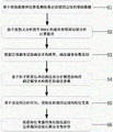
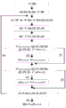
fig. 1 is a flowchart of an anchoring slope safety evaluation method based on a particle swarm algorithm and discrete element analysis in the embodiment of the present invention.
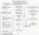
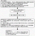
Fig. 2 is a flow chart of an implementation of the method for evaluating the long-term safety of the anchored slope based on a particle swarm algorithm and a discrete element analysis method in the embodiment of the invention.
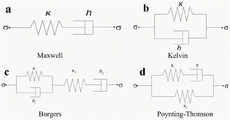
Fig. 3 is a schematic diagram of a component model commonly used in the embodiment of the present invention.
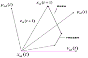
FIG. 4 is a diagram illustrating a particle location update method according to an embodiment of the present invention.
FIG. 5 is a flow chart of an implementation of a particle swarm algorithm in an embodiment of the present invention.
FIG. 6 is a flow chart of the calculation and analysis of 3DEC software in the embodiment of the present invention.
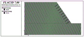
FIG. 7 is a 3DEC rock-anchored slope analysis and calculation model in the embodiment of the invention.
Figure 8 is a strain-time curve of a rock mass at a confining pressure of 200kpa in an embodiment of the invention.
FIG. 9 is a typical strain-time curve of the Burgers model in an embodiment of the present invention.
FIG. 10 is a Burgers-mohr model in an embodiment of the invention.
Fig. 11 is a graph showing the variation of the objective function value of the particle swarm algorithm with the number of iterations in the embodiment of the present invention.
Fig. 12 is a diagram of a slope surface monitoring position and an anchor cable position in an embodiment of the invention.
FIG. 13 is a graph showing the time-dependent displacement of the slope table feature point in the X direction in the embodiment of the present invention.
FIG. 14 is a graph of cable bolt axial force versus time for an embodiment of the present invention.
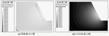
FIG. 15 is a diagram illustrating a displacement field of a rock anchored slope and a stress distribution of anchor lines in an embodiment of the present invention.
Detailed Description
For a more clear understanding of the technical features, objects and effects of the present invention, embodiments of the present invention will now be described in detail with reference to the accompanying drawings.
The embodiment of the invention provides an anchoring slope safety evaluation method based on a particle swarm algorithm and discrete element analysis. At present, the design of the rock anchoring side slope is commonly carried out by methods such as the technical specification GB50330-2013 of the building side slope engineering and the technical specification GB50086-2015 of the rock-soil anchor rod and shotcrete support engineering, and the side slope anchoring design is carried out based on a limit balance analysis method only by considering the action of an anchor rope as a uniformly distributed force. The conventional slope evaluation methods such as the simple segmentation method, the Bischopper method, the Swedish segmentation method and the like are all based on that the static analysis just equates the action of the anchor cable into a uniformly distributed force and the static stability condition of the whole slope is calculated. And the creep effect of the rock mass is not considered. The method has two innovations: firstly, the interaction of the anchor cable and the rock body and the action of the rock slope structural surface (discontinuous surface) can be considered by fully utilizing the discrete element analysis method. Second, the impact of rock creep on the long-term safety of the lithologic anchored slope may be considered. And the safety and time hook is dynamically analyzed, and the change of the slope safety along with the rock creep is fully considered. Thirdly, the experimental data and the field dynamic monitoring data are fully utilized, the particle swarm algorithm and the discrete element analysis software are combined, and the automatic and accurate determination of the rock anchoring slope analysis calculation model parameters is realized. The calculation response of the whole rock anchoring slope analysis and calculation model is more in line with the actual engineering situation, and the evaluation result is more accurate. The implementation of the method is not that the results are combined and optimized after simple respective calculation, but the optimization calculation of the particle swarm algorithm is carried out by dynamically combining the discrete element analysis method based on the combination of the python language programming and the calculation of each generation of the particle swarm algorithm with the discrete element analysis calculation process, and the combination method is put forward for the first time.
Referring to fig. 1-2, fig. 1 is a flowchart of an anchor slope safety evaluation method based on a particle swarm algorithm and a discrete element analysis in an embodiment of the present invention, and fig. 2 is a flowchart of an implementation of an anchor slope long-term safety evaluation method based on a particle swarm algorithm and a discrete element analysis in an embodiment of the present invention, which specifically includes the following steps:
s1: and collecting basic data of the rock anchoring side slope based on field investigation and instrument monitoring.
And (3) surveying and collecting landslide form data according to the site of the anchored rock slope, for example: the elevation of the anchoring side slope, the landslide boundary, the form and distribution characteristics of the structural surface, the deformation characteristics of the side slope and the like. And collecting deformation data of the anchoring side slope, stress data of the anchoring structure and the like according to a field monitoring instrument. For example: and collecting slope surface displacement data based on the GPS monitoring pier and collecting the change condition of the anchor cable anchoring force based on the anchor cable dynamometer. And confirming the installation angle, the length, the strength of the grouting body and the like of the anchor cable according to the design and construction data. And confirming the mechanical parameters, creep test data and the like of the rock anchoring side slope according to the test data.
S2: and constructing a rock anchoring slope analysis calculation model based on discrete element analysis software 3 DEC.
And (3) constructing a rock anchoring slope analysis calculation model in 3DEC discrete element analysis software based on the data collected in the step (1). And secondary influence factors are ignored, and primary influence factors are considered, so that the computing efficiency of the software is improved.
S3: determining a creep constitutive model and a creep parameter range according to a rock creep test, wherein the concrete implementation steps of the step S3 are as follows:
s3-1: a creep constitutive model is determined. At present, creep constitutive models most commonly used for creep analysis of rock and soil are divided into two types, namely empirical models formed based on tests and data fitting and element models obtained through theoretical analysis. However, empirical models lack theoretical basis and are only fit to experimental data. The element model can reflect the mechanical property of the rock-soil body more truly, and is simple and easy to use, so that the element model is more widely used in actual engineering. The most commonly used original models are Kelvin model, Maxwell model, poling-Thomson model, Burgers model, etc. as shown in fig. 3, a is Maxwell element model, b is Kelvin element model, c is Burgers element model, and d is poling-Thomson element model.
The method adopts a method of triaxial creep test and element model curve analogy to determine the basic type of a creep constitutive model. The specific process is that firstly, the triaxial creep test data of the rock mass is collated to obtain the axial strain-time relation curve under different confining pressures. Then, determining the type of elements, such as elastic elements, viscous elements and the like, which the model should contain according to the curve characteristics; finally, a model containing the elements is selected from the models, and a typical strain-time curve is compared with the test result to determine the basic type of the creep structure.
S3-2: and estimating the parameter range of the creep constitutive model based on the triaxial creep test data. The conventional creep constitutive model is expressed as follows:
the Maxwell constitutive model is shown as a in FIG. 3, and the stress-strain relationship is as follows:

where k is the elastic modulus, η is the viscosity coefficient, σ is the stress, and ε is the strain.
A Kelvin constitutive model is shown as b in fig. 3, and the stress-strain relation is as follows:

where k is the elastic modulus, η is the viscosity coefficient, σ is the stress, and ε is the strain.
③ Burgers constitutive model is shown as c in FIG. 3, and the stress-strain relation is:

wherein k is the modulus of elasticity, wherein k1Is the elastic modulus, k, of the Kelvin body in the model of the element2Is the elastic modulus of Maxwell body in the element model, and eta is the viscosity coefficient, wherein eta is1Is the viscosity coefficient, η, of the Kelvin body in the model of the component2The viscous coefficient of Maxwell body in the element model is shown, sigma is stress, and epsilon is strain.
The Poynting-Thomson constitutive model is shown as d in FIG. 3, and the stress-strain relation is as follows:

in the formula k1Is the elastic modulus, k, of the Maxwell body in the element model2The elastic modulus of the spring in the element model, eta is the viscosity coefficient, sigma is the stress, and epsilon is the strain.
S4: assigning the creep constitutive model determined in the step S3 to the rock anchoring slope analysis and calculation model constructed in the step S2 in 3DEC software, taking the creep parameter range determined in the step S2 as an input parameter of a particle swarm algorithm, combining the responses of the particle swarm algorithm and the rock anchoring slope analysis and calculation model, and performing combined iterative calculation to determine the optimal parameter of the creep constitutive model in the rock anchoring slope analysis and calculation model; the method comprises the following concrete steps:
s4-1: and writing a particle swarm algorithm through python, and combining the response of a rock anchoring slope analysis calculation model in 3DEC software with the target function of the particle swarm algorithm. And simultaneously determining the optimal parameters of the creep constitutive model by means of the field monitoring data of the anchored slope.
The particle swarm algorithm searches all particles in a D-dimensional space, the advantages and disadvantages of the current particle position are judged through a fitness function, and the fitness value of the particle swarm is determined by an objective function. The particles can remember the optimal solution of the particles in the iterative updating process and the group optimal solution of all the particles according to the adaptive value and the memory function, the particles can be influenced by the current position and speed when the positions of the particles are updated, and the update positions and speeds of the group particles can be adjusted according to the individual optimal and global optimal conditions, so that the overall optimal state of the group is ensured, and the global optimal solution is found.
As shown in fig. 4, the principle of the particle swarm optimization algorithm to solve the optimal solution is as follows:
in the D-dimensional space, there are N particles, and the position vector of particle i is as follows:
xi=(xi1,xi2,...,xiD),i=1,2,...n
the velocity of particle i is expressed as follows:
vi=(vi1,vi2,...,viD)
the best positions that the individual particles i have experienced, i.e. the individual optima pbest, are expressed as follows:
pi=(pi1,pi2,...,piD)
the global optimum is gbest, i.e. the best position of the population history, as follows:
pg=(pg1,pg2,...,pgD)
the change in position of the particles being limited to [ X ]min,d,Xmax,d]。
The d-dimension velocity update formula of the particle i is as follows:
vid(t+1)=vid(t)+c1r1(t)(pid(t)-xid(t))+c2r2(t)(pgi(t)-xid(t))
the d-dimension position update formula of the particle i is as follows:
xid(t+1)=xid(t)+vid(t+1)
in the formula: d-particle dimension
i-ith particle
c1-an acceleration constant for adjusting the flight of the particles to an individual optimum value
c2-an acceleration constant for adjusting the particle towards a global optimum
r1-adjusting a random function of the relationship between the particles and the individual optimum, taking r1∈[0,1]
r2-adjusting a random function of the relation between the particles and the global optimum, taking r2∈[0,1]
The particle position updating method is shown in fig. 4, and the particle swarm algorithm is implemented as follows:
(1) initializing the population of particles includes random position and velocity. The method selects parameters of a rock mass creep constitutive model as target parameters;
(2) determining a fitness function and calculating a fitness function value;
(3) determining the optimal position of individual history, after calculating the fitness function value of the particles, comparing and updating to determine the latest optimal value of the individual;
(4) determining a global optimal position, and after obtaining a fitness function value of the particle, comparing the current function value with the global optimal position so as to update the optimal value of the population;
(5) updating the speed and the position of the particles in the population according to a formula;
(6) and (5) performing loop iteration, returning to the second step to perform calculation again if the optimal result is not achieved, and continuously cycling the process for a plurality of times until the end condition is met.
The implementation process of the particle swarm algorithm is shown in fig. 5, and in order to facilitate calculation, the particle swarm algorithm calculation program is written by using python language according to the principle of the particle swarm algorithm.
Python writes a particle swarm algorithm parameter description:
the objective function func: objective function
Target dimension ndim: the dimension of the objective function, typically the number of parameters
Population size _ pop: the particle size represents the number of particles required to perform the calculation. The larger the population size is, the more information is exchanged among the particles, so the optimization performance is better, but when the population of the particles reaches a certain number, the improvement of the algorithm in increasing the number of the particles is small, and the efficiency of the particle swarm algorithm is also influenced.
Maximum number of iterations max _ lite: maximum number of iterations in solving the optimum process
Parameter ranges lb and ub: the method refers to the upper and lower limits of a parameter, generally sets the parameter range of an optimization problem as the value range of particles, generally, the change of the particles in each dimension cannot exceed a set boundary value, and the ranges of the particles with different dimensions can be set differently, and the particle ranges are set to different values according to specific problems.
Inertial weight: the search range of the particles can be limited through adjustment, so that the particles have inertia and space search capability of keeping motion. Promote the balance of the global and the local, search in the new area. Setting a large value facilitates the search field, and a small value facilitates the local search. The appropriate inertial weight ω will affect the search speed and accuracy of the particle swarm algorithm.
Individual and group memory c1, c 2: two aspects of learning are reflected: the first is self historical experience, and the second is the optimal particle in the population. The parameter reflects the information exchange of the particle swarm, in the aspect of adjusting the parameter, the larger or smaller parameter cannot be set, the larger c1 diverges, the larger c2 converges early, generally, c1 and c2 are fixed constants, and c1 and c2 are equal; in many documents c1 and c2 have values in the range of [0,4 ].
S4-2: and importing the engineering example monitoring data collected in the step S1 into python, and summing the differences between the displacement of the plurality of slope table monitoring points of the 3DEC model in the X direction and the corresponding actual monitoring data to obtain an objective function.
S4-3: and importing a particle swarm algorithm by means of an ipython writing environment built in 3DEC software, and setting corresponding parameters. And performing combined iterative computation of the particle swarm algorithm and the analytical computation of the rock anchoring slope analytical computation model, continuously obtaining a fitness value, and finally obtaining the optimal constitutive model parameters which best meet the actual monitoring data. As shown in fig. 2.
S5: and extracting characteristic variables of the rock anchoring side slope based on the set rock anchoring side slope analysis time.
Step S5-1: and assigning the creep constitutive model determined in the steps S3 and S4 and the optimal parameters to the rock anchoring slope analysis and calculation model constructed in the step S2.
3DEC software computational analysis rationale:
the discrete unit method only needs to satisfy the equilibrium equation, and the deformation body still needs to conform to the constitutive equation.
(1) Physical equation
Two blocks that interact in discrete element analysis need to satisfy the following physical constitutive equations:
ΔFn=KnΔUn
ΔFs=KsΔUs
Fn=Fn1+KnΔUn
Fs=Fs1+KsΔUs
in the formula Kn、KsFor normal and tangential contact stiffness of the joint surfaces,ΔFn、ΔFsIncrement of normal and tangential forces between blocks, Δ Un、ΔUsIn increments of normal and tangential displacement between blocks, Fn、FsNormal and tangential forces between blocks, Fn1、Fs1The initial values of the normal force and the tangential force between the blocks or the final value of the last iteration.
(2) Equation of motion
The fundamental newton's second law of the discrete element method, the force acting on a discrete mass causes the mass to move, and the centroid of the mass should satisfy the following equation:


a=Fcombination of Chinese herbs/m

In the formula, Fxi、FyiSubjecting the block to the action of another block, Fx、FyThe resultant horizontal and vertical forces to which the block is subjected. M is the resultant moment, x, to which the block is subjectedi、yiIs the coordinate of the action point, x and y are the coordinates of the centroid of the block body, a is the acceleration, m is the mass of the rock mass, angular acceleration, I moment of inertia.
(3) And (4) carrying out numerical integration by adopting a forward difference format to obtain the speed and displacement of the block along the resultant force direction and the rotation quantity of the block.
V(t1)=V(t0)+aΔt
U(t1)=U(t0)+V(t1)Δt

In the formula, t0For the initial time, Δ t is the calculation time step, U (t)1)、V(t1) Respectively is a block body at t1Displacement and velocity in time, θ (t)1) Is t1Displacement and velocity in time, θ (t)1) Is t1Moment of inertia of time.
The 3DEC software computational analysis process is shown in fig. 6.
Step S5-2: and according to the data collected in the step S1, setting the characteristic position of the rock anchoring slope analysis and calculation model for deformation monitoring based on the arrangement condition of the on-site monitoring instrument, and monitoring the axial force change condition of the anchor cable.
Step S5-3: and inputting the set rock mass anchoring side slope analysis time, and extracting the monitoring variable of the characteristic position and the axial force value of the anchor cable as characteristic variables.
S6: and (4) according to the change condition of the characteristic variable, performing long-term safety evaluation on the rock mass anchoring side slope.
Step S6-1: and (5) constructing a change curve of the displacement along with the time and a change curve of the axial force of the anchor cable along with the time on the basis of the characteristic variables extracted in the step (5).
Step S6-2: and observing whether the displacement change curve shows a convergence trend or not and whether the axial force change curve of the anchor cable converges or not. And calculating the maximum variation amplitude of the axial force of the anchor cable. And (5) evaluating the long-term safety of the rock anchoring side slope.
The method is based on a particle swarm algorithm and a discrete element analysis method, a rock anchoring side slope creep deformation analysis model is constructed in 3DEC software, the particle swarm algorithm is combined with field monitoring data to determine the optimal parameters of the creep constitutive model, the two analysis methods are combined through a python writing program, the evaluation accuracy and efficiency are improved, meanwhile, the long-term deformation characteristics and the evolution mechanism of the rock anchoring side slope under the creep condition are disclosed, the dynamic evaluation on the long-term safety of the rock anchoring side slope is realized, and a foundation is provided for prediction, early warning and prevention of the same type of side slope.
The selected example of the method is a rock anchoring side slope of a certain hydropower project in the southwest region. The side slope is positioned on the right bank of a river with the upstream of a hydropower station dam site being about 11.5km, the length of the landslide is about 700m, the width of the landslide is about 320-400 m, and the area of the landslide is about 0.25km2The total amount of the formula is about 1300 km3。
In this embodiment, the basic data of the rock anchoring side slope collected based on site survey, construction data, design data, test data and instrument monitoring in step 1 are shown in table 1 below:
TABLE 1 landslide rock mass related parameter values

Wherein rho is the density of the rock mass, G is the shear modulus of the rock mass, K is the bulk modulus of the rock mass, C is the cohesion of the rock mass, dip is the inclination angle of the rock stratum, dip-direction is the inclination of the rock stratum, spacing is the rock stratum gap, num is the number of the rock stratum, stiffness-normal is the normal stiffness of the rock stratum, and stiffness-shear is the tangential stiffness of the rock stratum.
The relevant parameters of the cable bolt are shown in table 2 below:
TABLE 2 Anchorage Cable related parameter values

The area is the cross-sectional area of the anchor cable, e is the elastic modulus of the anchor cable, grout _ stiff _ is the rigidity of the grouting body, cable _ yield is the axial yield strength of the anchor cable, cable _ strain _ limit is the axial strain limit of the anchor cable, dowel _ stiff _ is the shear deformation rigidity of the anchor cable, dowel _ yield _ is the shear yield strength of the anchor cable, and dowel _ strain _ limit is the shear strain limit of the anchor cable.
In this embodiment, the specific implementation steps of the step 2 of constructing the rock anchoring slope analysis calculation model based on the discrete element analysis software 3DEC are as follows:
and constructing a rock anchoring slope analysis calculation model based on the data collected in the step S1, wherein the length of the model is 700m, the height of the model is 400m, and the inclination angle is about 55 degrees. Because two-dimensional computational analysis of the profile of the anchored rock slope needs to be carried out, the width, i.e. the Y direction, is only 5 m. The joint model is inclined to the inclination angle of 70 degrees and inclined to the inclination angle of 270 degrees, the length of anchor cables is 50m and the interval is 20m, and the installation angle is about 35 degrees. The remaining calculation parameters required for the calculation in 3DEC were assigned to the analytical model according to the values shown in table 2 and table 3.
The established rock anchoring slope analysis and calculation model is shown in fig. 7, in the embodiment, the concrete implementation steps of determining a creep constitutive model and determining a creep parameter range according to a rock creep test in the step 3 are as follows:
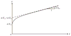
step S2-1: according to the creep test of the rock sample, the test data is obtained, and figure 8 is a test curve obtained when the confining pressure is 200 kPa. The curve exhibits 2 more obvious characteristics: 1. the specimen undergoes significant instantaneous elastic deformation in a short time after the application of the load, so the model should contain elastic elements; 2. as the test progresses, the specimen exhibits a pronounced creep-slowing phenomenon, which over time remains unchanged in creep rate, exhibiting viscoelastic characteristics, so that the model should comprise viscous elements. Through comparative analysis with a common creep constitutive model, a typical strain-time curve (fig. 9) of the Burgers model is found to be most similar to the curve. Therefore, the constitutive model of the rock mass is preliminarily determined to be a Burgers model. As the damage condition of the rock slope needs to be considered in the long-term safety evaluation, an M-C element is connected in series, so that the combined molar coulomb damage rule is combined. And the model becomes a Burgers-mohr model (fig. 10).
Step S2-2: the Burgers-mohr model comprises 6 parameters in total, c, EM、ηM、EK、ηKRespectively is cohesion and internal frictionWipe angle, modulus of elasticity, maxwell coefficient of viscosity, viscoelastic modulus, and kelvin coefficient of viscosity. C and
 the parameters have been determined experimentally for routine strength. Four parameters are therefore also determined. The stress-time relationship of the Burgers-mohr model can be simplified as:

wherein σ is stress; ε is the strain.
From the test curve (FIG. 8), the initial strain ε of the model can be found0And a slope m at steady creep. When t is 0, epsilon can be obtained based on the formula (5)0=σ/EM(ii) a When t takes a large value, the value of, so that m is 1/ηM(ii) a The parameter E can be determined based on the least square methodM、ηM. The fitting parameters of the final constitutive model of rock are shown in table 3.
TABLE 3 rock creep parameters

The value ranges determined according to table 3 are shown in table 4 below:
TABLE 4 range of constitutive model parameters of rock mass

In this embodiment, the step S4 is implemented specifically by determining the optimal parameters of the rock anchoring slope based on the responses of the particle swarm algorithm and the rock anchoring slope analysis and calculation model and the actual monitoring data of the site as follows:
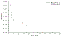
from table 4, the value range of the rock mass creep parameters can be obtained, and the values are brought into a particle swarm algorithm written by python by means of an ipyhon programming tool carried by 3DEC software, and the calculation parameters are used when an initial particle swarm is generated. And summing the displacement of a plurality of slope table monitoring points X of the 3DEC model and the difference of corresponding actual monitoring data as an objective function. Therefore, the parameter conditions of the particle swarm algorithm are shown in the following table 5, and the combined calculation of the particle swarm algorithm and the 3DEC discrete element algorithm is performed by combining the 3DEC analysis model constructed in step 2 after the parameters are introduced. The variation of the objective function value with the number of iterations is shown in fig. 11 below.
TABLE 5 engineering example particle swarm algorithm parameter Table


As can be seen from fig. 11, as the iterative objective function value of the particle swarm algorithm is smaller, it is shown that the response of the 3DEC rock mass anchoring slope analysis calculation model is closer to the real monitoring data as the particle swarm algorithm is iterated, that is, the creep parameter approaches the optimal value gradually. And the target function value tends to be stable around 40 generations, the convergence is fast, and the optimal value is reached around 40 generations.
The calculation result shows thatM=19988.6661MPa、ηM=1.33E+07MPa·h、EK=41211.29717MPa、ηKAnd when the pressure is 254009.3004 MPa.h, the response of the characteristic position characteristic variable of the rock anchoring slope analysis calculation model is closest to the monitoring value. And selecting the group of parameters as the optimal parameters of the constitutive model of the rock anchoring slope.
In this example, if the step S5 is based on the set rock-anchored slope analysis time, the specific implementation of extracting the characteristic variables of the rock-anchored slope is as follows:
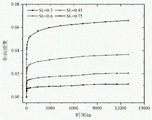
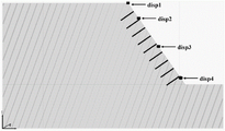
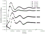
and substituting the creep constitutive model determined in the step S3 and the optimal parameters determined in the step S4 into the rock mass anchoring slope analysis and calculation model constructed in the step S2. Inputting the predicted set rock anchoring slope analysis time, extracting 120 days of predicted creep analysis time in the embodiment, and extracting the horizontal displacement of 4 characteristic positions of the slope table and the change data of anchor cable load along with time. The characteristic positions of the slope surface and the positions of the anchor lines are shown in fig. 12, and the extracted characteristic variables and the axial force data of the anchor lines are shown in fig. 13 and 14.
In this embodiment, the step S6 of evaluating the long-term safety of the rock mass anchored slope according to the variation of the characteristic variable specifically includes:
as can be seen from fig. 13, the characteristic variable increases sharply from the beginning as time increases. The anchor cable finally tends to be stable after undergoing a plurality of fluctuations, and the change rule of the axial load of the anchor cable is that the anchor cable finally tends to be stable after undergoing fluctuations from the beginning to the end when the anchor cable is just installed and the anchoring effect is initially exerted and rapidly increased to the end when the anchor cable is slowly increased. After stabilization, the load of the anchor cable does not generate mutation, and the fluctuation range is less than 10%. Based on a judgment threshold value provided by 'long-term performance and safety evaluation of geotechnical anchoring engineering', the anchor cable can be judged to be safe when the load fluctuation range is less than 10%, and the long-term safety of the anchoring slope is judged by combining the change trend analysis of characteristic variables: and (4) safety.
As can be seen from Table 5, the accuracy of the response of the rock mass anchoring slope analysis and calculation model tends to be stable finally as the iteration of the particle swarm algorithm is continuously increased, which shows that the particle swarm algorithm can rapidly and accurately determine the parameters of the rock mass creep constitutive structure according to the actual monitoring condition. The change of the characteristic variable along with time is shown in figure 13, and the combination of the field monitoring condition is shown in figure 14, which shows that the long-term safety of the rock anchoring side slope is a dynamic change process, but the conventional evaluation methods are static and inaccurate at present. The method provided by the method not only considers the interaction between the anchoring structure and the rock mass, but also considers the influence of the characteristics (creep, structural plane and the like) of the rock slope rock-soil mass, hooks the safety of the rock slope with the time, and realizes the dynamic evaluation of the safety of the rock slope. Meanwhile, the method can also predict data such as a displacement field of the anchored slope after the preset analysis time, a stress field of the anchor cable and the like, as shown in fig. 15.
At present, the parameter confirmation mode of the constitutive model in the discrete element analysis is mainly to endow a determined value through indoor tests. The inversion analysis is carried out by combining with on-site monitoring data, whether the response of the rock anchoring slope analysis and calculation model meets on-site monitoring, deformation signs and the like is mainly checked through manual trial, and the efficiency and the accuracy are low. The method combines the particle swarm algorithm and the discrete element analysis method, realizes automatic optimization of constitutive parameters of the rock anchoring slope analysis and calculation model, improves the working efficiency and increases the accuracy. The following advantages of the particle swarm algorithm are fully utilized:
(1) the particle swarm algorithm completes searching according to the speed of the particles, has memory capacity, and has high convergence speed and less parameter setting.
(2) The particle swarm algorithm is simple in principle and structure, does not need to be crossed or varied, has memorability and is easy to operate and implement.
(3) The particle swarm algorithm has good characteristics, the particles are self-updated according to the historically optimal particles and the globally optimal positions and speeds of the particles, the searching efficiency is high, and the good effect is shown.
The method combines genetic algorithm and discrete element analysis method through an IPython platform carried by 3DEC software by using python language programming. The evaluation method proposed by the method is not simple to combine results after independently calculating the two evaluation methods. Instead, the objective function calculated in each generation dynamically extracts the analysis result from the discrete element analysis, and the generation of new particle positions in each generation dynamically assigns new parameter values to the discrete elements for dynamic calculation as shown in fig. 2. And finally determining creep constitutive model parameters which best meet the field monitoring data after iterative computation of a particle swarm algorithm and a discrete element analysis method. The method is currently applied for the first time.
The invention has the beneficial effects that: the method effectively improves the accuracy and the efficiency of evaluating the safety of the rock anchored slope and provides favorable conditions for researching the evolution mechanism of the rock anchored slope landslide and evaluating the dynamic safety.
The above description is only for the purpose of illustrating the preferred embodiments of the present invention and is not to be construed as limiting the invention, and any modifications, equivalents, improvements and the like that fall within the spirit and principle of the present invention are intended to be included therein.
Claims (4)
1. An anchoring slope safety evaluation method based on particle swarm optimization and discrete element analysis is realized by means of 3DEC software, and is characterized in that: the method comprises the following steps:
s1: collecting basic data of the rock anchoring side slope based on-site investigation and instrument monitoring;
s2: according to the basic data, utilizing discrete element analysis software 3DEC to construct a rock anchoring slope analysis calculation model;
s3: determining a creep constitutive model and a creep parameter range according to a rock creep test;
s4: assigning the creep constitutive model determined in the step S3 to the rock anchoring slope analysis and calculation model constructed in the step S2 in 3DEC software, taking the creep parameter range determined in the step S3 as an input parameter of a particle swarm algorithm, combining the responses of the particle swarm algorithm and the rock anchoring slope analysis and calculation model, and performing combined iterative calculation to determine the optimal parameter of the creep constitutive model in the rock anchoring slope analysis and calculation model;
s5: substituting the optimal parameters of the creep constitutive model obtained in the step S3 and the optimal parameters of the creep constitutive model in the rock anchoring slope analysis and calculation model obtained in the step S4 into the rock anchoring slope analysis and calculation model constructed in the step S2, and extracting characteristic variables of the rock anchoring slope based on the set rock anchoring slope analysis time;
the process of extracting the characteristic variables of the rock anchoring side slope is as follows:
s5-1: assigning the creep constitutive model determined in the step S3 and the step S4 and the optimal parameters to the rock mass anchoring slope analysis and calculation model constructed in the step S2;
s5-2: according to the data collected in the step S1, based on the arrangement condition of the on-site monitoring instrument, setting the characteristic position of the rock anchoring slope analysis and calculation model for deformation monitoring, and monitoring the axial force change condition of the anchor cable;
s5-3: inputting set rock mass anchoring side slope analysis time into 3DEC software, and extracting by taking a monitoring variable of a characteristic position and an axial force value of an anchor cable as characteristic variables;
s6: according to the change condition of the characteristic variable, performing long-term safety evaluation on the rock anchoring side slope;
the process of evaluating the long-term safety of the rock anchored slope is as follows:
s6-1: constructing a displacement change curve of the change of the displacement along with the time and an axial force change curve of the change of the axial force of the anchor cable along with the time based on the characteristic variables extracted in the step S5;
s6-2: and evaluating the long-term safety of the rock-anchored slope based on the displacement change curve, the axial force change curve of the anchor cable and the maximum change amplitude of the axial force of the anchor cable, wherein when the displacement change curve and the axial force change curve of the anchor cable both show convergence and the maximum change amplitude of the axial force of the anchor cable is less than or equal to 10%, the slope is evaluated as safe, otherwise, the slope is unsafe.
2. The method for evaluating the safety of the anchored slope based on the particle swarm optimization and the discrete element analysis according to claim 1, wherein: in step S1, the basic data includes shape data obtained from field survey, deformation data of the anchoring side slope and stress data of the anchoring structure obtained from monitoring by an instrument, and the shape data includes elevation of the anchoring side slope, landslide boundary, shape and distribution characteristics of the structural plane, and deformation characteristics of the side slope.
3. The method for evaluating the safety of the anchored slope based on the particle swarm optimization and the discrete element analysis according to claim 1, wherein: in step S3, the process of determining the creep constitutive model and the creep parameter range according to the rock creep test is as follows:
firstly, arranging triaxial creep test data of a rock mass to obtain axial strain-time relation curves under different confining pressures, then determining element types contained in an element model according to the characteristics of the axial strain-time relation curves, finally selecting the element model containing the element types, comparing a typical strain-time curve of the element model with a test result of a triaxial creep test, and determining a creep constitutive model;
and estimating the parameter range of the creep constitutive model based on the triaxial creep test data.
4. The method for evaluating the safety of the anchored slope based on the particle swarm optimization and the discrete element analysis according to claim 1, wherein: in step S4, the process of determining the optimal parameters of the creep constitutive model in the rock anchored slope analysis calculation model is as follows:
s4-1: combining lithology anchoring slope analysis calculation model response in 3DEC software with a target function of a particle swarm algorithm by compiling the particle swarm algorithm through python;
s4-2: importing the instrument monitoring data collected in the step S1 into python in the step S4-1, and summing the displacement of a plurality of slope table monitoring points in the 3DEC software in the X direction and the difference value of corresponding actual monitoring data to obtain a target function;
s4-3: importing a particle swarm algorithm by means of an IPython compiling environment built in 3DEC software, and setting corresponding parameters, wherein the corresponding parameters comprise: the method comprises the steps of performing a target function func, a target dimension ndim, a population scale size _ pop, a maximum iteration number max _ lite, a parameter lower limit lb, a parameter upper limit ub, an inertia weight, an individual memory and a population memory c1 and c2, performing combined iterative computation of analysis and computation of a particle swarm algorithm and a rock anchoring slope analysis and computation model, combining field monitoring data, continuously obtaining a fitness value, and finally obtaining the optimal parameters of a creep constitutive model which best accord with actual monitoring data.
Priority Applications (1)
| Application Number | Priority Date | Filing Date | Title |
|---|---|---|---|
| CN202110430588.4A CN113431056B (en) | 2021-04-21 | 2021-04-21 | Anchoring slope safety evaluation method based on particle swarm algorithm and discrete element analysis |
Applications Claiming Priority (1)
| Application Number | Priority Date | Filing Date | Title |
|---|---|---|---|
| CN202110430588.4A CN113431056B (en) | 2021-04-21 | 2021-04-21 | Anchoring slope safety evaluation method based on particle swarm algorithm and discrete element analysis |
Publications (2)
| Publication Number | Publication Date |
|---|---|
| CN113431056A CN113431056A (en) | 2021-09-24 |
| CN113431056B true CN113431056B (en) | 2022-01-28 |
Family
ID=77753328
Family Applications (1)
| Application Number | Title | Priority Date | Filing Date |
|---|---|---|---|
| CN202110430588.4A Active CN113431056B (en) | 2021-04-21 | 2021-04-21 | Anchoring slope safety evaluation method based on particle swarm algorithm and discrete element analysis |
Country Status (1)
| Country | Link |
|---|---|
| CN (1) | CN113431056B (en) |
Families Citing this family (3)
| Publication number | Priority date | Publication date | Assignee | Title |
|---|---|---|---|---|
| CN114722478B (en) * | 2022-04-29 | 2024-01-05 | 山西省交通规划勘察设计院有限公司 | Clastic rock contact model parameter acquisition method and slope stability analysis method |
| CN115422818B (en) * | 2022-11-03 | 2023-02-10 | 北京云庐科技有限公司 | Discrete element parallel real-time simulation slope early warning system and method based on cloud service |
| CN116629081B (en) * | 2023-07-25 | 2023-09-26 | 贵州正业工程技术投资有限公司 | Method and device for calculating finite element instantaneous deformation of stone filler foundation |
Citations (6)
| Publication number | Priority date | Publication date | Assignee | Title |
|---|---|---|---|---|
| RU2034957C1 (en) * | 1991-01-08 | 1995-05-10 | Юрий Петрович Кожин | Creep resistant construction |
| CN104179176A (en) * | 2014-08-08 | 2014-12-03 | 山东科技大学 | Anchor wire prestress loss and rock-soil body creep coupling based computing method for side slope creep values |
| CN110750871A (en) * | 2019-09-23 | 2020-02-04 | 湘潭大学 | Friction type granular material creep test simulation method based on discrete elements |
| CN111090921A (en) * | 2019-07-23 | 2020-05-01 | 中国地质大学(武汉) | Safety evaluation method for slope anchoring structure system |
| CN111104762A (en) * | 2019-12-26 | 2020-05-05 | 湘潭大学 | Three-axis creep test simulation method for cementing material based on discrete elements |
| CN111666671A (en) * | 2020-05-29 | 2020-09-15 | 中南大学 | Real-time inversion method for creep parameters of surrounding rock mass |
-
2021
- 2021-04-21 CN CN202110430588.4A patent/CN113431056B/en active Active
Patent Citations (6)
| Publication number | Priority date | Publication date | Assignee | Title |
|---|---|---|---|---|
| RU2034957C1 (en) * | 1991-01-08 | 1995-05-10 | Юрий Петрович Кожин | Creep resistant construction |
| CN104179176A (en) * | 2014-08-08 | 2014-12-03 | 山东科技大学 | Anchor wire prestress loss and rock-soil body creep coupling based computing method for side slope creep values |
| CN111090921A (en) * | 2019-07-23 | 2020-05-01 | 中国地质大学(武汉) | Safety evaluation method for slope anchoring structure system |
| CN110750871A (en) * | 2019-09-23 | 2020-02-04 | 湘潭大学 | Friction type granular material creep test simulation method based on discrete elements |
| CN111104762A (en) * | 2019-12-26 | 2020-05-05 | 湘潭大学 | Three-axis creep test simulation method for cementing material based on discrete elements |
| CN111666671A (en) * | 2020-05-29 | 2020-09-15 | 中南大学 | Real-time inversion method for creep parameters of surrounding rock mass |
Non-Patent Citations (1)
| Title |
|---|
| 呷爬滑坡滑带土蠕变特性及其稳定性;张晓奇等;《地质科技通报》;20201130;第39卷(第6期);第145-153页 * |
Also Published As
| Publication number | Publication date |
|---|---|
| CN113431056A (en) | 2021-09-24 |
Similar Documents
| Publication | Publication Date | Title |
|---|---|---|
| CN113431056B (en) | Anchoring slope safety evaluation method based on particle swarm algorithm and discrete element analysis | |
| CN113408184B (en) | Anchoring slope safety evaluation method based on genetic algorithm and discrete element analysis method | |
| Shahin et al. | Behavior of ground and response of existing foundation due to tunneling | |
| JP3692507B2 (en) | Liquefaction prediction system | |
| Wang et al. | Construction of 3D creep model of landslide slip-surface soil and secondary development based on FLAC3D | |
| Zhao et al. | Progressive failure processes of reinforced slopes based on general particle dynamic method | |
| Chang et al. | Sensitivity analysis of factors affecting time-dependent slope stability under freeze-thaw cycles | |
| CN104182646A (en) | Three dimensional earthquake side slope landslide occurring time forecasting method based on slide displacement analysis | |
| Gao et al. | MPM modeling of pile installation in sand: Contact improvement and quantitative analysis | |
| Zhu et al. | The application of MsPSO in the rockfill parameter inversion of CFRD | |
| Al-Jeznawi et al. | A soil-pile response under coupled static-dynamic loadings in terms of kinematic interaction | |
| Sabzi et al. | The performance of buildings adjacent to excavation supported by inclined struts | |
| Wang et al. | Inverse parametric analysis of seismic permanent deformation for earth-rockfill dams using artificial neural networks | |
| Lu et al. | Numerical and experimental analyses for bearing capacity of rigid strip footing subjected to eccentric load | |
| Soleimanian et al. | Effects of constitutive soil models on the seismic response of an offshore jacket platform in clay by considering pile-soil-structure interaction | |
| Jacazz et al. | Evaluation of Analytical and Numerical Techniques to Simulate Curtain Pile Walls in a Tropical Soil of the Federal District of Brazil. | |
| Maarouf et al. | Prediction of surrounding effects in soft soil deposits due to piling-A study of comparing different prediction methods | |
| Oberender et al. | Mechanical Models for Hazard and Risk Analysis of Structures in Creeping Landslides. | |
| Raharja et al. | Parametric study of tunnel analysis in clay shale on short term and long-term conditions using finite element method | |
| Iftekharuzzaman et al. | Numerical modeling of lateral response of long flexible piles in sand | |
| Jamiolkowski et al. | RESEARCH APPLIED TO GEOTECHNICAL ENGINEERING. JAMES FORREST LECTURE. | |
| Wang et al. | Dynamic Parameters Updating of Earth-rock Dams Based on Modal Parameter Identification | |
| Liu et al. | Soil parameters inversion and influence based on MIDAS GTS | |
| Tao et al. | Disturbance mechanism analysis of pipe jacking crossing existing subway tunnel based on BPNN parameter inversion | |
| Awad | ANALYSIS AND ASSESSMENT OF LARGE DIAMETER PILE |
Legal Events
| Date | Code | Title | Description |
|---|---|---|---|
| PB01 | Publication | ||
| PB01 | Publication | ||
| SE01 | Entry into force of request for substantive examination | ||
| SE01 | Entry into force of request for substantive examination | ||
| GR01 | Patent grant | ||
| GR01 | Patent grant |