CN1134207C - Pseudo-stereophony device - Google Patents
Pseudo-stereophony device Download PDFInfo
- Publication number
- CN1134207C CN1134207C CNB988129760A CN98812976A CN1134207C CN 1134207 C CN1134207 C CN 1134207C CN B988129760 A CNB988129760 A CN B988129760A CN 98812976 A CN98812976 A CN 98812976A CN 1134207 C CN1134207 C CN 1134207C
- Authority
- CN
- China
- Prior art keywords
- signal
- pseudo
- multiplier
- impulse response
- finite impulse
- Prior art date
- Legal status (The legal status is an assumption and is not a legal conclusion. Google has not performed a legal analysis and makes no representation as to the accuracy of the status listed.)
- Expired - Fee Related
Links
Images


Classifications
-
- H—ELECTRICITY
- H04—ELECTRIC COMMUNICATION TECHNIQUE
- H04R—LOUDSPEAKERS, MICROPHONES, GRAMOPHONE PICK-UPS OR LIKE ACOUSTIC ELECTROMECHANICAL TRANSDUCERS; DEAF-AID SETS; PUBLIC ADDRESS SYSTEMS
- H04R5/00—Stereophonic arrangements
-
- H—ELECTRICITY
- H04—ELECTRIC COMMUNICATION TECHNIQUE
- H04S—STEREOPHONIC SYSTEMS
- H04S5/00—Pseudo-stereo systems, e.g. in which additional channel signals are derived from monophonic signals by means of phase shifting, time delay or reverberation
Landscapes
- Physics & Mathematics (AREA)
- Engineering & Computer Science (AREA)
- Acoustics & Sound (AREA)
- Signal Processing (AREA)
- Stereophonic System (AREA)
Abstract
In a pseudo stereophonic device for producing a pseudo stereophonic signal from a monophonic signal, there are provided m delay units connected in series and gradually delaying an input signal S, m FIR digital filters for respectively subjecting output signals Sk (k = 1, 2, ... m) of the delay units to filter processing, and an operating circuit for executing a predetermined operation on the basis of outputs Yk (k = 1, 2, ... m) of the respective FIR digital filters, to produce pseudo stereophonic signals LOUT and ROUT.
Description
The invention relates to the pseudo-stereophony device that generates stereophonic signal from the monophonic signal simulation.
Mainly contain 2 kinds about the method that simulates stereo that generates stereophonic signal from the monophonic signal simulation.That is: comb filtering mode and band allocation mode.
(1) comb filtering mode
Shown in Figure 5, be the structure of the pseudo-stereophony device that adopted the comb filtering mode.
Adopting the pseudo-stereophony device of comb filtering mode, is a kind of as structure in the pseudo-stereophony device.
Input signal S delivers to delayer 101 when delivering to the 1st adder 111 and the 2nd adder 112.The signal that has been postponed by delayer 101 is delivered to multiplier 102 professional etiquette of going forward side by side and is decided the calculation of taking advantage of of coefficient.The 1st adder 111 and the 2nd adder 112 are delivered in the output of multiplier 102.
After the output signal addition of 111 couples of input signal S of the 1st adder and multiplier 102, as simulation left signal L
OUTExport.After the 2nd adder 112 deducts the output signal of multiplier 102 from output signal S, as simulation right signal R
OUTExport.
The time of delay that gives delayer 101 is long more, 2 output signal L
OUT, R
OUTBetween third dimension strong more, listen like Echo for making the signal that has postponed, the general practice is the time of delay of delayer 101 being counted the msec degree.
But problem produces thereupon, that is: when the time of delay of delayer 101 was for number msec degree, the no correlation between 2 sound channels was abundant inadequately, therefore lacks third dimension.Especially be not suitable for very much aspect the 2 sound channel Regeneration Treatment of the multi-channel signal of using audio-video localization process technology.
(2) band allocation mode
Shown in Figure 6, be the structure of the pseudo-stereophony device that adopted the band allocation mode.
The a plurality of delayer Ds of input signal S by being connected in series
1~D
nPostpone down successively with 1 sample time respectively.
For input signal S and each delayer D
1~D
mOutput signal do not have 2 paired multiplier ML
1~ML
M+1, MR
1~MR
M+1, input signal S and each delayer D
1~D
mRight coefficient is taken advantage of calculation to importing corresponding multiplier.
The side's that each multiplier is right multiplier ML
1~ML
M+1Output signal by adder AL
1~AL
mReciprocally add the back as simulation left signal L
OUTExport.The opposing party's that each multiplier is right multiplier MR
1~MR
M+1Output signal by adder AR
1~AR
mReciprocally add the back as simulation right signal R
OUTExport.
Delayer D
1~D
mReach the right side's of each multiplier multiplier ML
1~ML
M+1And adder AL
1~AL
m, constitute by 1FIR (Finite Impulse Response) digital filter.
Delayer D
1~D
mReach the right the opposing party's of each multiplier multiplier MR
1~MR
M+1And adder AR
1~AR
m, constitute by the 2FIR digital filter.And delayer D
1~D
nShared by 1FIR digital filter and 2FIR digital filter.
The filtering characteristic of 1FIR digital filter as shown in Figure 7; The filtering characteristic of 2FIR digital filter as shown in Figure 8.By Fig. 7, Fig. 8 as can be known, the filtering characteristic of each Finite Impulse Response filter forms frequency band and is divided into a plurality of wave bands, by wave band and the characteristic that stops wave band alternately to occur.And L is exported in the filtering that forms between 1FIR digital filter and the 2FIR digital filter
OUT, R
OUTUncorrelated mutually and be reciprocal characteristic with stoping wave band by wave band.
In the pseudo-stereophony device that adopts the band allocation mode, if the respectively bandwidth by wave band of each Finite Impulse Response filter and respectively stop the wide words of bandwidth of wave band, the tap number of each Finite Impulse Response filter can satisfy with hundreds of degree, but each broadband all can form the inclined to one side and factitious tone color of sound.On the other hand, if respectively reaching by the wave band bandwidth of each Finite Impulse Response filter respectively stoped the stenosis of wave band bandwidth, just can improve the tone color of no correlation, acquisition nature.But this needs the above Finite Impulse Response filter of thousands of taps, and it is big to handle quantitative change.
As mentioned above, though adopt the shortcoming of the pseudo-stereophony device of comb filtering mode to be to handle simple, but can not realize not having fully relevantization (stereoization), and adopt the shortcoming of the pseudo-stereophony device of band allocation method to be to want to realize not have relevantization fully that it is big that treating capacity will become.
The objective of the invention is to, provide a kind of can the realization not have correlation fully, and treating capacity can not become big pseudo-stereophony device yet.
The 1st pseudo-stereophony device of the present invention is the pseudo-stereophony device that is generated stereophonic signal by monophonic signal simulation ground, it is characterized in that being provided with being connected in series and making input signal S make interim m the delayer that postpones; Be output signal S with each delayer
k(k=1,2 ... m) carry out m Finite Impulse Response filter of Filtering Processing respectively; And with the output of each Finite Impulse Response filter as Y
k(k=1,2 ... m) use the computing of following formula (1) expression and generate analog stereo signal L
OUT, R
OUTComputing circuit.
Also can omit the 1st grade delayer, to the delayer input input signal S of the 1st grade Finite Impulse Response filter and the 2nd grade.
With n
kAs the tap number of the Finite Impulse Response filter of K level, the filter factor of each Finite Impulse Response filter preferably satisfies the condition of following formula (2) expression.
The 2nd pseudo-stereophony device of the present invention is with the condition that satisfies following formula (2) in the 1st pseudo-stereophony device pseudo-stereophony device of equal value mutually, it is characterized in that between different IFR digital filters it is shared that 2 multipliers that filter factor equates are got 1 multiplier.
Fig. 1 is the circuit diagram of structure of the pseudo-stereophony device of expression the present invention the 1st example.
Fig. 2 is the circuit diagram of structure of the pseudo-stereophony device of expression the present invention the 2nd example.
Fig. 3 is the circuit diagram of structure of the pseudo-stereophony device of expression the present invention the 3rd example.
Fig. 4 is the block diagram of expression application examples.
Fig. 5 is the circuit diagram that the pseudo-stereophony device structure of comb filtering mode is adopted in expression.
Fig. 6 is the circuit diagram of the structure of the expression pseudo-stereophony device that adopts the band allocation mode.
Fig. 7 is the performance plot of the filtering characteristic of 1FIR digital filter in the pseudo-stereophony device of expression employing wave band separate mode shown in Figure 6.
Fig. 8 is the performance plot of the filtering characteristic of 2FIR digital filter in the pseudo-stereophony device of expression employing band allocation mode shown in Figure 6.
Below with reference to Fig. 1~Fig. 4, be illustrated with regard to example of the present invention.
The explanation of (1) the 1st example
Shown in Figure 1, be the structure of pseudo-stereophony device.
This pseudo-stereophony device is the mixed structure of comb filtering mode and Finite Impulse Response filter combination.
A plurality of delayer D that monaural input signal S is continued by each series connection
K, 1(k=1,2 ... m) (but m is an odd number) postpones down with the stipulated time successively.
Each delayer D
1,1~D
M, 1Output signal deliver to each Finite Impulse Response filter F respectively
k(k=1,2 ... m) carry out Filtering Processing.
Each Finite Impulse Response filter F
1~F
mAs is generally known,, by being time of delay that a plurality of delayers in sample time, a plurality of multiplier and a plurality of adder constitute.Use D
K, 1(k=1,2 ... m; J=2,3 ... n
t) represent each delayer.Use M
K, j(k=1,2 ... m; J=1,2 ... n
k) represent each multiplier.Use A
Kj(k=1,2 ... m; J=2,3 ... n
k) represent each adder.N wherein
kThe tap number of representing k level Finite Impulse Response filter.
Each Finite Impulse Response filter F
1~F
mHave by contained multiplier M
Kj(k=1,2 ... m; J=1,2 ... n
k) expression filter factor W
Kj(k=1,2 ... m; J=1,2 ... n
k).
With each Finite Impulse Response filter F
1~F
mFiltering Processing result as Y
k(k=1,2 ... m).
Remove the 1st grade Finite Impulse Response filter F
1Outside, other Finite Impulse Response filter F
2~F
mFiltering Processing Y as a result
k(k=2,3 ... m) by a plurality of adder B
3~B
mAdd, its result that adds is from adder B
3Output.Adder B
3Output and the 1st grade Finite Impulse Response filter F
1Filtering Processing Y as a result
1By adder B
1Add, and as simulation left signal L
OUTExport.
Again, from the 1st grade of Finite Impulse Response filter F
1Filtering Processing Y as a result
1In by adder B
2Deduct adder B
3Output, and as simulation right signal R
OUTExport.
So, the simulation left signal L that obtains
OUTAnd simulation right signal R
OUTIt is analog stereo signal.Simulation left signal L
OUTSimulation right signal R
OUTRepresent by following formula (3).
In above-mentioned pseudo-stereophony device, can there be relevantization processing with handling simple comb filtering mode, simultaneously, only handle and do not have the inadequate part use of relevantization Finite Impulse Response filter in the comb filtering mode, therefore, the tap number of Finite Impulse Response filter is compared with the tap number of the Finite Impulse Response filter that uses the band allocation mode, can reduce significantly.
The explanation of (2) the 2nd examples
Shown in Figure 2, be the structure of pseudo-stereophony device.
This pseudo-stereophony device is equivalent to the m=3 of pseudo-stereophony device among Fig. 1, n
1=1, n
2=n
3=5 situation.
3 delayer D that monaural input signal S is being continued by series connection respectively
1.1, D
2.1, D
3.1Postpone down with the stipulated time successively.Will be with each delayer D
1.1, D
2.1, D
3.1The signal that postpones is respectively as S
1, S
2, S
3
Delayer D
1.1Output signal S
1, deliver to 1FIR digital filter F
1Delayer D
2.1Output signal S
2, deliver to 2FIR digital filter F
2Delayer D
3.1Output signal S
3, deliver to 3FIR digital filter F
3
1FIR digital filter F
1By 1 multiplier M
1.1Constitute, that is: 1FIR digital filter F
1It is the Finite Impulse Response filter of 1 tap.
2FIR digital filter F
2By 4 delayer D that were 1 sample time time of delay
2.2~D
2.5, 5 multiplier M
2.1~M
2.5And 4 adder A
2.2~A
2.5Constitute.That is: 2FIR digital filter F
2Be to have with each multiplier M
2.1~M
2.5The filter factor W of expression
2.1~W
2.5The Finite Impulse Response filter of 5 taps.
3FIR digital filter F
3By 4 delayer D that were 1 sample time time of delay
3.2~D
3.5, 5 multiplier M
3.1~M
3.5And 4 adder A
3.2~A
3.5Constitute.That is: 3FIR digital filter F
3Be to have with each multiplier M
3.1~M
3.5The filter factor W of expression
3.1~W
3.5The Finite Impulse Response filter of 5 taps.
2FIR digital filter F
2Filtering Processing Y as a result
2With 3FIR digital filter F
3Filtering Processing Y as a result
3By adder B
3Add.
1FIR digital filter F
1Filtering Processing Y as a result
1With adder B
3The result (Y that adds
2+ Y
3) by adder B
1After adding, as simulation left signal L
OUTExport.
From 1FIR digital filter F
1Filtering Processing Y as a result
1By adder B
2Deduct adder B
3The result (Y that adds
2+ Y
3) back conduct simulation right signal R
OUTExport.
Like this, the L that simulates stereo
OUT, R
OUTBe expressed as following formula (4).
L
OUT=Y
1+Y
2+Y
3
R
OUT=Y
1-Y
2-Y
3 ...(4)
Consider at L
OUT, R
OUTMiddle Y
1, Y
2, Y
3Be common, so in fact only the operand of handling with the Finite Impulse Response filter of 10 tap degree just can be realized pseudo-stereophony device.Handle if adopt the pseudo-stereophony device of band allocation mode just must carry out the above FIR digital filtering of thousands of taps, self-evident by contrast, above-mentioned example can reduce treating capacity significantly.Again, on auditory effect, also roughly the same with the pseudo-stereophony device that adopts the band allocation mode.
The explanation of (3) the 3rd examples
In above-mentioned the 2nd example, 2FIR digital filter F
2Each multiplier M
2.1~M
2.5Coefficient (filter factor) and 3FIR digital filter F
3Each multiplier M
3.1~M
3.5Coefficient (filter factor) preferably have following relation.
Multiplier M
2.1Coefficient=M
3.5Coefficient
Multiplier M
2.2Coefficient=M
3.4Coefficient
Multiplier M
2.3Coefficient=M
3.3Coefficient
Multiplier M
2.4Coefficient=M
3.2Coefficient
Multiplier M
2.5Coefficient=M
3.1Coefficient
Instantiation is as follows.
Delayer D
1.1Time of delay: 7.48 (msec)
Delayer D
2.1Time of delay: 11.54 (msec)
Delayer D
3.1Time of delay: 27.32 (msec)
Multiplier M
2.1, M
3.5Coefficient:
5.35406805574894e-2
Multiplier M
2.2, M
3.4Coefficient:
1.596434861421585e-1
Multiplier M
2.3, M
3.3Coefficient:
2.495117336511612e-1
Multiplier M
2.4, M
3.2Coefficient:
-1.586669087409973e-1
Multiplier M
2.5, M
3.1Coefficient:
-5.25641143321991e-2
The relation of the filter factor between each above-mentioned Finite Impulse Response filter is expressed as follows with general expression.
With each Finite Impulse Response filter F
2~F
mEach multiplier as M
K, j(k=2,3 ... m; J=1,2 ... n
k), filter factor W then
I, j(i=2,3 ... m; J=1,2 ... n) preferably carry out filter coefficient setting like that to satisfy with the condition of following formula (5) expression.n
kIt is the tap number of k level Finite Impulse Response filter.
In the pseudo-stereophony device of Fig. 2, when the condition that satisfies above-mentioned formula (5) is set filter factor etc., available equivalent circuit shown in Figure 3 replaces pseudo-stereophony device shown in Figure 2.Attached with identical symbol among Fig. 3 with the corresponding part of Fig. 2.
In this circuit of equal value, the 2FIR digital filter F of Fig. 2
2Interior multiplier M
2.1~M
2.5And 3FIR digital filter F
3Interior multiplier M
3.1~M
3.5In, have the multiplier M that will get a side with the multiplier of spline coefficient between filter
2.1~M
2.5Shared.
Delayer D
2.1Output S
2.1With delayer D
3.5Output S
3.5By adder a
1Result after adding delivers to multiplier M
2.1Delayer D
2.2Output S
2.2With delayer D
3.4Output S
3.4By adder a
2Result after adding delivers to multiplier M
2.2
Delayer D
2.3Output S
2.3With delayer D
3.3Output S
3.3By adder a
3Result after adding delivers to multiplier M
2.3Delayer D
2.4Output S
2.4With delayer D
3.2Output S
3.2By adder a
4Result after adding delivers to multiplier M
2.4Delayer D
2.5Output S
2.5With delayer D
3.1Output S
3.1By adder a
5Result after adding delivers to multiplier M
2.5
Multiplier M
2.1, M
2.2, M
2.3, M
2.4, M
2.5Output by adder b
3-b
6Add the back from adder b
3Output.Multiplier M
1.1Output Y
1With adder b
3Output by adder b
1After adding, as simulation left signal L
OUTExport.
By adder b
2From multiplier M
1.1Output Y
1In deduct adder b
3Output after, as simulation right signal R
OUTExport.
With each delayer D
K.j(k=2,3 ... m; J=1,2 ..., n
k) output as S
K.j(k=2,3 ... m; J=1,2 ... n
k) time, analog stereo signal L then
OUT, R
OUTRepresent with following formula (6).
Compare with above-mentioned the 2nd example, above-mentioned the 3rd example can further reduce operand.
(4) application example explanation
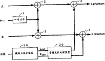
Shown in Figure 4, for being suitable for the example of above-mentioned Fig. 1, Fig. 2 or pseudo-stereophony device shown in Figure 3, it is signal with 4 sound channels behind the Dolby NR logical decode etc., promptly have 1 sound channel in 3 sound channels in the place ahead (left, center, right) rear (around) signal, although be 2 loud speakers (left speaker and right loud speaker) output from being provided with in listener the place ahead, just like from about listener the place ahead and the rear about amount to virtual stero set device like 4 loud speakers outputs.
1 sound channel export above-mentioned Fig. 1, Fig. 2 or pseudo-stereophony device 10 shown in Figure 3 to around (Surround) signal.Pseudo-stereophony device 10 generates analog loop around left signal L from 1 sound channel around signal
OUTAnd analog loop is around right signal R
OUT
This analog loop is around left signal L
OUTAnd analog loop is around right signal R
OUTDeliver to sound image localizing device 20.The signal L of 20 pairs of inputs of sound image localizing device
OUT, R
OUTCarry out audio-video localization process, make it signal L input
OUT, R
OUTThe back left that is positioned the listener is right-hand with the back.
On the other hand, to can 1 couple of central signal Cen-ter of multiplier carrying out-the adjusted signal of gain of 6dB, carry out left signal Left by adder 2 and add.For carrying out with 1 couple of central signal Center of multiplier-the adjusted signal of gain of 6dB, carry out right signal Right by adder 3 and add again.
The output of adder 2 with after the localization process of sound image localizing device 20 output around left signal L
OUT' add the back as output Lphantom by adder 4 to left speaker.Again, the output of adder 3 with after the localization process of sound image localizing device 20 output around right signal R
OUT' add the back as the output Rphantom of loud speaker to the right by adder 5.
Claims (3)
1. generate the pseudo-stereophony device of stereophonic signal by monophonic signal simulation ground, it is characterized in that having: be connected in series and m delayer of input signal S step delay;
Be output signal S with each delayer
k(k=1,2 ... m) carry out m Finite Impulse Response filter of Filtering Processing respectively; And
As with the output of each Finite Impulse Response filter as Y
k(k=1,2 ... m), then use the computing shown in the following formula (a), generate analog stereo signal L
OUT, R
OUTComputing circuit:
2. the described pseudo-stereophony device of claim 1 is characterized in that: with n
kAs the tap number of the Finite Impulse Response filter of K level, then the filter factor of each Finite Impulse Response filter satisfies the condition shown in the following formula (b):
3. pseudo-stereophony device according to claim 2 is characterized in that: between different Finite Impulse Response filters, and 2 multipliers that filter factor equates mutually, shared with 1 multiplier.
Applications Claiming Priority (2)
| Application Number | Priority Date | Filing Date | Title |
|---|---|---|---|
| JP216398 | 1998-01-08 | ||
| JP2163/1998 | 1998-01-08 |
Publications (2)
| Publication Number | Publication Date |
|---|---|
| CN1286011A CN1286011A (en) | 2001-02-28 |
| CN1134207C true CN1134207C (en) | 2004-01-07 |
Family
ID=11521701
Family Applications (1)
| Application Number | Title | Priority Date | Filing Date |
|---|---|---|---|
| CNB988129760A Expired - Fee Related CN1134207C (en) | 1998-01-08 | 1998-12-28 | Pseudo-stereophony device |
Country Status (9)
| Country | Link |
|---|---|
| US (1) | US6816597B1 (en) |
| EP (1) | EP1054576B1 (en) |
| JP (1) | JP3219752B2 (en) |
| KR (1) | KR100410793B1 (en) |
| CN (1) | CN1134207C (en) |
| AU (1) | AU1692699A (en) |
| DE (1) | DE69839736D1 (en) |
| TW (1) | TW411722B (en) |
| WO (1) | WO1999035886A1 (en) |
Families Citing this family (11)
| Publication number | Priority date | Publication date | Assignee | Title |
|---|---|---|---|---|
| JP3557177B2 (en) | 2001-02-27 | 2004-08-25 | 三洋電機株式会社 | Stereophonic device for headphone and audio signal processing program |
| US7451006B2 (en) | 2001-05-07 | 2008-11-11 | Harman International Industries, Incorporated | Sound processing system using distortion limiting techniques |
| US6804565B2 (en) | 2001-05-07 | 2004-10-12 | Harman International Industries, Incorporated | Data-driven software architecture for digital sound processing and equalization |
| EP1427104A4 (en) * | 2001-09-10 | 2006-11-29 | Yukio Koyanagi | Sound quality adjusting device and filter device used therefor, sound quality adjusting method, and filter designing method |
| JP4127156B2 (en) * | 2003-08-08 | 2008-07-30 | ヤマハ株式会社 | Audio playback device, line array speaker unit, and audio playback method |
| US7606374B2 (en) * | 2003-10-09 | 2009-10-20 | Yamaha Hatsudoki Kabushiki Kaisha | Engine sound synthesizer, motor vehicle and game machine employing the engine sound synthesizer, engine sound synthesizing method, and recording medium containing computer program for engine sound synthesis |
| JP4254502B2 (en) * | 2003-11-21 | 2009-04-15 | ヤマハ株式会社 | Array speaker device |
| KR100608025B1 (en) * | 2005-03-03 | 2006-08-02 | 삼성전자주식회사 | Method and apparatus for simulating virtual sound for two-channel headphones |
| US8340304B2 (en) | 2005-10-01 | 2012-12-25 | Samsung Electronics Co., Ltd. | Method and apparatus to generate spatial sound |
| US8955455B2 (en) * | 2010-01-29 | 2015-02-17 | Pioneer Corporation | Device and method for pseudonoise generation |
| US9276778B2 (en) * | 2014-01-31 | 2016-03-01 | Qualcomm Incorporated | Instruction and method for fused rake-finger operation on a vector processor |
Family Cites Families (4)
| Publication number | Priority date | Publication date | Assignee | Title |
|---|---|---|---|---|
| NL8303945A (en) * | 1983-11-17 | 1985-06-17 | Philips Nv | DEVICE FOR REALIZING A PSEUDO STEREO SIGNAL. |
| US5173944A (en) * | 1992-01-29 | 1992-12-22 | The United States Of America As Represented By The Administrator Of The National Aeronautics And Space Administration | Head related transfer function pseudo-stereophony |
| JPH07288896A (en) * | 1994-04-19 | 1995-10-31 | Sanyo Electric Co Ltd | Sound image controller |
| JPH09187100A (en) * | 1995-12-28 | 1997-07-15 | Sanyo Electric Co Ltd | Sound image controller |
-
1998
- 1998-12-04 TW TW087120128A patent/TW411722B/en active
- 1998-12-28 AU AU16926/99A patent/AU1692699A/en not_active Abandoned
- 1998-12-28 DE DE69839736T patent/DE69839736D1/en not_active Expired - Lifetime
- 1998-12-28 CN CNB988129760A patent/CN1134207C/en not_active Expired - Fee Related
- 1998-12-28 EP EP98961649A patent/EP1054576B1/en not_active Expired - Lifetime
- 1998-12-28 US US09/581,532 patent/US6816597B1/en not_active Expired - Fee Related
- 1998-12-28 KR KR10-2000-7007514A patent/KR100410793B1/en not_active IP Right Cessation
- 1998-12-28 JP JP2000528134A patent/JP3219752B2/en not_active Expired - Fee Related
- 1998-12-28 WO PCT/JP1998/006011 patent/WO1999035886A1/en active IP Right Grant
Also Published As
| Publication number | Publication date |
|---|---|
| AU1692699A (en) | 1999-07-26 |
| KR20010033932A (en) | 2001-04-25 |
| KR100410793B1 (en) | 2003-12-18 |
| JP3219752B2 (en) | 2001-10-15 |
| CN1286011A (en) | 2001-02-28 |
| US6816597B1 (en) | 2004-11-09 |
| WO1999035886A1 (en) | 1999-07-15 |
| EP1054576A4 (en) | 2006-04-05 |
| TW411722B (en) | 2000-11-11 |
| DE69839736D1 (en) | 2008-08-28 |
| EP1054576B1 (en) | 2008-07-16 |
| EP1054576A1 (en) | 2000-11-22 |
Similar Documents
| Publication | Publication Date | Title |
|---|---|---|
| CN101946526B (en) | Stereophonic widening | |
| CN1134207C (en) | Pseudo-stereophony device | |
| CN1625920A (en) | Audio apparatus and its reproduction program | |
| CN1942017A (en) | Apparatus and method to cancel crosstalk and stereo sound generation system using the same | |
| US8831254B2 (en) | Audio signal processing | |
| CA2496474A1 (en) | Bass management systems | |
| CN1863416B (en) | Audio device and method for generating surround sound | |
| CN101036414A (en) | Method of mixing audio channels using correlated outputs | |
| CN1947172A (en) | Method, device, encoder apparatus, decoder apparatus and frequency system | |
| CN1135904C (en) | Sound image localizing device | |
| CN1871874A (en) | Adaptive sound reproduction | |
| CN101552010B (en) | Audio treating method and audio treating device | |
| CN1829393A (en) | Method and apparatus to generate stereo sound for two-channel headphones | |
| CN1762178A (en) | Method for treating an electric sound signal | |
| CN1516520A (en) | Xiafula audible signal processing circuit, wave filter and method | |
| US20110026718A1 (en) | Virtualizer with cross-talk cancellation and reverb | |
| CN1237848C (en) | Headphone-use stereophonic device and voice signal processing program | |
| CN1129346C (en) | Method and device for producing multi-way sound channel from single sound channel | |
| CN1717124A (en) | Sound image localization apparatus | |
| CN101040322A (en) | A system and a method of processing audio data, a program element, and a computer-readable medium | |
| KR101785747B1 (en) | Method of optimizing stereo reception for analogue radio and associated analogue radio receiver | |
| CN101076959A (en) | Configurable filter for processing television audio signals | |
| CN1819720A (en) | Crosstalk eliminator and elimination thereof | |
| CN1791285A (en) | Signal processing method for dual-channel stereo signal stimulant 5.1 channel surround sound | |
| CN1794887A (en) | Audio processing method for enhancing three-dimensional |
Legal Events
| Date | Code | Title | Description |
|---|---|---|---|
| C06 | Publication | ||
| PB01 | Publication | ||
| C10 | Entry into substantive examination | ||
| SE01 | Entry into force of request for substantive examination | ||
| C14 | Grant of patent or utility model | ||
| GR01 | Patent grant | ||
| CF01 | Termination of patent right due to non-payment of annual fee |
Granted publication date: 20040107 Termination date: 20151228 |
|
| EXPY | Termination of patent right or utility model |