Spanner instrument that transmission line yoke plate was used
Technical Field
The invention relates to the field of power transmission line installation, in particular to a wrench tool for a power transmission line yoke plate.
Background
Traditional 66 kilovolt transmission line is after electrified fastening, installation yoke plate screw work, only with insulating sleeve pole fastening yoke plate screw, and whether firm through observing yoke plate gap, the fastening of spring pad roughness determination yoke plate screw, do not have unified numerical verification, consequently the inspection result is more inaccurate, leads to later stage transmission line to break down easily, in view of above problem, provides a wrench tool that transmission line yoke plate was used in particular.
Disclosure of Invention
The present invention is directed to a wrench tool for a power transmission line yoke plate, so as to solve the problems in the background art.
In order to achieve the purpose, the invention provides the following technical scheme: a wrench tool for a power transmission line yoke plate comprises a rotating device for mounting a screw structure, wherein a torque regulator for adjusting the maximum torque is assembled at the bottom end of the rotating device, an insulating rod is assembled at the bottom end of the torque regulator and comprises a rod body, a first inner screw pipe is integrally formed at the periphery of the top end of the rod body, a second inner screw pipe is integrally formed at the center of the rod body, the torque regulator comprises a supporting seat, an outer screw pipe is integrally formed at the periphery of the lower surface of the supporting seat, a screw rod is integrally formed at the lower surface of the center of the supporting seat, a fixing button is assembled between the screw rod and the gap of the outer screw pipe at the lower surface of the supporting seat, a hinge rod capable of being turned over is assembled at the bottom end of the fixing button, a stop block is welded on the outer surface of the hinge rod, and a positioning ring is welded on the inner surface of the outer screw pipe, the bottom internal surface of articulated mast has seted up the inclination, the bottom skin weld of screwed pipe has the gib block of slope in the second, the surface spiro union of outer screwed pipe is at the internal surface of first interior screwed pipe, the screw rod spiro union is at the internal surface of screwed pipe in the second, the gib block meshing is inboard at the inboard inclination of articulated mast bottom, the pitch of the screw thread that screw rod and outer screwed pipe surface were seted up is all the same in first interior screwed pipe, the second.
Preferably, the rotator comprises a transmission rod, the bottom end of the transmission rod is assembled at the top end of the torque adjuster, a transmission shaft structure is assembled inside the transmission rod, the bottom end of the transmission shaft structure is assembled at an output shaft of the torque adjuster, a wrench head is assembled at the top end of the transmission rod, a ratchet structure is assembled inside the wrench head, the bottom end of the ratchet structure is meshed with the top end of the transmission shaft structure through a gear transmission structure, a direction adjuster is assembled at the rear end of the ratchet structure penetrating through the rear end of the wrench head, and the direction adjuster can limit the allowable rotation direction of the ratchet structure.
Preferably, the front surface of the wrench head is provided with a clamping joint, the outer surface of the clamping joint is provided with a groove, and the outer surface of the groove is sleeved with a screw head anti-falling device for preventing the screw head from falling and losing.
Preferably, the spiral shell head anti-falling device includes the lantern ring, the bottom integrated into one piece of the lantern ring has the connecting wire, the front end integrated into one piece of connecting wire has the snap ring, the sealer that the elasticity rubber materials supported has been cup jointed on the top of snap ring, the left side assembly of sealer is on the top left side of snap ring.
Preferably, the top end of the support seat is provided with an adjuster, the inner surface of the adjuster is provided with an input rod, and the input rod is internally provided with a torsion limiter which passively rotates and gives a mechanical prompt sound when reaching a limit value.
Preferably, the outer surface of the rod body is uniformly and integrally formed with anti-skid grains.
Preferably, the outer surface of the top end of the supporting seat is integrally formed with an anti-slip block, and the outer surface of the regulator is uniformly provided with anti-slip grooves.
Preferably, the outer surface of the driving rod is equipped with an insulating skirt umbrella for preventing electric leakage of the circuit.
Compared with the prior art, the invention has the beneficial effects that: when the spanner is used, when a yoke plate screw needs to be installed or whether the yoke plate screw is fastened is detected, the adjuster is firstly rotated, different torque values are adopted according to the yoke plate screws with different specifications, the screw is continuously rotated after adjustment is completed, when the yoke plate screw does not achieve the fastening effect, the spanner can continuously drive the yoke plate screw to rotate, when the screw achieves the fastening torque, a screw head cannot continuously drive the screw to rotate, a snap spring structure in the torque adjuster passively jumps to make a sound, namely the yoke plate screw structure achieves the standard, and the problem that the existing method for detecting whether the yoke plate screw is fastened is inaccurate is effectively solved.
Drawings
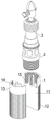
FIG. 1 is a schematic structural view of the present invention;
FIG. 2 is a sectional view of the insulating rod of the present invention;
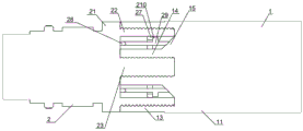
FIG. 3 is a schematic view of a cross-sectional configuration of the torque adjuster of the present invention;
FIG. 4 is a schematic cross-sectional view of an insulator spindle torque adjuster according to the present invention;
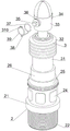
FIG. 5 is a schematic view of the wrench assembly of the present invention;
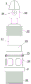
FIG. 6 is a schematic view of the wrench structure of the present invention;
FIG. 7 is a front view of the wrench structure of the present invention;
fig. 8 is a rear view of the wrench structure of the present invention.
In the figure: 1. the device comprises an insulating rod, 11, a rod body, 12, anti-skid threads, 13, a first inner screw pipe, 14, a second inner screw pipe, 15, a guide strip, 2, a torque regulator, 21, a supporting seat, 22, an outer screw pipe, 23, a screw rod, 24, an anti-skid block, 25, a regulator, 26, an input rod, 27, a positioning ring, 28, a fixing button, 29, a hinge rod, 210, a stop block, 3, a rotator, 31, a transmission rod, 32, an insulating skirt umbrella, 33, a wrench head, 34, a direction regulator, 35, a clamping joint, 36, a groove, 37, a sleeve ring, 38, a connecting wire, 39, a clamping ring, 310 and a sealing device.
Detailed Description
The technical solutions in the embodiments of the present invention will be clearly and completely described below with reference to the drawings in the embodiments of the present invention, and it is obvious that the described embodiments are only a part of the embodiments of the present invention, and not all of the embodiments. All other embodiments, which can be derived by a person skilled in the art from the embodiments given herein without making any creative effort, shall fall within the protection scope of the present invention.
Referring to fig. 1-8, the present invention provides a technical solution: a wrench tool for a power transmission line connecting plate comprises a rotator 3 for mounting a screw structure, a torque adjuster 2 for adjusting the maximum torque is assembled at the bottom end of the rotator 3, an insulating rod 1 is assembled at the bottom end of the torque adjuster 2, the insulating rod 1 comprises a rod body 11, a first inner screw pipe 13 is integrally formed at the periphery of the top end of the rod body 11, a second inner screw pipe 14 is integrally formed at the center of the rod body 11, the torque adjuster 2 comprises a supporting seat 21, an outer screw pipe 22 is integrally formed at the periphery of the lower surface of the supporting seat 21, a screw rod 23 is integrally formed at the lower surface of the center of the supporting seat 21, a fixing button 28 is assembled between a gap between the screw rod 23 and the outer screw pipe 22 at the lower surface of the supporting seat 21, a hinge rod 29 capable of being turned over is assembled at the bottom end of the fixing button 28, a stop block 210 is welded at the outer surface of the hinge rod 29, a positioning ring 27 is welded at the inner surface of the outer screw pipe 21, an inclined angle is formed in the inner surface of the bottom end of the hinged rod 29, an inclined guide strip 15 is welded on the outer surface of the bottom end of the second inner screw pipe 14, the outer surface of the outer screw pipe 22 is in threaded connection with the inner surface of the first inner screw pipe 13, the screw rod 23 is in threaded connection with the inner surface of the second inner screw pipe 14, the guide strip 15 is meshed on the inner side of the inclined angle of the inner side of the bottom end of the hinged rod 29, and the thread pitches of the threads formed on the outer surfaces of the first inner screw pipe 13, the second inner screw pipe 14, the screw rod 23 and the outer screw pipe 23 are the same.
The invention has set up a spanner with detection function with ratchet spanner structure and torque adjuster, while using, when needing to mount the yoke plate screw or detect the yoke plate screw is fastened, turn the adjuster 25 at first, according to the yoke plate screw of different specifications, adopt different torsion numerical value and after finishing regulating, turn the direction adjuster 34, make the passage direction of the ratchet be the fastening direction of the screw, then according to the size of the screw, rotate the appropriate screw head, the plug-in joint is on the external surface of the bayonet joint 35, and open the sealer 310, the snap ring 39 is cup jointed on the external surface of the screw head, then use the invention to continue to fasten the yoke plate screw, when the yoke plate screw does not reach the fastening effect, the spanner can continue to drive the yoke plate screw to rotate, when the screw reaches the fastening torsion, the screw head can't continue to drive the screw to rotate, and the force exerted on the exterior of passive insulating rod 1 will drive the ratchet structure relatively static to rotate continuously, and then the drive shaft structure is passively driven to rotate, and redundant force is transmitted to the interior of the torque regulator 2, and the torque regulator 2 reaches the maximum value, so that a clamp spring structure in the torque regulator passively jumps to make a sound, namely, a connecting plate screw structure reaches the standard, the problem that whether the existing connecting plate screw fastening checking method is inaccurate is effectively solved, and the connecting plate screw can be directly installed through the invention, and the set numerical value can reach a uniform installation effect during each installation, and the installation effect is uniform and reliable.
Specifically, the rotator 3 comprises a transmission rod 31, the bottom end of the transmission rod 31 is assembled at the top end of the torque adjuster 2, a transmission shaft structure is assembled inside the transmission rod 31, the bottom end of the transmission shaft structure is assembled at the output shaft of the torque adjuster 2, a wrench head 33 is assembled at the top end of the transmission rod 31, a ratchet structure is assembled inside the wrench head 33, the bottom end of the ratchet structure is meshed with the top end of the transmission shaft structure through a gear transmission structure, a direction adjuster 34 is assembled at the rear end of the ratchet structure penetrating through the rear end of the wrench head 33, and the direction adjuster 34 can limit the allowable rotation direction of the ratchet structure;
the direction regulator 34, the clamping joint 35 and the ratchet structure inside the ratchet wrench used in the invention are the same as the existing ratchet wrench in structure, and the only difference is that a shell is assembled outside the ratchet structure of the whole ratchet wrench, and the whole ratchet structure and the direction regulator can be combined into a whole, so when a screw is fastened, after the maximum fastening value is reached, redundant rotating force can passively overturn through the whole set of locked ratchet wrench, and the redundant force is transmitted to the inside of the torque regulator 2 through the rotation of the gear meshing transmission shaft on the outer surface of the shell, so that the purpose of detection is achieved.
Specifically, the front surface of wrench head 33 is equipped with joint 35, and recess 36 has been seted up to joint 35's surface, and the surface of recess 36 has cup jointed the spiral shell head anti falling device that is used for preventing the spiral shell head to take place to drop and lose.
The bayonet joint 35 structure is the screw head replacement structure that spanner was commonly used among the prior art, is equipped with the joint ball structure that is used for the location at the surface of joint pole, and the slot position that the joint corresponds in the screw head is inside when the screw head inserts and extracts, realizes being convenient for replace the purpose of different bore screw heads.
Specifically, the screw head anti-falling device comprises a sleeve ring 37, a connecting wire 38 is integrally formed at the bottom end of the sleeve ring 37, a snap ring 39 is integrally formed at the front end of the connecting wire 38, a sealing device 310 supported by elastic rubber materials is sleeved at the top end of the snap ring 39, and the left side of the sealing device 310 is assembled at the left side of the top end of the snap ring 39.
The outer surface of a screw head structure with a similar groove is sleeved with the bendable clamping ring 39 structure when the device is used, the sealing device 310 is used for sealing and positioning, and therefore the screw head can be prevented from falling and losing when the device is used, and the danger that the screw head falls when the device is used at high altitude is avoided.
Specifically, the top end of the supporting seat 21 is provided with the adjuster 25, the inner surface of the adjuster 25 is provided with the input rod 26, the input rod 26 is internally provided with the torque limiter, and the torque limiter passively rotates and sends out a mechanical prompt sound when reaching a limit value.
Specifically, the outer surface of the rod body 11 is uniformly and integrally formed with the anti-slip threads 12.
Specifically, the outer surface of the top end of the support base 21 is integrally formed with an anti-slip block 24, and the outer surface of the adjuster 25 is uniformly provided with anti-slip grooves.
Specifically, the outer surface of the transmission rod 31 is provided with an insulating skirt 32 for preventing electric leakage of the circuit, the insulating skirt 32 used in the present invention can prevent electric leakage of the wrench structure at the front end, and the insulating rod 1 and the torque adjuster have an electric leakage preventing function.
Because the mode that current insulator spindle and instrument are connected mostly adopts single spiral shell head and single screw spiro union to be connected, but the insulator spindle is not metal material at all, therefore structural strength is after having seted up the screw, the outer wall structural strength of screw can descend by a wide margin, consequently when insulator spindle 1 is connected with torque adjuster 2, can improve the stability of junction through two sets of spiro union structures inside and outside, and through the gib block 15 structure of slope, when the spiro union is on the end, push up the articulated mast 29 to the outside tightly, thereby lock dog 210 in the surface of holding ring 27, improve the stability of being connected between insulator spindle 1 and the torque adjuster 2, compare in the structure of current mode installation of single spiral shell head and screw spiro union location, stability is stronger, tensile effect is better.
The working principle is as follows: when the connecting plate screw is required to be installed or whether the connecting plate screw is fastened is detected, the regulator 25 is firstly rotated, different torsion values are adopted according to the connecting plate screws with different specifications and after regulation is finished, the direction regulator 34 is rotated, the passing direction of the ratchet wheel is the fastening direction of the screw, then a proper screw head is rotated according to the size of the screw, the screw head is inserted on the outer surface of the clamping head 35, the sealing device 310 is opened, the clamping ring 39 is sleeved on the outer surface of the screw head, then the connecting plate screw is continuously fastened by using the connecting plate screw fastening device, when the connecting plate screw does not achieve the fastening effect, the spanner can continuously drive the connecting plate screw to rotate, when the screw achieves the fastening torsion, the screw head cannot continuously drive the screw to rotate, and the force continuously applied to the outer part of the insulating rod 1 passively drives the relatively static ratchet wheel structure to integrally rotate, so as to passively drive the transmission shaft structure to rotate, and the redundant force is transmitted to the interior of the torque regulator 2, and the torque regulator 2 reaches the maximum value, so that the clamp spring structure in the torque regulator can passively jump to make a sound, namely the connection plate screw structure reaches the standard.
Although embodiments of the present invention have been shown and described, it will be appreciated by those skilled in the art that changes, modifications, substitutions and alterations can be made in these embodiments without departing from the principles and spirit of the invention, the scope of which is defined in the appended claims and their equivalents.