CN113412164B - Magnetic assembly and method for producing an optical effect layer comprising oriented, non-spherical, flat magnetic or magnetizable pigment particles - Google Patents
Magnetic assembly and method for producing an optical effect layer comprising oriented, non-spherical, flat magnetic or magnetizable pigment particles Download PDFInfo
- Publication number
- CN113412164B CN113412164B CN202080013224.XA CN202080013224A CN113412164B CN 113412164 B CN113412164 B CN 113412164B CN 202080013224 A CN202080013224 A CN 202080013224A CN 113412164 B CN113412164 B CN 113412164B
- Authority
- CN
- China
- Prior art keywords
- magnetic
- magnetic field
- field generating
- dipole magnets
- generating means
- Prior art date
- Legal status (The legal status is an assumption and is not a legal conclusion. Google has not performed a legal analysis and makes no representation as to the accuracy of the status listed.)
- Active
Links
Images


Classifications
-
- B—PERFORMING OPERATIONS; TRANSPORTING
- B42—BOOKBINDING; ALBUMS; FILES; SPECIAL PRINTED MATTER
- B42D—BOOKS; BOOK COVERS; LOOSE LEAVES; PRINTED MATTER CHARACTERISED BY IDENTIFICATION OR SECURITY FEATURES; PRINTED MATTER OF SPECIAL FORMAT OR STYLE NOT OTHERWISE PROVIDED FOR; DEVICES FOR USE THEREWITH AND NOT OTHERWISE PROVIDED FOR; MOVABLE-STRIP WRITING OR READING APPARATUS
- B42D25/00—Information-bearing cards or sheet-like structures characterised by identification or security features; Manufacture thereof
- B42D25/30—Identification or security features, e.g. for preventing forgery
- B42D25/36—Identification or security features, e.g. for preventing forgery comprising special materials
- B42D25/369—Magnetised or magnetisable materials
-
- B—PERFORMING OPERATIONS; TRANSPORTING
- B05—SPRAYING OR ATOMISING IN GENERAL; APPLYING FLUENT MATERIALS TO SURFACES, IN GENERAL
- B05D—PROCESSES FOR APPLYING FLUENT MATERIALS TO SURFACES, IN GENERAL
- B05D3/00—Pretreatment of surfaces to which liquids or other fluent materials are to be applied; After-treatment of applied coatings, e.g. intermediate treating of an applied coating preparatory to subsequent applications of liquids or other fluent materials
- B05D3/20—Pretreatment of surfaces to which liquids or other fluent materials are to be applied; After-treatment of applied coatings, e.g. intermediate treating of an applied coating preparatory to subsequent applications of liquids or other fluent materials by magnetic fields
- B05D3/207—Pretreatment of surfaces to which liquids or other fluent materials are to be applied; After-treatment of applied coatings, e.g. intermediate treating of an applied coating preparatory to subsequent applications of liquids or other fluent materials by magnetic fields post-treatment by magnetic fields
-
- B—PERFORMING OPERATIONS; TRANSPORTING
- B05—SPRAYING OR ATOMISING IN GENERAL; APPLYING FLUENT MATERIALS TO SURFACES, IN GENERAL
- B05D—PROCESSES FOR APPLYING FLUENT MATERIALS TO SURFACES, IN GENERAL
- B05D5/00—Processes for applying liquids or other fluent materials to surfaces to obtain special surface effects, finishes or structures
- B05D5/06—Processes for applying liquids or other fluent materials to surfaces to obtain special surface effects, finishes or structures to obtain multicolour or other optical effects
- B05D5/065—Processes for applying liquids or other fluent materials to surfaces to obtain special surface effects, finishes or structures to obtain multicolour or other optical effects having colour interferences or colour shifts or opalescent looking, flip-flop, two tones
-
- B—PERFORMING OPERATIONS; TRANSPORTING
- B42—BOOKBINDING; ALBUMS; FILES; SPECIAL PRINTED MATTER
- B42D—BOOKS; BOOK COVERS; LOOSE LEAVES; PRINTED MATTER CHARACTERISED BY IDENTIFICATION OR SECURITY FEATURES; PRINTED MATTER OF SPECIAL FORMAT OR STYLE NOT OTHERWISE PROVIDED FOR; DEVICES FOR USE THEREWITH AND NOT OTHERWISE PROVIDED FOR; MOVABLE-STRIP WRITING OR READING APPARATUS
- B42D25/00—Information-bearing cards or sheet-like structures characterised by identification or security features; Manufacture thereof
- B42D25/30—Identification or security features, e.g. for preventing forgery
- B42D25/36—Identification or security features, e.g. for preventing forgery comprising special materials
- B42D25/364—Liquid crystals
-
- B—PERFORMING OPERATIONS; TRANSPORTING
- B42—BOOKBINDING; ALBUMS; FILES; SPECIAL PRINTED MATTER
- B42D—BOOKS; BOOK COVERS; LOOSE LEAVES; PRINTED MATTER CHARACTERISED BY IDENTIFICATION OR SECURITY FEATURES; PRINTED MATTER OF SPECIAL FORMAT OR STYLE NOT OTHERWISE PROVIDED FOR; DEVICES FOR USE THEREWITH AND NOT OTHERWISE PROVIDED FOR; MOVABLE-STRIP WRITING OR READING APPARATUS
- B42D25/00—Information-bearing cards or sheet-like structures characterised by identification or security features; Manufacture thereof
- B42D25/40—Manufacture
- B42D25/405—Marking
-
- H—ELECTRICITY
- H01—ELECTRIC ELEMENTS
- H01F—MAGNETS; INDUCTANCES; TRANSFORMERS; SELECTION OF MATERIALS FOR THEIR MAGNETIC PROPERTIES
- H01F7/00—Magnets
- H01F7/02—Permanent magnets [PM]
- H01F7/0273—Magnetic circuits with PM for magnetic field generation
Abstract
The present invention relates to the field of magnetic assemblies and methods for producing Optical Effect Layers (OEL) on a substrate, said Optical Effect Layers (OEL) comprising magnetically oriented non-spherical, flat-shaped magnetic or magnetizable pigment particles. In particular, the present invention relates to magnetic assemblies and methods for producing said OEL as an anti-counterfeiting means on security documents or security articles or for decorative purposes.
Description
Technical Field
The present invention relates to the field of protecting documents of value and commercial goods of value or brand against counterfeiting and illicit reproduction. In particular, the present invention relates to a method for producing an Optical Effect Layer (OEL) exhibiting a viewing angle dynamic appearance, to the optical effect layer, and to the use of said OEL as an anti-counterfeiting means on documents and articles.
Background
The production of security elements and security documents using inks, coating compositions, coating films or layers comprising magnetic or magnetizable pigment particles, in particular non-spherical optically variable magnetic or magnetizable pigment particles, is known in the prior art.
Security features for security documents and articles may be classified as "covert" and "overt" security features. The protection provided by covert security features relies on the notion that such features are hidden to the human senses, typically requiring their detection with specialized instruments and knowledge, while "overt" security features can be readily detected with independent (unaided) human senses. Such features may be visible and/or detectable by touch, but still difficult to produce and/or reproduce. However, the effectiveness of overt security features is largely dependent on their ease of identification as security features, since a user, if aware of its presence and nature, will actually only perform security checks based on such security features.
Coating films or layers comprising oriented magnetic or magnetizable pigment particles are disclosed in, for example, US 2,570,856; US 3,676,273; US 3,791,864; US 5,630,877 and US 5,364,689. The magnetic or magnetizable pigment particles in the coating film are able to produce magnetically induced images, designs and/or patterns by applying a corresponding magnetic field, resulting in a local alignment of the magnetic or magnetizable pigment particles in the unhardened coating film, followed by hardening of the unhardened coating film, thereby fixing the particles in their position and orientation. This results in a specific optical effect, i.e. a fixed magnetically induced image, design or pattern that is highly resistant to counterfeiting. Security elements based on oriented magnetic or magnetizable pigment particles can only be produced by simultaneously utilizing magnetic or magnetizable pigment particles or a corresponding ink or coating composition comprising said particles and a specific technique for applying the ink or coating composition and for orienting the pigment particles in the applied ink or coating composition, followed by hardening the ink or composition.
A particularly prominent optical effect can be achieved if the security feature changes its appearance when viewing conditions, such as viewing angle, change. One example is the so-called "rolling-bar" effect as disclosed in US 2005/0106367. The "rolling bar" effect (fig. 1A) is based on simulating pigment particle orientation across the curved surface of a coating film. The observer sees the region of specular reflection, which moves away from or towards the observer as the security feature is tilted. So-called positive rolling bars comprise pigment particles oriented in a concave manner (fig. 1C) and follow a positively curved surface; the positive rolling bar moves with the sense of rotation of the tilt. A so-called negative rolling bar comprises pigment particles oriented in a convex manner (fig. 1B) and follows a negative curve; the negative roll bar moves against the sense of rotation of the tilt. The hardened coating film containing pigment particles oriented following the concave curvature (positive curve orientation) shows a visual effect characterized in that the rolling bar moves upward (positive rolling bar) when the support is tilted backward. The concave curvature is a curvature seen by an observer viewing the cured coating film from the side of the support on which the cured coating film is supported (fig. 1C). The hardened coating film containing pigment particles oriented to follow a convex curvature (negative curve orientation, fig. 1B) shows a visual effect characterized in that the rolling bar moves downward (negative rolling bar) when the support bearing the hardened coating film is tilted backward (i.e., the top of the support moves away from the viewer and the bottom of the support moves toward the viewer) (fig. 1A). Today, this effect is used for many security elements on banknotes, for example on "5" and "10" of 5 euro and 10 euro banknotes respectively.
Another example of a security feature with a dynamic optical effect is disclosed in WO 2018/045233 A1, wherein the dynamic effect exhibits a band of light reflected from magnetically oriented pigment particles that move when the feature is tilted. WO 2018/045233 A1 discloses dynamic optical effects where a band of light is reflected, the movement occurring in a direction perpendicular to the direction of the feature inclination. The dynamic optical effect disclosed in WO 2018/045233 A1 is referred to as an orthogonal-parallax optical effect (orthonormal optical effect). The orthogonal parallax optical effect can be described as an optical effect as follows: where an optical feature, such as a band that appears brighter or darker than other portions of the security feature, appears to move across the security feature in a direction orthogonal to the direction of inclination of the security feature. Thus, for example, when the security feature is tilted sideways (e.g. about a latitudinal axis), the optical feature may appear to move in a longitudinal direction. WO 2018/045230 A1 further discloses an apparatus and method for orienting magnetic flakes to produce a security feature on a substrate that exhibits orthogonal parallax optical effects, wherein the magnetically orientable flakes are subjected to a magnetic field and fixed in a desired orientation by using a mask comprising at least one opening, wherein the mask and the at least one opening can be strategically positioned relative to the magnetic field such that the magnetically orientable flakes are fixed by a radiation source at a desired dihedral angle relative to the substrate.
There remains a need for magnetic assemblies and methods for producing Optical Effect Layers (OELs) based on oriented magnetic or magnetizable pigment particles in an ink or coating composition, wherein the magnetic assemblies and methods are reliable, easy to implement and capable of operating at high production speeds, while allowing the production of OELs exhibiting attractive orthotropic effects and are difficult to mass produce using equipment available to counterfeiters.
Disclosure of Invention
It is therefore an object of the present invention to provide a magnetic assembly (x 00) for producing an Optical Effect Layer (OEL) on a surface of a substrate (x 20), the Optical Effect Layer (OEL) exhibiting an orthogonal parallax effect, and the assembly (x 00) comprising:
a) A first magnetic field generating means (x 30) comprising n sets of spaced apart rod-shaped dipole magnets (x 31), preferably n sets of 2 or more spaced apart rod-shaped dipole magnets (x 31), n being an integer equal to or greater than 1,
wherein the respective north and south magnetic axes of the bar-shaped dipole magnets (x 31) are substantially parallel to the surface of the base material (x 20),
wherein, for each of the n groups, the north poles of the bar-shaped dipole magnets (x 31) point in the same direction and are substantially parallel to each other, and
wherein the rod-shaped dipole magnets (x 31) of the first magnetic field generating means (x 30) are at least partially or completely embedded in a polygonal supporting matrix (x 32), and
b) A second magnetic field generating means (x 40) comprising 1 or more square or rectangular dipole magnets (x 41), the north-south magnetic axes of the square or rectangular dipole magnets (x 41) being substantially parallel to the surface of the substrate (x 20);
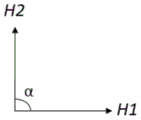
wherein the vector sum H1 of the magnetic axes of the bar-shaped dipole magnets (x 31) of the first magnetic field generating means (x 30) forms an angle a with the vector sum H2 of the 1 or more square or rectangular dipole magnets (x 41), said angle a being in the range of about 5 ° to about 175 ° or in the range of about 185 ° to about 355 °, preferably in the range of about 60 ° to about 120 ° or in the range of about 240 ° to about 300 °.
The first magnetic field generating device (x 30) described herein is placed below or above the second magnetic field generating device (x 40) described herein.
The first magnetic field generating means (x 30) described herein and the second magnetic field generating means (x 40) described herein may be substantially concentric with each other.
Also described herein is the use of the magnetic component (x 00) described herein for producing an Optical Effect Layer (OEL) on a substrate.
Also described herein are: a printing apparatus comprising a rotating magnetic cylinder comprising at least one magnetic assembly (x 00) as described herein; and a printing apparatus comprising a flatbed printing unit comprising at least one magnetic component (x 00) as described herein, wherein the printing apparatus is suitable for producing an Optical Effect Layer (OEL) as described herein on a substrate, such as those described herein. Also described herein is the use of the printing apparatus described herein for producing the Optical Effect Layers (OEL) described herein on a substrate, such as those described herein.
Also described herein are methods for producing the Optical Effect Layers (OEL) described herein on a substrate (x 20), said OEL exhibiting an orthogonal parallax effect, and the OEL obtained thereby. The method comprises the following steps:
i) Applying a radiation curable coating composition comprising non-spherical platy magnetic or magnetizable pigment particles on a surface of a substrate (x 20) so as to form a coating (x 10), the radiation curable coating composition being in a first state;
ii) exposing the radiation curable coating composition to the magnetic field of a static magnetic component (x 00) as described herein, so as to orient at least a portion of the non-spherical platy magnetic or magnetizable pigment particles; and
iii) At least partially curing the radiation curable coating composition of step ii) to a second state so as to fix the non-spherical platy magnetic or magnetizable pigment particles in the position or orientation they adopt.
Also described herein are methods of manufacturing a security document or decorative element or object comprising a) providing a security document or decorative element or object, and b) providing an Optical Effect Layer (OEL) such as those described herein, in particular such as those obtained by the methods described herein, such that it is comprised by the security document or decorative element or object.
Drawings
Fig. 1A schematically illustrates the "rolling bar" effect, and fig. 1B-C schematically illustrate the pigment particle orientation of the "rolling bar" effect (negative rolling bar in fig. 1B and positive rolling bar in fig. 1C) on the substrate (S).
2A-C schematically illustrate a magnetic assembly (200) for producing an Optical Effect Layer (OEL) on a surface of a substrate (220), wherein the magnetic assembly (200) comprises a first magnetic field generating means (230), the first magnetic field generating means (230) comprising 1 set of 2 spaced apart rod-shaped dipole magnets (231-a 1, 231-a 2); and a second magnetic field generating means (240) comprising a square dipole magnet (241), wherein the first magnetic field generating means (230) is placed below the second magnetic field generating means (240) and both are substantially concentric with each other. The magnetic axes of the 2 bar-shaped dipole magnets (231-a 1, 231-a 2) are substantially parallel to the surface of the base material (220), substantially parallel to each other and embedded in a square support matrix (232).
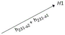
Fig. 2D1 to D3 schematically illustrate vectors of the magnetic axes of the 2 rod-shaped dipole magnets (231-a 1, 231-a 2) of the first magnetic field generating device (230) and the vector sum H1. Fig. 2D-3 illustrates an angle α between the vector sum H1 of the magnetic axes of the rod-shaped dipole magnets (231-a 1, 231-a 2) and the vector sum H2 of the square dipole magnet (241) of the first magnetic field generation device (230).
Fig. 2E shows pictures of OEL obtained by using the magnetic assembly (200) shown in fig. 2A-D, as viewed from a fixed position as the sample is tilted from-20 ° to +20 °.
Fig. 3A-C schematically illustrate a magnetic assembly (300) for producing an Optical Effect Layer (OEL) on a surface of a substrate (320), wherein the magnetic assembly (300) comprises a first magnetic field generating means (330), the first magnetic field generating means (330) comprising 1 set of 2 spaced apart rod-shaped dipole magnets (331-a 1, 331-a 2); a second magnetic field generating means (340) comprising a square dipole magnet (341); and a square pole piece (350), wherein the first magnetic field generating device (330) is placed below the second magnetic field generating device (340), wherein the square pole piece (350) is placed below the first magnetic field generating device (330), and wherein the first magnetic field generating device (330), the second magnetic field generating device (340), and the square pole piece (350) are substantially concentric with each other. The magnetic axes of the 2 bar-shaped dipole magnets (331-a 1, 331-a 2) are substantially parallel to the surface of the base material (320), substantially parallel to each other and embedded in a square support base (332).
Fig. 3D1 to D3 schematically illustrate the vector of the magnetic axes of the 2 rod-shaped dipole magnets (331-a 1, 331-a 2) of the first magnetic field generating means (330) and the vector sum H1. Fig. 3D-3 illustrates an angle α between the vector sum H1 of the magnetic axes of the bar-shaped dipole magnets (331-a 1, 331-a 2) and the vector sum H2 of the square dipole magnet (341) of the first magnetic field generating means (330).
Fig. 3E shows a picture of the OEL obtained by using the magnetic assembly (300) shown in fig. 3A-D, as viewed from a fixed position as the sample is tilted from-20 ° to +20 °.
FIGS. 4A-C schematically illustrate a magnetic assembly (400) for producing an Optical Effect Layer (OEL) on a surface of a substrate (420), wherein the magnetic assembly (400) comprises a first magnetic field generating means (430), the first magnetic field generating means (430) comprising 2 sets of 2 spaced apart rod-like dipole magnets (first set: 431-a1 and 431-a2; second set: 431-b1 and 431-b 2); and a second magnetic field generating means (440) comprising a square dipole magnet (441), wherein the first magnetic field generating means (430) is placed below the second magnetic field generating means (440) and both are substantially concentric with each other. The magnetic axes of the 4 bar-shaped dipole magnets (431-a 1, 431-a2, 431-b1, 431-b 2) are substantially parallel to the base material (420), and are embedded in a square support matrix (432) and arranged in a square shape. The 2 bar-shaped dipole magnets (431-a 1, 431-a 2) of the first group are substantially parallel to each other, and the 2 bar-shaped dipole magnets (431-b 1, 431-b 2) of the second group are substantially parallel to each other.
Fig. 4D1-D3 schematically illustrate vectors of magnetic axes of the 4 rod-shaped dipole magnets (431-a 1, 431-a2, 431-b1, 431-b 2) of the first magnetic field generating means (430) and the vector sum H1. Fig. 4D-3 illustrates an angle α between the vector sum H1 of the magnetic axes of the rod-shaped dipole magnets (431-a 1, 431-a2, 431-b1, 431-b 2) and the vector sum H2 of the square dipole magnet (441) of the first magnetic field generating means (430).
Fig. 4E shows pictures of OEL obtained by using the magnetic assembly (400) shown in fig. 4A-D, as viewed from a fixed position as the sample is tilted from-20 ° to +60 °.
FIGS. 5A-C schematically illustrate a magnetic assembly (500) for producing an Optical Effect Layer (OEL) on a surface of a substrate (520), wherein the magnetic assembly (500) comprises a first magnetic field generating means (530), the first magnetic field generating means (530) comprising 2 sets of 2 spaced apart rod-like dipole magnets (first set: 531-a1 and 531-a2; second set: 531-b1 and 531-b 2); and a second magnetic field generating means (540) comprising square dipole magnets (541), wherein the first magnetic field generating means (530) is positioned below the second magnetic field generating means (540) and both are substantially concentric with each other. The magnetic axes of the 4 bar-shaped dipole magnets (531-a 1, 531-a2, 531-b1, 531-b 2) are substantially parallel to the base (520), embedded in a square support base (532), and arranged in a rhombus shape. The first set of 2 rod-shaped dipole magnets (531-a 1, 531-a 2) are substantially parallel to each other, and the second set of 2 rod-shaped dipole magnets (531-b 1, 531-b 2) are substantially parallel to each other.
Fig. 5D1 to D3 schematically illustrate vectors of magnetic axes of the 4 bar-shaped dipole magnets (531-a 1, 531-a2, 531-b1, 531-b 2) of the first magnetic field generating device (530) and the vector sum H1. Fig. 5D-3 illustrates an angle α between the vector sum H1 of the magnetic axes of the bar-shaped dipole magnets (531-a 1, 531-a2, 531-b1, 531-b 2) and the vector sum H2 of the square dipole magnet (541) of the first magnetic field generating means (530).
Fig. 5E shows a picture of the OEL obtained by using the magnetic assembly (500) shown in fig. 5A-D, as viewed from a fixed position as the sample is tilted from-20 ° to +60 °.
Detailed Description
Definition of
The following definitions are set forth to clarify the meaning of the terms used in the specification and recited in the claims.
As used herein, the indefinite article "a" means one and greater than one, and does not necessarily limit its designated noun to be singular.
As used herein, the term "about" means that the amount or value in question may be at or near the specified value. Generally, the term "about" denoting a particular value is intended to mean a range within ± 5% of that value. As one example, the phrase "about 100" means a range of 100 ± 5, i.e., a range from 95 to 105. In general, when the term "about" is used, it is contemplated that similar results or effects according to the present invention may be obtained within a range of ± 5% of the specified value.
The term "substantially parallel" means no more than 10 ° from parallel alignment and the term "substantially perpendicular" means no more than 10 ° from perpendicular alignment.
As used herein, the term "and/or" means that two or only one of the elements connected by the term are present. For example, "a and/or B" shall mean "only a, or only B, or both a and B". In the case of "a only", the term also covers the possibility that B is absent, i.e. "a only, but no B".
The term "comprising" as used herein is intended to be non-exclusive and open-ended. Thus, for example, a solution composition comprising compound a may comprise other compounds than a. However, the term "comprising" also covers as specific embodiments thereof the more restrictive meaning of "consisting essentially of 8230; …" consisting of 8230; 〓 "consisting of 8230, so that, for example," a composition comprising A, B, and optionally C "may also consist either (essentially) of A and B, or (essentially) of A, B, and C.
The term "coating composition" refers to any composition capable of forming a coating film, in particular an Optical Effect Layer (OEL) as described herein, on a solid substrate and which may preferably, but not exclusively, be applied by a printing process. The coating compositions described herein comprise at least a plurality of non-spherical platy magnetic or magnetizable pigment particles and a binder.
The term "optical effect layer" (OEL) as used herein means a layer comprising at least a plurality of magnetically oriented non-spherical platy magnetic or magnetizable pigment particles and a binder, wherein the non-spherical platy magnetic or magnetizable pigment particles are fixed or frozen (fixed/frozen) in their position and orientation within the binder.
In the context of the present disclosure, "pigment particles" designate particulate materials that are insoluble in the ink or coating composition and impart a defined spectral transmission/reflection response to the ink or coating composition.
The term "magnetic direction" denotes the direction of the magnetic field vector along the magnetic field lines that point from their north poles to their south poles outside the magnet (see Handbook of Physics, springer 2002, pages 463-464).
The term "make \8230; curing (curing)" means a method as follows: the viscosity of the coating composition increases in response to the stimulus, thereby converting the coating composition into a state (i.e., a cured, hardened, or solid state) in which the magnetic or magnetizable pigment particles contained therein are fixed/frozen in their position and orientation and are no longer able to move or rotate.
As used herein, the term "at least" defines a determined amount or more than that amount, e.g., "at least one" means one or two or three, etc.
The term "security document" refers to a document that is protected from counterfeiting or fraud by at least one security feature. Examples of security documents include, without limitation, currency, documents of value, and identity documents, among others.
The term "security feature" means an overt or covert image, pattern or graphic element that can be used to authenticate (authentication) the document or article carrying it.
Where the present description refers to "preferred" embodiments/features, combinations of these "preferred" embodiments/features should also be considered disclosed as preferred, as long as this combination of "preferred" embodiments/features is technically meaningful.
The present invention provides a magnetic component (x 00) and a method of using the magnetic component (x 00) suitable for producing an Optical Effect Layer (OEL), the OEL comprising a plurality of non-randomly oriented, non-spherical, flat-shaped magnetic or magnetizable pigment particles, said pigment particles being dispersed within a hardened/cured material; and an Optical Effect Layer (OEL) obtained therefrom. Due to the orientation pattern of the magnetic or magnetizable pigment particles, the optical OEL described herein provides the visual impression of an orthogonal parallax effect, i.e. in the form of in the present case brightly reflective vertical bars that move in the longitudinal direction when the substrate carrying the OEL is tilted around a transverse/latitudinal axis or in the horizontal/latitudinal direction when the substrate carrying the OEL is tilted around a longitudinal axis.
The present invention provides a process and a method for producing an Optical Effect Layer (OEL) as described herein on a substrate as described herein, and an Optical Effect Layer (OEL) obtained therefrom, wherein the method comprises: step i) applying a radiation curable coating composition comprising the non-spherical platy magnetic or magnetizable pigment particles described herein on a surface of a substrate, the radiation curable coating composition being in a first state, i.e., a liquid or paste state, wherein the radiation curable coating composition is wet or sufficiently soft that the non-spherical platy magnetic or magnetizable pigment particles dispersed in the radiation curable coating composition are freely movable, rotatable and/or orientable upon exposure to a magnetic field.
Step i) described herein may be performed by a coating method such as a roll coating method and a spray coating method, or by a printing method. Preferably, step i) described herein is performed by a printing method, preferably selected from the group consisting of screen printing (screen printing), rotogravure printing, flexographic printing, ink jet printing and intaglio printing (also known in the art as engraved copperplate printing and engraved steel die printing), more preferably selected from the group consisting of screen printing, rotogravure printing and flexographic printing.
In connection with applying the radiation curable coating composition described herein on the surface of the substrate described herein (step i)), partially simultaneously or simultaneously, at least a portion of the non-spherical platy magnetic or magnetizable pigment particles are oriented by exposing the radiation curable coating composition to the magnetic component described herein (x 00) and a static magnetic field (step ii)), thereby aligning at least a portion of the non-spherical platy magnetic or magnetizable pigment particles along the magnetic field lines generated by the component (x 00).
The orientation of the non-spherical platy magnetic or magnetizable pigment particles is fixed or frozen directly or partially simultaneously with the step of orienting/aligning at least a portion of the non-spherical platy magnetic or magnetizable pigment particles by applying the magnetic field described herein. The radiation-curable coating composition must therefore notably have a first state, i.e. a liquid or paste state, in which the radiation-curable coating composition is wet or sufficiently soft that the non-spherical platy magnetic or magnetizable pigment particles dispersed in the radiation-curable coating composition are freely movable, rotatable and/or orientable when exposed to a magnetic field; and has a second, cured (e.g., solid) state in which the non-spherical, flat-shaped magnetic or magnetizable pigment particles are fixed or frozen in their respective positions and orientations.
Accordingly, a method for producing an Optical Effect Layer (OEL) on a substrate described herein comprises: step iii) at least partially curing the radiation curable coating composition of step ii) to a second state to fix the non-spherical platy magnetic or magnetizable pigment particles in the position and orientation they adopt. Step iii) of at least partially curing the radiation curable coating composition may be performed indirectly or partially simultaneously with the step (step ii)) of orienting/aligning at least a portion of the non-spherical platy magnetic or magnetizable pigment particles by applying the magnetic field described herein. Preferably, step iii) of at least partially curing the radiation curable coating composition is performed partially simultaneously with the step (step ii)) of orienting/aligning at least a portion of the non-spherical platy magnetic or magnetizable pigment particles by applying the magnetic field described herein. By "partially simultaneously", it is meant that the two steps are performed partially simultaneously, i.e. the times at which the respective steps are performed partially overlap. In the context of the description herein, when curing is performed partially simultaneously with the orientation step ii), it must be understood that curing becomes effective after orientation, so that the pigment particles have time to orient before the OEL is fully or partially cured or hardened.
The first and second states of the radiation curable coating composition are provided by using a particular type of radiation curable coating composition. For example, the components of the radiation curable coating composition other than the non-spherical platy magnetic or magnetizable pigment particles may take the form of inks or radiation curable coating compositions, such as those used in security applications such as banknote printing. The aforementioned first and second states are provided by using a material that shows an increase in viscosity in a reaction to exposure to electromagnetic radiation. That is, when the fluid binder material cures or solidifies, the binder material transitions to a second state in which the non-spherical, flat-shaped magnetic or magnetizable pigment particles are fixed in their current position and orientation and are no longer able to move or rotate within the binder material.
As known to those skilled in the art, the ingredients included in the radiation curable coating composition to be applied to a surface, such as a substrate, and the physical properties of the radiation curable coating composition must meet the requirements of the method for transferring the radiation curable coating composition to the surface of the substrate. Thus, the binder material comprised in the radiation curable coating composition described herein is typically selected from those known in the art and depends on the coating or printing process used to apply the radiation curable coating composition and the selected radiation curing process.
In the Optical Effect Layer (OEL) described herein, the non-spherical flat magnetic or magnetizable pigment particles described herein are dispersed in a cured/hardened radiation curable coating composition comprising a cured binder material that fixes/freezes the orientation of the magnetic or magnetizable pigment particles. The cured binder material is at least partially transparent to electromagnetic radiation in a wavelength range comprised between 200nm and 2500 nm. Thus, the binder material is at least in its cured or solid state (also referred to herein as the second state) at least partially transparent to electromagnetic radiation in a wavelength range comprised between 200nm and 2500nm, i.e. in a wavelength range typically referred to as the "spectrum" and comprising the infrared, visible and UV portions of the electromagnetic spectrum, such that the particles and their orientation-dependent reflectance (orientation-dependent reflectance) contained in the binder material in its cured or solid state can be perceived through the binder material. Preferably, the cured binder material is at least partially transparent to electromagnetic radiation of a wavelength range comprised between 200nm and 800nm, more preferably comprised between 400nm and 700 nm. Herein, the term "transparent" means that the transmission of electromagnetic radiation through a 20 μm layer of cured binder material (excluding platelet-shaped magnetic or magnetizable pigment particles, but including all other optional components of the OEL in the presence of such components) present in the OEL is at least 50%, more preferably at least 60%, even more preferably at least 70%, at the wavelength or wavelengths of interest. This can be determined, for example, by measuring the transmittance of test pieces of cured binder material (excluding non-spherical, flat magnetic or magnetizable pigment particles) according to well-established test methods, such as DIN 5036-3 (1979-11). If OEL is used as a covert security feature, typical technical means would be necessary to detect the (complete) optical effect produced by OEL under various lighting conditions including selected invisible wavelengths; the detection requires that the wavelength of the incident radiation is selected to be outside the visible range, for example in the near UV range. The infrared, visible and UV portions of the electromagnetic spectrum correspond approximately to the wavelength ranges between 700-2500nm, between 400-700nm and between 200-400nm, respectively.
As noted above, the radiation curable coating compositions described herein depend on the coating or printing process used to apply the radiation curable coating composition and the selected curing process. Preferably, curing of the radiation curable coating composition involves chemical reactions that would occur in typical use of articles comprising OELs described herein, which are not reversed by a simple temperature increase (e.g., up to 80 ℃). The term "curing" or "curability" refers to a process comprising a chemical reaction, crosslinking, or polymerization of at least one component of an applied radiation curable coating composition in a manner that it converts to a high molecular material having a larger molecular weight than the starting materials. Radiation curing advantageously results in a transient increase in the viscosity of the radiation curable coating composition after exposure to curing radiation, thereby preventing any further movement of the pigment particles and thus preventing any loss of information after the magnetic orientation step. Preferably, the curing step (step iii)) is performed by radiation curing including UV-visible radiation curing or by electron beam radiation curing, more preferably by UV-visible radiation curing.
Accordingly, suitable radiation-curable coating compositions of the present invention include radiation-curable compositions that are curable by UV-visible radiation (hereinafter referred to as UV-Vis radiation) or by electron beam radiation (hereinafter referred to as EB radiation). Radiation curable compositions are known in the art and can be queried in standard textbooks such as the series "Chemistry & Technology of UV & EB Formulation for Coatings, inks & paintings", volume IV, formulation, C.Lowe, G.Webster, S.Kessel and I.McDonald,1996, john Wiley &sonsin combination with SITA Technology Limited. According to a particularly preferred embodiment of the present invention, the radiation curable coating composition described herein is a UV-Vis radiation curable coating composition. Thus, the radiation curable coating composition comprising the non-spherical platy magnetic or magnetizable pigment particles described herein is preferably cured at least in part by UV-Vis light radiation, preferably by LED light of Sup>A narrow bandwidth in the UV-Sup>A (315-400 nm) or blue (400-500 nm) spectral region, most preferably by Sup>A powerful LED source emitting in the 350nm to 450nm spectral region, with Sup>A typical emission bandwidth in the 20nm to 50nm range. UV radiation from mercury vapor lamps or doped mercury lamps can also be used to increase the cure speed of radiation curable coating compositions.
Preferably, the UV-Vis radiation curable coating composition comprises one or more compounds selected from the group consisting of radical curable compounds and cationic curable compounds. The UV-Vis radiation curable coating composition described herein may be a mixed system (hybrid system) and include a mixture of one or more cationic curable compounds and one or more radical curable compounds. Cationic curable compounds cure by a cationic mechanism, which typically includes activation of one or more photoinitiators by radiation, which release cationic species, such as acids, followed by initiation of cure to react and/or crosslink the monomers and/or oligomers, thereby curing the radiation curable coating composition. Free radical curable compounds cure by a free radical mechanism, which typically includes activation of one or more photoinitiators by radiation, thereby generating free radicals, followed by initiation of polymerization to cure the radiation curable coating composition. Depending on the monomers, oligomers or prepolymers used to prepare the binders included in the UV-Vis radiation curable coating compositions described herein, different photoinitiators may be used. Suitable examples of free radical photoinitiators are known to those skilled in the art and include, without limitation, acetophenone, benzophenone, benzyl dimethyl ketal, alpha-aminoketones, alpha-hydroxyketones, phosphine oxides, and phosphine oxide derivatives, and mixtures of two or more thereof. Suitable examples of cationic photoinitiators are known to those skilled in the art and include, without limitation, onium salts such as organoiodonium salts (e.g., diaryliodonium salts), oxonium salts (e.g., triaryloxonium salts), and sulfonium salts (e.g., triarylsulfonium salts), and mixtures of two or more thereof. Other examples of useful Photoinitiators can be found in standard textbooks such as "Chemistry & Technology of UV & EB Formulation for Coatings, inks & paintings", volume III, "photo ingredients for Free radial Cationic and Anionic Polymerization", 2 nd edition, J.V.Crivello & K.Dietliker, edited by G.Bradley and published in 1998 by John Wiley & Sons in combination with SITA Technology Limited. It may also be advantageous to include a sensitizer in conjunction with more than one photoinitiator to achieve effective curing. Typical examples of suitable photosensitizers include, without limitation, isopropyl-thioxanthone (ITX), 1-chloro-2-propoxy-thioxanthone (CPTX), 2-chloro-thioxanthone (CTX), and 2, 4-diethyl-thioxanthone (DETX), and mixtures of two or more thereof. The one or more photoinitiators comprised in the UV-Vis radiation curable coating composition are preferably present in a total amount of about 0.1 wt% to about 20 wt%, more preferably about 1 wt% to about 15 wt%, relative to the total weight of the UV-Vis radiation curable coating composition.
The radiation curable coating composition described herein may further comprise one or more marker substances or tracers (taggants) and/or one or more machine readable materials selected from the group consisting of magnetic materials (other than the flake-like magnetic or magnetizable pigment particles described herein), luminescent materials, conductive materials and infrared absorbing materials. As used herein, the term "machine-readable material" refers to a material that may be included in a layer to provide a method of authenticating the layer or an article comprising the layer using a particular authentication instrument.
The radiation-curable coating composition described herein may further comprise one or more coloring components selected from the group consisting of organic pigment particles, inorganic pigment particles, and organic dyes, and/or one or more additives. The latter include, without limitation, compounds and materials used to adjust physical, rheological, and chemical parameters of radiation curable coating compositions, such as viscosity (e.g., solvents, thickeners, and surfactants), homogeneity (e.g., anti-settling agents, fillers, and plasticizers), foamability (e.g., defoamers), lubricity (waxes, oils), UV stability (light stabilizers), adhesion, antistatic properties, storage stability (polymerization inhibitors), gloss, and the like. The additives described herein may be present in the radiation curable coating composition in amounts and in forms known in the art including so-called nanomaterials wherein at least one of the sizes of the additives is in the range of 1-1000 nm.
The radiation curable coating composition described herein comprises non-spherical platy magnetic or magnetizable pigment particles described herein. Preferably, the non-spherical platy magnetic or magnetizable pigment particles are present in an amount of from about 2 to about 40 weight percent, more preferably from about 4 to about 30 weight percent, relative to the total weight of the radiation-curable coating composition comprising the binder material, the non-spherical platy magnetic or magnetizable pigment particles, and other optional components of the radiation-curable coating composition.
The non-spherical platy magnetic or magnetizable pigment particles described herein are defined as having a non-isotropic reflectivity (non-isotropic reflectivity) to incident electromagnetic radiation due to their non-spherical platy shape, wherein the cured or hardened binder material is at least partially transparent. As used herein, the term "non-isotropic reflectivity" means that the proportion of incident radiation from a first angle that is reflected by the particle into a particular (viewing) direction (second angle) is a function of the orientation of the particle, i.e. a change in the orientation of the particle relative to the first angle can result in a reflection of different magnitude (magnitude) into the viewing direction. Preferably, the non-spherical platy magnetic or magnetizable pigment particles described herein have a non-isotropic reflectivity to incident electromagnetic radiation in a portion or all of the wavelength range from about 200 to about 2500nm, more preferably from about 400 to about 700nm, such that a change in orientation of the particles results in a change in reflection by the particles to a particular direction. As known to those skilled in the art, the magnetic or magnetizable pigment particles described herein differ from conventional pigments in that: the conventional pigment particles exhibit the same color and reflectivity regardless of particle orientation, while the magnetic or magnetizable pigment particles described herein exhibit reflection, or color, or both, depending on particle orientation.
The non-spherical platy magnetic or magnetizable pigment particles described herein are preferably platelet-shaped magnetic or magnetizable pigment particles.
Suitable examples of non-spherical platy magnetic or magnetizable pigment particles described herein include, without limitation, pigment particles comprising: a magnetic metal selected from the group consisting of cobalt (Co), iron (Fe), gadolinium (Gd), and nickel (Ni); magnetic alloys of iron, manganese, cobalt, nickel and mixtures of two or more thereof; magnetic oxides of chromium, manganese, cobalt, iron, nickel and mixtures of two or more thereof; and mixtures of two or more thereof. The term "magnetic" in relation to metals, alloys and oxides refers to ferromagnetic (ferrimagnetic) or ferrimagnetic (ferrimagnetic) metals, alloys and oxides. The magnetic oxides of chromium, manganese, cobalt, iron, nickel or mixtures of two or more thereof may be pure (pure) or mixed (mixed)) An oxide. Examples of magnetic oxides include, without limitation, hematite (Fe), for example 2 O 3 ) Magnetite (Fe) 3 O 4 ) Iso-iron oxide, chromium dioxide (CrO) 2 ) Magnetic ferrites (MFe) 2 O 4 ) Magnetic spinel (MR) 2 O 4 ) Magnetic hexaferrite (MFe) 12 O 19 ) Magnetic orthoferrite (RFeO) 3 ) Magnetic garnet M 3 R 2 (AO 4 ) 3 Wherein M represents a divalent metal, R represents a trivalent metal and a represents a tetravalent metal.
Examples of non-spherical platy magnetic or magnetizable pigment particles described herein include, without limitation, pigment particles comprising a magnetic layer M made from one or more of the following: magnetic metals such as cobalt (Co), iron (Fe), gadolinium (Gd), or nickel (Ni); and magnetic alloys of iron, cobalt or nickel, wherein the flake-like magnetic or magnetizable pigment particles may be a multilayer structure comprising more than one additional layer. Preferably, the one or more further layers are: layer a, independently made of: selected from the group consisting of, for example, magnesium fluoride (MgF) 2 ) Isometal fluoride, silicon oxide (SiO), silicon dioxide (SiO) 2 ) Titanium oxide (TiO) 2 ) Zinc sulfide (ZnS) and alumina (Al) 2 O 3 ) More preferably silicon dioxide (SiO) 2 ) (ii) a Or layer B, independently made of: one or more materials selected from the group consisting of metals and metal alloys, preferably from the group consisting of reflective metals and reflective metal alloys, and more preferably from the group consisting of aluminum (Al), chromium (Cr), and nickel (Ni), and still more preferably aluminum (Al); or a combination of one or more layers a such as those described above and one or more layers B such as those described above. Typical examples of the flake-like magnetic or magnetizable pigment particles which are the above-described multilayer structure include, without limitation, an A/M multilayer structure, an A/M/A multilayer structure, an A/M/B multilayer structure, an A/B/M/A multilayer structure, an A/B/M/B/A multilayer structure, a B/M/B multilayer structure, a B/A/M/A multilayer structure, a B/A/M/B/A multilayer structure, wherein layer A, magnetic layer M and layer B are selected from those described above.
At least a portion of the non-spherical platy magnetic or magnetizable pigment particles described herein can be comprised of non-spherical platy optically variable magnetic or magnetizable pigment particles and/or non-spherical platy magnetic or magnetizable pigment particles that do not have optically variable properties. Preferably, at least a part of the non-spherical platy magnetic or magnetizable pigment particles described herein consist of optically variable magnetic or magnetizable pigment particles which are non-spherical platy. In addition to the overt security provided by the color-changing properties of the non-spherical flat optically variable magnetic or magnetizable pigment particles, which allows for easy use of an independent human sense to detect, confirm and/or identify an article or security document bearing the ink, radiation curable coating composition, coating film or layer comprising the non-spherical flat optically variable magnetic or magnetizable pigment particles described herein to protect them from possible counterfeiting, the optical properties of the flake optically variable magnetic or magnetizable pigment particles may also be used as a machine readable means for confirming Optical Effect Layers (OEL). Thus, the optical properties of the optically variable magnetic or magnetizable pigment particles in the form of non-spherical platelets can be simultaneously used as a covert or semi-covert security feature in an authentication process in which the optical (e.g. spectroscopic) properties of the pigment particles are analyzed. The use of non-spherical, flat, optically variable magnetic or magnetizable pigment particles in radiation curable coating compositions for the production of OEL increases the significance of OEL as a security feature in security document applications, since such materials (i.e., non-spherical, flat, optically variable magnetic or magnetizable pigment particles) are reserved to the security document printing industry and are not commercially available to the public.
Furthermore, the non-spherical platy magnetic or magnetizable pigment particles described herein are machine-readable due to their magnetic characteristics, and thus radiation-curable coating compositions comprising those pigment particles can be detected, for example, with a specific magnetic detector. Radiation curable coating compositions comprising the non-spherical platy magnetic or magnetizable pigment particles described herein can thus be used as a covert or semi-covert security element (authentication tool) for security documents.
As mentioned above, preferably at least a part of the non-spherical platy magnetic or magnetizable pigment particles consists of optically variable magnetic or magnetizable pigment particles which are non-spherical platy. These may more preferably be selected from the group consisting of non-spherical platy magnetic thin film interference pigment particles, non-spherical platy magnetic cholesteric liquid crystal pigment particles, non-spherical platy interference coated pigment particles comprising a magnetic material, and mixtures of two or more thereof.
Magnetic thin film interference pigment particles are known to those skilled in the art and are disclosed in, for example, US 4,838,648; WO 2002/073250 A2; EP 0 686 675 B1; WO 2003/000801 A2; US 6,838,166; WO 2007/131833 A1; EP 2 402 401A1 and the documents cited therein. Preferably, the magnetic thin-film interference pigment particles comprise pigment particles having a five-layer Fabry-Perot (Fabry-Perot) multilayer structure and/or pigment particles having a six-layer Fabry-Perot multilayer structure and/or pigment particles having a seven-layer Fabry-Perot multilayer structure.
Preferred five-layer fabry-perot multilayer structures comprise absorber/dielectric/reflector/dielectric/absorber multilayer structures, wherein the reflector and/or absorber is also a magnetic layer, preferably the reflector and/or absorber is a magnetic layer comprising nickel, iron and/or cobalt, and/or a magnetic alloy containing nickel, iron and/or cobalt, and/or a magnetic oxide containing nickel (Ni), iron (Fe) and/or cobalt (Co).
A preferred six-layer fabry-perot multilayer structure comprises an absorber/dielectric/reflector/magnetic (magnetic)/dielectric/absorber multilayer structure.
Preferred seven-layer fabry-perot multilayer structures include absorber/dielectric/reflector/magnetic/reflector/dielectric/absorber multilayer structures such as disclosed in US 4,838,648.
Preferably, the reflector layers described herein are independently made of: selected from the group consisting of metals and metal alloys, preferably from the group consisting of reflective metals and reflective metal alloys, more preferably from the group consisting of aluminum (Al), silver (Ag), copper (Cu), gold (Au), platinum (Pt), tin (Sn)(Sn), titanium (Ti), palladium (Pd), rhodium (Rh), niobium (Nb), chromium (Cr), nickel (Ni), and alloys thereof, even more preferably one or more materials selected from the group consisting of aluminum (Al), chromium (Cr), nickel (Ni), and alloys thereof, and still more preferably aluminum (Al). Preferably, the dielectric layers are independently made of: selected from e.g. magnesium fluoride (MgF) 2 ) Aluminum fluoride (AlF) 3 ) Cerium fluoride (CeF) 3 ) Lanthanum fluoride (LaF) 3 ) Sodium aluminum fluoride (e.g., na) 3 AlF 6 ) Neodymium fluoride (NdF) 3 ) Samarium fluoride (SmF) 3 ) Barium fluoride (BaF) 2 ) Calcium fluoride (CaF) 2 ) Metal fluorides such as lithium fluoride (LiF), and silicon oxides such as silicon oxide (SiO), silicon dioxide (SiO) 2 ) Titanium oxide (TiO) 2 ) Aluminum oxide (Al) 2 O 3 ) And the like, more preferably selected from the group consisting of magnesium fluoride (MgF) 2 ) And silicon dioxide (SiO) 2 ) More than one material of the group consisting of magnesium fluoride (MgF) and still more preferably magnesium fluoride (MgF) 2 ). Preferably, the absorber layer is independently made of: one or more materials selected from the group consisting of aluminum (Al), silver (Ag), copper (Cu), palladium (Pd), platinum (Pt), titanium (Ti), vanadium (V), iron (Fe), tin (Sn), tungsten (W), molybdenum (Mo), rhodium (Rh), niobium (Nb), chromium (Cr), nickel (Ni), metal oxides thereof, metal sulfides thereof, metal carbides thereof, and metal alloys thereof, more preferably selected from the group consisting of chromium (Cr), nickel (Ni), iron (Fe), metal oxides thereof, and metal alloys thereof, and still more preferably selected from the group consisting of chromium (Cr), nickel (Ni), and metal alloys thereof. Preferably, the magnetic layer comprises nickel (Ni), iron (Fe) and/or cobalt (Co); and/or a magnetic alloy containing nickel (Ni), iron (Fe) and/or cobalt (Co); and/or a magnetic oxide containing nickel (Ni), iron (Fe), and/or cobalt (Co). While magnetic thin film interference pigment particles comprising a seven-layer Fabry-Perot structure are preferred, it is particularly preferred that the magnetic thin film interference pigment particles comprise a material consisting of Cr/MgF 2 /Al/M/Al/MgF 2 A seven-layer fabry-perot absorber/dielectric/reflector/magnetic body/reflector/dielectric/absorber multilayer consisting of/Cr multilayer, wherein M is a material comprising nickel (Ni), iron (Fe) and/or cobalt (Co); and/or a magnetic alloy containing nickel (Ni), iron (Fe) and/or cobalt (Co); and/or containA magnetic layer of a magnetic oxide of nickel (Ni), iron (Fe) and/or cobalt (Co).
The magnetic thin film interference pigment particles described herein may be multilayer pigment particles that are considered to be safe to human health and the environment and are based on, for example, five-layer fabry-perot multilayer structures, six-layer fabry-perot multilayer structures, and seven-layer fabry-perot multilayer structures, wherein the pigment particles comprise one or more magnetic layers comprising a magnetic alloy having a substantially nickel-free composition (composition) comprising from about 40 wt% to about 90 wt% iron, from about 10 wt% to about 50 wt% chromium, and from about 0 wt% to about 30 wt% aluminum. Typical examples of multilayer pigment particles considered to be safe for human health and the environment can be found in EP 2 402 401A1, which is incorporated herein by reference in its entirety.
The magnetic thin film interference pigment particles described herein are typically manufactured by established deposition techniques for depositing the different desired layers onto the web. After depositing the desired number of layers, for example by Physical Vapor Deposition (PVD), chemical Vapor Deposition (CVD) or electrolytic deposition, the stack of layers is removed from the web by dissolving the release layer in a suitable solvent, or by extracting (strip) material from the web. The material thus obtained is then broken up into flake-like pigment particles which must be further processed by milling, grinding (e.g. jet milling method) or any suitable method to obtain pigment particles of the desired size. The resulting product consists of flat flake pigment particles with broken edges, irregular shapes and different aspect ratios. Further information on the preparation of suitable plate-like magnetic thin film interference pigment particles can be found, for example, in EP 1710756 A1 and EP 1 666 546 A1, which are incorporated herein by reference.
Suitable magnetic cholesteric liquid crystal pigment particles that exhibit optically variable properties include, without limitation, magnetic single layer cholesteric liquid crystal pigment particles and magnetic multilayer cholesteric liquid crystal pigment particles. Such pigment particles are disclosed, for example, in WO 2006/063926 A1, U.S. Pat. No. 6,582,781 and U.S. Pat. No. 6,531,221. WO 2006/063926 A1 discloses a colored glass with high brightness and discolorationThe properties of the monolayer and of the pigment particles obtained therefrom have further specific properties, such as magnetizability. The disclosed monolayers and pigment particles obtained therefrom by comminuting (communite) said monolayers comprise a three-dimensionally crosslinked cholesteric liquid crystal mixture and magnetic nanoparticles. U.S. Pat. No. 6,582,781 and U.S. Pat. No. 6,410,130 disclose cholesteric multilayer pigment particles comprising sequences A 1 /B/A 2 Wherein A is 1 And A 2 May be the same or different and each comprises at least one cholesteric layer, and B is an intermediate layer which absorbs the cholesteric layer from layer A 1 And A 2 All or a portion of the transmitted light and imparts magnetism to the intermediate layer. US 6,531,221 discloses platelet-shaped cholesteric multilayer pigment particles comprising the sequence a/B and optionally C, wherein a and C are absorbing layers comprising magnetism-imparting pigment particles and B is a cholesteric layer.
Suitable interference coating pigments comprising more than one magnetic material include, without limitation: a structure comprising a substrate selected from the group consisting of a core coated with one or more layers, wherein at least one of the core or the one or more layers has magnetic properties. For example, suitable interference coating pigments include: cores made of magnetic materials, such as those described above, coated with one or more layers made of one or more metal oxides, or they have a composition comprising a mixture of synthetic or natural mica, layered silicates (e.g. talc, kaolin and sericite), glass (e.g. borosilicate), silica (SiO) and the like 2 ) Alumina (Al) 2 O 3 ) Titanium oxide (TiO) 2 ) Graphite and mixtures of two or more thereof. In addition, more than one additional layer, for example a coloured layer, may be present.
The non-spherical platy magnetic or magnetizable pigment particles described herein may be surface treated to protect them from any degradation that may occur in a radiation curable coating composition and/or to facilitate their incorporation into a radiation curable coating composition; typically, corrosion inhibiting materials and/or wetting agents may be used.
The substrate described herein is preferably selected from the group consisting of: paper or materials such as celluloseFibrous materials, paper-containing materials, glass, metals, ceramics, plastics and polymers, metallized plastics or polymers, composites, and mixtures or combinations thereof. Typical paper, paper-like or other fibrous materials are made from a variety of fibers including, without limitation, abaca, cotton, flax, wood pulp, and blends thereof. As is well known to those skilled in the art, cotton and cotton/linen blends are preferred for banknotes, while wood pulp is typically used for non-banknote security documents. Typical examples of plastics and polymers include polyolefins such as Polyethylene (PE) and polypropylene (PP), polyamides, polyesters such as poly (ethylene terephthalate) (PET), poly (1, 4-butylene terephthalate) (PBT), poly (ethylene 2, 6-naphthalate) (PEN), and polyvinyl chloride (PVC). Spunbond (spunbond) olefin fibers such as are used in the trademarks Those sold under the market may also be used as substrates. Typical examples of metallized plastics or polymers include the plastic or polymer materials described above with metal deposited continuously or discontinuously on their surface. Typical examples of the metal include, but are not limited to, aluminum (Al), chromium (Cr), copper (Cu), gold (Au), iron (Fe), nickel (Ni), silver (Ag), a combination or alloy of two or more of the above metals. The metallization of the above-mentioned plastic or polymer materials can be done by an electrodeposition method, a high vacuum coating method or by a sputtering method. Typical examples of composite materials include, without limitation: a multilayer structure or laminate of paper and at least one plastic or polymeric material such as those described above, and plastic and/or polymeric fibers incorporated into a paper-like or fibrous material such as those described above. Of course, the substrate may further comprise additives known to those skilled in the art, such as sizing agents, brighteners, processing aids, reinforcing or wetting agents, and the like. The substrate described herein may be disposed in web form (e.g., a continuous sheet of the above-described materials) or sheet form. The Optical Effect Layer (OEL) according to the present invention should be produced on a security document and in order to further increase the level of security and resistance against counterfeiting and illegal reproduction of said security document, the substrate may comprise printed, coated or laser markedPerforated markings, watermarks, security threads, fibers, plates (planchettes), luminescent compounds, windows, foils, labels and combinations of two or more thereof. Also to further enhance the level of security and resistance to counterfeiting and illegal reproduction of security documents, the substrate may include one or more marking substances or taggants and/or machine readable substances (e.g., luminescent substances, UV/visible/IR absorbing substances, magnetic substances and combinations thereof).
Fig. 2A to 5A schematically illustrate a suitable magnetic assembly (x 00) for use in the methods described herein. The magnetic component (x 00) described herein is suitable for producing and allows the production of OELs on the substrate described herein, providing an optical impression of an orthogonal parallax effect, wherein the magnetic component (x 00) is used to orient non-spherical flat magnetic or magnetizable pigment particles to produce the OEL described herein. The magnetic assembly (x 00) described herein is based on the interaction of at least a) a first magnetic field generating device (x 30) described herein and b) a second magnetic field generating device (x 40) described herein, which have magnetic axes that are skewed with respect to each other. The magnetic component (x 00) described herein comprises or consists of: a first magnetic field generating device (x 30) described herein and a second magnetic field generating device (x 40) described herein; wherein the first magnetic field generating means (x 30) described herein comprises or consists of: n sets of spaced apart rod-like dipole magnets (x 31) as described herein, and wherein the second magnetic field generating means (x 40) comprises or consists of: 1 or more square or rectangular dipole magnets (x 41) described herein.
The first magnetic field generating means (x 30) described herein comprises n (n =1, 2, 3, etc.) sets of spaced-apart rod-shaped dipole magnets (x 31), wherein the respective north-south magnetic axes of the rod-shaped dipole magnets (x 31) are substantially parallel to the surface of the substrate (x 20); wherein, for each of the n groups, the north poles of the rod-shaped dipole magnets (x 31) point in the same direction and are substantially parallel to each other; and wherein the rod-shaped dipole magnets (x 31) of the first magnetic field generating means (x 30) are at least partially or fully embedded in a polygonal support matrix (x 32) as described herein.
Spaced apart means that for each of the n groups, the rod dipole magnets (x 31) are not in direct contact and are separated by a distance different from zero and defined as the size of the line segment connecting the 2 rod dipole magnets (x 31) at an angle of 90 °. In other words, the distance between 2 bar-shaped dipole magnets (x 31) is equal to the distance between two parallel lines arranged along the bar-shaped dipole magnets (x 31). Preferably, for each of the n groups, the rod dipole magnets (x 31) are not in direct contact and are separated by a distance corresponding to at least 1, more preferably at least 2, yet more preferably at least 4 average thicknesses of said rod dipole magnets (x 31). For embodiments using more than 2 bar-shaped dipole magnets (x 31) in one or more of the n sets, the respective distances between the magnets correspond to at least 1, more preferably at least 2, still more preferably at least 4 average thicknesses of the bar-shaped dipole magnets (x 31).
As described herein, 1 or more polygonal support bases (x 32) described herein are used to hold together the spaced-apart rod-shaped dipole magnets (x 31) of the first magnetic field generating device (x 30) described herein. The 1 or more polygonal support bases (x 32) described herein may have the shape of a regular polygon (with or without rounded corners) or an irregular polygon (with or without rounded corners). According to one embodiment, the 1 or more polygonal supporting substrates (x 32) recited herein are independently square or rectangular.
The one or more support substrates (x 32) described herein are independently made of one or more non-magnetic materials. The non-magnetic material is preferably selected from the group consisting of: non-magnetic metals, and engineering plastics and polymers. Non-magnetic metals include, without limitation, aluminum alloys, brass (alloys of copper and zinc), titanium alloys, and austenitic steels (i.e., non-magnetic steels). Engineering plastics and polymers include, without limitation, polyaryletherketone (PAEK) and its derivatives, polyetheretherketone (PEEK), polyetherketoneketone (PEKK), polyetheretherketoneketone (PEEKK), and Polyetherketoneetherketoneketone (PEKEKK); polyacetals, polyamides, polyesters, polyethers, copolyetheresters, polyimides, polyetherimides, high Density Polyethylene (HDPE), ultra High Molecular Weight Polyethylene (UHMWPE) polybutylene terephthalate (PBT), polypropylene, acrylonitrile Butadiene Styrene (ABS) copolymer fluorinated and perfluorinated polyethylenes, polystyrenes, polycarbonates,Polyphenylene Sulfide (PPS) and liquid crystal polymers. Preferred materials are PEEK (polyetheretherketone), POM (polyoxymethylene), PTFE (polytetrafluoroethylene), (polyamides) and PPS. The 1 or more polygonal, in particular 1 or more square or rectangular, support substrates (x 32) described herein independently comprise one or more recesses (recesses), voids (voids), indentations (indentations) and/or spaces for holding the rod-shaped dipole magnets (x 31) of the first magnetic field generating means (x 30) described herein.
For each of the n groups, the spaced-apart rod-shaped dipole magnets (x 31) of the first magnetic field generating device (x 30) described herein may have the same shape and/or the same size and/or may be made of the same material. Preferably, for each of the n groups, the spaced-apart rod-shaped dipole magnets (x 31) of the first magnetic field generating device (x 30) described herein have the same shape, the same dimensions and are made of the same material. For embodiments in which the spaced-apart bar-shaped dipole magnets (x 31) of the first magnetic field generating device (x 30) described herein have the same shape, the same dimensions and are made of the same material for each of the n groups, the distance between the spaced-apart bar-shaped dipole magnets (x 31) may be expressed as a multiple M of the thickness of the bar-shaped dipole magnets, wherein the thickness is defined as the dimension of the bar-shaped dipole magnets (x 31) perpendicular to the parallel lines arranged along the respective bar-shaped dipole magnets (x 31) in a group and at the same time parallel to the surface of the base material (x 10). Preferably, the multiple M is between about 1 and about 30, more preferably between about 2 and about 20, and still more preferably between about 4 and about 15.
The magnetic assembly (x 00) described herein may further comprise 1 or more pole pieces (x 50), wherein the 1 or more pole pieces (x 50) are preferably placed below the first magnetic field generating device (x 30) described herein and below the second magnetic field generating device (x 40) described herein. The 1 or more pole pieces (x 50) described herein may be in direct contact with the first and second magnetic field generating means (x 30, x 40), or may be spaced apart from the first and second magnetic field generating means (x 30, x 40). The pole piece is represented by a magnetic pole having a high magnetic permeability, preferably between about 2 and about 1,000,000n.a -2 (newtons per ampere squared), more preferably between about 5 and about 50,000n.a -2 Between about 10 and about 10,000n.a, even more preferably -2 A structure of material composition having a magnetic permeability therebetween. The pole pieces serve to guide the magnetic field generated by the magnet. The 1 or more pole pieces (x 50) described herein may be made of iron or a plastic material having magnetisable particles dispersed therein. Preferably, 1 or more of the pole pieces (x 50) described herein are made of iron. Preferably, 1 or more pole pieces (x 50) are independently square or rectangular pole pieces (x 50).
According to one embodiment, as shown for example in fig. 2A and 3A, the herein described first magnetic field generating means (x 30) comprises a set (n = 1) of spaced apart rod-shaped dipole magnets (x 31), preferably a set of more than 2 spaced apart rod-shaped dipole magnets (x 31), more preferably a set of 2 spaced apart rod-shaped dipole magnets (x 31), wherein the north-south magnetic axes of the rod-shaped dipole magnets (x 31) each are substantially parallel to the surface of the substrate (x 20), wherein the north poles of all of the rod-shaped dipole magnets point in the same direction and are substantially parallel to each other, and wherein the rod-shaped dipole magnets of the set are at least partially or fully embedded in the herein described polygonal, in particular square or rectangular, support matrix (x 32), more preferably in the herein described square support matrix (x 32). The rod-shaped dipole magnets (x 31) of the set may have the same shape, may have the same size, and may be made of the same material. According to one embodiment, the first magnetic field generating means (x 30) described herein comprises a set (n = 1) of spaced apart rod dipole magnets (x 31), preferably a set of 2 spaced apart rod dipole magnets (x 31), wherein all rod dipole magnets (x 31) have the same shape, the same dimensions and are made of the same material.
For embodiments of the magnetic assembly (x 00) comprising the first magnetic field generating means (x 30), the first magnetic field generating means (x 30) comprises a set (n = 1) of spaced apart rod-shaped dipole magnets (x 31), preferably a set of 2 or more, more preferably 2 spaced apart rod-shaped dipole magnets (x 31) as described herein, said magnetic assembly (x 00) may further comprise 1 or more pole pieces (x 50) as described herein, preferably 1 or more square or rectangular pole pieces (x 50), wherein said 1 or more pole pieces (x 50) are placed below the first magnetic field generating means (x 30) as described herein and below the second magnetic field generating means (x 40) as described herein.
According to another embodiment, the first magnetic field generating means (x 30) described herein comprises more than 2 sets (n =2, 3, 4, etc.) of spaced apart rod-shaped dipole magnets (x 31), preferably more than 2 sets of spaced apart rod-shaped dipole magnets (x 31), more preferably more than 2 sets of spaced apart rod-shaped dipole magnets (x 31), wherein the north-south magnetic axis of each of the rod-shaped dipole magnets (x 31) is substantially parallel to the surface of the substrate (x 20); wherein for each of the 2 or more groups, the north poles of the rod-shaped dipole magnets point in the same direction and are substantially parallel to each other; wherein 2 or more groups of said rod-shaped dipole magnets are at least partially or fully embedded in a polygonal, in particular square or rectangular, support matrix (x 32) as described herein. Preferably, 2 or more groups of the spaced apart rod-shaped dipole magnets (x 31), preferably 2 or more groups of 2 or more spaced apart rod-shaped dipole magnets (x 31), more preferably 2 or more groups of 2 spaced apart rod-shaped dipole magnets (x 31) are configured in a loop shape, preferably a square shape, a rectangular shape or a diamond shape, more preferably a square shape or a diamond shape, wherein for each of the n groups, the rod-shaped dipole magnets (x 31) may have the same shape, may have the same size, and may be made of the same material, preferably have the same shape, have the same size, and are made of the same material. According to one embodiment, the first magnetic field generating means (x 30) described herein comprises more than 2 groups (n =2, 3, 4, etc.) of more than 2 (i.e. 2, 3, 4, etc.) spaced apart rod-shaped dipole magnets (x 31), preferably more than 2 groups of 2 spaced apart rod-shaped dipole magnets (x 31), wherein for each of the n groups the rod-shaped dipole magnets (x 31) have the same shape, the same dimensions and are made of the same material.
The loop shapes described herein may be continuous or discontinuous. "continuous loop shape" means that different groups of rod-shaped dipole magnets (x 31) are in direct contact to form a loop shape, and "discontinuous loop shape" means that at least some of the different groups of rod-shaped dipole magnets (x 31) are not in direct contact and the loop shape thus obtained includes some holes, spaces or gaps between the magnets.
According to another embodiment, for example, as shown in fig. 4A and 5A, the first magnetic field generating means (x 30) described herein comprises 2 or more (n =2, 3, 4, etc.) spaced apart rod-shaped dipole magnets (x 31), preferably 2 or more (n =2, 3, 4, etc.) groups of spaced apart rod-shaped dipole magnets (x 31), more preferably 2 groups of 2 spaced apart rod-shaped dipole magnets (x 31), wherein the north-south magnetic axis of each of the rod-shaped dipole magnets (x 31) is substantially parallel to the surface of the base material (x 20); wherein for each of the 2 or more sets, the north poles of the rod-shaped dipole magnets point in the same direction and are substantially parallel to each other; wherein 2 or more groups of said rod-shaped dipole magnets (x 31) are at least partially or fully embedded in a polygonal, in particular square or rectangular, support matrix (x 32) as described herein, more preferably in a square support matrix (x 32) as described herein. Preferably, the 2 groups of spaced apart rod dipole magnets (x 31), more preferably the 2 groups of 2 or more spaced apart rod dipole magnets (x 31) are configured in a loop shape, preferably a square shape or a diamond shape, wherein for each of the 2 or more groups the rod dipole magnets (x 31) may have the same shape, may have the same size and may be made of the same material, preferably have the same shape, have the same size and are made of the same material.
For embodiments of the magnetic assembly (x 00) comprising the first magnetic field generating means (x 30), the first magnetic field generating means (x 30) comprises 2 or more (n =2, 3, 4, etc.) spaced apart rod-like dipole magnets (x 31) as described herein, preferably 2 or more, more preferably 2 or 4, still more preferably 2 spaced apart rod-like dipole magnets (x 31), said magnetic assembly (x 00) may further comprise 1 or more pole pieces (x 50), preferably 1 or more square or rectangular pole pieces (x 50) as described herein, wherein said 1 or more pole pieces (x 50) are placed below the first magnetic field generating means (x 30) as described herein and below the second magnetic field generating means (x 40) as described herein.
The second magnetic field generating means (x 40) described herein comprises 1 or more square or rectangular dipole magnets (x 41) having north and south magnetic axes substantially parallel to the surface of the substrate (x 20). When the second magnetic field generating means (x 40) described herein comprises more than 1, i.e. 2 or more square or rectangular dipole magnets (x 41), the north-south magnetic axes of the dipole magnets (x 41) are substantially parallel to the surface of the substrate (x 20) and have the same magnetic direction.
The first magnetic field generating device (x 30) described herein may be disposed above the second magnetic field generating device (x 40) described herein, or may be disposed below the first magnetic field generating device (x 30) described herein. Preferably, and as shown in fig. 2A-5A, the herein described first magnetic field generating means (x 30) is disposed below the herein described second magnetic field generating means (x 40); in other words, in the method of producing the Optical Effect Layer (OEL) described herein, the substrate (x 20) carrying the coating layer (x 10) comprising non-spherical, flat-shaped magnetic or magnetizable pigment particles is disposed above the second magnetic field generating means (x 40), and the second magnetic field generating means (x 40) is disposed above the first magnetic field generating means (x 30). According to one embodiment, in a method of producing an OEL described herein, a substrate (x 20) carrying a coating (x 10) comprising non-spherical, flat-shaped magnetic or magnetizable pigment particles is disposed over a second magnetic field generating device (x 40), the second magnetic field generating device (x 40) is disposed over a first magnetic field generating device (x 30), and the first magnetic field generating device (x 30) is disposed over 1 or more pole pieces (x 50).
The magnetic axis of the first magnetic field generating means (x 30) and the magnetic axis of the second magnetic field generating means (x 40) are substantially parallel to the surface of the substrate (x 20) on which the Optical Effect Layer (OEL) is produced. A first magnetic field generating means (x 30) comprising n groups (n =1, 2, 3, etc.) of rod-shaped dipole magnets (x 31) described herein has the vector sum H1 of the magnetic axes of said rod-shaped dipole magnets (x 31), and a second magnetic field generating means (x 40) comprising 1 or more square or rectangular dipole magnets (x 41) described herein has the vector sum H2 of the magnetic axes of said 1 or more dipole magnets (x 41), wherein the term "magnetic axis" in the context of the present invention denotes a magnetic core connecting the north and south pole faces of the magnets and the unit vector from south to north (for clarity, the magnetic axis is shown as pointing from north in fig. 2D-5D). The first magnetic field generating means (x 30) and the second magnetic field generating means (x 40) described herein are stacked, preferably coaxially arranged. The rod-shaped dipole magnets (x 31) and their magnetic axes of the first magnetic field generating means (x 30) are arranged in such a way that the vector sum H1 of the magnetic axes of the rod-shaped dipole magnets (x 31) of the first magnetic field generating means (x 30) forms an angle α with the vector sum H2 of 1 or more square or rectangular dipole magnets (x 41), which angle α is in the range of about 5 ° to about 175 ° or in the range of about 185 ° to about 355 °, preferably in the range of about 60 ° to about 120 ° or in the range of about 240 ° to about 300 °.
The bar-shaped dipole magnet (31) of the first magnetic field generating means (x 30) and the square or rectangular dipole magnet (x 41) of the second magnetic field generating means (x 40) are preferably independently made of a high-coercivity material (also called a ferromagnetic material). A suitable high coercivity material is the maximum energy product (BH) max Is at least 20kJ/m 3 Preferably at least 50kJ/m 3 More preferably at least 100kJ/m 3 Even more preferably at least 200kJ/m 3 The material of (1). They are preferably made of more than one sintered or polymer-bonded magnetic material selected from the group consisting of: alnicos, such as Alnico 5 (R1-1-1), alnico 5DG (R1-1-2), alnico 5-7 (R1-1-3), alnico 6 (R1-1-4), alnico 8 (R1-1-5), alnico 8HC (R1-1-7), and Alnico 9 (R1-1-6); formula MFe 12 O 19 Hexagonal ferrite (e.g., strontium hexaferrite (SrO 6 Fe) 2 O 3 ) Or barium hexaferrite (BaO 6 Fe) 2 O 3 ) MFe) of the formula 2 O 4 Hard ferrites (e.g., cobalt ferrite (CoFe)) 2 O 4 ) Or magnetite (Fe) 3 O 4 ) M is divalent metal ion), ceramic 8 (SI-1-5); selected from the group consisting of RECo 5 (RE = Sm or Pr), RE 2 TM 17 (RE=Sm,TM=Fe、Cu、Co、Zr、Hf)、RE 2 TM 14 B (RE = Nd, pr, dy, TM = Fe, co); anisotropic alloys of Fe Cr Co; selected from PtCo, mnAlC. RE cobalt 5/16, RE cobalt 14. Preferably, the high coercivity material of the magnet bar is selected from the group consisting of rare earth magnetic materials, and more preferably from the group consisting of Nd 2 Fe 14 B and SmCo 5 Group (iii) of (iv). It is particularly preferred to include a permanent magnetic filler such as strontium hexaferrite (SrFe) in the plastic-based matrix or the rubber-based matrix 12 O 19 ) Or neodymium-iron-boron (Nd) 2 Fe 14 B) Powdered permanent magnet composite material which is easy to process.
The magnetic assembly (x 00) described herein may further comprise a magnetized plate (x 60), the magnetized plate (x 60) comprising 1 or more surface reliefs (surface reliefs), engravings (engravings) and/or cuts (cut-out) representing 1 or more marks, wherein the magnetized plate is arranged between the substrate (x 20) and the magnetic field generating means (x 30, x 40) thus facing the substrate (x 20) (see fig. 6A). As used herein, the term "indicia" shall mean designs and patterns including, but not limited to, symbols, alphanumeric symbols (alphanumerical symbols), graphics (motifs), letters, words, numbers, logos, and pictures. The 1 or more surface reliefs, engravings and/or cuts of the magnetised plate (x 60) carry indicia which are transferred to the OEL in the uncured state by locally modifying the magnetic field generated by the magnetic assembly (x 00) described herein. Suitable examples of magnetising plates (x 60) comprising 1 or more surface reliefs, engravings and/or cuts for use in the present invention described herein may be found in WO 2005/002866 A1, WO 2008/046702 A1, WO 2008/139373 A1, WO 2018/019594 A1 and WO 2018/033512 A1.
The magnetising plate (x 60) described herein comprising 1 or more engravings and/or cuts may be made of any machinable permanent magnetic material, for example a permanent magnetic composite comprising a permanent magnetic powder in a malleable metal or polymer matrix, etc. Preferably, the magnetized sheet (x 60) described herein is a polymer-bonded sheet of a magnetic material, i.e., a magnetized sheet (x 60) made of a composite material including a polymer. The polymer (e.g. rubber or plastic-like) acts as a structural binder, while the permanently magnetic powder material acts as an extender or filler. Magnetized slabs made of a composite material comprising a polymer and a permanent magnetic powder material advantageously combine the desired magnetic properties (high coercivity) of an otherwise brittle and difficult to machine ferrite, alnico, rare earth or other magnet with the desired mechanical properties (toughness, machinability, shock resistance) of a malleable metal or plastic material. Preferred polymers include rubber-type flexible materials such as nitrile rubber, EPDM hydrocarbon rubber, polyisoprene, polyamide (PA), polyphenylene sulfide (PPS), and chlorosulfonated polyethylene.
Preferred permanent magnetic powder materials include cobalt, iron, and alloys thereof, chromium dioxide, universal magnetic oxide spinels, universal magnetic garnets, universal magnetic ferrites including hexaferrites such as calcium-, strontium-, and barium-hexaferrites (CaFe 12019, srFe12019, baFe12019, respectively), universal alnico alloys, universal samarium cobalt (SmCo) alloys, and universal rare earth iron boron alloys (such as NdFeB), as well as permanent magnetic chemical derivatives thereof (as indicated by the term universal), and mixtures thereof. The plates made of a composite material comprising a polymer and a permanent-magnetic powder can be obtained from many different sources, for example from Group Arnold Or from Materiali Magnetici, albairate, milano, IT (Plastoferrite).
The magnetized sheet (x 60) described herein, in particular the magnetized sheet (x 60) described herein made of a composite material comprising a polymer and a permanent magnetic powder material, may be obtained in any desired size and form, for example as a thin and flexible sheet that can be bent and machined, for example cut to size or shape using common mechanical ablation tools and machinery, as well as gas or liquid jet ablation or laser ablation tools.
The 1 or more surface engravings and/or cuts of the magnetized sheet (x 60) described herein, in particular the magnetized sheet (x 60) described herein made of a composite material comprising a polymer and a permanent magnetic powder material, may be produced by any cutting, engraving or shaping method known in the art, including but not limited to casting, molding, hand engraving or ablation (ablation) tools selected from the group consisting of mechanical ablation tools (including computer controlled engraving tools),gas or liquid jet ablation tools by chemical etching, electrochemical etching, and laser ablation tools (e.g. CO) 2- Nd-YAG or excimer laser). As understood by those skilled in the art and described herein, the magnetized sheet described herein (x 60), and in particular the magnetized sheet described herein (x 60) made of a composite material comprising a polymer and a permanent magnetic powder material, may also be cut or molded into a particular size and shape, rather than being engraved. Holes can be cut out of it, or the cut out parts (pieces) can be assembled on the support.
The 1 or more engravings and cuts of the magnetized sheet (x 60), in particular of the magnetized sheet (x 60) described herein made of a composite material comprising a polymer and a permanent-magnetic powder material, may be filled with a polymer that may contain fillers. The filler may be a soft magnetic material to alter the magnetic flux at 1 or more engraving/cutting locations, or it may be any other type of magnetic or non-magnetic material to alter the magnetic field characteristics, or simply to create a smooth surface. Magnetized sheets (x 60), in particular magnetized sheets (x 60) made of a composite material comprising a polymer and a permanent magnetic powder material as described herein, may additionally be surface treated for promoting contact with a substrate, reducing friction and/or wear and/or electrostatic charging in high speed printing applications.
Preferably, the herein described magnetized sheet (x 60) is made of a herein described composite material comprising a polymer and a permanent magnetic powder material, preferably plastoferrite (plastoferrite), and comprises 1 or more engravings. Using mechanical engraving tools, or preferably using automated CO, for plastoferrite plates 2- Nd-YAG-laser engraving tool, while engraving a desired high resolution pattern in the form of a mark.
The magnetized sheet (x 60) described herein, made of a composite material described herein comprising a polymer and a permanent magnetic powder material, preferably made of plastoferrite, can be provided as a preformed sheet, and the 1 or more engravings and/or surface reliefs representing the marking are then prepared according to the specific requirements of the application.
The distance (d) between the herein described first magnetic field generating means (x 30) and the herein described second magnetic field generating means (x 40) is preferably between about 0 and about 10mm, more preferably between about 0mm and about 5mm, still more preferably 0.
The distance (h) between the uppermost surface of the first magnetic field generating means (x 30) or the second magnetic field generating means (x 40) described herein and the lower surface of the substrate (x 20) facing the first magnetic field generating means (x 30) or the second magnetic field generating means (x 40) is preferably between about 0.5mm and about 10mm, more preferably between about 0.5mm and about 7mm, and still more preferably between about 1mm and 7 mm.
The distance (e) between the first magnetic field generating means (x 30) or the second magnetic field generating means (x 40) and the 1 or more pole pieces (x 50) described herein is independently preferably between about 0 and about 5mm, more preferably between about 0mm and about 2mm.
The material of the rod-shaped dipole magnet (x 31) of the first magnetic field generating means (x 30), the material of the square or rectangular dipole magnet (x 41) of the second magnetic field generating means (x 40), the material of the 1 or more pole pieces (x 50) (when present), and the distances (d), (h) and (e) are selected such that the magnetic fields generated by the interaction of the first magnetic field generating means (x 30), the interaction of the second magnetic field generating means (x 40) and the interaction of the 1 or more pole pieces (x 50) (when present) are suitable for producing the Optical Effect Layer (OEL) described herein, i.e. said resulting magnetic fields are capable of orienting the non-spherical flat magnetic or magnetizable pigment particles in the not yet cured radiation curable coating composition on the substrate (x 20) disposed in the magnetic field of the magnetic assembly (x 00), thereby producing the optical impression of an orthogonal parallax effect.
Fig. 2A-D illustrate one example of a magnetic component (200) suitable for producing an Optical Effect Layer (OEL) comprising non-spherical, flat-shaped magnetic or magnetizable pigment particles on a substrate (220) according to the present invention. The magnet assembly (200) comprises a first magnetic field generating means (230) comprising 1 set of 2 spaced apart rod-shaped dipole magnets (231-a 1, 231-a 2) and a second magnetic field generating means (240) comprising a square dipole magnet (241).
As shown in fig. 2A-B, the magnetic axes of the 2 bar-shaped dipole magnets (231-a 1, 231-a 2) of the first magnetic field generating device (230) are substantially parallel to the surface of the base material (220), substantially parallel to each other and embedded in the square supporting base (232). The 2 rod-shaped dipole magnets (231-a 1, 231-a 2) preferably have the same shape, the same size and are made of the same material.
The square dipole magnet (241) of the second magnetic field generating means (240) is placed above the 2 bar dipole magnets (231-a 1, 231-a 2) of the first magnetic field generating means (230); that is, the square dipole magnet (241) is placed between the 2 bar-shaped dipole magnets (231-a 1, 231-a 2) and the base (220).
As shown in fig. 2A-D, so that the magnetic axes (h) of the 2 bar-shaped dipole magnets (231-a 1, 231-a 2) 231-a1 、h 231-a2 ) Is arranged in such a way that the vector sum H1 of (a) and the magnetic axis H2 of the square dipole magnet (241) form an angle α of between 5 ° and about 175 °, preferably between 60 ° and about 120 °, in particular 68 °, with 2 rod dipole magnets (231-a 1, 231-a 2).
The distance (d) between the lower surface of the square dipole magnet (241) and the upper surfaces of the 2 rod dipole magnets (231-a 1, 231-a 2) is preferably between about 0 and about 10mm, more preferably between about 0 and about 5mm, and still more preferably about 0, i.e., the square dipole magnet (241) and the 2 rod dipole magnets (231-a 1, 231-a 2) are in direct contact.
The distance (h) between the upper surface of the square dipole magnet (241) and the surface of the substrate (220) facing the magnetic assembly (200) is preferably between about 0.5mm and about 10mm, more preferably between about 0.5mm and about 7mm, and still more preferably between about 1mm and 7 mm.
The resulting OEL produced with the static magnetic component (200) shown in fig. 2A-2C is shown in fig. 2E at different viewing angles obtained by tilting the substrate (220) between-20 ° and +20 °. The OEL so obtained provides the optical impression of a bright reflective vertical bar that moves laterally when the substrate (220) is tilted.
Fig. 3A-D illustrate one example of a magnetic component (300) suitable for producing an Optical Effect Layer (OEL) comprising non-spherical, flat-shaped magnetic or magnetizable pigment particles on a substrate (320) according to the present invention. The magnetic assembly (300) comprises a first magnetic field generating means (330) and a second magnetic field generating means (340), the first magnetic field generating means (330) comprising 1 set of 2 spaced apart rod-shaped dipole magnets (331-a 1, 331-a 2), the second magnetic field generating means (340) comprising a square dipole magnet (341) and a square pole piece (350).
As shown in FIGS. 3A-B, the magnetic axes of the 2 bar-shaped dipole magnets (331-a 1, 331-a 2) of the first magnetic field generating means (330) are substantially parallel to the surface of the base material (320), substantially parallel to each other and embedded in the square supporting base (332). The 2 bar-shaped dipole magnets (331-a 1, 331-a 2) preferably have the same shape, the same size and are made of the same material.
The square dipole magnet (341) of the second magnetic field generating means (340) is placed above the 2 bar dipole magnets (331-a 1, 331-a 2) of the first magnetic field generating means (330); that is, the square dipole magnet (341) is placed between the 2 bar-shaped dipole magnets (331-a 1, 331-a 2) and the base material (320).
2 bar-shaped dipole magnets (331-a 1, 331-a 2) of the first magnetic field generating means (330) are placed above the square pole piece (350); that is, 2 bar-shaped dipole magnets (331-a 1, 331-a 2) are placed between the square dipole magnet (341) and the square pole piece (350).
As shown in FIGS. 3A-D, so that the magnetic axes (h) of the 2 bar-shaped dipole magnets (331-a 1, 331-a 2) 331-a1 、h 331-a2 ) Is arranged in such a way that the vector sum H1 of (a) and (b) of the square dipole magnet (341) form an angle α of between 5 ° and about 175 °, preferably between 60 ° and about 120 °, in particular 90 °, with the magnetic axis H2 of the square dipole magnet (331).
The distance (d) between the lower surface of the square dipole magnet (341) and the upper surface of the 2 bar dipole magnets (331-a 1, 331-a 2) is preferably between about 0 and about 10mm, more preferably between about 0 and about 5mm, still more preferably about 0, i.e., the square dipole magnet (341) and the 2 bar dipole magnets (331-a 1, 331-a 2) are in direct contact.
The distance (h) between the upper surface of the square dipole magnet (341) and the surface of the substrate (320) facing the magnetic assembly (300) is preferably between about 0.5mm and about 10mm, more preferably between about 0.5mm and about 7mm, and still more preferably between about 1mm and 7 mm.
The distance (e) between the lower surface of the 2 bar-shaped dipole magnets (331-a 1, 331-a 2) and the upper surface of the square pole piece (350) is preferably between about 0 and about 5mm, more preferably between about 0 and about 2mm.
The resulting OEL produced with the static magnetic component (300) shown in fig. 3A-D is shown in fig. 3E at different viewing angles obtained by tilting the substrate (320) between-20 ° and +20 °. The OEL so obtained provides the optical impression of a bright reflective vertical bar that moves laterally when the substrate (320) is tilted.
Fig. 4A-D illustrate one example of a magnetic component (400) suitable for producing an Optical Effect Layer (OEL) comprising non-spherical, flat-shaped magnetic or magnetizable pigment particles on a substrate (420) according to the present invention. The magnetic assembly (400) comprises a first magnetic field generating means (430) comprising 2 sets of 2, i.e. 4, spaced apart rod-shaped dipole magnets (431-a 1, 431-a2, 431-b1, 431-b 2) and a second magnetic field generating means (440) comprising a square dipole magnet (441).
As shown in FIGS. 4A-B, the magnetic axes of the 4 bar-shaped dipole magnets (431-a 1, 431-a2, 431-B1, 431-B2) of the first magnetic field generating means (430) are substantially parallel to the surface of the base material (420), and are embedded in a square support matrix (432). For each of the 2 groups, the 2 rod-shaped dipole magnets preferably have the same shape, the same size and are made of the same material, and particularly, the 4 rod-shaped dipole magnets (431-a 1, 431-a2, 431-b1, 431-b 2) preferably have the same shape, the same size and are made of the same material.
As shown in fig. 4A-B, a first group (a) of the 2 groups comprises 2 rod-shaped dipole magnets (431-a 1, 431-a 2) which are substantially parallel to each other and whose north poles point in the same first direction, and a second group (B) of the 2 groups comprises 2 rod-shaped dipole magnets (431-B1, 431-B2) which are substantially parallel to each other and whose north poles point in the same second direction. The 4 bar-shaped dipole magnets (431) are arranged in a loop shape, particularly a square shape.
The square dipole magnet (441) of the second magnetic field generating means (440) is placed above the 4 bar-shaped dipole magnets (431-a 1, 431-a2, 431-b1, 431-b 2) of the first magnetic field generating means (430); that is, the square dipole magnet (441) is placed between the 4 bar-shaped dipole magnets (431-a 1, 431-a2, 431-b1, 431-b 2) and the base material (420).
As shown in fig. 4A-D, such that the magnetic axes (h) of the 4 bar-shaped dipole magnets (431-a 1, 431-a2, 431-b1, 431-b 2) 431-a1 、h 431-a2 、h 431-b1 、h 431-b2 ) Is arranged such that the vector sum H1 of (a) and (b) and the magnetic axis H2 of the square dipole magnet (441) form an angle of between 185 DEG and about 355 DEG, preferably between 240 DEG and about 300 DEG, in particular 247.5 DEG, 4 rod-shaped dipole magnets (431-a 1, 431-a2, 431-b1, 431-b 2).
The distance (d) between the lower surface of the square dipole magnet (441) and the upper surfaces of the 4 rod-shaped dipole magnets (431-a 1, 431-a2, 431-b1, 431-b 2) is preferably between about 0 and about 10mm, more preferably between about 0 and about 5mm, and still more preferably about 0, i.e., the square dipole magnet (441) and the 4 rod-shaped dipole magnets (431-a 1, 431-a2, 431-b1, 431-b 2) are in direct contact.
The distance (h) between the upper surface of the square dipole magnet (441) and the surface of the substrate (420) facing the magnetic assembly (400) is preferably between about 0.5mm and about 10mm, more preferably between about 0.5mm and about 7mm, and still more preferably between about 1mm and 7 mm.
The resulting OEL produced with the static magnetic component (400) shown in fig. 4A-D is shown in fig. 4E at different viewing angles obtained by tilting the substrate (420) between-20 ° and +60 °. The OEL so obtained provides the optical impression of a bright reflective vertical bar that moves laterally when the substrate (420) is tilted.
Fig. 5A-D illustrate one example of a magnetic component (500) suitable for producing an Optical Effect Layer (OEL) comprising non-spherical, flat-shaped magnetic or magnetizable pigment particles on a substrate (520) according to the present invention. The magnetic assembly (500) comprises a first magnetic field generating means (530) comprising 2 sets of 2, i.e. 4, spaced apart rod-shaped dipole magnets (531-a 1, 531-a2, 531-b1, 531-b 2) and a second magnetic field generating means (540) comprising a square dipole magnet (541).
As shown in FIGS. 5A-B, the magnetic axes of the 4 bar-shaped dipole magnets (531-a 1, 531-a2, 531-B1, 531-B2) of the first magnetic field generating device (530) are substantially parallel to the surface of the base material (520), and are embedded in a square supporting base (532). For each of the 2 groups, the 2 rod-shaped dipole magnets preferably have the same shape, the same size and are made of the same material, and particularly, the 4 rod-shaped dipole magnets (531-a 1, 531-a2, 531-b1, 531-b 2) have the same shape, the same size and are made of the same material.
As shown in fig. 5A-B, a first group (a) of the 2 groups comprises 2 rod-shaped dipole magnets (531-a 1, 531-a 2) which are substantially parallel to each other and whose north poles point in the same first direction, and a second group (B) of the 2 groups comprises 2 rod-shaped dipole magnets (531-B1, 531-B2) which are substantially parallel to each other and whose north poles point in the same second direction. The 4 bar-shaped dipole magnets (531-a 1, 531-a2, 531-b1, 531-b 2) are arranged in a loop shape, particularly a rhombic shape.
The square dipole magnet (541) of the second magnetic field generating means (540) is placed above the 4 bar-shaped dipole magnets (531-a 1, 531-a2, 531-b1, 531-b 2) of the first magnetic field generating means (530); that is, the square dipole magnet (541) is placed between the 4 bar-shaped dipole magnets (531-a 1, 531-a2, 531-b1, 531-b 2) and the base (520).
As shown in fig. 5D1-3, so that the magnetic axes (h) of the 4 bar-shaped dipole magnets (531-a 1, 531-a2, 531-b1, 531-b 2) 531-a1 、h 531-a2 、h 531-b1 、h 531-b2 ) 4 rod-shaped dipole magnets (531-a 1, 531-a2, 531-b1, 531-b 2) are arranged in such a way that the vector sum H1 of (b) and the magnetic axis H2 of the square dipole magnet (541) form an angle a of between 5 ° and about 175 °, preferably between 60 ° and about 120 °, in particular 90 °.
The distance (d) between the lower surface of the square dipole magnet (541) and the upper surface of the 4 bar-shaped dipole magnets (531-a 1, 531-a2, 531-b1, 531-b 2) is preferably between about 0 and about 10mm, more preferably between about 0 and about 5mm, and still more preferably about 0, i.e., the square dipole magnet (541) and the 4 bar-shaped dipole magnets (531-a 1, 531-a2, 531-b1, 531-b 2) are in direct contact.
The distance (h) between the uppermost surface of the square dipole magnet (541) and the surface of the substrate (520) facing the magnetic assembly (500) is preferably between about 0.5mm and about 10mm, more preferably between about 0.5mm and about 7mm, and still more preferably between about 1mm and 7 mm.
The resulting OEL produced with the static magnetic assembly (500) shown in fig. 5A-C is shown in fig. 5E at different viewing angles obtained by tilting the substrate (520) between 20 ° and +60 °. The OEL so obtained provides the optical impression of a bright reflective vertical bar that moves laterally when the substrate (520) is tilted.
The present invention further provides: printing apparatus comprising a rotating magnetic cylinder and one or more magnetic assemblies (x 00) described herein, wherein the 1 or more magnetic assemblies (x 00) are mounted into circumferential or axial grooves of the rotating magnetic cylinder; and a printing assembly comprising a flatbed printing unit and 1 or more magnetic assemblies (x 00) described herein, wherein the 1 or more magnetic assemblies are mounted to recesses of the flatbed printing unit. The present invention further provides the use of the printing apparatus for producing an Optical Effect Layer (OEL) as described herein on a substrate such as those described herein.
The rotating magnetic cylinder is intended for use in, or in conjunction with, or as part of a printing or coating apparatus and carries one or more of the magnetic components described herein. In one embodiment, the rotating magnetic cylinder is part of a rotating, sheet-fed or web-fed industrial printing press that operates in a continuous manner at high printing speeds.
The flatbed printing unit is intended for use in, in conjunction with or as part of a printing or coating apparatus and carries one or more of the magnetic components described herein. In one embodiment, the flatbed printing unit is part of an industrial printing press that feeds sheets of paper that operates in a discontinuous manner.
A printing apparatus comprising a rotating magnetic cylinder as described herein or a flatbed printing unit as described herein may comprise a substrate feeder for feeding a substrate, such as those described herein, having thereon a layer of non-spherical, flat magnetic or magnetizable pigment particles as described herein, such that the magnetic assembly generates a magnetic field that acts on the pigment particles to orient them to form an OEL as described herein. In an embodiment of the printing apparatus comprising the rotating magnetic cylinder described herein, the substrate is fed from a substrate feeder in the form of a sheet or web. In an embodiment of the printing apparatus comprising the flatbed printing unit described herein, the substrate is fed in the form of a sheet.
A printing apparatus comprising a rotating magnetic cylinder as described herein or a flatbed printing unit as described herein may comprise a coating or printing unit for applying a radiation curable coating composition comprising non-spherical platy magnetic or magnetizable pigment particles as described herein on a substrate as described herein, the radiation curable coating composition comprising non-spherical platy magnetic or magnetizable pigment particles being oriented by a magnetic field generated by a magnetic assembly as described herein, thereby forming an Optical Effect Layer (OEL). In embodiments of the printing apparatus comprising a rotating magnetic cylinder described herein, the coating or printing unit operates according to a rotating, continuous program. In embodiments of printing apparatuses including the flatbed printing units described herein, the coating or printing units operate according to a linear, discontinuous procedure.
A printing apparatus comprising a rotating magnetic cylinder as described herein or a flatbed printing unit as described herein may comprise a curing unit for at least partially curing a radiation curable coating composition comprising non-spherical platy magnetic or magnetizable pigment particles that have been magnetically oriented by a magnetic assembly as described herein, thereby fixing the orientation and position of the non-spherical platy magnetic or magnetizable pigment particles, thereby producing an Optical Effect Layer (OEL).
The shape of the coating (x 10) of the Optical Effect Layer (OEL) described herein may be continuous or discontinuous. According to one embodiment, the shape of the coating (x 10) represents 1 or more marks, dots and/or lines. The shape of the coating (x 10) may consist of lines, dots and/or marks spaced apart from each other by free areas.
The Optical Effect Layers (OEL) described herein can be disposed directly on a substrate on which they should be permanently retained (e.g., for banknote applications). Optionally, the OEL may also be provided on a temporary substrate for production purposes followed by removal of the OEL. This may, for example, facilitate production of OELs, particularly when the binder material is still in its fluid state. Thereafter, after at least partially curing the coating composition to produce the OEL, the temporary substrate can be removed from the OEL.
Alternatively, an adhesive layer may be present on the OEL or may be present on the substrate comprising the OEL, the adhesive layer being on the side of the substrate opposite to the side where the OEL is disposed or on the same side as the OEL and on top of the OEL. Thus, the adhesive layer may be applied to the OEL or to the substrate. Such articles may be affixed to a wide variety of documents or other articles or items without printing or other methods including machinery and considerable effort. Alternatively, the substrate described herein comprising the OEL described herein may be in the form of a transfer foil, which may be applied to a document or article in a separate transfer step. For this purpose, the substrate is provided with a release coating on which OEL is produced as described herein. More than one adhesive layer may be applied over the OEL produced.
Also described herein are substrates comprising more than one layer, i.e., two, three, four, etc., of Optical Effect Layers (OELs) obtained by the methods described herein, such as those described herein.
Also described herein are articles, in particular security documents, decorative elements or objects, comprising an Optical Effect Layer (OEL) produced according to the present invention. Articles, in particular security documents, decorative elements or objects may comprise more than one layer (e.g. two layers, three layers, etc.) of OEL produced according to the present invention.
As mentioned above, optical Effect Layers (OELs) produced according to the present invention may be used for decorative purposes as well as for protecting and authenticating security documents. Typical examples of decorative elements or objects include, without limitation, luxury goods, cosmetic packages, automotive parts, electronic/electrical appliances, furniture, and nail polish.
Security documents include, without limitation, documents of value and commercial goods of value. Typical examples of documents of value include, without limitation, banknotes, contracts, tickets, checks, vouchers, tax stamps and tax labels, agreements and the like, identification documents such as passports, identification cards, visas, driver's licenses, bank cards, credit cards, transaction cards, access documents (access documents) or cards, admission tickets, public transit tickets or titles and the like, preferably banknotes, identification documents, authorization documents, driver's licenses, and credit cards. The term "value commercial good" means a packaging material, in particular for cosmetics, functional foods, pharmaceuticals, alcoholic drinks, tobacco products, beverages or foods, electronic/electrical products, textiles or jewelry, i.e. products which should be protected against counterfeiting and/or illegal reproduction to guarantee the contents of the packaging, for example genuine drugs. Examples of such packaging materials include, without limitation, labels such as authenticating brand labels, tamper resistant labels (tamper evidence labels), and seals. It is noted that the disclosed substrates, value documents and value commercial goods are given for illustrative purposes only and do not limit the scope of the present invention.
Alternatively, the Optical Effect Layer (OEL) may be produced onto a secondary substrate such as a security thread, security strip, foil, label, window or label, thereby being transferred to the security document in a separate step.
Those skilled in the art will envision many modifications to the specific embodiments described above without departing from the spirit of the invention. Such modifications are included in the present invention.
Furthermore, all documents cited throughout this specification are herein incorporated by reference in their entirety, as described herein throughout.
Examples
The magnetic assembly (x 00) illustrated in fig. 2A-D to 5A-D was used to orient the optically variable magnetic pigment particles in the coating, in particular the printed layer (x 10), of the UV curable screen printing ink set forth in table 1 in order to produce the Optical Effect Layer (OEL) shown in fig. 2E-5E. UV-curable screen-printing inks were applied to black commercial paper (Gascogne amines)M-cote 120) (x 20), the application was performed by hand screen printing using a T90 screen to form a coating with a thickness of about 20 μ M. A substrate bearing a coating layer of UV curable screen printing ink is disposed on the magnetic assembly. Then, partially simultaneously with the orientation step (i.e. while the substrate (x 20) bearing the coating layer (x 10) of the UV-curable screen-printing ink is still in the static magnetic field of the magnetic assembly (x 00)), the thus obtained magnetic orientation pattern of the platelet-shaped optically variable pigment particles is subjected to a UV-LED-lamp from Phoseon (Type FireFlex 50 × 75mm,395nm, 8w/cm) 2 ) The layer containing the pigment particles was fixed by UV curing by exposure for about 0.5 seconds.
Table 1 uv curable screen printing ink (coating composition):

optically variable magnetic pigment particles of gold to green having a flake (flake) shape with a diameter d50 of about 9 μm and a thickness of about 1 μm (flake pigment particles) obtained from Viavi Solutions, santa Rosa, CA.
Example 1 (FIGS. 2A-E)
A magnetic assembly (200) for making the Optical Effect Layer (OEL) of example 1 on a substrate (220) is shown in fig. 2A-D.
The magnetic assembly (200) comprises a first magnetic field generating means (230) comprising 1 set of 2 spaced apart rod-shaped dipole magnets (231-a 1, 231-a 2) embedded in a square supporting matrix (232) and a second magnetic field generating means (240) comprising a square dipole magnet (241), wherein the second magnetic field generating means (240) is placed above the first magnetic field generating means (230).
The respective magnetic axes (h) of the 2 bar-shaped dipole magnets (231-a 1, 231-a 2) of the first magnetic field generating means (230) 231-a1 、h 231-a2 ) Substantially parallel to the surface of the substrate (220) (i.e., they are magnetized across width A5) and the respective north poles point in the same direction. The 2 bar-shaped dipole magnets (231-a 1, 231-a 2) of the magnetic assembly (230) have the following dimensions:30mm (A4). Times.3 mm (A5). Times.6 mm (A6), and made of NdFeB N42. The 2 bar-shaped dipole magnets (231-A1, 231-a 2) are substantially parallel to each other, and a distance (A11) therebetween is 15mm. The multiple M represents the ratio of the distance between 2 rod-shaped dipole magnets (231 A1, 231-a 2) to the thickness of the rod-shaped dipole magnets (231-A1, 231-a 2), and is calculated as A11/A5 and is equal to 5.
The square support matrix (232) has the following dimensions: 40mm (A1). Times.40 mm (A2). Times.7 mm (A3), and is made of Polyoxymethylene (POM).
The north-south magnetic axis of the square dipole magnet (241) of the second magnetic field generating means (240) is substantially parallel to the surface of the substrate (220) (i.e. it is magnetized across its length B1). The square dipole magnet (241) has the following dimensions: 30mm (B1). Times.30 mm (B2). Times.2 mm (B3). The square dipole magnet (241) is made of NdFeB N52.
The first magnetic field generating means (230) and the second magnetic field generating means (240) are arranged in such a manner that the centers of the parallel arrangement of the 2 bar-shaped dipole magnets (231-a 1, 231-a 2) of the first magnetic member (230) are aligned with the center of the square bar-shaped dipole magnet (241) of the second magnetic member (240).
The distance (d) between the lower surface of the square bar-shaped dipole magnet (241) of the second magnetic field generating means (240) and the upper surfaces of the 2 bar-shaped dipole magnets (231-a 1, 231-a 2) of the first magnetic field generating means (230) is 0mm, that is, the 2 bar-shaped dipole magnets (231-a 1, 231-a 2) and the square bar-shaped dipole magnet (241) are in direct contact. The distance (h) between the upper surface of the square bar-shaped dipole magnet (241) of the second magnetic field generating means (240) and the surface of the base material (220) facing the ring-shaped dipole magnet is about 2.5mm.
2 substantially parallel rod-shaped dipole magnets (231-a 1, 231-a 2) are arranged in such a way that: they form an angle β (= 90 ° - α) of 22 ° with the length (A1) of the square support base (232), and the magnetic axes (h) of the 2 rod-shaped dipole magnets (231-A1, 231-a 2) are as shown in fig. 2D1-2D3 231-a1 And h 231-a2 ) Forms an angle alpha of 68 DEG with the magnetic axis H2 of the square dipole magnet (241).
The resulting OEL produced with the magnetic assembly (200) shown in fig. 2A-C is shown in fig. 2E at different viewing angles obtained by tilting the substrate (220) between-20 ° and +20 °. The OEL so obtained exhibits an orthogonal parallax effect and provides the optical impression of a bright reflective vertical bar that moves laterally, in particular from-20 ° to +20 ° from left to right, when the substrate (220) is tilted.
Example 2 (FIGS. 3A-E)
A magnetic assembly (300) for preparing the Optical Effect Layer (OEL) of example 2 on a substrate (320) is shown in fig. 3A-D.
The magnetic assembly (300) comprises a first magnetic field generating means (330), a second magnetic field generating means (340) and a square pole piece (350), the first magnetic field generating means (330) comprising 1 set of 2 bar-shaped dipole magnets (331-a 1, 331-a 2) embedded in a square supporting matrix (332), the second magnetic field generating means (340) comprising a square dipole magnet (341), wherein the second magnetic field generating means (340) is placed above the first magnetic field generating means (330), and wherein the first magnetic field generating means (330) is placed above the square pole piece (350).
Respective magnetic axes (h) of the 2 bar-shaped dipole magnets (331-a 1, 331-a 2) of the first magnetic field generating means (330) 331-a1 、h 331-a2 ) Substantially parallel to the surface of the substrate (320) (i.e., they are magnetized across width A5) and the respective north poles point in the same direction. The 2 bar-shaped dipole magnets (331-a 1, 331-a 2) of the magnetic assembly (330) have the following dimensions: 40mm (A4). Times.3 mm (A5). Times.6 mm (A6), and made of NdFeB N45. The 2 bar-shaped dipole magnets (331-A1, 331-a 2) are substantially parallel to each other, and a distance (A11) therebetween is 21mm. The multiple M represents the ratio of the distance between 2 rod-shaped dipole magnets (331 A1, 331-a 2) to the thickness of the rod-shaped dipole magnets (331-A1, 331-a 2), calculated as A11/A5 and equal to 7.
The square support matrix (332) has the following dimensions: 50mm (A1). Times.50 mm (A2). Times.8 mm (A3), and is made of Polyoxymethylene (POM).
The north-south magnetic axis of the square dipole magnet (341) of the second magnetic field generating means (340) is substantially parallel to the surface of the substrate (320) (i.e. it is magnetized across its length B1). The square dipole magnet (341) has the following dimensions: 38mm (B1). Times.38 mm (B2). Times.2 mm (B3). The square dipole magnet (341) is made of NdFeB N42.
The square pole piece (350) is made of pure iron and has the following dimensions: 40mm (C1). Times.40 mm (C2). Times.1 mm (C3).
The first magnetic field generating means (330), the second magnetic field generating means (340) and the square pole piece (350) are arranged in such a manner that the centers of the parallel arrangement of the rod dipole magnets (331-a 1, 331-a 2) of the first magnetic member (330) are aligned with the center of the square rod dipole magnet (341) of the second magnetic member (340) and the centers of the parallel arrangement of the rod dipole magnets (331-a 1, 331-a 2) of the first magnetic member (330) are aligned with the center of the square pole piece (350).
The distance (d) between the lower surface of the square bar-shaped dipole magnet (341) of the second magnetic field generating means (340) and the upper surface of the 2 bar-shaped dipole magnets (331-a 1, 331-a 2) of the first magnetic field generating means (340) is about 0mm, that is, the 2 bar-shaped dipole magnets (331-a 1, 331-a 2) and the square bar-shaped dipole magnet (341) are in direct contact. The distance (h) between the upper surface of the square bar-shaped dipole magnet (341) of the second magnetic field generating means (340) and the surface of the base material (320) facing the square dipole magnet (341) is about 2.5mm. The distance (e) between the upper surface of the square pole piece (350) and the lower surface of the square support base (332) is 0mm, that is, the distance (A3-A6) between the square pole piece (350) and the 2 bar-shaped dipole magnets (331-a 1, 331-a 2) of the first magnetic field generation device (340) is about 2mm.
2 rod-shaped dipole magnets (331-a 1, 331-a 2) and 2 magnetic axes (h) of the 2 rod-shaped dipole magnets (331-a 1, 331-a 2) 331-a1 And h 331-a2 ) Is arranged in such a way that the vector sum H1 of (a) and the magnetic axis H2 of the square dipole magnet (341) form an angle α of 90 °.
The resulting OEL produced with the magnetic assembly (300) shown in fig. 3A-D is shown in fig. 3E at different viewing angles obtained by tilting the substrate (320) between-20 ° and +20 °. The OEL thus obtained exhibits an orthogonal parallax effect and provides the optical impression of a bright reflective vertical bar moving sideways, in particular from-20 ° to +20 ° from left to right, when the substrate (20) is tilted.
Example 3 (FIGS. 4A-E)
A magnetic assembly (400) for preparing the Optical Effect Layer (OEL) of example 3 on a substrate (420) is shown in fig. 4A-D.
The magnetic assembly (400) comprises a first magnetic field generating means (430) comprising 2 (a, b) sets of 2 spaced apart rod-shaped dipole magnets (431-a 1, 431-a2, 431-b1, 431-b 2) embedded in a square supporting matrix (432) and a second magnetic field generating means (440) comprising a square dipole magnet (441), wherein the second magnetic field generating means (440) is placed above the first magnetic field generating means (430).
Respective magnetic axes (h) of the 4 dipole magnets (431-a 1, 431-a2, 431-b1, 431-b 2) of the first magnetic field generating means (430) 431-a1 、h 431-a2 、h 431-b1 、h 431-b2 ) Substantially parallel to the surface of the substrate (420) (i.e., they are magnetized across the width A5). The first group (a) comprises 2 dipole magnets (431-a 1, 431-a 2) with their north poles pointing in the same first direction, and the second group (b) comprises 2 dipole magnets (431-b 1, 431-b 2) with their north poles pointing in the same second direction.
The first (a) and second (b) sets of 4 rod-shaped dipole magnets (431-a 1, 431-a2, 431-b1, 431-b 2) of the magnetic assembly (430) have the following dimensions: 30mm (A4). Times.3 mm (A5). Times.6 mm (A6), and made of NdFeB N42. The 4 bar-shaped dipole magnets (431-A1, 431-a2, 431-b1, 431-b 2) are configured in a square shape, wherein the magnets (431-A1, 431-a2, 431-b1, 431-b 2) are arranged in the square support base (432) in such a way that an angle β =22.5 ° is formed parallel to the symmetry axis of the magnets (431 b-1 and 431-b 2) and the length (A1) of the square support base (432). The multiple M represents a ratio of a distance between 2 rod-shaped dipole magnets (431-a 1/431-a2 and 431-b1/431-b 2) of each group to a thickness of the rod-shaped dipole magnets (431-a 1, 431-a2, 431-b1, 431-b 2), calculated as A4/A5 and equal to 10.
The square support matrix (432) has the following dimensions: 50mm (A1). Times.50 mm (A2). Times.7 mm (A3), and is made of Polyoxymethylene (POM).
The north-south magnetic axis of the square dipole magnet (441) of the second magnetic field generating means (440) is substantially parallel to the surface of the substrate (420) (i.e. it is magnetized across its length B1). The square dipole magnet (441) has the following dimensions: 38mm (B1). Times.38 mm (B2). Times.2 mm (B3). The square dipole magnet (441) is made of NdFeB N42.
The first magnetic field generating means (430) and the second magnetic field generating means (440) are configured in such a manner that the center of a square arrangement formed by the 4 rod-shaped dipole magnets (431-a 1, 431-a2, 431-b1, 431-b 2) of the first magnetic member (430) is aligned with the center of the square rod-shaped dipole magnet (441) of the second magnetic member (440).
The distance (d) between the lower surface of the square rod-shaped dipole magnet (441) of the second magnetic field generating means (440) and the upper surfaces of the 4 rod-shaped dipole magnets (431-a 1, 431-a2, 431-b1, 431-b 2) of the first magnetic field generating means (440) is 0mm, that is, the 4 rod-shaped dipole magnets (431-a 1, 431-a2, 431-b1, 431-b 2) and the square rod-shaped dipole magnet (441) are in direct contact. The distance (h) between the upper surface of the square rod-shaped dipole magnet (441) of the second magnetic field generating means (440) and the surface of the base material (420) facing the square rod-shaped dipole magnet (441) is about 2mm.
4 bar-shaped dipole magnets (431-a 1, 431-a2, 431-b1, 431-b 2) and the magnetic axis (h) of the 4 bar-shaped dipole magnets (431-a 1, 431-a2, 431-b1, 431-b 2) 431-a1 、h 431-a2 、h 431-b1 And h 431-b2 ) Is arranged in such a way that the vector sum H1 of (a) and the magnetic axis H2 of the square dipole magnet (441) form an angle α of 247.5 °.
The resulting OEL produced with the magnetic assembly (400) shown in fig. 4A-D is shown in fig. 4E at different viewing angles obtained by tilting the substrate (420) between-20 ° and +60 °. The OEL so obtained exhibits an orthogonal parallax effect and provides the optical impression of a bright reflective vertical bar that moves laterally, in particular from-20 ° to +60 ° from left to right, when the substrate (420) is tilted.
Example 4 (FIGS. 5A-E)
A magnetic assembly (500) for making the Optical Effect Layer (OEL) of example 4 on a substrate (520) is shown in fig. 5A-D.
The magnetic assembly (500) comprises a first magnetic field generating means (530) comprising 2 (a, b) sets of 2 spaced apart rod-shaped dipole magnets (531-a 1, 531-a2, 531-b1, 531-b 2) embedded in a square supporting matrix (532) and a second magnetic field generating means (540) comprising a square dipole magnet (541), wherein the second magnetic field generating means (540) is placed above the first magnetic field generating means (530).
The magnetic axes (h) of the 4 bar-shaped dipole magnets (531-a 1, 531-a2, 531-b1, 531-b 2) of the first magnetic field generating means (530) are each 531-a1 、h 531-a2 、h 531-b1 、h 531-b2 ) Substantially parallel to the surface of the substrate (520) (i.e., they are magnetized across the width A5). The first group (a) comprises 2 dipole magnets (531-a 1, 531-a 2) substantially parallel to each other with respective north poles pointing in the same first direction, and the second group (b) comprises 2 dipole magnets (531-b 1, 531-b 2) substantially parallel to each other with north poles pointing in the same second direction.
The first (a) and second (b) sets of 4 bar-shaped dipole magnets (531-a 1, 531-a2, 531-b1, 531-b 2) of the magnetic assembly (530) have the following dimensions: 30mm (A4). Times.3 mm (A5). Times.6 mm (A6), and made of NdFeB N42. The 4 bar-shaped dipole magnets (531-a 1, 531-a2, 531-b1, 531-b 2) were arranged in a diamond shape in which the dimension (A7) of the shortest diagonal line was 36.6mm and the dimension (A8) of the longest diagonal line was 47.6mm. The multiple M represents the ratio of the distance between the 2 bar-shaped dipole magnets (531-a 1/531-a2 and 531-b1/531-b 2) of each group to the thickness (A5) of the bar-shaped dipole magnets (531-a 1, 531-a2, 531-b1, 531-b 2), calculated from A4, A5 and A7 (or A8) and equal to 9.7, wherein

The square support matrix (532) has the following dimensions: 50mm (A1). Times.50 mm (A2). Times.7 mm (A3), and is made of Polyoxymethylene (POM).
The north and south magnetic axes of the square dipole magnets (541) of the second magnetic field generating device (540) are substantially parallel to the surface of the substrate (520) (i.e., they are magnetized across their length B1). The square dipole magnet (541) has the following dimensions: 38mm (B1). Times.38 mm (B2). Times.2 mm (B3). The square dipole magnet (541) is made of NdFeB N42.
The first magnetic field generating means (530) and the second magnetic field generating means (540) are arranged in such a manner that the center of a diamond-shaped loop-shaped arrangement formed by the 4 rod-shaped dipole magnets (531-a 1, 531-a2, 531-b1, 531-b 2) of the first magnetic member (530) is aligned with the center of the square rod-shaped dipole magnet (541) of the second magnetic member (540).
The distance (d) between the lower surface of the square bar-shaped dipole magnet (541) of the second magnetic field generating means (540) and the upper surface of the 4 bar-shaped dipole magnets (531-a 1, 531-a2, 531-b1, 531-b 2) of the first magnetic field generating means (530) is 0mm, that is, the 4 bar-shaped dipole magnets (531-a 1, 531-a2, 531-b1, 531-b 2) and the square bar-shaped dipole magnet (541) are in direct contact. The distance (h) between the upper surface of the square rod-shaped dipole magnet (541) of the second magnetic field generating means (540) and the surface of the base material (520) facing the square rod-shaped dipole magnet (541) is about 2mm.
4 bar-shaped dipole magnets (531-a 1, 531-a2, 531-b1, 531-b 2) and a magnetic axis (h) of the 4 bar-shaped dipole magnets (531-a 1, 531-a2, 531-b1, 531-b 2) 531-a1 、h 531-a2 、h 531-b1 And h 531-b2 ) Is arranged in such a way that the vector sum H1 of (a) and the magnetic axis H2 of the square dipole magnet (541) form an angle α of 90 °.
The resulting OEL produced with the magnetic assembly (500) shown in fig. 5A-D is shown in fig. 5E at different viewing angles obtained by tilting the substrate (520) between-20 ° and +60 °. The OEL so obtained exhibits an orthogonal parallax effect and provides the optical impression of a bright reflective vertical bar that moves laterally, in particular from-20 ° to +60 ° from right to left, when the substrate (520) is tilted.
Claims (21)
1. A magnetic component (x 00) for producing an Optical Effect Layer (OEL) on a surface of a substrate (x 20), the Optical Effect Layer (OEL) exhibiting an orthogonal parallax effect, and the magnetic component (x 00) comprising:
a) A first magnetic field generating means (x 30) comprising n groups of spaced rod-shaped dipole magnets (x 31), n being an integer equal to or greater than 1,
wherein the respective north and south magnetic axes of the rod-shaped dipole magnets (x 31) are substantially parallel to the surface of the base material (x 20),
wherein, for each of the n groups, the north poles of the bar-shaped dipole magnets (x 31) point in the same direction and are substantially parallel to each other, and
wherein the rod-shaped dipole magnets (x 31) of the first magnetic field generating means (x 30) are at least partially or completely embedded in a polygonal supporting matrix (x 32), and
b) A second magnetic field generating means (x 40) comprising 1 or more rectangular dipole magnets (x 41) having north and south magnetic axes substantially parallel to the surface of the substrate (x 20);
wherein the vector sum H1 of the magnetic axes of the bar-shaped dipole magnets (x 31) of the first magnetic field generating means (x 30) forms an angle α with the vector sum H2 of the magnetic axes of 1 or more rectangular dipole magnets (x 41), the angle α being in the range of 5 ° to 175 ° or in the range of 185 ° to 355 °,
wherein the first magnetic field generating means (x 30) is placed below or above the second magnetic field generating means (x 40), and
wherein the first magnetic field generating means (x 30) and the second magnetic field generating means (x 40) are substantially concentric with each other.
2. The magnetic assembly (x 00) according to claim 1, wherein the angle a ranges from 60 ° to 120 ° or ranges from 240 ° to 300 °.
3. The magnetic assembly (x 00) according to claim 1, wherein the first magnetic field generating means (x 30) comprises n sets of spaced apart rod-shaped dipole magnets (x 31), n being equal to 1.
4. The magnetic assembly (x 00) according to claim 3, wherein the first magnetic field generating means (x 30) comprises n groups of 2 spaced apart rod-shaped dipole magnets (x 31) each.
5. The magnetic assembly (x 00) according to claim 1, wherein the first magnetic field generating device (x 30) comprises n sets of spaced apart rod-shaped dipole magnets (x 31), n being an integer greater than 1, wherein the n sets of rod-shaped dipole magnets are configured in a loop shape.
6. The magnetic assembly (x 00) according to claim 5, wherein the first magnetic field generating means (x 30) comprises n groups of 2 spaced apart rod-shaped dipole magnets (x 31) each.
7. The magnetic component (x 00) of claim 5, wherein the n sets of rod-shaped dipole magnets are configured in a diamond shape.
8. The magnetic assembly (x 00) according to claim 5, wherein the first magnetic field generating device (x 30) comprises 2 sets of 2 spaced apart rod dipole magnets (x 31), wherein the 2 sets of 2 rod dipole magnets (x 31) are configured in a loop shape.
9. The magnetic assembly (x 00) of claim 8, wherein the 2 groups of 2 spaced apart rod dipole magnets (x 31) each are configured in a diamond shape.
10. The magnetic assembly (x 00) according to any of claims 1 to 9, wherein for each of the n groups, the spaced apart rod-shaped dipole magnets (x 31) of the first magnetic field generating device (x 30) have the same shape, the same dimensions and are made of the same material.
11. The magnetic assembly (x 00) according to any of claims 1 to 9, wherein the polygonal supporting matrix (x 32) is a rectangular supporting matrix.
12. The magnetic assembly (x 00) according to any of claims 1 to 9, further comprising 1 or more pole pieces (x 50), wherein the 1 or more pole pieces (x 50) are placed below the first magnetic field generating means (x 30) and below the second magnetic field generating means (x 40).
13. The magnetic assembly (x 00) of claim 12, wherein the 1 or more pole pieces (x 50) are 1 or more rectangular pole pieces.
14. Use of a magnetic component (x 00) as claimed in any of claims 1 to 13 for producing an Optical Effect Layer (OEL) on a substrate.
15. A printing apparatus, comprising: a rotating magnetic cylinder comprising at least one magnetic component (x 00) as claimed in any of claims 1 to 13 or a flatbed printing unit comprising at least one magnetic component (x 00) as claimed in any of claims 1 to 13.
16. A method of producing an Optical Effect Layer (OEL) on a substrate (x 20), said Optical Effect Layer (OEL) exhibiting an orthogonal parallax effect, said method comprising the steps of:
i) Applying a radiation curable coating composition comprising non-spherical platy magnetic or magnetizable pigment particles on a surface of a substrate (x 20) so as to form a coating layer (x 10), the radiation curable coating composition being in a first state;
ii) exposing the radiation curable coating composition to the magnetic field of the magnetic component (x 00) as defined in any one of claims 1 to 13 so as to orient at least a part of the non-spherical platy magnetic or magnetizable pigment particles;
iii) At least partially curing the radiation curable coating composition of step ii) to a second state so as to fix the non-spherical platy magnetic or magnetizable pigment particles in the position or orientation they adopt.
17. The method of claim 16, wherein step iii) is performed by UV-visible radiation curing.
18. The method of claim 17, wherein step iii) is performed partially simultaneously with step ii), wherein partially simultaneously means that the times at which the respective steps are performed partially overlap.
19. The method according to any one of claims 16 to 18, wherein at least a portion of the plurality of non-spherical, flat-shaped magnetic or magnetizable particles consists of non-spherical, flat-shaped optically variable magnetic or magnetizable pigment particles.
20. The method according to claim 19, wherein the non-spherical optically variable magnetic or magnetizable pigment is selected from the group consisting of magnetic thin film interference pigments, magnetic cholesteric liquid crystal pigments, and mixtures thereof.
21. An Optical Effect Layer (OEL) produced by the method recited in any one of claims 16 to 20.
Applications Claiming Priority (3)
| Application Number | Priority Date | Filing Date | Title |
|---|---|---|---|
| EP19156150.5 | 2019-02-08 | ||
| EP19156150 | 2019-02-08 | ||
| PCT/EP2020/052265 WO2020160993A1 (en) | 2019-02-08 | 2020-01-30 | Magnetic assemblies and processes for producing optical effect layers comprising oriented non-spherical oblate magnetic or magnetizable pigment particles |
Publications (2)
| Publication Number | Publication Date |
|---|---|
| CN113412164A CN113412164A (en) | 2021-09-17 |
| CN113412164B true CN113412164B (en) | 2023-02-03 |
Family
ID=65365839
Family Applications (1)
| Application Number | Title | Priority Date | Filing Date |
|---|---|---|---|
| CN202080013224.XA Active CN113412164B (en) | 2019-02-08 | 2020-01-30 | Magnetic assembly and method for producing an optical effect layer comprising oriented, non-spherical, flat magnetic or magnetizable pigment particles |
Country Status (7)
| Country | Link |
|---|---|
| US (1) | US20220134794A1 (en) |
| EP (1) | EP3921090B1 (en) |
| JP (1) | JP7463633B2 (en) |
| KR (1) | KR20210124359A (en) |
| CN (1) | CN113412164B (en) |
| CA (1) | CA3128938A1 (en) |
| WO (1) | WO2020160993A1 (en) |
Families Citing this family (2)
| Publication number | Priority date | Publication date | Assignee | Title |
|---|---|---|---|---|
| WO2023161464A1 (en) | 2022-02-28 | 2023-08-31 | Sicpa Holding Sa | Methods for producing optical effect layers comprising magnetic or magnetizable pigment particles and exhibiting one or more indicia |
| EP4338854A2 (en) | 2023-12-20 | 2024-03-20 | Sicpa Holding SA | Processes for producing optical effects layers |
Citations (4)
| Publication number | Priority date | Publication date | Assignee | Title |
|---|---|---|---|---|
| CN103119521A (en) * | 2010-09-24 | 2013-05-22 | 锡克拜控股有限公司 | Device, system and method for producing a magnetically induced visual effect |
| DE102013015277A1 (en) * | 2013-09-16 | 2015-03-19 | Schwarz Druck GmbH | Orientation of magnetically orientable particles in one color with several superimposed magnetic fields |
| CN108348952A (en) * | 2015-10-15 | 2018-07-31 | 锡克拜控股有限公司 | The manufacturing method of the optical effect layer of magnet assembly and the magnetic or magnetisable granules of pigments of non-spherical comprising orientation |
| CN108698077A (en) * | 2016-02-29 | 2018-10-23 | 锡克拜控股有限公司 | Device and method for the optical effect layer for producing the magnetic or magnetisable granules of pigments for including the non-spherical being orientated |
Family Cites Families (63)
| Publication number | Priority date | Publication date | Assignee | Title |
|---|---|---|---|---|
| US2570856A (en) | 1947-03-25 | 1951-10-09 | Du Pont | Process for obtaining pigmented films |
| US3676273A (en) | 1970-07-30 | 1972-07-11 | Du Pont | Films containing superimposed curved configurations of magnetically orientated pigment |
| IT938725B (en) | 1970-11-07 | 1973-02-10 | Magnetfab Bonn Gmbh | PROCEDURE AND DEVICE FOR EIGHT BLACK DRAWINGS IN SURFACE LAYERS BY MEANS OF MAGNETIC FIELDS |
| US4838648A (en) | 1988-05-03 | 1989-06-13 | Optical Coating Laboratory, Inc. | Thin film structure having magnetic and color shifting properties |
| EP0556449B1 (en) * | 1992-02-21 | 1997-03-26 | Hashimoto Forming Industry Co., Ltd. | Painting with magnetically formed pattern and painted product with magnetically formed pattern |
| DE4419173A1 (en) | 1994-06-01 | 1995-12-07 | Basf Ag | Magnetizable multi-coated metallic gloss pigments |
| EP1009776B1 (en) | 1997-09-02 | 2003-12-10 | Basf Aktiengesellschaft | Multilayer cholesteric pigments |
| US6410130B1 (en) | 1997-09-02 | 2002-06-25 | Basf Aktiengesellschaft | Coatings with a cholesteric effect and method for the production thereof |
| DE19820225A1 (en) | 1998-05-06 | 1999-11-11 | Basf Ag | Multi-layer cholesteric pigments |
| US7047883B2 (en) * | 2002-07-15 | 2006-05-23 | Jds Uniphase Corporation | Method and apparatus for orienting magnetic flakes |
| US7517578B2 (en) | 2002-07-15 | 2009-04-14 | Jds Uniphase Corporation | Method and apparatus for orienting magnetic flakes |
| AU6208200A (en) | 1999-09-03 | 2001-04-10 | Flex Products, Inc. | Methods and apparatus for producing enhanced interference pigments |
| EP1239307A1 (en) | 2001-03-09 | 2002-09-11 | Sicpa Holding S.A. | Magnetic thin film interference device |
| US20020160194A1 (en) | 2001-04-27 | 2002-10-31 | Flex Products, Inc. | Multi-layered magnetic pigments and foils |
| EP1493590A1 (en) | 2003-07-03 | 2005-01-05 | Sicpa Holding S.A. | Method and means for producing a magnetically induced design in a coating containing magnetic particles |
| BRPI0519529B1 (en) | 2004-12-16 | 2016-09-13 | Sicpa Holding Sa | liquid crystal monolayer its uses and its production process, liquid crystal mixtures, liquid crystal monolayer pigments and its production process |
| CA2541568C (en) | 2005-04-06 | 2014-05-13 | Jds Uniphase Corporation | Dynamic appearance-changing optical devices (dacod) printed in a shaped magnetic field including printable fresnel structures |
| EP1854852A1 (en) | 2006-05-12 | 2007-11-14 | Sicpa Holding S.A. | Coating composition for producing magnetically induced images |
| CA2666650C (en) * | 2006-10-17 | 2015-04-28 | Sicpa Holding S.A. | Method and means for producing a magnetically induced indicia in a coating containing magnetic particles |
| EP1990208A1 (en) | 2007-05-10 | 2008-11-12 | Kba-Giori S.A. | Device and method for magnetically transferring indica to a coating composition applied to a substrate |
| RU2492060C2 (en) | 2007-08-01 | 2013-09-10 | Текникал Графикс, Инк. | Perfected micro optical protective device |
| NO329836B1 (en) * | 2008-07-07 | 2011-01-03 | Advanced Hydrocarbon Mapping As | Method for Transforming and Imaging Electromagnetic Exploration Data for Submarine Hydrocarbon Reservoirs |
| EP2157141B1 (en) * | 2008-08-18 | 2015-10-07 | JDS Uniphase Corporation | Two-axial alignment of magnetic platelets |
| NO330702B1 (en) * | 2009-03-20 | 2011-06-14 | Advanced Hydrocarbon Mapping As | Method and apparatus for electromagnetic mapping of subsea hydrocarbon deposits based on total magnetic field paints |
| DE102009042022A1 (en) * | 2009-09-21 | 2011-03-24 | Giesecke & Devrient Gmbh | Elongated security element with machine-readable magnetic areas |
| US20120001116A1 (en) | 2010-06-30 | 2012-01-05 | Jds Uniphase Corporation | Magnetic multilayer pigment flake and coating composition |
| WO2013167425A1 (en) * | 2012-05-07 | 2013-11-14 | Sicpa Holding Sa | Optical effect layer |
| ES2928495T3 (en) * | 2013-01-09 | 2022-11-18 | Sicpa Holding Sa | Optical effect coatings showing an optical effect depending on the viewing angle, processes and devices for their production, articles provided with an optical effect coating, and uses thereof |
| TW201431616A (en) * | 2013-01-09 | 2014-08-16 | Sicpa Holding Sa | Optical effect layers showing a viewing angle dependent optical effect; processes and devices for their production; items carrying an optical effect layer; and uses thereof |
| CN108790388B (en) | 2013-03-27 | 2021-06-04 | 唯亚威通讯技术有限公司 | Optical device with illusion optical effect and manufacturing method thereof |
| AU2014280095A1 (en) * | 2013-06-14 | 2015-12-17 | Sicpa Holding Sa | Permanent magnet assemblies for generating concave field lines and process for creating optical effect coating therewith (inverse rolling bar) |
| TWI641660B (en) * | 2013-08-05 | 2018-11-21 | 瑞士商西克帕控股有限公司 | Magnetic or magnetisable pigment particles and optical effect layers |
| ES2755151T3 (en) * | 2013-12-04 | 2020-04-21 | Sicpa Holding Sa | Devices for producing optical effect layers |
| US10800203B2 (en) | 2014-07-17 | 2020-10-13 | Visual Physics, Llc | Polymeric sheet material for use in making polymeric security documents such as banknotes |
| TW201605655A (en) * | 2014-07-29 | 2016-02-16 | 西克帕控股有限公司 | Processes for in-field hardening of optical effect layers produced by magnetic-field generating devices generating concave field lines |
| EP3174733B1 (en) * | 2014-07-30 | 2018-05-09 | Sicpa Holding SA | Belt-driven processes for producing optical effect layers |
| AU2015306179A1 (en) * | 2014-08-22 | 2016-12-22 | Sicpa Holding Sa | Apparatus and method for producing optical effect layers |
| WO2016083259A1 (en) * | 2014-11-27 | 2016-06-02 | Sicpa Holding Sa | Devices and methods for orienting platelet-shaped magnetic or magnetizable pigment particles |
| DE102015005969A1 (en) | 2015-05-08 | 2016-11-10 | Giesecke & Devrient Gmbh | Optically variable security element |
| TW201703879A (en) * | 2015-06-02 | 2017-02-01 | 西克帕控股有限公司 | Processes for producing optical effects layers |
| RU2715166C2 (en) * | 2015-11-10 | 2020-02-25 | Сикпа Холдинг Са | Devices and methods for producing layers with optical effect, containing oriented non-spherical magnetic or magnetisable particles of pigment |
| PT3490722T (en) | 2016-07-29 | 2021-07-01 | Sicpa Holding Sa | Processes for producing effect layers |
| HUE055599T2 (en) * | 2016-08-16 | 2023-11-28 | Sicpa Holding Sa | Processes for producing effects layers |
| CN109862970B (en) | 2016-08-31 | 2022-11-01 | 唯亚威通讯技术有限公司 | Orienting magnetically orientable flakes |
| MX2019002083A (en) | 2016-08-31 | 2019-07-18 | Viavi Solutions Inc | Article with angled reflective segments. |
| DK3515609T3 (en) * | 2016-09-22 | 2021-01-11 | Sicpa Holding Sa | Apparatus and methods for producing optical power layers comprising oriented non-spherical magnetic or magnetizable pigment particles |
| PL3576888T3 (en) * | 2017-01-31 | 2021-10-25 | Sicpa Holding Sa | Apparatuses and methods for producing optical effect layers |
| TWI768096B (en) * | 2017-08-25 | 2022-06-21 | 瑞士商西克帕控股有限公司 | Optical effect layer, apparatus and process for producing such optical effect layer, and use of the apparatus |
| TWI780201B (en) * | 2017-08-25 | 2022-10-11 | 瑞士商西克帕控股有限公司 | Optical effect layer and its use, security document or decorative element comprising such optical effect layer, and apparatus and process for producing such optical effect layer |
| TWI773805B (en) * | 2017-08-25 | 2022-08-11 | 瑞士商西克帕控股有限公司 | Assemblies and processes for producing optical effect layers comprising oriented non-spherical oblate magnetic or magnetizable pigment particles |
| TWI794359B (en) * | 2018-01-17 | 2023-03-01 | 瑞士商西克帕控股有限公司 | Processes for producing optical effects layers |
| CA3099609A1 (en) * | 2018-05-08 | 2019-11-14 | Sicpa Holding Sa | Magnetic assemblies, apparatuses and processes for producing optical effect layers comprising oriented non-spherical magnetic or magnetizable pigment particles |
| EP3829891A1 (en) * | 2018-07-30 | 2021-06-09 | Sicpa Holding SA | Assemblies and processes for producing optical effect layers comprising oriented magnetic or magnetizable pigment particles |
| AU2019313421A1 (en) * | 2018-07-30 | 2021-03-18 | Sicpa Holding Sa | Processes for producing optical effects layers |
| TWI829734B (en) * | 2018-09-10 | 2024-01-21 | 瑞士商西克帕控股有限公司 | Optical effect layers, processes for producing the same, and security documents, decorative elements, and objects comprising the same |
| CN113302002B (en) * | 2019-01-15 | 2023-07-21 | 锡克拜控股有限公司 | Method for producing an optical effect layer |
| AU2020248987A1 (en) * | 2019-03-28 | 2021-11-18 | Sicpa Holding Sa | Magnetic assemblies and processes for producing optical effect layers comprising oriented non-spherical magnetic or magnetizable pigment particles |
| ES2961414T3 (en) * | 2019-10-28 | 2024-03-11 | Sicpa Holding Sa | Magnetic assemblies and processes for producing optical effect layers comprising oriented, non-spherical, magnetic or magnetizable pigment particles |
| KR20220088906A (en) * | 2019-10-28 | 2022-06-28 | 시크파 홀딩 에스에이 | Magnetic assembly and process for making optical effect layers comprising oriented non-spherical magnetic or magnetisable pigment particles |
| DE102019008289A1 (en) * | 2019-11-27 | 2021-05-27 | Giesecke+Devrient Currency Technology Gmbh | Effect pigment, manufacturing process, document of value and printing ink |
| DE102019008288A1 (en) * | 2019-11-27 | 2021-05-27 | Giesecke+Devrient Currency Technology Gmbh | Effect pigment, manufacturing process, document of value and printing ink |
| MX2022014804A (en) * | 2020-05-26 | 2023-01-18 | Sicpa Holding Sa | Magnetic assemblies and methods for producing optical effect layers comprising oriented platelet-shaped magnetic or magnetizable pigment particles. |
| JP2023530722A (en) * | 2020-06-23 | 2023-07-19 | シクパ ホルディング ソシエテ アノニム | Method for making an optical effect layer containing magnetic or magnetisable pigment particles |
-
2020
- 2020-01-30 US US17/429,236 patent/US20220134794A1/en active Pending
- 2020-01-30 JP JP2021545831A patent/JP7463633B2/en active Active
- 2020-01-30 WO PCT/EP2020/052265 patent/WO2020160993A1/en unknown
- 2020-01-30 KR KR1020217028176A patent/KR20210124359A/en unknown
- 2020-01-30 CN CN202080013224.XA patent/CN113412164B/en active Active
- 2020-01-30 EP EP20701644.5A patent/EP3921090B1/en active Active
- 2020-01-30 CA CA3128938A patent/CA3128938A1/en active Pending
Patent Citations (4)
| Publication number | Priority date | Publication date | Assignee | Title |
|---|---|---|---|---|
| CN103119521A (en) * | 2010-09-24 | 2013-05-22 | 锡克拜控股有限公司 | Device, system and method for producing a magnetically induced visual effect |
| DE102013015277A1 (en) * | 2013-09-16 | 2015-03-19 | Schwarz Druck GmbH | Orientation of magnetically orientable particles in one color with several superimposed magnetic fields |
| CN108348952A (en) * | 2015-10-15 | 2018-07-31 | 锡克拜控股有限公司 | The manufacturing method of the optical effect layer of magnet assembly and the magnetic or magnetisable granules of pigments of non-spherical comprising orientation |
| CN108698077A (en) * | 2016-02-29 | 2018-10-23 | 锡克拜控股有限公司 | Device and method for the optical effect layer for producing the magnetic or magnetisable granules of pigments for including the non-spherical being orientated |
Also Published As
| Publication number | Publication date |
|---|---|
| KR20210124359A (en) | 2021-10-14 |
| JP7463633B2 (en) | 2024-04-09 |
| EP3921090A1 (en) | 2021-12-15 |
| WO2020160993A1 (en) | 2020-08-13 |
| CN113412164A (en) | 2021-09-17 |
| US20220134794A1 (en) | 2022-05-05 |
| JP2022519865A (en) | 2022-03-25 |
| EP3921090B1 (en) | 2024-02-28 |
| CA3128938A1 (en) | 2020-08-13 |
Similar Documents
| Publication | Publication Date | Title |
|---|---|---|
| CN109311050B (en) | Device and method for producing an optical effect layer comprising oriented non-spherical magnetic or magnetizable pigment particles | |
| CN109311051B (en) | Method for producing an effect layer | |
| CN108348952B (en) | Magnetic component and method for producing an optical effect layer comprising oriented, non-spherical magnetic or magnetizable pigment particles | |
| JP7362982B2 (en) | Magnetic assembly, apparatus, and process for producing optical effect layers containing non-spherically oriented magnetic or magnetizable pigment particles | |
| JP7387961B2 (en) | Magnetic assembly and process for producing optical effect layers containing oriented non-spherical magnetic or magnetizable pigment particles | |
| CN114616102B (en) | Magnetic assembly and method for producing an optical effect layer comprising oriented non-spherical magnetic or magnetizable pigment particles | |
| CN114616103B (en) | Magnetic assembly and method for producing an optical effect layer comprising oriented non-spherical magnetic or magnetizable pigment particles | |
| CN112672831A (en) | Method for producing an optical effect layer comprising oriented non-spherical magnetic or magnetizable pigment particles | |
| CN113412164B (en) | Magnetic assembly and method for producing an optical effect layer comprising oriented, non-spherical, flat magnetic or magnetizable pigment particles | |
| RU2788601C2 (en) | Magnetic assemblies, devices, and methods for production of layers with optical effect, containing oriented non-spherical magnetic or magnetizable pigment particles |
Legal Events
| Date | Code | Title | Description |
|---|---|---|---|
| PB01 | Publication | ||
| PB01 | Publication | ||
| SE01 | Entry into force of request for substantive examination | ||
| SE01 | Entry into force of request for substantive examination | ||
| REG | Reference to a national code |
Ref country code: HK Ref legal event code: DE Ref document number: 40051441 Country of ref document: HK |
|
| GR01 | Patent grant | ||
| GR01 | Patent grant |