CN113409366A - Radiation correction method and device for remote sensing satellite image - Google Patents
Radiation correction method and device for remote sensing satellite image Download PDFInfo
- Publication number
- CN113409366A CN113409366A CN202110731534.1A CN202110731534A CN113409366A CN 113409366 A CN113409366 A CN 113409366A CN 202110731534 A CN202110731534 A CN 202110731534A CN 113409366 A CN113409366 A CN 113409366A
- Authority
- CN
- China
- Prior art keywords
- image
- vignetting
- remote sensing
- sensing satellite
- image block
- Prior art date
- Legal status (The legal status is an assumption and is not a legal conclusion. Google has not performed a legal analysis and makes no representation as to the accuracy of the status listed.)
- Granted
Links
- 238000012937 correction Methods 0.000 title claims abstract description 50
- 238000000034 method Methods 0.000 title claims abstract description 35
- 230000005855 radiation Effects 0.000 title claims abstract description 14
- 239000011159 matrix material Substances 0.000 claims description 16
- 238000005457 optimization Methods 0.000 claims description 14
- 238000011478 gradient descent method Methods 0.000 claims description 6
- 230000004075 alteration Effects 0.000 abstract description 9
- 238000010586 diagram Methods 0.000 description 5
- 238000003384 imaging method Methods 0.000 description 4
- 230000008569 process Effects 0.000 description 4
- 238000006073 displacement reaction Methods 0.000 description 3
- 230000006870 function Effects 0.000 description 3
- 230000009286 beneficial effect Effects 0.000 description 2
- 238000004590 computer program Methods 0.000 description 2
- 238000013461 design Methods 0.000 description 2
- 230000003287 optical effect Effects 0.000 description 2
- 238000012545 processing Methods 0.000 description 2
- 230000002238 attenuated effect Effects 0.000 description 1
- 238000001444 catalytic combustion detection Methods 0.000 description 1
- 238000013500 data storage Methods 0.000 description 1
- 239000000835 fiber Substances 0.000 description 1
- 230000004044 response Effects 0.000 description 1
- 239000004065 semiconductor Substances 0.000 description 1
- 239000007787 solid Substances 0.000 description 1
- 238000012549 training Methods 0.000 description 1
Images


Classifications
-
- G—PHYSICS
- G06—COMPUTING; CALCULATING OR COUNTING
- G06T—IMAGE DATA PROCESSING OR GENERATION, IN GENERAL
- G06T7/00—Image analysis
- G06T7/30—Determination of transform parameters for the alignment of images, i.e. image registration
-
- G06T5/94—
-
- G—PHYSICS
- G06—COMPUTING; CALCULATING OR COUNTING
- G06T—IMAGE DATA PROCESSING OR GENERATION, IN GENERAL
- G06T2207/00—Indexing scheme for image analysis or image enhancement
- G06T2207/10—Image acquisition modality
- G06T2207/10032—Satellite or aerial image; Remote sensing
Abstract
The application provides a radiation correction method and device for remote sensing satellite images. The method comprises the following steps: acquiring a remote sensing satellite image; the remote sensing satellite image comprises a non-vignetting image block and a vignetting image block; determining a ridge regression model according to the whole average value of the non-vignetting image blocks and the column average value of the vignetting image blocks; correcting the pixel value of the shading image block by using a ridge regression model to obtain a first remote sensing satellite image; carrying out image registration on the first remote sensing satellite image to obtain a second remote sensing satellite image; and determining an overlapping area in the second remote sensing satellite image, and correcting the pixel value of the overlapping area by using the adjustment model to obtain a third remote sensing satellite image. According to the method, the pixel value of the vignetting area in the remote sensing satellite image is corrected through the ridge regression model, and the pixel value of the overlapping area in the satellite image is optimized through the adjustment model, so that the problems of vignetting and chromatic aberration in the satellite image are solved, and the finally obtained satellite image is clearer.
Description
Technical Field
The application relates to the technical field of remote sensing satellite image radiation correction, in particular to a radiation correction method and device for a remote sensing satellite image.
Background
The data collected by the remote sensing satellites typically has different levels (0 to 4). Level 0 data is raw data collected by the remote sensing satellite received by the ground station without further processing, which carries the most raw, complete information and can be used to generate higher level products.
Currently, a push-broom imaging system is commonly used for remote sensing satellite imaging, and the push-broom imaging system is composed of an optical focal plane and a Charge Coupled Device (CCD), and is also called a CCD image sensor. Because a part of incident light is shielded by the effective aperture size, the CCD response is not uniform, the brightness value can be attenuated in the imaging process, and the vignetting phenomenon appears at the edge of the CCD image. In addition, the remote sensing satellite image is formed by splicing images generated by a plurality of CCDs, and the overlapping area at the spliced position has a color difference phenomenon.
In the prior art, side-slip data are generally used for vignetting correction of remote sensing satellite images, however, the side-slip data are difficult to obtain, and the accuracy of the vignetting correction is low. When correcting chromatic aberration, chromatic aberration balance among 2 images is mostly aimed at, and chromatic aberration correction of high-resolution remote sensing satellite images is not applicable.
Disclosure of Invention
The embodiment of the application provides a radiation correction method and a radiation correction device for a remote sensing satellite image.
In a first aspect, an embodiment of the present application provides a radiation correction method for a remote sensing satellite image, where the method includes: acquiring a remote sensing satellite image; the remote sensing satellite image comprises a non-vignetting image block and a vignetting image block; determining a ridge regression model according to the overall mean value of the non-shading image blocks and the column mean value of the shading image blocks; correcting the pixel value of the shading image block by using the ridge regression model to obtain a first remote sensing satellite image; carrying out image registration on the first remote sensing satellite image to obtain a second remote sensing satellite image; and determining an overlapping area in the second remote sensing satellite image, and correcting the pixel value of the overlapping area by using an adjustment model to obtain a third remote sensing satellite image.
According to the embodiment, the ridge regression model between the whole average value of the non-vignetting blocks and the column average value of the vignetting blocks is adopted to correct the vignetting pixel value, and the adjustment model is adopted to perform adjustment optimization on the pixel value of the overlapped area after the images are registered, so that the vignetting problem in the images and the chromatic aberration problem of the overlapped area in the images can be eliminated, and the images are clearer.
In a possible embodiment, the determining a ridge regression model according to the overall mean value of the non-vignetting blocks and the column mean value of the vignetting blocks comprises: determining the non-vignetting image block as a first non-vignetting image block according to the gray level co-occurrence matrix of the non-vignetting image block; and carrying out ridge regression fitting on the whole average value of the first non-vignetting image block and the column average value of the vignetting image block to obtain the ridge regression model.
According to the embodiment, the first non-vignetting image block with uniform texture is screened from the non-vignetting image block through the gray level co-occurrence matrix and is used as the basis for fitting the ridge regression model, so that the ridge regression model is more accurate, and the corrected image is clearer.
In a possible implementation, the determining the non-vignetting image block as a first non-vignetting image block according to the gray co-occurrence matrix of the non-vignetting image block includes: determining an inverse difference moment and an entropy value of the non-vignetting image block according to the gray level co-occurrence matrix of the non-vignetting image block; and determining the non-vignetting image block as a first non-vignetting image block according to the inverse difference moment and the entropy value of the non-vignetting image block and the inverse difference moment threshold value and the entropy threshold value.
According to the embodiment, the non-vignetting image blocks are screened according to the inverse difference moment and the entropy value, and the non-vignetting image blocks with uniform textures can be obtained.
In a possible embodiment, said correcting said vignetting blocks using said ridge regression model, obtaining a first remote sensing satellite image comprises: inputting the pixel values corresponding to the column mean values in the shading image blocks into the ridge regression model to obtain the pixel values output by the ridge regression model; adjusting the pixel value corresponding to the row pixel mean value to the pixel value output by the ridge regression model to obtain a first image block; the first remote sensing satellite image comprises the non-shading image block and the first image block.
The implementation mode adopts the ridge regression model to correct the vignetting image block, and can solve the vignetting problem in the image.
In one possible embodiment, the method further comprises: and adjusting the pixel value of the first remote sensing satellite image which is larger than the pixel threshold value to be the pixel threshold value before the image registration of the first remote sensing satellite image.
In a possible embodiment, the correcting the pixel value of the overlapping region in the second remote sensing satellite image by using the adjustment model to obtain a third remote sensing satellite image includes: inputting the pixel values of the overlapping area into a adjustment model, and iteratively updating parameters of the adjustment model by adopting a gradient descent method; when the parameters of the adjustment model meet the iteration termination condition, obtaining a second pixel value output by the adjustment optimization model; and adjusting the pixel value of the overlapping area to the second pixel value to obtain a third remote sensing satellite image.
According to the embodiment, the adjustment model is adopted to correct the pixel value of the overlapping area in the second remote sensing satellite image, so that the chromatic aberration phenomenon of the overlapping area can be solved.
In a second aspect, an embodiment of the present application provides a radiation correction apparatus for remote sensing satellite images, the apparatus includes: the acquisition module is used for acquiring remote sensing satellite images; the remote sensing satellite image comprises a non-vignetting image block and a vignetting image block; the first correction module is used for determining a ridge regression model according to the overall mean value of the non-shading image blocks and the column mean value of the shading image blocks, and correcting the pixel values of the shading image blocks by using the ridge regression model to obtain a first remote sensing satellite image; the registration module is used for carrying out image registration on the first remote sensing satellite image to obtain a second remote sensing satellite image; and the second correction module is used for determining an overlapping area in the second remote sensing satellite image, correcting the pixel value of the overlapping area by using an adjustment model and obtaining a third remote sensing satellite image.
In a possible implementation, the first correction module is specifically configured to: determining the non-vignetting image block as a first non-vignetting image block according to the gray level co-occurrence matrix of the non-vignetting image block; and carrying out ridge regression fitting on the whole average value of the first non-vignetting image block and the column average value of the vignetting image block to obtain the ridge regression model.
In a possible implementation, the first correction module is further configured to: determining an inverse difference moment and an entropy value of the non-vignetting image block according to the gray level co-occurrence matrix of the non-vignetting image block; and determining the non-vignetting image block as a first non-vignetting image block according to the inverse difference moment and the entropy value of the non-vignetting image block and the inverse difference moment threshold value and the entropy threshold value.
In a possible implementation, the first correction module is specifically configured to: inputting the pixel values corresponding to the column mean values in the shading image blocks into the ridge regression model to obtain the pixel values output by the ridge regression model; adjusting the pixel value corresponding to the row pixel mean value to the pixel value output by the ridge regression model to obtain a first image block; the first remote sensing satellite image comprises the non-shading image block and the first image block.
In a possible implementation, the registration module is further configured to: and adjusting the pixel value of the first remote sensing satellite image which is larger than the pixel threshold value to be the pixel threshold value before the image registration of the first remote sensing satellite image.
In a possible implementation, the second correction module is specifically configured to: inputting the pixel values of the overlapping area into a adjustment model, and iteratively updating parameters of the adjustment model by adopting a gradient descent method; when the parameters of the adjustment model meet the iteration termination condition, obtaining a second pixel value output by the adjustment optimization model; and adjusting the pixel value of the overlapping area to the second pixel value to obtain a third remote sensing satellite image.
In a third aspect, an embodiment of the present application further provides a computing device, where the computing device includes a memory and a processor, where the memory stores computer instructions, and the processor implements any of the above first aspect and its optional implementation when executing the computer instructions.
The correction apparatus of the second aspect and the computing device of the third aspect are configured to execute the method provided by the first aspect, and therefore, the beneficial effects that can be achieved by the correction apparatus of the second aspect and the computing device of the third aspect refer to the beneficial effects of the corresponding scheme in the corresponding method provided above, and are not described herein again.
Drawings
Fig. 1 is a flowchart of a method for radiation correction of remote sensing satellite images according to an embodiment of the present disclosure;
fig. 2a and fig. 2b are schematic diagrams of remote sensing satellite images before and after vignetting correction provided by an embodiment of the present application, respectively;
3 a-3 c are schematic diagrams of remote sensing satellite images before chromatic aberration correction according to an embodiment of the present application;
4 a-4 c are schematic diagrams of remote sensing satellite images after chromatic aberration correction provided by the embodiment of the application;
fig. 5 is a schematic structural diagram of a device for correcting radiation of remote sensing satellite images according to an embodiment of the present application.
Detailed Description
In order to make the objects, technical solutions and advantages of the embodiments of the present application clearer, the technical solutions of the embodiments of the present application will be described below with reference to the accompanying drawings.
In the description of the embodiments of the present application, the words "exemplary," "for example," or "for instance" are used to mean serving as an example, instance, or illustration. Any embodiment or design described herein as "exemplary," "e.g.," or "e.g.," is not to be construed as preferred or advantageous over other embodiments or designs. Rather, use of the words "exemplary," "e.g.," or "exemplary" is intended to present relevant concepts in a concrete fashion.
In the description of the embodiments of the present application, the term "and/or" is only one kind of association relationship describing an associated object, and means that three relationships may exist, for example, a and/or B may mean: a exists alone, B exists alone, and A and B exist at the same time. In addition, the term "plurality" means two or more unless otherwise specified. For example, the plurality of systems refers to two or more systems, and the plurality of screen terminals refers to two or more screen terminals.
Furthermore, the terms "first", "second" and "first" are used for descriptive purposes only and are not to be construed as indicating or implying relative importance or implicit indication of indicated technical features. Thus, a feature defined as "first" or "second" may explicitly or implicitly include one or more of that feature. The terms "comprising," "including," "having," and variations thereof mean "including, but not limited to," unless expressly specified otherwise.
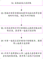
Fig. 1 is a flowchart of a method for correcting radiation of remote sensing satellite images according to an embodiment of the present disclosure. As shown, the method includes steps S1-S5 as follows.
In step S1, a remote sensing satellite image is acquired.
In this embodiment, the remote sensing satellite image may be an uncorrected 0-level image, and the remote sensing satellite image includes a non-vignetting image block and a vignetting image block.
In one example, the vignetting area and the non-vignetting area in the remote sensing satellite image can be divided into a plurality of image blocks according to the width of the vignetting area, so that the non-vignetting image blocks and the vignetting image blocks are obtained. Illustratively, the remote sensing satellite image map shown in fig. 2a has black bars as vignetting regions and other portions than the black bars as non-vignetting regions. Alternatively, the non-vignetting blocks and vignetting blocks may be 100 × 100 sized blocks. It will be appreciated that the remote sensing satellite imagery may include at least one non-vignetting image block and at least one vignetting image block.
In step S2, a ridge regression model is determined from the overall mean value of the non-vignetting blocks and the column mean value of the vignetting blocks.
In this embodiment, the integral mean value of all pixels in each non-vignetting block and the column mean value of each column of pixels in each vignetting block may be calculated first, and then the integral mean value and the column mean value may be subjected to ridge regression fitting to obtain parameters of a ridge regression model, thereby obtaining a ridge regression model between the non-vignetting blocks and the vignetting blocks. The column mean is the input quantity of the ridge regression function, and the overall mean is the output quantity of the ridge regression function. It will be appreciated that the column mean of each column in the vignetting block corresponds to a parameter of a ridge regression model.
In one example, when obtaining the ridge regression model, a first non-vignetting image block with uniform texture can be determined from the gray level co-occurrence matrix of the non-vignetting image blocks in the at least one non-vignetting image block, and the overall mean value of the first non-vignetting image block is used for ridge regression fitting. Specifically, after a gray level co-occurrence matrix of each non-vignetting image block is obtained, the inverse difference moment and the entropy value of each non-vignetting image block are calculated according to the gray level co-occurrence matrix, and then a first non-vignetting image block is screened out from at least one non-vignetting image block according to a preset inverse difference moment threshold value and an entropy threshold value. Alternatively, a non-vignetting image block with an inverse difference moment greater than an inverse difference moment threshold and an entropy less than an entropy threshold may be considered as a first non-vignetting image block with uniform texture.
In step S3, the pixel values of the vignetting block are corrected using the ridge regression model to obtain a first remote sensing satellite image.
In this embodiment, after obtaining the ridge regression model, the pixel values corresponding to the column mean values in the vignetting image block are input into the ridge regression model for vignetting correction, so as to obtain the corrected pixel values output by the ridge regression model. And then adjusting the pixel value corresponding to the mean value of the shading image block array to the pixel value output by the ridge regression model, thereby obtaining a corrected first image block corresponding to the shading image block. This process is repeated until all pixel values corresponding to the column mean in the vignetting block are vignetting corrected. It will be appreciated that the first remote sensing satellite image is obtained with vignetting correction, and therefore the first remote sensing satellite image comprises non-vignetting image blocks that have not been vignetting corrected and first image blocks obtained with vignetting correction. In an example, a row of pixel values corresponding to a row mean value in the vignetting image block may be all input into a ridge regression model for vignetting correction, and correspondingly, the ridge regression model also outputs a row of pixel values, and then the row of pixel values corresponding to the row mean value is adjusted to the ridge regression model also outputs a row of pixel values, so as to obtain a corrected first image block.
For example, when the pixel values of the vignetting image block of fig. 2a are substituted into the ridge regression model for vignetting correction, the corrected satellite image shown in fig. 2b can be obtained, and it can be seen that, in fig. 2b, after the correction by the ridge regression model, the vignetting problem therein is eliminated, and the image is more clearly recognizable.
In step S4, the first remote sensing satellite image is subjected to image registration to obtain a second remote sensing satellite image.
In this embodiment, a phase correlation method may be adopted to obtain a displacement difference of the first remote sensing satellite image, and the first remote sensing satellite image is subjected to sub-pixel level image registration based on the displacement difference to obtain a registered second remote sensing satellite image. Specifically, the first remote sensing satellite image may be subjected to image registration according to the obtained displacement difference, so as to obtain the second remote sensing satellite image. The image registration may also use a registration method conventional in the art, and is not limited to the registration method of the phase correlation method provided in this embodiment.
In step S5, an overlapping region in the second remote sensing satellite image is determined, and a pixel value of the overlapping region in the second remote sensing satellite image is corrected by using the adjustment model, so as to obtain a third remote sensing satellite image.
In this embodiment, parameters of the adjustment model may be initialized, then, pixel values of the overlapping region may be input into the adjustment model, parameters of the adjustment model may be iteratively updated by using a gradient descent method, and when the iteratively updated parameters of the adjustment model satisfy an iteration termination condition, a second pixel value of the overlapping region output by the adjustment optimization model may be obtained; and finally, adjusting the pixel value of the overlapping area to be a second pixel value, so that the chromatic aberration correction of the image in the overlapping area can be realized, and the second remote sensing satellite image is a third remote sensing satellite image after being corrected.
In one example, a pixel value sample may be screened from all pixel values in the overlap region according to a preset pixel value interval and the number of pixel values in each interval, and then the pixel value sample is used for training the adjustment model to determine parameters of the adjustment model. And then, performing adjustment optimization on all pixel values of the overlapping area by using an adjustment model, wherein the adjustment optimization process is described in the foregoing. Therefore, the time for determining the adjustment model can be saved, and the efficiency is improved. Alternatively, in order to ensure the accuracy of the adjustment model, the pixel value interval may be set to 30, and the pixel value of each interval may be set to 500.
For example, in the satellite images shown in fig. 3a, 3b, and 3c, as indicated by the marks in the figures, there is a significant color difference phenomenon in all three images, and therefore, after the adjustment model is determined by the pixel value samples, the adjustment model is used to perform color difference optimization on the images in the overlapping region in the satellite images shown in fig. 3a, 3b, and 3c, that is, the pixel values in the overlapping region in the three images are substituted into the adjustment model, and then the pixel values in the overlapping region are adjusted to the corresponding pixel values output by the adjustment model. Fig. 3a, 3b and 3c show three images of a satellite image obtained by color difference optimization, which are shown in fig. 4a, 4b and 4c, respectively, wherein fig. 4a is an image of the image of fig. 3a after color difference optimization, fig. 4b is an image of the image of fig. 3b after color difference optimization, and fig. 4c is an image of the image of fig. 3c after color difference optimization. Taking fig. 4a as an example, it is obvious from the figure that, at the same mark position as fig. 3a, the method of the present application can eliminate the color difference problem of the image
In an optional embodiment, before the image registration is performed on the first remote sensing satellite image, a pixel value of the first remote sensing satellite image, which is greater than a pixel threshold value, is adjusted to be a pixel threshold value, wherein the pixel threshold value may be set according to a maximum receiving brightness value of the CCD image sensor.
Fig. 5 is a schematic diagram of a device for correcting radiation of remote sensing satellite images according to an embodiment of the present disclosure. As shown in fig. 5, the device includes an acquisition module, a first correction module, a registration module, and a second correction module, wherein the acquisition module is configured to acquire a remote sensing satellite image; the remote sensing satellite image comprises a non-vignetting image block and a vignetting image block; the first correction module is used for determining a ridge regression model according to the overall mean value of the non-shading image blocks and the column mean value of the shading image blocks, and correcting the pixel values of the shading image blocks by using the ridge regression model to obtain a first remote sensing satellite image; the registration module is used for carrying out image registration on the first remote sensing satellite image to obtain a second remote sensing satellite image; and the second correction module is used for determining an overlapping area in the second remote sensing satellite image, correcting the pixel value of the overlapping area by using an adjustment model and obtaining a third remote sensing satellite image.
It is understood that the above-mentioned correction device is only an example of the embodiment of the present application, and is not limited to the specific division thereof, and therefore, in other embodiments, the correction device may include modules higher or lower than the above-mentioned five modules to implement the method steps described in the embodiment of the method of the present application.
In a possible implementation, the first correction module is specifically configured to: determining the non-vignetting image block as a first non-vignetting image block according to the gray level co-occurrence matrix of the non-vignetting image block; and carrying out ridge regression fitting on the whole average value of the first non-vignetting image block and the column average value of the vignetting image block to obtain the ridge regression model.
In a possible implementation, the first correction module is further configured to: determining an inverse difference moment and an entropy value of the non-vignetting image block according to the gray level co-occurrence matrix of the non-vignetting image block; and determining the non-vignetting image block as a first non-vignetting image block according to the inverse difference moment and the entropy value of the non-vignetting image block and the inverse difference moment threshold value and the entropy threshold value.
In a possible implementation, the first correction module is specifically configured to: inputting the pixel values corresponding to the column mean values in the shading image blocks into the ridge regression model to obtain the pixel values output by the ridge regression model; adjusting the pixel value corresponding to the row pixel mean value to the pixel value output by the ridge regression model to obtain a first image block; the first remote sensing satellite image comprises the non-shading image block and the first image block.
In a possible implementation, the registration module is further configured to: and adjusting the pixel value of the first remote sensing satellite image which is larger than the pixel threshold value to be the pixel threshold value before the image registration of the first remote sensing satellite image.
In a possible implementation, the second correction module is specifically configured to: inputting the pixel values of the overlapping area into a adjustment model, and iteratively updating parameters of the adjustment model by adopting a gradient descent method; when the parameters of the adjustment model meet the iteration termination condition, obtaining a second pixel value output by the adjustment optimization model; and adjusting the pixel value of the overlapping area to the second pixel value to obtain a third remote sensing satellite image.
Embodiments of the present application also provide a computing device that includes a memory and a processor. The memory stores computer instructions, and the processor, when reading the computer instructions, implements the method steps in the above method embodiments.
It is understood that the processor in the embodiments of the present application may be a Central Processing Unit (CPU), other general purpose processor, a Digital Signal Processor (DSP), an Application Specific Integrated Circuit (ASIC), a Field Programmable Gate Array (FPGA) or other programmable logic device, a transistor logic device, a hardware component, or any combination thereof. The general purpose processor may be a microprocessor, but may be any conventional processor.
The method steps in the embodiments of the present application may be implemented by hardware, or may be implemented by software instructions executed by a processor. The software instructions may consist of corresponding software modules that may be stored in Random Access Memory (RAM), flash memory, read-only memory (ROM), programmable read-only memory (PROM), Erasable Programmable ROM (EPROM), Electrically Erasable Programmable ROM (EEPROM), registers, a hard disk, a removable hard disk, a CD-ROM, or any other form of storage medium known in the art. An exemplary storage medium is coupled to the processor such the processor can read information from, and write information to, the storage medium. Of course, the storage medium may also be integral to the processor. The processor and the storage medium may reside in an ASIC.
In the above embodiments, the implementation may be wholly or partially realized by software, hardware, firmware, or any combination thereof. When implemented in software, may be implemented in whole or in part in the form of a computer program product. The computer program product includes one or more computer instructions. When loaded and executed on a computer, cause the processes or functions described in accordance with the embodiments of the application to occur, in whole or in part. The computer may be a general purpose computer, a special purpose computer, a network of computers, or other programmable device. The computer instructions may be stored in or transmitted over a computer-readable storage medium. The computer instructions may be transmitted from one website site, computer, server, or data center to another website site, computer, server, or data center via wired (e.g., coaxial cable, fiber optic, Digital Subscriber Line (DSL)) or wireless (e.g., infrared, wireless, microwave, etc.). The computer-readable storage medium can be any available medium that can be accessed by a computer or a data storage device, such as a server, a data center, etc., that incorporates one or more of the available media. The usable medium may be a magnetic medium (e.g., floppy disk, hard disk, magnetic tape), an optical medium (e.g., DVD), or a semiconductor medium (e.g., Solid State Disk (SSD)), among others.
It is to be understood that the various numerical references referred to in the embodiments of the present application are merely for descriptive convenience and are not intended to limit the scope of the embodiments of the present application.
Claims (12)
1. A radiation correction method for remote sensing satellite images is characterized by comprising the following steps:
acquiring a remote sensing satellite image; the remote sensing satellite image comprises a non-vignetting image block and a vignetting image block;
determining a ridge regression model according to the overall mean value of the non-shading image blocks and the column mean value of the shading image blocks;
correcting the pixel value of the shading image block by using the ridge regression model to obtain a first remote sensing satellite image;
carrying out image registration on the first remote sensing satellite image to obtain a second remote sensing satellite image;
and determining an overlapping area in the second remote sensing satellite image, and correcting the pixel value of the overlapping area by using an adjustment model to obtain a third remote sensing satellite image.
2. The method of claim 1, wherein determining a ridge regression model from the overall mean of the non-vignetting blocks and the column mean of the vignetting blocks comprises:
determining the non-vignetting image block as a first non-vignetting image block according to the gray level co-occurrence matrix of the non-vignetting image block;
and carrying out ridge regression fitting on the whole average value of the first non-vignetting image block and the column average value of the vignetting image block to obtain the ridge regression model.
3. The method of claim 2, wherein the determining the non-vignetting blocks as first non-vignetting blocks according to a gray co-occurrence matrix of the non-vignetting blocks comprises:
determining an inverse difference moment and an entropy value of the non-vignetting image block according to the gray level co-occurrence matrix of the non-vignetting image block;
and determining the non-vignetting image block as a first non-vignetting image block according to the inverse difference moment and the entropy value of the non-vignetting image block and the inverse difference moment threshold value and the entropy threshold value.
4. The method of claim 1, wherein the correcting the vignetting blocks using the ridge regression model to obtain a first remote sensing satellite image comprises:
inputting the pixel values corresponding to the column mean values in the shading image blocks into the ridge regression model to obtain the pixel values output by the ridge regression model;
adjusting the pixel value corresponding to the row pixel mean value to the pixel value output by the ridge regression model to obtain a first image block; the first remote sensing satellite image comprises the non-shading image block and the first image block.
5. The method of claim 1, further comprising:
and adjusting the pixel value of the first remote sensing satellite image which is larger than the pixel threshold value to be the pixel threshold value before the image registration of the first remote sensing satellite image.
6. The method of claim 1, wherein the correcting pixel values of the overlapping region in the second remote sensing satellite image using the adjustment model to obtain a third remote sensing satellite image comprises:
inputting the pixel values of the overlapping area into a adjustment model, and iteratively updating parameters of the adjustment model by adopting a gradient descent method;
when the parameters of the adjustment model meet the iteration termination condition, obtaining a second pixel value output by the adjustment optimization model;
and adjusting the pixel value of the overlapping area to the second pixel value to obtain a third remote sensing satellite image.
7. A device for radiometric correction of remotely sensed satellite images, said device comprising:
the acquisition module is used for acquiring remote sensing satellite images; the remote sensing satellite image comprises a non-vignetting image block and a vignetting image block;
the first correction module is used for determining a ridge regression model according to the whole average value of the non-shading image blocks and the column average value of the shading image blocks;
the first correction module is further used for correcting the pixel value of the shading image block by using the ridge regression model to obtain a first remote sensing satellite image;
the registration module is used for carrying out image registration on the first remote sensing satellite image to obtain a second remote sensing satellite image;
and the second correction module is used for determining an overlapping area in the second remote sensing satellite image, correcting the pixel value of the overlapping area by using an adjustment model and obtaining a third remote sensing satellite image.
8. The apparatus of claim 7, wherein the first correction module is specifically configured to:
determining the non-vignetting image block as a first non-vignetting image block according to the gray level co-occurrence matrix of the non-vignetting image block;
and carrying out ridge regression fitting on the whole average value of the first non-vignetting image block and the column average value of the vignetting image block to obtain the ridge regression model.
9. The apparatus of claim 8, wherein the first correction module is further configured to:
determining an inverse difference moment and an entropy value of the non-vignetting image block according to the gray level co-occurrence matrix of the non-vignetting image block;
and determining the non-vignetting image block as a first non-vignetting image block according to the inverse difference moment and the entropy value of the non-vignetting image block and the inverse difference moment threshold value and the entropy threshold value.
10. The apparatus of claim 7, wherein the first correction module is specifically configured to:
inputting the pixel values corresponding to the column mean values in the shading image blocks into the ridge regression model to obtain the pixel values output by the ridge regression model;
adjusting the pixel value corresponding to the row pixel mean value to the pixel value output by the ridge regression model to obtain a first image block; the first remote sensing satellite image comprises the non-shading image block and the first image block.
11. The apparatus of claim 7, wherein the registration module is further configured to:
and adjusting the pixel value of the first remote sensing satellite image which is larger than the pixel threshold value to be the pixel threshold value before the image registration of the first remote sensing satellite image.
12. The apparatus of claim 7, wherein the second correction module is specifically configured to:
inputting the pixel values of the overlapping area into a adjustment model, and iteratively updating parameters of the adjustment model by adopting a gradient descent method;
when the parameters of the adjustment model meet the iteration termination condition, obtaining a second pixel value output by the adjustment optimization model;
and adjusting the pixel value of the overlapping area to the second pixel value to obtain a third remote sensing satellite image.
Priority Applications (1)
| Application Number | Priority Date | Filing Date | Title |
|---|---|---|---|
| CN202110731534.1A CN113409366B (en) | 2021-06-29 | 2021-06-29 | Radiation correction method and device for remote sensing satellite image |
Applications Claiming Priority (1)
| Application Number | Priority Date | Filing Date | Title |
|---|---|---|---|
| CN202110731534.1A CN113409366B (en) | 2021-06-29 | 2021-06-29 | Radiation correction method and device for remote sensing satellite image |
Publications (2)
| Publication Number | Publication Date |
|---|---|
| CN113409366A true CN113409366A (en) | 2021-09-17 |
| CN113409366B CN113409366B (en) | 2022-11-22 |
Family
ID=77680214
Family Applications (1)
| Application Number | Title | Priority Date | Filing Date |
|---|---|---|---|
| CN202110731534.1A Active CN113409366B (en) | 2021-06-29 | 2021-06-29 | Radiation correction method and device for remote sensing satellite image |
Country Status (1)
| Country | Link |
|---|---|
| CN (1) | CN113409366B (en) |
Citations (6)
| Publication number | Priority date | Publication date | Assignee | Title |
|---|---|---|---|---|
| US20060204128A1 (en) * | 2005-03-07 | 2006-09-14 | Silverstein D A | System and method for correcting image vignetting |
| CN102937454A (en) * | 2012-11-13 | 2013-02-20 | 航天恒星科技有限公司 | Energy compensation and chromatic aberration removal method for total-reflection optical splicing cameras |
| CN108055487A (en) * | 2017-12-19 | 2018-05-18 | 清华大学 | The consistent bearing calibration of image sensor array inhomogeneities and system |
| US10325370B1 (en) * | 2016-05-31 | 2019-06-18 | University Of New Brunswick | Method and system of coregistration of remote sensing images |
| CN112233190A (en) * | 2020-05-19 | 2021-01-15 | 同济大学 | Satellite remote sensing image color balancing method based on block adjustment |
| CN112529807A (en) * | 2020-12-15 | 2021-03-19 | 北京道达天际科技有限公司 | Relative radiation correction method and device for satellite image |
-
2021
- 2021-06-29 CN CN202110731534.1A patent/CN113409366B/en active Active
Patent Citations (6)
| Publication number | Priority date | Publication date | Assignee | Title |
|---|---|---|---|---|
| US20060204128A1 (en) * | 2005-03-07 | 2006-09-14 | Silverstein D A | System and method for correcting image vignetting |
| CN102937454A (en) * | 2012-11-13 | 2013-02-20 | 航天恒星科技有限公司 | Energy compensation and chromatic aberration removal method for total-reflection optical splicing cameras |
| US10325370B1 (en) * | 2016-05-31 | 2019-06-18 | University Of New Brunswick | Method and system of coregistration of remote sensing images |
| CN108055487A (en) * | 2017-12-19 | 2018-05-18 | 清华大学 | The consistent bearing calibration of image sensor array inhomogeneities and system |
| CN112233190A (en) * | 2020-05-19 | 2021-01-15 | 同济大学 | Satellite remote sensing image color balancing method based on block adjustment |
| CN112529807A (en) * | 2020-12-15 | 2021-03-19 | 北京道达天际科技有限公司 | Relative radiation correction method and device for satellite image |
Non-Patent Citations (3)
| Title |
|---|
| 张兆明 等: "一种改进的遥感影像地形校正物理模型", 《光谱学与光谱分析》 * |
| 邵艳坡 等: "遥感影像相对辐射校正的PIF方法", 《国土资源遥感》 * |
| 黄莉婷 等: "基于正则化IR-MAD的GF-1影像辐射归一化", 《遥感信息》 * |
Also Published As
| Publication number | Publication date |
|---|---|
| CN113409366B (en) | 2022-11-22 |
Similar Documents
| Publication | Publication Date | Title |
|---|---|---|
| US7733391B2 (en) | Method and system for black-level correction on digital image data | |
| TWI328962B (en) | ||
| CN100585634C (en) | A kind of relative radiation correction method of star-load TDICCD camera | |
| CN112367474B (en) | Self-adaptive light field imaging method, device and equipment | |
| CN112529807B (en) | Relative radiation correction method and device for satellite image | |
| CN101510962B (en) | Method and apparatus for correcting lens shadow | |
| CN103226819A (en) | Segmental counting-based relative radiation correction method | |
| CN101889869B (en) | Imaging apparatus and control method thereof | |
| US7796153B1 (en) | Equalization system and method for an imaging sensor | |
| CN107093196A (en) | The in-orbit relative radiometric calibration method of video satellite area array cameras | |
| CN107818542A (en) | The restorative procedure and device of a kind of anamorphose | |
| CN105869129B (en) | For the thermal infrared images residue non-uniform noise minimizing technology after nonuniformity correction | |
| CN114862929A (en) | Three-dimensional target detection method and device, computer readable storage medium and robot | |
| US20050157942A1 (en) | System and method for estimating noise using measurement based parametric fitting non-uniformity correction | |
| CN111179184B (en) | Fish-eye image effective region extraction method based on random sampling consistency | |
| CN110542482B (en) | Blind pixel detection method and device and electronic equipment | |
| CN111063029A (en) | Map construction method and device, computer readable storage medium and robot | |
| CN113409366B (en) | Radiation correction method and device for remote sensing satellite image | |
| CN113379636A (en) | Infrared image non-uniformity correction method, device, equipment and storage medium | |
| CN114663530A (en) | Relative radiometric calibration method and device for remote sensing image yawing at 90 degrees | |
| CN113936221B (en) | Method and system applied to highway environment monitoring in plateau area | |
| CN116430069A (en) | Machine vision fluid flow velocity measuring method, device, computer equipment and storage medium | |
| US11900570B2 (en) | Image processing system for performing image quality tuning and method of performing image quality tuning | |
| CN114820376A (en) | Fusion correction method and device for stripe noise, electronic equipment and storage medium | |
| CN115209000A (en) | Dynamic phase difference estimation method and system for remote sensing imaging |
Legal Events
| Date | Code | Title | Description |
|---|---|---|---|
| PB01 | Publication | ||
| PB01 | Publication | ||
| SE01 | Entry into force of request for substantive examination | ||
| SE01 | Entry into force of request for substantive examination | ||
| GR01 | Patent grant | ||
| GR01 | Patent grant |